D7W TS.pdf - Espar
D7W TS.pdf - Espar
D7W TS.pdf - Espar

You also want an ePaper? Increase the reach of your titles
YUMPU automatically turns print PDFs into web optimized ePapers that Google loves.
29<br />
3. Fuel Quantity Test<br />
The fuel Quantity should be tested if the heater has<br />
difficulty starting or maintaining a flame.<br />
Note: Measure the fuel quantity when the battery<br />
is sufficiently charged. At least 11/22V and<br />
at most 13/26V should be applied at the<br />
control unit during measurement.<br />
A).<br />
Preparation<br />
- Detach the fuel line from the heater.<br />
- Insert the fuel line into a measuring glass.<br />
- Connect a voltmeter to terminals A13 (+) and A12<br />
(-) of the control unit.<br />
[C6 (+) and A4 (-) on models 25 1666/1667].<br />
- Disconnect the glow plug leads from the glow plug<br />
and connect a test light across the two leads.<br />
- Switch the heater on and allow the fuel line to<br />
bleed.(approx. 25-55 seconds)<br />
- Switch off the heater and empty the measuring<br />
glass.<br />
B). Measurement<br />
- Switch on the heater.<br />
- Hold the fuel line in the measuring glass while fuel<br />
is being delivered.<br />
- Fuel starts being pumped 25 - 55 seconds after<br />
switch-on.<br />
- Hold the measuring glass at the level of the plug<br />
during measurement.<br />
- Read the voltage at the voltmeter.<br />
- The pump will stop delivering fuel automatically<br />
after 90 seconds.<br />
- Switch off the heater.<br />
C. Evaluation<br />
- Read the fuel quantity in the measuring glass.<br />
- Transpose the readings into the appropriate<br />
diagram. Figures IV F<br />
- The fuel consumption is OK if the intersection of<br />
the two readings are within the limit curves.<br />
- If the intersection is outside the limit curves, inspect<br />
the fuel system and replace fuel metering pump if<br />
necessary.<br />
Note: Do not adjust fuel metering pump.<br />
Adjustments will only provide a tempora ry fix.<br />
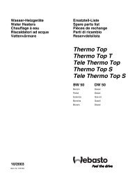
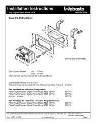
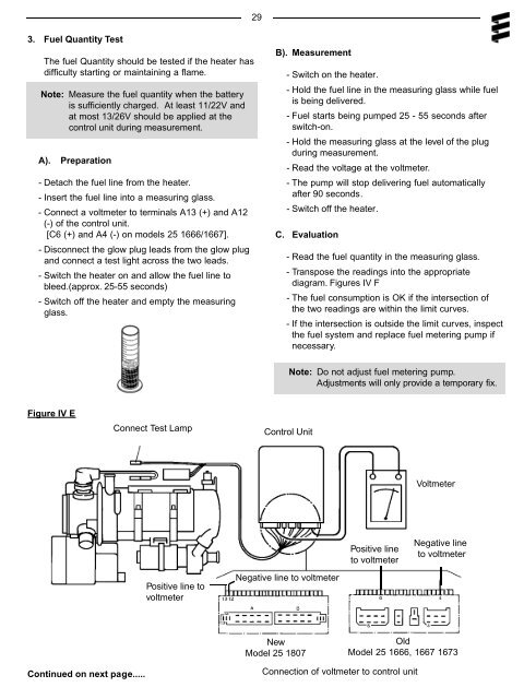
Figure IV E<br />
Connect Test Lamp<br />
Control Unit<br />
Voltmeter<br />
Positive line<br />
to voltmeter<br />
Negative line<br />
to voltmeter<br />
Positive line to<br />
voltmeter<br />
Negative line to voltmeter<br />
New<br />
Model 25 1807<br />
Old<br />
Model 25 1666, 1667 1673<br />
Continued on next page.....<br />
Connection of voltmeter to control unit