Wind Direction Sensor User Manual - MicroDAQ.com
Wind Direction Sensor User Manual - MicroDAQ.com
Wind Direction Sensor User Manual - MicroDAQ.com

Create successful ePaper yourself
Turn your PDF publications into a flip-book with our unique Google optimized e-Paper software.
<strong>Wind</strong> <strong>Direction</strong> Smart <strong>Sensor</strong><br />
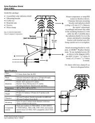
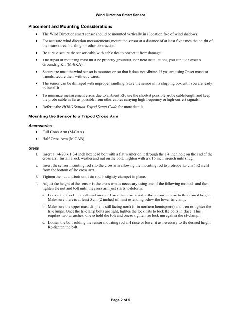
Placement and Mounting Considerations<br />
• The <strong>Wind</strong> <strong>Direction</strong> smart sensor should be mounted vertically in a location free of wind shadows.<br />
• For accurate wind direction measurements, mount the sensor at a distance of at least five times the height of<br />
the nearest tree, building, or other obstruction.<br />
• Be sure to secure the sensor cable with cable ties to protect it from damage.<br />
• The tripod or mounting mast must be properly grounded. For field installations, you can use Onset’s<br />
Grounding Kit (M-GKA).<br />
• Secure the mast the wind sensor is mounted on so that it does not vibrate. If you are using Onset masts or<br />
tripods, secure them with guy wires.<br />
• The sensor can be damaged with improper handling. Store the sensor in its shipping box until you are ready<br />
to install it.<br />
• To minimize measurement errors due to ambient RF, use the shortest possible probe cable length and keep<br />
the probe cable as far as possible from other cables carrying high frequency or high-current signals.<br />
• Refer to the HOBO Station Tripod Setup Guide for more details.<br />
Mounting the <strong>Sensor</strong> to a Tripod Cross Arm<br />
Accessories<br />
• Full Cross Arm (M-CAA)<br />
• Half Cross Arm (M-CAB)<br />
Steps<br />
1. Insert a 1/4-20 x 1 3/4 inch hex head bolt with a flat washer on it through the 1/4 inch hole on the end of the<br />
cross arm. Install a lock washer and nut on the bolt. Tighten with a 7/16 inch wrench until snug.<br />
2. Insert the sensor mounting rod into the cross arm allowing the mounting rod to protrude 1.3 cm (1/2 inch)<br />
from the bottom of the cross arm.<br />
3. Tighten the nut and bolt until the rod is slightly clamped in place.<br />
4. Adjust the height of the sensor in the cross arm as necessary using one of the following methods and then<br />
tighten the nut and bolt until the cross arm just starts to deform.<br />
a. Loosen the tri-clamp bolts and raise or lower the entire mast so the sensor is close to the desired height.<br />
Make sure there is at least 5 cm (2 inches) of mast extending below the lower tri-clamp.<br />
b. Make sure the upper mast dimple is still facing north (if in northern hemisphere) and then re-tighten the<br />
tri-clamps. Once the tri-clamp bolts are tight, tighten the lock nuts to lock the bolts in place. This<br />
requires two wrenches: one to hold the bolt and one to tighten the lock nut against the tri-clamp.<br />
c. Loosen the bolt holding the sensor mounting rod and raise or lower it as necessary to the desired height.<br />
Re-tighten the bolt.<br />
Page 2 of 5