Wind Direction Sensor User Manual - MicroDAQ.com
Wind Direction Sensor User Manual - MicroDAQ.com
Wind Direction Sensor User Manual - MicroDAQ.com

You also want an ePaper? Increase the reach of your titles
YUMPU automatically turns print PDFs into web optimized ePapers that Google loves.
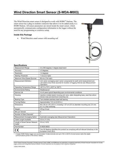
<strong>Wind</strong> <strong>Direction</strong> Smart <strong>Sensor</strong> (S-WDA-M003)<br />
The <strong>Wind</strong> <strong>Direction</strong> smart sensor is designed to work with HOBO ® Stations. The<br />
smart sensor has a plug-in modular connector that allows it to be added easily to a<br />
HOBO Station. All sensor parameters are stored inside the smart sensor, which<br />
automatically <strong>com</strong>municates configuration information to the logger without the<br />
need for any programming or extensive setup.<br />
Inside this Package<br />
• <strong>Wind</strong> <strong>Direction</strong> smart sensor with mounting rod<br />
Specifications<br />
Measurement Range<br />
Accuracy<br />
Resolution<br />
Starting Threshold<br />
Maximum <strong>Wind</strong> Speed Survival<br />
Measurement Definition<br />
Operating Temperature Range<br />
Environmental Rating<br />
Service Life<br />
0 to 355 degrees, 5 degree dead band<br />
± 5 degrees<br />
1.4 degrees<br />
1 m/s (2.2 mph)<br />
60 m/s (134 mph)<br />
Unit vector averaging used; vector <strong>com</strong>ponents for each wind measurement are<br />
calculated every three seconds for duration of logging interval (see Measurement<br />
Operation)<br />
-40°C to 70°C (-40°F to 158°F)<br />
Weatherproof<br />
4 to 6 years typical depending upon environmental conditions<br />
Housing<br />
Injection-molded plastic housing and vane, static dissipating base, lead-free silicon<br />
bronze nose and aluminum mounting rod<br />
Bearing Type<br />
Two shielded stainless steel ball bearing<br />
Turning Radius<br />
Approximately 13.5 cm (5.25 in.)<br />
Dimensions<br />
46 x 20 cm (18 x 8.5 in.) including 1.27 cm (0.5 in) diameter mounting rod; 2.5 mm<br />
(0.1 in.) drip overhang<br />
Weight<br />
370 g (13 oz)<br />
Bits per Sample 8<br />
Number of Data Channels* 1<br />
Measurement Averaging Option<br />
Cable Length Available<br />
Length of Smart <strong>Sensor</strong> Network<br />
Cable*<br />
Part Number<br />
Automatic averaging (see Measurement Operation)<br />
3.5 m (11.5 ft)<br />
0.5 m (1.6 ft)<br />
S-WDA-M003<br />
The CE Marking identifies this product as <strong>com</strong>plying with all relevant directives in the<br />
European Union (EU).<br />
* A single HOBO Station logger can ac<strong>com</strong>modate 15 data channels and up to 100 m (325 ft) of smart sensor cable (the digital<br />
<strong>com</strong>munications portion of the sensor cables).<br />
© 2011 Onset Computer Corporation. All rights reserved. Onset, HOBO, and HOBOware are trademarks or registered trademarks of Onset Computer Corporation for its data<br />
logger products and configuration/interface software. All other trademarks are the property of their respective <strong>com</strong>panies.<br />
15290-A MAN-SWDA
<strong>Wind</strong> <strong>Direction</strong> Smart <strong>Sensor</strong><br />
Placement and Mounting Considerations<br />
• The <strong>Wind</strong> <strong>Direction</strong> smart sensor should be mounted vertically in a location free of wind shadows.<br />
• For accurate wind direction measurements, mount the sensor at a distance of at least five times the height of<br />
the nearest tree, building, or other obstruction.<br />
• Be sure to secure the sensor cable with cable ties to protect it from damage.<br />
• The tripod or mounting mast must be properly grounded. For field installations, you can use Onset’s<br />
Grounding Kit (M-GKA).<br />
• Secure the mast the wind sensor is mounted on so that it does not vibrate. If you are using Onset masts or<br />
tripods, secure them with guy wires.<br />
• The sensor can be damaged with improper handling. Store the sensor in its shipping box until you are ready<br />
to install it.<br />
• To minimize measurement errors due to ambient RF, use the shortest possible probe cable length and keep<br />
the probe cable as far as possible from other cables carrying high frequency or high-current signals.<br />
• Refer to the HOBO Station Tripod Setup Guide for more details.<br />
Mounting the <strong>Sensor</strong> to a Tripod Cross Arm<br />
Accessories<br />
• Full Cross Arm (M-CAA)<br />
• Half Cross Arm (M-CAB)<br />
Steps<br />
1. Insert a 1/4-20 x 1 3/4 inch hex head bolt with a flat washer on it through the 1/4 inch hole on the end of the<br />
cross arm. Install a lock washer and nut on the bolt. Tighten with a 7/16 inch wrench until snug.<br />
2. Insert the sensor mounting rod into the cross arm allowing the mounting rod to protrude 1.3 cm (1/2 inch)<br />
from the bottom of the cross arm.<br />
3. Tighten the nut and bolt until the rod is slightly clamped in place.<br />
4. Adjust the height of the sensor in the cross arm as necessary using one of the following methods and then<br />
tighten the nut and bolt until the cross arm just starts to deform.<br />
a. Loosen the tri-clamp bolts and raise or lower the entire mast so the sensor is close to the desired height.<br />
Make sure there is at least 5 cm (2 inches) of mast extending below the lower tri-clamp.<br />
b. Make sure the upper mast dimple is still facing north (if in northern hemisphere) and then re-tighten the<br />
tri-clamps. Once the tri-clamp bolts are tight, tighten the lock nuts to lock the bolts in place. This<br />
requires two wrenches: one to hold the bolt and one to tighten the lock nut against the tri-clamp.<br />
c. Loosen the bolt holding the sensor mounting rod and raise or lower it as necessary to the desired height.<br />
Re-tighten the bolt.<br />
Page 2 of 5
<strong>Wind</strong> <strong>Direction</strong> Smart <strong>Sensor</strong><br />
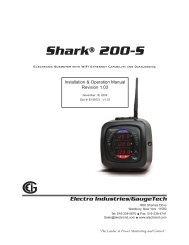
5. Use cable ties to secure the sensor cables to the cross arm, bracket, and mast. The sensor cables should run<br />
below the cross arm and brackets to minimize the chance of birds pecking and damaging the cables. Cable<br />
ties should be spaced no more than 0.3 m (1 foot) apart.<br />
Cable ties<br />
Mounting rod<br />
Upper mast<br />
<strong>Sensor</strong> cable<br />
6. Follow the steps in the North Alignment section.<br />
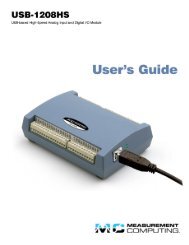
Mounting the <strong>Sensor</strong> to a Pole<br />
1. Loosely secure the sensor with two hose clamps (not included). Adjust the height as necessary, but make<br />
sure the hose clamps are separated by at least 4 inches (10 cm).<br />
2. Secure the sensor cable with cable ties.<br />
Hose clamps<br />
Mounting rod<br />
Cable ties around<br />
sensor cable<br />
3. Tighten the hose clamps making sure the mounting rod remains vertical.<br />
4. Follow the steps in the North Alignment section.<br />
Page 3 of 5
<strong>Wind</strong> <strong>Direction</strong> Smart <strong>Sensor</strong><br />
North Alignment<br />
The wind direction sensor must be oriented properly to obtain meaningful data. This involves aligning the north<br />
markings on the base of the sensor with true north. There are two methods to align the sensor:<br />
• Compass Alignment<br />
• Global Positioning Satellite (GPS) alignment.<br />
Note: The magnetic declination must be known to align the direction sensor to true north using a magnetic <strong>com</strong>pass.<br />
Worldwide declination information is available from the National Space Science Data Center at:<br />
http://nssdc.gsfc.nasa.gov/space/cgm/cgm.html.<br />
Compass Alignment<br />
Tools required:<br />
• Compass<br />
• Binoculars<br />
• Tape (such as electrical, packing, or duct tape)<br />
Two people are required to <strong>com</strong>plete this procedure.<br />
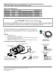
1. Align bronze tip of the wind vane with the north markings on the base.<br />
North markings<br />
2. Secure the base and vane shaft with a piece of tape so that the vane cannot rotate.<br />
3. While standing 150 to 200 feet south of the sensor, use the <strong>com</strong>pass to determine magnetic north. If true<br />
north is the same as magnetic north, align yourself so the <strong>com</strong>pass points north and directly at the sensor. If<br />
you are in area with an east variation, align yourself so that the station is that number of degrees to the east<br />
of magnetic north. If you are in an area with a west variation, align yourself so that the station is that<br />
number of degrees to the west of magnetic north.<br />
4. While viewing the sensor through binoculars, instruct another person to rotate the sensor mounting rod to<br />
point the vane north. The vane should seem to disappear from sight when properly aligned.<br />
5. Once you’ve obtained the correct position, secure the mounting rod and remove the tape.<br />
GPS Alignment<br />
Tools required:<br />
• Handheld GPS with WAAS-enabled receiver or any similar high accuracy GPS device<br />
• Flag, orange cone, or other temporary marker<br />
• Laptop <strong>com</strong>puter with logger software installed<br />
Page 4 of 5
<strong>Wind</strong> <strong>Direction</strong> Smart <strong>Sensor</strong><br />
This procedure requires only one person, but is easier to <strong>com</strong>plete with two people. In this procedure, you will be<br />
using the GPS receiver first to create an arbitrary waypoint and then to determine the bearing from the sensor to that<br />
waypoint. You will then align the sensor so that when the vane is pointed at the waypoint, the direction reported by<br />
the logger software matches the GPS receiver’s bearing to the waypoint.<br />
1. Connect the sensor to the logger (refer to the Connecting to the Logger section below).<br />
2. Connect the laptop to the logger with the PC interface cable.<br />
3. Pick a visible location that is at least 100 meters (110 yards) away from the wind direction sensor and walk<br />
to it. Establish a waypoint with the handheld GPS receiver. You may want to use averaging to minimize the<br />
waypoint position error if your GPS receiver is so equipped. (For best results, the estimated position error<br />
of the waypoint should be less than 10 feet if the distance to the sensor is 100 meters, and less than 20 feet<br />
for a distance of 200 meters.) Mark the waypoint with a flag, orange cone, or other suitable marker.<br />
4. Walk back to the sensor and determine the bearing to the waypoint you just created with the GPS receiver.<br />
Again you may need to determine the average value of the bearing to keep the errors to a minimum.<br />
5. Start the logger software and select Status to get the current reading (refer to the software manual or online<br />
help for details about operating the software).<br />
6. Point the sensor vane directly at the waypoint flag or marker and rotate the sensor mounting rod until the<br />
wind direction sensor value in the logger software matches the angle obtained with the GPS receiver.<br />
7. Once the vane is in position, secure the mounting rod and then double-check that the reported angle is<br />
correct.<br />
Connecting to the Logger<br />
To start using the <strong>Wind</strong> <strong>Direction</strong> sensor, stop the logger and insert the modular jack into an available port. If a port<br />
is not available, use a 1-to-2 adapter (S-ADAPT), which allows you to plug in two sensors into one port. The next<br />
time the logger is launched, it will automatically detect the new smart sensor. Note that the HOBO Station supports<br />
a maximum of 15 data channels. This sensor requires one channel. Launch the logger and verify the sensor is<br />
functioning correctly.<br />
Measurement Operation<br />
<strong>Wind</strong> direction measurements are averaged over the logging interval or a 3-second timeframe (whichever is greater).<br />
If you set up the sensor to log faster than every 3 seconds, the same sensor reading will be recorded until a new 3-<br />
second average is calculated. For example, if the sensor is logging at a 1-second interval, the sensor will report the<br />
same wind direction (its calculated average) for three samples before calculating and reporting a new value for<br />
another three samples.<br />
<strong>Direction</strong> Averaging<br />
Unit vector averaging is used to determine wind direction because traditional averaging would produce inaccurate<br />
results. For example, three measurements of 350, 11, and 12 degrees—which are all winds from the north—<br />
averaged together would result in 126 degrees, which incorrectly indicates a southeasterly wind. Instead, the vector<br />
<strong>com</strong>ponents (North/South and East/West) for each wind measurement are calculated every three seconds for the<br />
duration of the logging interval. At the conclusion of the logging interval, the North/South and East/West<br />
<strong>com</strong>ponents are averaged and then re-<strong>com</strong>bined to calculate the average wind direction for the logging interval.<br />
Maintenance<br />
The sensor does not normally require any maintenance other than an occasional cleaning. If the vane be<strong>com</strong>es dirty,<br />
rinse the sensor with mild soap and fresh water. Do not immerse the sensor in water or use any organic solvents to<br />
clean the unit.<br />
Verifying <strong>Sensor</strong> Accuracy<br />
It is re<strong>com</strong>mended that you check the accuracy of the sensor annually. The <strong>Wind</strong> <strong>Direction</strong> sensor cannot be<br />
calibrated. Onset uses precision <strong>com</strong>ponents to obtain accurate measurements. If the smart sensor is not providing<br />
accurate data, then it is damaged or possibly worn out if it has been in use for several years. If you are unsure of the<br />
accuracy, you can send the smart sensor back to Onset for inspection and possible replacement of the mechanism or<br />
bearings if required. Contact Onset or your dealer for a Return Merchandise Authorization (RMA) number before<br />
sending the sensor.<br />
Page 5 of 5