NETWORK TECHNOLOGY - SWS a.s.
NETWORK TECHNOLOGY - SWS a.s.
NETWORK TECHNOLOGY - SWS a.s.

You also want an ePaper? Increase the reach of your titles
YUMPU automatically turns print PDFs into web optimized ePapers that Google loves.
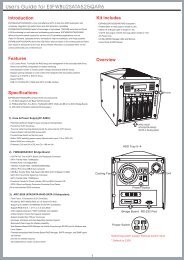
Cabling Standards<br />
DIN EN 50173-3<br />
Industrial area<br />
DIN EN 50173-1<br />
Office area<br />
DIN EN 50173-2<br />
SoHo<br />
DIN EN 50288<br />
Symmetrische Symmetrical cable Kabel<br />
DIN EN 60603- 7<br />
Connectors<br />
DIN EN 50310<br />
Potenzial Equalization<br />
and Grounding<br />
DIN EN 50174<br />
Construction and Operation<br />
DIN EN 50288-2- 1<br />
(shielded up to 100MHz)<br />
DIN EN 60603-7- 3<br />
(shielded up to 100MHz)<br />
DIN EN 50288-5- 1<br />
(shielded up to 250MHz)<br />
DIN EN 50288-4- 1<br />
(shielded up to 600MHz)<br />
DIN EN 60603-7- 5<br />
(shielded up to 250MHz)<br />
DIN EN 60603-7- 7<br />
(shielded up to 600MHz)<br />
Part 1<br />
Specification and<br />
Quality Control<br />
Part 2<br />
Installation Design and<br />
Practices in Buildings<br />
Part 3<br />
Installation Design and<br />
Practices in Outdoor<br />
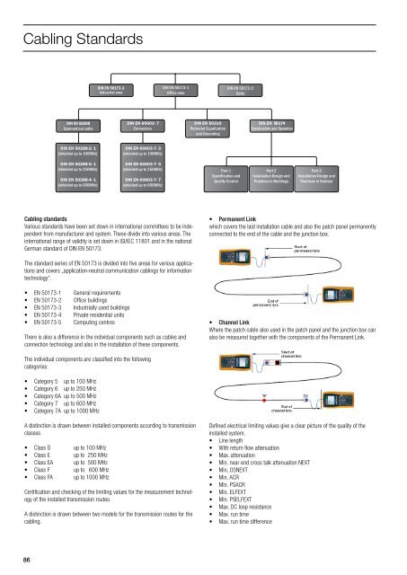
Cabling standards<br />
Various standards have been set down in international committees to be independent<br />
from manufacturer and system. These divide into various areas. The<br />
international range of validity is set down in ISI/IEC 11801 and in the national<br />
German standard of DIN EN 50173.<br />
• Permanent Link<br />
which covers the laid installation cable and also the patch panel permanently<br />
connected to the end of the cable and the junction box.<br />
The standard series of EN 50173 is divided into five areas for various applications<br />
and covers „application-neutral communication cablings for information<br />
technology”.<br />
• EN 50173-1 General requirements<br />
• EN 50173-2 Office buildings<br />
• EN 50173-3 Industrially used buildings<br />
• EN 50173-4 Private residential units<br />
• EN 50173-5 Computing centres<br />
There is also a difference in the individual components such as cables and<br />
connection technology and also in the installation of these components.<br />
• Channel Link<br />
Where the patch cable also used in the patch panel and the junction box can<br />
also be measured together with the components of the Permanent Link.<br />
The individual components are classified into the following<br />
categories:<br />
• Category 5 up to 100 MHz<br />
• Category 6 up to 250 MHz<br />
• Category 6A up to 500 MHz<br />
• Category 7 up to 600 MHz<br />
• Category 7A up to 1000 MHz<br />
A distinction is drawn between installed components according to transmission<br />
classes<br />
• Class D up to 100 MHz<br />
• Class E up to 250 MHz<br />
• Class EA up to 500 MHz<br />
• Class F up to 600 MHz<br />
• Class FA up to 1000 MHz<br />
Certification and checking of the limiting values for the measurement technology<br />
of the installed transmission routes.<br />
A distinction is drawn between two models for the transmission routes for the<br />
cabling.<br />
Defined electrical limiting values give a clear picture of the quality of the<br />
installed system.<br />
• Line length<br />
• With return flow attenuation<br />
• Max. attenuation<br />
• Min. near end cross talk attenuation NEXT<br />
• Min, OSNEXT<br />
• Min. ACR<br />
• Min. PSACR<br />
• Min. ELFEXT<br />
• Min. PSELFEXT<br />
• Max. DC loop resistance<br />
• Max. run time<br />
• Max. run time difference<br />
86