NETWORK TECHNOLOGY - SWS a.s.
NETWORK TECHNOLOGY - SWS a.s.
NETWORK TECHNOLOGY - SWS a.s.

You also want an ePaper? Increase the reach of your titles
YUMPU automatically turns print PDFs into web optimized ePapers that Google loves.
Structure of the Cabling System<br />
The return flow attenuation is the measure for outstanding<br />
reflection of the transmission signal which is created by sud<br />
den increases in impedance in the cable run (Return Loss).<br />
The attenuation shows the lost part of the signal over the<br />
cable run (Attenuation).<br />
The near end cross talk attenuation is used as a measure of<br />
cross talk at the near end of the cable run. Each pair of<br />
strands will be measured at the other pairs respectively<br />
(Near end crosstalk NEXT).<br />
The far end cross talk attenuation is measured as the same<br />
way as NEXT (Far end crosstalk FEXT).<br />
ACR measures the ratio between cross talk and attenuation.<br />
(Attenuation to crosstalk ratio ACR=NEXT - attenuation).<br />
Equal Level FEXT is the extent of crosstalk at the far end where<br />
the pair attenuation is deducted from this (ELFEXT).<br />
Run time of the signal over the transmission distance<br />
(Propagation delay).<br />
Run time differences arise with simultaneous transmission of<br />
a signal to various pairs (delay skew).<br />
Power Sum is the total of the faults which are coupled in from<br />
the remaining pairs to the fourth pair (PS).<br />
PSNEXT = Power Sum NEXT<br />
PSACR = Power Sum ACR<br />
PSELFEXT = Power Sum ELFEXT<br />
Structure of the cabling system in accordance with EN 50173<br />
Cabling takes place on different levels, not only storeys/floors<br />
are cabled but also different floors are cabled with each other<br />
and buildings are also cabled over outside surfaces.<br />
There different areas are defined for these applications.<br />
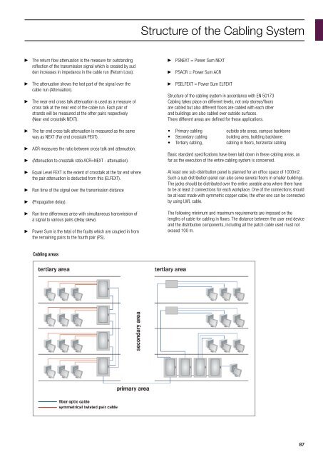
• Primary cabling outside site areas, campus backbone<br />
• Secondary cabling building area, building backbone<br />
• Tertiary cabling, cabling in floors, horizontal cabling<br />
Basic standard specifications have been laid down in these cabling areas, as<br />
far as the execution of the entire cabling system is concerned.<br />
At least one sub-distribution panel is planned for an office space of 1000m2.<br />
Such a sub distribution panel can also serve several floors in smaller buildings.<br />
The jacks should be distributed over the entire useable area where there have<br />
to be at least 2 connections for each workplace. One of the connections should<br />
be at least made with symmetric copper cable, the other one can be connected<br />
by using LWL cable.<br />
The following minimum and maximum requirements are imposed on the<br />
lengths of cable for cabling in floors. The distance between the user end device<br />
and the distribution components, including all the patch cable used must not<br />
exceed 100 m.<br />
Cabling areas<br />
87