F35-XXL Hardware description - Falcom
F35-XXL Hardware description - Falcom
F35-XXL Hardware description - Falcom

Create successful ePaper yourself
Turn your PDF publications into a flip-book with our unique Google optimized e-Paper software.
<strong>F35</strong>-<strong>XXL</strong> HARDWARE DESCRIPTION VERSION 1.10<br />
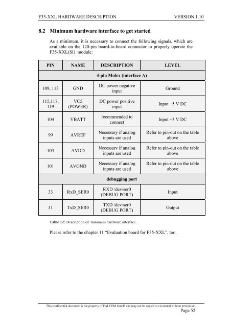
8.2 Minimum hardware interface to get started<br />
As a minimum, it is necessary to connect the following signals, which are<br />
available on the 120-pin board-to-board connector to properly operate the<br />
<strong>F35</strong>-<strong>XXL</strong>(SI) module:<br />
PIN NAME DESCRIPTION LEVEL<br />
109, 113 GND<br />
115,117,<br />
119<br />
VC5<br />
(POWER)<br />
104 VBATT<br />
99 AVREF<br />
103 AVDD<br />
101 AVGND<br />
33 RxD_SER0<br />
31 TxD_SER0<br />
4-pin Molex (interface A)<br />
DC power negative<br />
input<br />
DC power positive<br />
input<br />
recommended to<br />
connect<br />
Necessary if analog<br />
inputs are used<br />
Necessary if analog<br />
inputs are used<br />
Necessary if analog<br />
inputs are used<br />
debugging port<br />
RXD /dev/ser0<br />
(DEBUG PORT)<br />
TXD /dev/ser0<br />
(DEBUG PORT)<br />
Table 12: Description of minimum hardware interface.<br />
Ground<br />
Input +5 V DC<br />
Input +3 V DC<br />
Refer to pin-out on the table<br />
above<br />
Refer to pin-out on the table<br />
above<br />
Refer to pin-out on the table<br />
above<br />
Input<br />
Output<br />
Please refer to the chapter 11 “Evaluation board for <strong>F35</strong>-<strong>XXL</strong>”, too.<br />
This confidential document is the property of FALCOM GmbH and may not be copied or circulated without permission.<br />
Page 52