F35-XXL Hardware description - Falcom
F35-XXL Hardware description - Falcom
F35-XXL Hardware description - Falcom

You also want an ePaper? Increase the reach of your titles
YUMPU automatically turns print PDFs into web optimized ePapers that Google loves.
<strong>F35</strong>-<strong>XXL</strong> HARDWARE DESCRIPTION VERSION 1.10<br />
Designation<br />
JTAG<br />
AD0-7<br />
EMODE switch:<br />
IGNIT switch:<br />
USA switch:<br />
Position 0 ► The V850 boots the RedBoot from the<br />
internal ROM<br />
Position 1 ► The V850 boots the RedBoot from the<br />
external FLASH<br />
Position 0 ► The IGNITION line is set to high<br />
Position 1 ► The IGNITION line is set to low<br />
Position 0 ► The PWR_GOOD line is set to high<br />
Position 1 ► The PWR_GOOD line is set to low<br />
WakeUp button Pulls the WakeUp signal to low<br />
NMI button Polls the NMI signal to low<br />
RESET <strong>Hardware</strong> reset<br />
table14: <strong>F35</strong>-<strong>XXL</strong>- EVAL- BOARD -Button specification.<br />
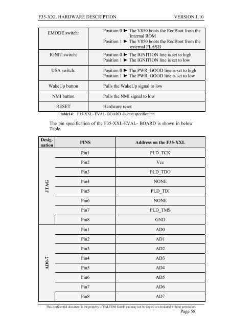
The pin specification of the <strong>F35</strong>-<strong>XXL</strong>-EVAL- BOARD is shown in below<br />
Table.<br />
PINS Address on the <strong>F35</strong>-<strong>XXL</strong><br />
Pin1 PLD_TCK<br />
Pin2 Vcc<br />
Pin3 PLD_TDO<br />
Pin4 NONE<br />
Pin5 PLD_TDI<br />
Pin6 NONE<br />
Pin7 PLD_TMS<br />
Pin8 GND<br />
Pin1 AD0<br />
Pin2 AD1<br />
Pin3 AD2<br />
Pin4 AD3<br />
Pin5 AD4<br />
Pin6 AD5<br />
Pin7 AD6<br />
Pin8 AD7<br />
This confidential document is the property of FALCOM GmbH and may not be copied or circulated without permission.<br />
Page 58