
Create successful ePaper yourself
Turn your PDF publications into a flip-book with our unique Google optimized e-Paper software.
User <strong>Manual</strong> <strong>LM5109</strong><br />
3. CONNECTIONS<br />
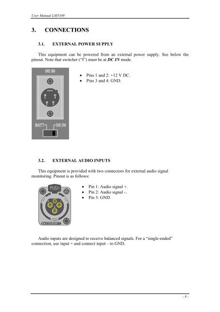
3.1. EXTERNAL POWER SUPPLY<br />
This equipment can be powered from an external power supply. See below the<br />
pinout. Note that switcher (“I”) must be at DC IN mode.<br />
• Pins 1 and 2: +12 V DC.<br />
• Pins 3 and 4: GND.<br />
3.2. EXTERNAL AUDIO INPUTS<br />
This equipment is provided with two connectors for external audio signal<br />
monitoring. Pinout is as follows:<br />
• Pin 1: Audio signal +.<br />
• Pin 2: Audio signal -.<br />
• Pin 3: GND.<br />
Audio inputs are designed to receive balanced signals. For a “single-ended”<br />
connection, use input + and connect input – to GND.<br />
- 8 -