SERVICE MANUAL FOR M35&36; CHASSIS
SERVICE MANUAL FOR M35&36; CHASSIS
SERVICE MANUAL FOR M35&36; CHASSIS

Create successful ePaper yourself
Turn your PDF publications into a flip-book with our unique Google optimized e-Paper software.
TCL<br />
Chassis M35&<strong>36</strong> Service Manual<br />
1.2.5. Manual Mode<br />
Below Fig. shows the source channel assignment of demodulated signals in case of manual mode.<br />
1.3. Preprocessing for SCART and I 2 S Input Signals<br />
The SCART and I 2 S inputs need only be adjusted in level by means of the SCART and I 2 S prescale registers.<br />
1.4. Source Selection and Output Channel Matrix<br />
The Source Selector makes it possible to distribute all source signals (one of the demodulator source channels<br />
or SCART) to the desired output channels (loudspeaker, etc.). All input and output signals can be processed<br />
simultaneously. Each source channel is identified by a unique source address.<br />
For each output channel, the sound mode can be set to sound A, sound B, stereo, or mono by means of the<br />
output channel matrix. If Automatic Sound Select is on, the output channel matrix can stay fixed to stereo<br />
(transparent) for demodulated signals.<br />
1.5. Audio Baseband Processing<br />
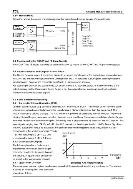
1.5.1. Automatic Volume Correction (AVC)<br />
Different sound sources (e.g. terrestrial channels, SAT channels, or SCART) fairly often do not have the same<br />
volume level. Advertisements during movies usually have a higher volume level than the movie itself. This<br />
results in annoying volume changes. The AVC solves this problem by equalizing the volume level. To prevent<br />
clipping, the AVC’s gain decreases quickly in dynamic boost conditions. To suppress oscillation effects, the gain<br />
increases rather slowly for low level inputs. The decay time is programmable by means of the AVC register . For<br />
input signals ranging from .24 dBr to 0 dBr, the AVC maintains a fixed output level of .18 dBr. Below Fig. shows<br />
the AVC output level versus its input level. For prescale and volume registers set to 0 dB, a level of 0 dBr<br />
corresponds to full scale input/output. This is<br />
– SCART input/output 0 dBr = 2.0 Vrms<br />
– Loudspeaker output 0 dBr = 1.4 Vrms<br />
1.5.2. Loudspeaker Outputs<br />
The following baseband features are<br />
implemented in the loudspeaker output<br />
channels: bass/treble, loudness, balance,<br />
and volume. A square wave beeper can<br />
be added to the loudspeaker channel.<br />
1.5.3. Quasi-Peak Detector<br />
Simplified AVC characteristics<br />
The quasi-peak readout register can be used to readout the quasi-peak level of any input source. The feature<br />
is based on following filter time constants:<br />
attack time: 1.3 ms<br />
30 03.Mar.2003