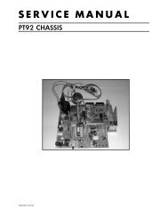
SERVICE MANUAL FOR M35&36; CHASSIS
SERVICE MANUAL FOR M35&36; CHASSIS
SERVICE MANUAL FOR M35&36; CHASSIS

Create successful ePaper yourself
Turn your PDF publications into a flip-book with our unique Google optimized e-Paper software.
TCL<br />
Chassis M35&<strong>36</strong> Service Manual<br />
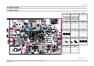
OPERATING DESCRIPTION<br />
Regulation<br />
The pin 3 senses the feedback current provided by the opto-coupler. During the switching phase the switch<br />
S2 is closed and the shunt regulator is accessible by the pin 3. The shunt regulator voltage is typically 5V.<br />
The dynamic resistance of the shunt regulator represented by the zener diode is 20 .<br />
The gain of the Control input is given on Figure 10 which shows the duty cycle as a function of the current<br />
injected into the pin 3.<br />
The maximum current sense threshold is fixed at 1V. The peak A 4KHz filter network is inserted<br />
between the shunt regulator and the<br />
PWM comparator to cancel the high<br />
frequency residual noise.<br />
The switch S3 is closed in Stand–by<br />
mode during the Latched Off Phase<br />
while the switch S2 remains open. (See<br />
section PULSED MODE DUTY<br />
CYCLE CONTROL).<br />
The resistor Rdpulsed (Rduty cycle<br />
burst) has no effect on the regulation<br />
process. This resistor is used to<br />
determine the burst duty cycle.<br />
PWM Latch<br />
The MC44608 works in voltage mode. The on–time is controlled by the PWM comparator that compares<br />
the oscillator sawtooth with the regulation block output.<br />
The PWM latch is initialized by the<br />
oscillator and is reset by the PWM<br />
comparator or by the current sense<br />
comparator in case of an over current.<br />
This configuration ensures that only a<br />
single pulse appears at the circuit<br />
output during an oscillator cycle.<br />
Current Sense<br />
The inductor current is converted to a<br />
positive voltage by inserting a ground<br />
reference sense resistor RSense in series<br />
with the power switch.<br />
The maximum current sense threshold is fixed at 1V. The peak current is given by the following equation:<br />
Ipkmax = 1/Rsense( ) (A)<br />
In stand–by mode, this current can be lowered as due to the activation of a 200 A current source:<br />
IpkMAX-STBY<br />
The current sense input consists of a filter (6k , 4pF) and of a leading edge blanking. Thanks to that, this<br />
pin is not sensitive to the power switch turn on noise and spikes and practically in most applications, no<br />
filtering network is required to sense the current.<br />
Finally, this pin is used:<br />
8 03.Mar.2003