SERVICE MANUAL FOR M35&36; CHASSIS
SERVICE MANUAL FOR M35&36; CHASSIS
SERVICE MANUAL FOR M35&36; CHASSIS

You also want an ePaper? Increase the reach of your titles
YUMPU automatically turns print PDFs into web optimized ePapers that Google loves.
TCL<br />
Chassis M35&<strong>36</strong> Service Manual<br />
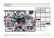
6. Vertical output section<br />
IC VCT3831A outputs vertical saw-tooth waveform from Pin33. It comes to pin1 of TDA8172 with DC<br />
coupling. And it is amplified by inner difference amplifier. Pin7 of TDA8172 is the same phase input<br />
terminal. R302 is DC offset resistances. In application to M35, pin7 of TDA8172 is connected with Pin34<br />
vert0. The amplified saw tooth-wave comes out from pin5 and make the deflect coil to generate the deflect<br />
current. R307 and C305 filtrate the inductive interference from the horizontal deflect coil. C307 is used to<br />
eliminate spurious oscillation generated by the deflect coil and distributed capacitance resonance. R312,<br />
R320 and accessory circuit are in charge of draw AC saw tooth wave out, and feedback to the input<br />
terminal of TDA8172 (pin1) to correct the linearity of horizontal scan. D302 and C301 make up of a voltage<br />
pump up circuit. TDA8172 output a vertical kickback impulse from pin6 to locate the OSD characters.<br />
7. Horizontal Output And FBT Section<br />
The processor outputs horizontal drive impulse from pin24 H-OUT. The drive impulse is done with voltage<br />
division by R268 and D401, and then comes to the base of the drive triode (Q401). C401 is used to<br />
eliminate the noise in the H drive impulse. T402 is a horizontal drive transformer. Q402 is a horizontal<br />
output triode with a damper inside. The deflect coil and the horizontal output triode have some resistance<br />
R while they are ducting. The resistance R will cause the non-linear distortion, which means that the right<br />
direction scanning speed of the electron beam becomes slower, and the right of the raster is compressed<br />
to generate distortion. We use a horizontal linear adjuster to compensate this kind of distortion. We use<br />
L402 as the H linear adjuster in horizontal scanning section of M35 chassis. R409, which is parallel<br />
connected with L402 and L401, is a despiking resistance for preventing the oscillation by compensating<br />
inductor and the stray capacitance. The linear adjuster is a transductor coil with a magnetic core inside. If<br />
the current, which pass the linear adjuster coil, increase to a certain value, the magnetic core becomes<br />
saturated to decrease the inductance of the linear adjustment inductor. If the +B is steady, the increase<br />
speed of Iy is faster to compensate the reducing of deflecting current by the resistance R mention above.<br />
We can adjust the magnetic core to change the inductance of the linear compensate inductor to adjust the<br />
H linearity.<br />
M<strong>36</strong> Block Diagram (Consult above M35 part for Brief Introduction on Chassis)<br />
RF IN<br />
TUNER<br />
Z101(Z102)<br />
SAWFILTER<br />
IF AMP<br />
M52760<br />
Key<br />
Sensor<br />
X-TAL<br />
20.25MHz<br />
IF<br />
IC 201<br />
VCT3831A<br />
Video AMP<br />
And Sense<br />
SCART<br />
AV2 IN<br />
I 2 C BUS<br />
I 2 C BUS<br />
24C16<br />
E 2 PROM<br />
Q401,Q402<br />
H DRIVE<br />
IC301<br />
V-OUTPUT<br />
TDA8172<br />
Hi-POT<br />
H-OUTPUT<br />
FBT(T401)<br />
IC901<br />
MSP3415G/MSP346CG<br />
IC602<br />
TDA8944<br />
AC220V<br />
DT801<br />
IC801<br />
MC44608<br />
Q801<br />
T802<br />
POWER<br />
TRANSISTOR<br />
B +,<br />
18V<br />
33V<br />
9V,5V,3.3V<br />
6 03.Mar.2003