CKR 5xxx - Einzelmultischalter (24 - 32 Ausgänge)
CKR 5xxx - Einzelmultischalter (24 - 32 Ausgänge)
CKR 5xxx - Einzelmultischalter (24 - 32 Ausgänge)

You also want an ePaper? Increase the reach of your titles
YUMPU automatically turns print PDFs into web optimized ePapers that Google loves.
Zur Trennung der terrestrischen und der SAT-ZF-Signale, sind an den Ausgängen Antennendosen<br />
einzusetzen.<br />
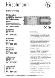
Montageanleitung<br />
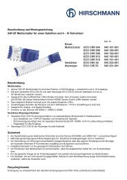
SAT-ZF Multischalter<br />
4 Sat-ZF-Eingänge für<br />
<strong>24</strong> - <strong>32</strong> Teilnehmer<br />
<strong>CKR</strong> 5<strong>24</strong>1 940-159-001<br />
<strong>CKR</strong> 5<strong>32</strong>1 940-160-001<br />
Beschreibung<br />
• aktiver SAT-ZF-Multischalter mit 4 SAT-Eingängen für <strong>24</strong> und <strong>32</strong> SAT-Receiver<br />
• eingebauter 22kHz Generator zum Einsatz an Quattro „S“ LNCs<br />
• zusätzliche Einspeisung terrestrischer Signale (regelbar)<br />
• aktiver Rückkanal 5 - 65 MHz<br />
• geeignet für alle üblichen LNCs<br />
• terr. Vorwärtspfad in Push-Pull-Technik mit Pegelsteller<br />
• das integrierte Netzteil versorgt auch die angeschlossenen LNCs<br />
• unabhängiges Schalten der Receiver auf die 4 SAT-Ebenen<br />
Auswahlkriterium: 13 / 18 V, Schaltfrequenz 0 / 22 kHz<br />
• geeignet für Analog- und Digital-Empfang (terrestrisch DVB-T und SAT)<br />
Die angegebenen max. Ausgangspegel an den Teilnehmerausgängen sind einzuhalten, da es sonst<br />
zu Bildstörungen kommen kann.<br />
Technische Daten :<br />
Frequenzbereich, SAT 950 - <strong>24</strong>00 MHz<br />
Max. Ausg.-Pegel (35 dB IMA3) 90 dBµV<br />
Entkopplung H/V > 20 dB<br />
Frequenzbereich, terrestrisch 80 - 862 MHz<br />
Max. Ausg.-Pegel (60 dB IMA2) 76 dBµV<br />
Max. Ausg.-Pegel (60 dB IMA3) 85 dBµV<br />
Frequenzbereich, Rückkanal 5 - 65 MHz<br />
Max. Ausg.-Pegel (60 dB IMA3) 112 dBµV<br />
Entkopplung, Rec-Rec > 25 dB<br />
Netzteil 94 … 265 V~ / 47-63 Hz, 26 W<br />
Max. Stromabgabe (LNB) 500 mA<br />
Abmessungen L x B x H<br />
450 x 125 x 80 mm<br />
<strong>CKR</strong> 5<strong>24</strong>1 <strong>CKR</strong> 5<strong>32</strong>1<br />
Ausgänge <strong>24</strong> <strong>32</strong><br />
Dämpfung (Rückkanal) 13 +/-2 14 +/- 2 dB<br />
Verstärkung (terr.) 1 +/-2 0 +/- 2 dB<br />
Verstärkung (SAT-ZF) 1 +/-2 1 +/- 2 dB<br />
Steuersignal ASTRA analog / digital ASTRA / EUTELSAT<br />
13 V / 0 kHz Vertikal / low Vertikal / low ASTRA<br />
18 V / 0 kHz Horizontal / low Horizontal / low ASTRA<br />
13 V / 22 kHz Vertikal / high Vertikal / low EUTELSAT<br />
18 V / 22 kHz Horizontal / high Horizontal / low EUTELSAT<br />
50/51135.00 01/2006<br />
Sicherheit<br />
Die VDE-Bestimmungen 0100 und 0855 Teil 1 bzw. die Europanormen EN50083 Teil 1 zur<br />
Gewährleistung der elektrischen Sicherheit sind zu berücksichtigen!<br />
Nationale genehmigungsrechtliche Regelungen für Rundfunk-Empfangsanlagen sind zu beachten!<br />
Zur Vermeidung von Störungen benachbarter Anlagen/Systeme oder des eigenen Empfangs ist die<br />
Montage der koaxialen Verbinder (F-Connectoren) sorgfältig und fachgerecht durchzuführen.<br />
Hierbei sind Kurzschlüsse zu vermeiden.<br />
Vor Öffnen Netzstecker ziehen. Installationsarbeiten nur bei gezogenem Netzstecker durchführen.<br />
Vor Einstecken des Netzsteckers ist sicherzustellen, daß die angebrachten Kabel frei von<br />
Kurzschlüssen sind.<br />
Montage<br />
Der Multischalter ist mit den beiliegenden Schrauben an vor Feuchtigkeit geschützter und ebener<br />
Fläche zu montieren. Der Montageuntergrund sollte schwer entflammbar sein.<br />
Die Montage soll möglichst in Standortnähe der SAT-Antenne erfolgen.<br />
Unbenutzte Ein- bzw. Ausgänge müssen mit einem Endwiderstand abgeschlossen<br />
werden.<br />
Hirschmann Multimedia<br />
Electronics GmbH<br />
Stuttgarter Str. 45-51<br />
D-72654 Neckartenzlingen<br />
Phone:+49 (0) 180 <strong>32</strong> <strong>32</strong>-341<br />
www.hirschmann.com
Installation manual<br />
Multiswitch with<br />
4 Sat-IF-inputs<br />
for <strong>24</strong> - <strong>32</strong> subscribers<br />
<strong>CKR</strong> 5<strong>24</strong>1 940-159-001<br />
<strong>CKR</strong> 5<strong>32</strong>1 940-160-001<br />
Description<br />
• active SAT-IF-Multiswitch with 4 SAT-inputs for <strong>24</strong> and <strong>32</strong> SAT-receivers<br />
• with additional 22 kHz-generator for use with Quattro „S“ LNBs<br />
• additional feed-in for terrestrial signals (with variable attenuator)<br />
• active return path 5 - 65 MHz<br />
• suitable for all usual LNBs<br />
• terrestrial forward path with push-pull amplifier and variable attenuator<br />
• the integrated power-pack supplies the SEM and the connected LNBs<br />
• independent switching of the receiver to each of the 4 satellite polarizations<br />
switching criteria: 13 / 18 V, switch tone 0 / 22 kHz<br />
• suitable for analogue and digital reception (terrestrial DVB-T and SAT)<br />
switching criteria ASTRA analogue / digital ASTRA / EUTELSAT<br />
13 V / 0 kHz Vertikal / low Vertikal / low ASTRA<br />
18 V / 0 kHz Horizontal / low Horizontal / low ASTRA<br />
13 V / 22 kHz Vertikal / high Vertikal / low EUTELSAT<br />
18 V / 22 kHz Horizontal / high Horizontal / low EUTELSAT<br />
Security<br />
Repair and maintenance should only be done by skilled technicians and TV and radio specialists.<br />
The applicable European Standards and national requirements to ensure electrical security have to<br />
be obeyed. Likewise national standards and requirements for radio and TV receiving installations.<br />
Both the input level of the terrestrial and the SAT-IF-signals should be in the recommended ranges<br />
to avoid interference.<br />
Technical data:<br />
Frequency range SAT-IF 950 - <strong>24</strong>00 MHz<br />
Max. Output level (35 dB IMA3) 90 dBµV<br />
Isolation H/V > 20 dB<br />
Frequency range terrestrial 80 - 862 MHz<br />
Max. Output level (60 dB IMA2) 76 dBµV<br />
Max. Output level (60 dB IMA3) 85 dBµV<br />
Frequency range return path 5 - 65 MHz<br />
Max. Output level (60 dB IMA3) 112 dBµV<br />
Isolation, Rec-Rec > 25 dB<br />
Power supply unit (Switch-mode PSU) 94 … 265 V~ / 47-63 Hz, 26 W<br />
Max. current supply (to LNB) 500 mA<br />
Dimensions L x W x H<br />
450 x 125 x 80 mm<br />
<strong>CKR</strong> 5<strong>24</strong>1 <strong>CKR</strong> 5<strong>32</strong>1<br />
Outputs <strong>24</strong> <strong>32</strong><br />
Tap loss (return path) 13 +/-2 14 +/- 2 dB<br />
Tap gain (terrestrial) 1 +/-2 0 +/- 2 dB<br />
Tap gain (SAT-IF) 1 +/-2 1 +/- 2 dB<br />
Installation<br />
All installation and fixing of components should only be executed when the units are disconnected from<br />
the mains supply.<br />
The surface and environment of installation should be<br />
- even and dust-free<br />
- protected against humidity<br />
- flame proof<br />
- not under direct impact of sunlight<br />
- not adjacent to heating sources<br />
Ventilation slots should be kept open and suitable circulation of fresh air should be ensured.<br />
The installation has to be careful and skilful.<br />
Short-circuits have to be avoided. Only F- connectors matching with the used coaxial cable should be<br />
used. Not connected outputs of distribution units should be terminated with 75 Ohm termination<br />
resistors.<br />
In order to split the terrestrial signals and the satellite-IF-signals again, antenna sockets should be<br />
installed.<br />
The maximum output level at the receiver outputs mentioned should be adhered to in order to avoid<br />
picture disturbances.<br />
Hirschmann Multimedia<br />
Electronics GmbH<br />
Stuttgarter Str. 45-51<br />
D-72654 Neckartenzlingen<br />
Phone:+49 (0) 180 <strong>32</strong> <strong>32</strong>-341<br />
www.hirschmann.com