CKR 9xxx
CKR 9xxx
CKR 9xxx

You also want an ePaper? Increase the reach of your titles
YUMPU automatically turns print PDFs into web optimized ePapers that Google loves.
Neunkabelsystem<br />
DiSEqC TM -Profi-Multischalter<br />
für Verteilsysteme<br />
<strong>CKR</strong> 9120 ND<br />
Bestell-Nr.:<br />
947 685 - 002<br />
<strong>CKR</strong> 9160 ND<br />
Bestell-Nr.:<br />
947 686 - 002<br />
01- 0400<br />
50/51072.59-v1<br />
Deutsch: Seite 1 / English: page 13<br />
Hirschmann<br />
Multimedia Electronics GmbH<br />
Stuttgarter Strasse 45 - 51<br />
D- 72654 Neckartenzlingen<br />
Telefon : 07127 14 - 0
Bedienungsanleitung<br />
Inhaltsverzeichnis<br />
Seite<br />
DiSEqC TM 2.0 - Multischalter<br />
für SAT-ZF-Verteilsysteme<br />
Type: <strong>CKR</strong> 9120 ND<br />
<strong>CKR</strong> 9160 ND<br />
1. Anwendungsbeschreibung<br />
1. Anwendungsbeschreibung 3<br />
2. Systemstruktur 3<br />
3. Inneneinheit 4<br />
3.1 Multischalter (<strong>CKR</strong> 9120 / 9160 ND) 4 - 6<br />
3.2 Schaltereinstellungen 5<br />
4. Planungs- und Installationshinweise 7 - 8<br />
5. Sicherheitshinweise 8<br />
6. Anlagenbeispiele 8 - 10<br />
7. Hilfe bei der Fehlersuche 11 - 12<br />
Die DiSEqC - Multischalter <strong>CKR</strong> 9120 ND und <strong>CKR</strong> 9160 ND sind zur Verteilung von terrestrischen- und<br />
Sat-ZF-Antennensignalen bestimmt.<br />
Die Bauteile können einzeln oder in der Zusammenschaltung mit Eingangsverteilern verwendet werden.<br />
Dabei können von jedem Teilnehmer (Receiver) die Programme von 8 Sat-ZF-Ebenen und des terrestrischen<br />
Bandes, einschließlich UKW, empfangen werden.<br />
Es spielt hierbei keine Rolle, ob die Programme analog oder digital übertragen werden.<br />
Der breitbandige terrestrische Eingang ist BK-tauglich und zukunftsicher mit einem Daten-Rückkanal<br />
ausgestattet.<br />
Es können aber auch über einen selektiven Mehrbereichverstärker, geführte terrestrische Antennensignale<br />
eingespeist werden.<br />
Somit ist das System auch für Multimedianwendungen wie z.B. ASTRA-NET, Direct-PC, Net on Air,<br />
etc. vorbereitet<br />
2. Systemstruktur<br />
Die Anlage besteht aus der Außeneinheit, d.h. einer oder mehrerer Satellitenantennen mit diversen LNB´s,<br />
sowie der Inneneinheit, die sich aus den Hirschmann Verteilkomponenten zusammensetzt.<br />
Die Inneneinheiten werden als Sternverteilung installiert.<br />
An zentralen geografischen Orten der Satellitenausleuchtzonen werden Antennen mit Spiegeldurchmessern<br />
ab 80 cm empfohlen.<br />
Größere Spiegeldurchmesser verbessern allgemein das S/N (Signal/Rauschverhälnis) und damit die<br />
Schlechtwetterreserve.<br />
Bitte lesen Sie vor der Installation diese Anleitung aufmerksam<br />
durch und beachten besonders die Sicherheitshinweise auf<br />
Seite 8 !<br />
In Bereichen mit schwächeren Empfangsfeldstärken sollte der Spiegeldurchmesser mindestens 1m betragen.<br />
Zum Anschluß an die Anlage eignen sich Dual-,Twin-, Quatro- und Universal Quatro S- LNB´s.<br />
Dabei ist besonders auf ein geringes Rauschmaß der LNB´s zu achten. Der Ausgangspegel am LNB sollte<br />
75 dBµV nicht unterschreiten.<br />
Für Standardanwendungen (Analog und Digital-Empfang von ASTRA und EUTELSAT) sollten vorzugsweise<br />
Quatro-LNB´s eingesetzt werden.<br />
2<br />
3
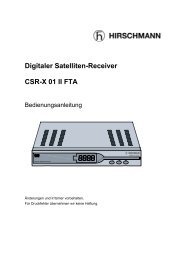
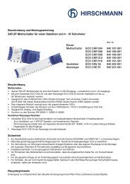
3. Inneneinheit<br />
3.1 Multischalter (<strong>CKR</strong> 9120 / 9160 ND)<br />
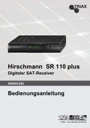
3.2 Multischalter <strong>CKR</strong> 9160 ND<br />
Schaltereinstellungen<br />
Der Multischalter ist die Zentrale Umschalteinheit für die Antennensignale.<br />
Das angedockte Netzteil versorgt die gesamte Anlage.<br />
22 kHz-<br />
High-Eing.<br />
Generator<br />
Aus Ein<br />
LNB - Versorgungsspannungen<br />
Position A<br />
Position B<br />
Low High Low High<br />
vert. hor. vert. hor. vert. hor. vert. hor.<br />
LNB - Typen<br />
13 V 18 V 13 V 18 V 13 V 18 V 13 V 18 V<br />
0 kHz 0 kHz 22 kHz 22 kHz 0 kHz 0 kHz 22 kHz 22 kHz<br />
Quatro - Universal - Switch<br />
13 V 18 V 13 V<br />
0 kHz 0 kHz 0 kHz<br />
18 V<br />
0 kHz<br />
13 V<br />
0 kHz<br />
18V 13 V 18 V<br />
0 kHz 0 kHz 0 kHz<br />
Werkseinstellung : Twin / Quatro usw.<br />
<strong>CKR</strong> 9120 ND<br />
(für 12 Receiver)<br />
<strong>CKR</strong> 9160 ND<br />
(für 16 Receiver)<br />
47-862 MHz<br />
-20 dB<br />
Rec. 1 - 16<br />
950-2300MHz<br />
-10 dB<br />
Kontrolllampe auf der<br />
Netzteil - Leiterplatte<br />
Der Multischalter bietet folgende Besonderheiten:<br />
Multischalter 9 in 16<br />
Multiswitch 9 in 16<br />
Multiswitch 9 en 16<br />
????????? 8 Sat-ZF-Eingänge und 1 terrestrischer Eingang<br />
???????? Je nach Typ 12, 16 Teilnehmer-Ausgänge (Receiveranschlüsse)<br />
???????? Unterstützt den Steuersignalstandard DiSEqC -Standards bis Level 2.0<br />
???????? Arbeitet auch mit den Steuersignalen 13V/18V, 0/22kHz, Tonburst mod./ unmod.<br />
22 kHz - Schaltfunktion<br />
Function of 22 kHz signal<br />
Band Position Band Position EIN<br />
L / H A / B L / H A / B on<br />
Rec 16 Rec 15<br />
22 kHz -<br />
Generator<br />
AUS<br />
off<br />
f /MHz<br />
Attenuation/dB<br />
2. Ord./dBµV 3. Ord./dBµV<br />
IMA<br />
??<br />
60dB IMA<br />
?? 60dB<br />
5 - 30 28<br />
-<br />
-<br />
47 -862 3±2<br />
77<br />
92<br />
950 - 2400<br />
6±2<br />
-<br />
-<br />
3. Ord./dBµV<br />
Isolation<br />
I max./mA<br />
I max./mA<br />
IMA<br />
?<br />
35dB<br />
(H/V) /dB<br />
LNB (13V/18V)<br />
LNB (13V)<br />
-<br />
-<br />
-<br />
-<br />
102<br />
>25<br />
500/1200<br />
1200<br />
94 … 265V~/ 60/60Hz 38VA Made in Germany<br />
Rückkanaltauglich<br />
with return path<br />
Vo r Öff nen Netzstecker ziehe n!<br />
Unbenutzte Ein- und Ausgänge<br />
Disconn ect ma in s be fore rem oving co ver!<br />
sind mit 75 Ohm abzuschließen!<br />
Vor Feuchtigkeit schützen!<br />
Not used inputs and outputs<br />
Nicht zulässig i n Empfangsstellen!<br />
should be term inated with 75 ohms!<br />
Cauti on! For indoor use only!<br />
Vor Öffnen des Gerätes Netzstecker ziehen! Vor Feuchtigkeit schützen!<br />
Disconnect from mains before opening! Protect against humidity!<br />
Coupler le courant avant d’ouvrir!<br />
Défendre contre l’humidité!<br />
Netzanschluß<br />
92...264 V ~<br />
???????? Die 4 Eingänge auf Sat-Position B besitzen je einen Pegelsteller<br />
???????? In Teilnehmerrichtung befindet sich ein gemeinsam pegelbarer terrestrischer Verteilverstärker<br />
???????? Mit Daten-Rückkanal (5...30MHz)<br />
???????? Variable LNB-Versorgung mit Spannungsumschaltung und 22kHz-Generator (Siehe Seite 5)<br />
Vom Receiver :<br />
DiSEqC oder<br />
13/18 V,<br />
0/22 kHz,<br />
Tonburst<br />
mod / unmod<br />
22 kHz-<br />
Wahlschalter<br />
Rec 1-6<br />
0 kHz 22 kHz<br />
Pos. A<br />
Pos. B<br />
???????? 22kHz-Funktionsschalter für zwei Teilnehmer (Umschaltung Band Low/High oder Position A/B)<br />
Band Low<br />
Band High<br />
???????? Schaltnetzteil mit Weitbereichseingang (94...264V~)<br />
4<br />
5
Technische Daten:<br />
4. Planungs- und Installationshinweise<br />
Type: <strong>CKR</strong> 9120 ND<br />
Eingänge / Ausgänge 9 / 12<br />
Frequenzbereich 5 - 30 47 - 862 950 - 2400 MHz<br />
Dämpfung 26 1 +/-2 6 +/-2 dB<br />
Max. Ausg.-Pegel (60 dB IMA 2<br />
) - 79 - dBµV<br />
Max. Ausg.-Pegel (60 dB IMA 3<br />
) - 92 - dBµV<br />
Max. Ausg.-Pegel (35 dB IMA 3<br />
) - - 102 dBµV<br />
Entkopplung H/V - - >25 dB<br />
Max. Stromabgabe an LNBs (13V/18V) 500 / 1200 mA<br />
Type: <strong>CKR</strong> 9160 ND<br />
Eingänge / Ausgänge 9 / 16<br />
Frequenzbereich 5 - 30 47 - 862 950 - 2400 MHz<br />
Dämpfung 28 3 +/-2 6 +/-2 dB<br />
Max. Ausg.-Pegel (60 dB IMA 2<br />
) - 77 - dBµV<br />
Max. Ausg.-Pegel (60 dB IMA 3<br />
) - 92 - dBµV<br />
Max. Ausg.-Pegel (35 dB IMA 3<br />
) - - 102 dBµV<br />
Entkopplung H/V - - >25 dB<br />
Max. Stromabgabe an LNBs (13V/18V) 500 / 1200 mA<br />
Die Planung einer Verteilanlage für terrestrische- und Sat-ZF-Signale hängt stark von den örtlichen<br />
Gegebenheiten ab. Folgende Strukturen sind möglich:<br />
??? Gestreckter Aufbau mit mehreren Sternverteilungen<br />
??? Zentraler Aufbau mit einer Sternverteilung<br />
Beim gestreckten Aufbau sind die Baugruppen voneinander entfernt installiert. Es können sich Multischalter<br />
in jeder Etage befinden, die durch 5-10 m lange Strangleitungen verbunden sind.<br />
Es folgen dann noch die 20-30m langen Teilnehmerleitungen bis zur Antennendose (siehe Seite 10).<br />
Beim zentralen Aufbau ist die Anlage an einem Ort montiert, z.B. in Keller oder Dachboden, von wo aus z.T.<br />
sehr lange Teilnehmerleitungen (>30 m) bis zur Antennendose folgen (siehe Seite 9).<br />
Das Erstellen eines Pegelplanes ist sinnvoll. Dabei müssen die Pegel für den terrestrischen- und den Sat-<br />
Bereich getrennt betrachtet werden.<br />
Ausgehend von der Antennendose mit der größten Entfernung zur Antenne werden die Signalpegel vom<br />
Mindestwert zurückgerechnet.<br />
Minimale und maximale Trägerpegel am Teilnehmeranschluss (Antennensteckdose)<br />
Frequenzbereich minimal maximal<br />
SAT-ZF 950 -2400 MHz 47 77 dBµV<br />
terr. 47 - 862 MHz 57 77 dBµV<br />
Wichtiger Hinweis !<br />
Sollte der 22 kHz - Wahlschalter während des Betriebes einmal umgeschaltet werden müssen,<br />
so wird diese Änderung von der Teilnehmerschaltung erst erkannt, nachdem der Receiver seine<br />
LNB-Versorgung einmal unterbrochen, oder ein „Reset“-Kommando gesendet hat.<br />
Achtung! Manche Receiver liefern im Standby-Modus weiterhin die LNB-Versorgung. In diesem<br />
Fall muß der Receiver kurz von der Netzspannung getrennt werden.<br />
Die Funktion des 22kHz-Wahlschalters ist außer Kraft gesetzt, sobald der Receiver DiSEqC<br />
Signale sendet, denn diese haben Vorrang.<br />
Durch lange Kabelstrecken entstehen Verzerrungen, d.h. bei niedrigen Frequenzen hat das Kabel geringe<br />
Dämpfung, bei hohen Frequenzen eine hohe Dämpfung.<br />
So entsteht eine Pegelschräglage, die durch einen Entzerrer oder einen entzerrten Verstärker ausgeglichen<br />
werden kann.<br />
Das Netzteil eines Multischalters liefert die Spannungen 13 und 18 Volt für die Speisung der LNB`s.<br />
Je nach LNB-Typ beträgt Strombedarf 200 - 450 Milliampere pro LNB.<br />
Bei Betrieb von Universal Quatro Switch LNB´s kann am 22kHz-Schalter im Multischalter für die High-<br />
Band-Eingänge ein 22kHz-Schaltsignal zugeschaltet werden, um vom LNB das gewünschte Band zu empfangen.<br />
6<br />
7
Wichtiger Hinweis !<br />
.<br />
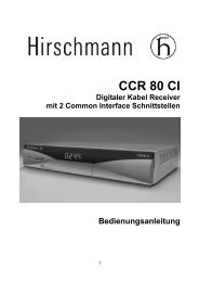
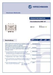
Beispiel : SAT-ZF-Verteilanlage mit terrestrischer Einspeisung<br />
Nichtbenutzte Ein-und Ausgänge müssen mit 75 Ohm Abschlußwiderständen abgeschlossen<br />
werden.<br />
5. Sicherheitshinweise<br />
? Vor Öffnen Netzstecker ziehen!<br />
? Installationsarbeiten nur bei gezogenem Netzstecker durchführen.<br />
? Die VDE-Bestimmungen 0100 und 0855 Teil 1 bzw. die Europanormen EN 50083 Teil 1 zur Gewährleistung<br />
der elektrischen Sicherheit sind zu berücksichtigen!<br />
? Nationale genehmigungsrechtliche Regelungen für Rundfunk-Empfangsanlagen sind zu beachten!<br />
<strong>CKR</strong> 9160 ND<br />
? Die Anlagenteile sind zu erden und gemäß o.a. Bestimmungen gegen Blitzschlag zu schützen.<br />
? Die Bauteile sind an trockenen gut belüfteten Orten auf ebener schwer entflammbarer Unterlage<br />
zu montieren. Umgebungstemperaturen über 55° C sind zu vermeiden.<br />
? Zur Vermeidung von Störungen benachbarter Anlagen/Systeme oder des eigenen Empfangs ist die<br />
Montage der koaxialen Verbinder (F-Connectoren) sorgfältig und fachgerecht durchzuführen. Hierbei<br />
sind Kurzschlüsse zu vermeiden !<br />
? Bei Inbetriebnahme der Anlage leuchtet im Netzgerät eine grüne Kontrollampe dauerhaft auf.<br />
(Durch die Kühlschlitze des Netzgerätes einsehbar)<br />
? Leuchtet die Kontrolllampe nicht oder blinkt nur, sofort Netzstecker ziehen und Kurzschluß in der<br />
Anlage suchen und beseitigen.<br />
Für Schäden, die auf nicht bestimmungsgemäßen Gebrauch oder Nichtbeachtung obiger Sicherheitshinweise<br />
entstehen, haftet der Hersteller nicht.<br />
6. Anlagenbeispiele<br />
SAT-ZF-Verteilanlage mit terrestrischer Einspeisung (siehe Seite 9).<br />
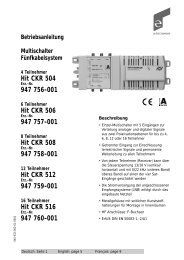
Anlagenbeispiel für 64 Teilnehmer (siehe Seite 10).<br />
8<br />
9
Anlagenbeispiel für 64 Teilnehmer<br />
7. Hilfe bei der Fehlersuche<br />
Fehler:<br />
Kein Empfang mit Analog- oder Digital-Receiver evtl. auch kein terrestrischer Empfang!<br />
Nach Inbetriebnahme der Anlage leuchtet die Kontrolllampe im Netzgerät nicht, oder blinkt nur.<br />
Grund:<br />
a) Keine 230 V~ Netzspannung vorhanden.<br />
b) Eine Überlastung oder ein Kurzschluß an den Eingängen liegt vor!<br />
Abhilfe:<br />
a) Für ausreichend Netzspannung sorgen.<br />
b) Während der Multischalter in Betrieb bleibt, werden nacheinander die Antennenzuleitungen hiervon<br />
entfernt bis die Kontrolllampe im Netzgerät durchgehend leuchtet.<br />
Hinweis !<br />
Die 8 Antennenleitungen in Richtung der LNB´s sind alle spannungsführend.<br />
Fehler:<br />
Kein Bild, obwohl die Versorgungsspannungen zu den LNB´s und zur Anlage überprüft und in<br />
Ordnung sind.<br />
Grund:<br />
a) Empfangssignale vom LNB fehlen.<br />
b) Falsche Antennendosen installiert.<br />
c) Bei Verwendung von Universal Quatro Switch LNB´s:<br />
Die für den Betrieb im High-Band erforderlichen 22kHz auf der Versorgungsspannung fehlen.<br />
Abhilfe:<br />
a) Antenne ausrichten bzw. defekten LNB austauschen,Versorgungsspanungendirekt am LNB um<br />
Leitung auf Kabelbruch prüfen.<br />
b) Die richtigen Antennendosen anschließen.<br />
c) 22kHz-Generator einschalten (siehe Seite 5).<br />
Fehler:<br />
Die terrestrischen Fernsehkanäle (47-862 MHz) sind gestört (Rauschen oder Moiré im Bild).<br />
Grund:<br />
Die Signalpegel innerhalb der Anlage sind nicht ordnungsgemäß eingestellt.<br />
Abhilfe:<br />
Es ist ein Pegelplan wie beschrieben aufzustellen, und die Signalpegel unter Zuhilfenahme eines Antennenmeßgerätes<br />
einzustellen.<br />
Dabei ist darauf zu achten, daß der Betriebspegel am jeweiligen Anlagenteil unter Berücksichtigung der<br />
übertragenen Kanalanzahl nicht überschritten wird.<br />
10<br />
11
Fehler:<br />
An einer Anlage mit Antennen für ASTRA (auf Pos A und EUTELSAT (auf Pos. B) mit Low- und<br />
High-Band empfängt ein Analog-Receiver (ohne DiSEqC? ) nur das Low-Band von ASTRA, also<br />
nur Position A.<br />
Grund:<br />
a) Der Receiver liefert kein 22kHz-Schaltsignal, wenn auf EUTELSAT geschaltet werden soll.<br />
b) Der zugehörige 22kHz-Wahlschalter an dem angeschlossenen Anlagenbaustein steht<br />
nicht auf Position A/B.<br />
c) Bei der Installation sind Antennenleitungen zum LNB miteinander vertauscht worden.<br />
Abhilfe:<br />
a) Receiver nach Herstelleranleitung auf 22kHz-Steuerung programmieren.<br />
b) Den zugehörigen 22kHz-Wahlschalter am Anlagenbaustein auf Position A/B stellen und beachten,<br />
daß bei Änderungen am 22 kHz-Wahlschalter der Receiver danach kurz von der Netzspannung zu<br />
trennen ist (siehe Seite 6 “Wichtiger Hinweis!”).<br />
c) Vertauschungen der Antennenleitungen zum LNB beseitigen.<br />
9 - cable system<br />
DiSEqC TM -Profi-Multiswitches<br />
for cascadable systems<br />
Fehler:<br />
An einer Anlage mit Antennen für ASTRA (auf Pos A)und EUTELSAT (auf Pos B) mit Low- und<br />
High-Band empfängt ein Digital-Receiver (ohne DiSEqC? ) nur wenige oder gar keine Programme.<br />
Grund:<br />
a) Der Receiver liefert kein 22kHz-Schaltsignal, um in das High-Band schalten zu können.<br />
b) Der zugehörige 22kHz-Wahlschalter an dem angeschlossenen Anlagenbaustein steht<br />
nicht auf Band High/Low.<br />
c) Bei der Installation sind Antennenleitungen zum LNB miteinander vertauscht worden.<br />
<strong>CKR</strong> 9120 ND<br />
Order no.:<br />
947 685 - 002<br />
Abhilfe:<br />
a) Receiver nach Herstelleranleitung auf 22kHz-Steuerung programmieren.<br />
b) Den zugehörigen 22kHz-Wahlschalter am Anlagenbaustein auf Band High/Low stellen und<br />
beachten, daß bei Änderungen am 22kHz-Wahlschalter der Receiver danach kurz von der<br />
Netzspannung zu trennen ist. (siehe Seite 6 “Wichtiger Hinweis!”)<br />
c) Vertauschungen der Strangkabel beseitigen.<br />
<strong>CKR</strong> 9160 ND<br />
Order no.:<br />
947 686 - 002<br />
Änderungen und Irrtümer bleiben vorbehalten.<br />
DiSEqC TM ist ein eingetragenes Warenzeichen von Eutelsat. 09/2003<br />
English<br />
Hirschmann<br />
Multimedia Electronics GmbH<br />
Stuttgarter Strasse 45 - 51<br />
D- 72654 Neckartenzlingen<br />
Telefon : 07127 14 - 0<br />
12<br />
13
Product manual<br />
Table of contents<br />
Page<br />
DiSEqC TM 2.0 - Profi - multiswitches<br />
for cascadable systems<br />
Type: <strong>CKR</strong> 9120 ND<br />
<strong>CKR</strong> 9160 ND<br />
1. General description<br />
1. General description 15<br />
2. Structure of the system 15<br />
3. Indoor units 16<br />
3.1 Multiswitch (<strong>CKR</strong> 9120 / 9160 ND) 16 - 18<br />
3.2 Switch configurations 17<br />
4. Planning, installation and fixing remarks 19 - 20<br />
5. Safety notes 20<br />
6. Installation examples 21 - 22<br />
7. What to do in case of problems 23 - 24<br />
The cascadable DiSEqC TM - Multiswitch <strong>CKR</strong> 9120 and <strong>CKR</strong> 9160 ND has been designed for the<br />
distribution of terrestrial and satellite IF antenna signals.<br />
Units can either be used individually or when interconnected as a cascadable system.<br />
Each subscriber (connected satellite receiver) can receive programs from 8 satellite-IF polarizations and<br />
the terrestrial range including FM-radio.<br />
It does not matter whether programs are digital or analogue.<br />
The broadband terrestrial input can be used for CATV signals and it incorporates a data return path.<br />
With this the system is likewise suitable for multimedia applications such as ASTRA-NET, Direct-PC<br />
Net-on-air etc.<br />
2. Structure of the system<br />
A complete system consists of an outdoor unit, i.e. one or more satellite antennas with various LNBs, and an<br />
indoor unit, consisting of various components.<br />
The indoor units can be installed in a star distribution structure.<br />
In geographically central locations of the satellite foot-print satellite dishes with diameters of not less than<br />
80 cm are recommended.<br />
Bigger diameters of dish antennas improve the S/N (Signal to noise ratio) and thus the reserve in bad<br />
weather conditions.<br />
In areas with weaker reception levels the satellite dish diameter should be minimum 1,00 meter.<br />
Important !<br />
Prior to the installation and fixing of this system make sure that<br />
you have read this product manual carefully and that you duly noted<br />
all safety notes on page 20.<br />
The suitable LNB types for the connection to the cascadable system are Dual-, Twin, Quatro- and Universal<br />
Quatro (switchable) - types.<br />
A low noise figure of the used LNBs is important. The output level at the output of the LNB should not be<br />
less than 75dBµV.<br />
For standard applications (analogue and digital reception of ASTRA and EUTELSAT) Quatro LNBs are<br />
preferable.<br />
14<br />
15
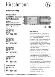
3. Indoor unit<br />
3.1 Multiswitch (<strong>CKR</strong> 9120 / 9160 ND)<br />
3.2 Multiswitch <strong>CKR</strong> 9160 ND<br />
Switch configurations<br />
The Multiswitch is the central switching unit for the antenna signals. The power supply unit supplies hole<br />
system.<br />
LNB supply voltages<br />
LNB - Types<br />
22 kHzgenerator<br />
High input<br />
out / in<br />
Position A<br />
Position B<br />
Low High Low High<br />
vert. hor. vert. hor. vert. hor. vert. hor.<br />
13 V 18 V 13 V 18 V 13 V 18 V 13 V 18 V<br />
0 kHz 0 kHz 22 kHz 22 kHz 0 kHz 0 kHz 22 kHz 22 kHz<br />
Quatro - Universal - Switch<br />
13 V 18 V<br />
0 kHz 0 kHz<br />
13 V 18 V<br />
0 kHz 0 kHz<br />
13 V 18V 13 V 18 V<br />
0 kHz 0 kHz 0 kHz 0 kHz<br />
Factory pre-setting : Twin / Quatro<br />
<strong>CKR</strong> 9120 ND<br />
(für 12 Receiver)<br />
The Multiswitch has the following features:<br />
<strong>CKR</strong> 9160 ND<br />
(für 16 Receiver)<br />
Function LED on power supply PCB<br />
visible through ventilation slots<br />
? 8 satellite-IF-inputs and 1 terrestrial input<br />
Multischalter 9 in 16<br />
Multiswitch 9 in 16<br />
Multiswitch 9 en 16<br />
? According to the available type 12, 16 subscriber outputs (connected satellite<br />
receivers)<br />
? It supports the DiSEqC TM - standards up to level 2.0<br />
f /MHz<br />
Attenuation/dB 2. Ord./dBµV<br />
3. Ord./dBµV<br />
IMA<br />
?? 60dB<br />
IMA<br />
??<br />
60dB<br />
5 - 30<br />
33<br />
-<br />
-<br />
47 -862<br />
10 ±<br />
2<br />
77<br />
92<br />
950 - 2400<br />
8±2<br />
-<br />
-<br />
3. Ord./dBµV<br />
Isolation<br />
I max./mA<br />
I max./mA<br />
IMA<br />
?<br />
35dB<br />
(H/V) /dB<br />
LNB (13V/18V)<br />
LNB (13V)<br />
-<br />
-<br />
-<br />
-<br />
102<br />
>25<br />
500/1200<br />
1200<br />
94 … 265V~/ 60/60Hz 38VA Made in Germany<br />
Vor Öffnen des Gerätes Netzstecker ziehen! Vor Feuchtigkeit schützen!<br />
Disconnect from mains before opening! Protect against humidity!<br />
Coupler le courant avant d’ouvrir!<br />
Défendre contre l’humidité!<br />
? It also works with the commanding signals 13V/18V, 0/22kHz, Toneburst mod/unmod.<br />
? The 4 inputs of Sat-position B each have a level adjuster.<br />
Band<br />
L / H<br />
22 kHz - Schaltfunktion<br />
Function of 22 kHz signal<br />
Position<br />
A / B<br />
Band<br />
L / H<br />
Rec 16 Rec 15<br />
Position<br />
A / B<br />
Rückkanaltauglich<br />
with return path<br />
EIN AUS<br />
on off<br />
Unbenutzte Ein- und A usgänge<br />
sind mit 7 5 Ohm a bzus chlie ßen !<br />
No t used inp uts and outputs<br />
should be terminated with 75 ohms!<br />
22 kHz -<br />
Generator<br />
Vor Öffnen Netzstecker ziehen!<br />
Disconnect mains before removing cover!<br />
Vor Feuchtigkeit schüt zen!<br />
Nicht zuläss ig in Em pfangsst ellen!<br />
Caution! For indoor use only!<br />
Power connection<br />
92...264 V ~<br />
? In the direction of the subscribers there is a jointly adjustable distribution amplifier.<br />
? With passive data return channel (5...30 MHz)<br />
? Variable LNB supply with voltage switch function and 22kHz generator (details on<br />
(page 17)<br />
From receiver :<br />
DiSEqC or<br />
13/18 V,<br />
0/22 kHz,<br />
Tonburst<br />
mod ./ unmod.<br />
22 kHzselector<br />
switch<br />
Rec 1-6<br />
0 kHz 22 kHz<br />
? 22-kHz function-switch for two subscriber (switching of Band Low/High or<br />
Position A/B)<br />
? Switch-mode-power supply (94...264 VAC)<br />
Pos. A<br />
Band Low<br />
Pos. B<br />
Band High<br />
16<br />
17
Specifications:<br />
4. Planning, installation and fixing notes<br />
Type <strong>CKR</strong> 9120 ND<br />
Inputs / Outputs 9 / 12<br />
Frequency range 5 - 30 47 - 862 950 - 2400 MHz<br />
Attenuation 26 1 +/-2 6 +/-2 dB<br />
Max. output level (60 dB IMA 2<br />
) - 79 - dBµV<br />
Max. output level (60 dB IMA 3<br />
) - 92 - dBµV<br />
Max. output level (35 dB IMA 3<br />
) - - 102 dBµV<br />
Isolation H/V - - >25 dB<br />
Max. power to LNBs (13V/18V) 500 / 1200 mA<br />
Type <strong>CKR</strong> 9160 ND<br />
Inputs / Outputs 9 / 16<br />
Frequency range 5 - 30 47 - 862 950 - 2400 MHz<br />
Attenuation 28 3+/-2 6 +/-2 dB<br />
Max. output level (60 dB IMA 2<br />
) - 77 - dBµV<br />
Max. output level (60 dB IMA 3<br />
) - 92 - dBµV<br />
Max. output level (35 dB IMA 3<br />
) - - 102 dBµV<br />
Isolation H/V - - >25 dB<br />
Max. power to LNBs (13V/18V) 500 / 1200 mA<br />
The planning of a distribution system for both terrestrial- and satellite-IF signals largely depends on the local<br />
conditions. The following structures are possible:<br />
? stretched structure possibly with several trunks<br />
? central structure (star distribution system)<br />
In a stretched structure the individual components will be installed separated from each other.<br />
For instance multiswitches can be installed in each floor of a building, connected by trunk-line cables of 5-10<br />
meter length. Thereafter there will be subscriber cabling of about 20 - 30 meters of length up to each individual<br />
antenna socket.<br />
In a central structure the complete system is installed at one place, e.g. in the cellar, or below the roof or in the<br />
elevator room and from there very long cables (>30 Mtrs) will be pulled to the individual<br />
antenna sockets.<br />
It is recommendable to establish a signal level balance sheet prior to starting the installation.<br />
In this case terrestrial and satellite-IF signals have to be considered separately.<br />
Starting at the end of the distribution system, with the antenna socket farthest away from the satellite antenna<br />
the signal level will be calculated from this minimum value, upwards.<br />
Minimum and maximum carrier levels at the subscriber connection (antenna socket)<br />
Important Note!<br />
Should it be necessary to change the position of the 22kHz selector switch during operation of<br />
the system this change will only be detected by the subscriber switching after a one-time<br />
interruption of the connected receiver LNB supply voltage or after a RESET-command was<br />
sent by this receiver.<br />
Caution! Some satellite receivers do still supply in Stand-by-mode the connected LNBs.<br />
In this case these receivers have to be briefly disconnected from the power source.<br />
The function of the 22-kHz selector switch is irrelevant as soon as the connected satellite<br />
receivers send DiSEqC signals, as these have priority.<br />
Frequency range minimum maximium<br />
SAT-IF 950 - 2400 MHz 47 77 dBµV<br />
terr. 47 - 862 MHz 57 77 dBµV<br />
Long coaxial cable distances in systems cause a tilt, i.e. with lower frequencies low attenuations arise which<br />
will increase with higher frequencies. Thus a certain slope of the signal level arises which has to be compensated<br />
with an adjustable line equalizer or a corresponding amplifier.<br />
When planning the system attention should both be paid to the signal level and the power supply in order that<br />
all connected components work unobjectionably.<br />
The built-in power supply of a multiswitch supplies the currencies, 13 Volt DC and 18 Volt for the LNBs.<br />
The current consumption can be calculated with 200 - 400 Milliamps for each LNB.<br />
When using switchable Universal Quatro LNBs a permanent 22-kHz signal for the High band input can be<br />
activated using the 22 kHz switch in the multiswitch in order to receive from the LNB the required band.<br />
18<br />
19
Important Note !<br />
Unutilized inputs in the system have to be terminated with 75 ohm terminating resistors.<br />
To avoid disturbances of neighbouring antenna systems the installation and mounting of<br />
coaxial F-connectors has to be done carefully.<br />
6. Installation examples<br />
Example: SAT-IF-distribution with terrestrial input<br />
5. Safety notes<br />
? Disconnect mains supply before removing the cover !<br />
? Installation of components only when the power supply is disconnected from the mains.<br />
Multiband amplifier<br />
? The VDE-requirements 0100 and 0855 part 1 the European and Standard EN 50083 part 1 to<br />
ensure electrical safety have to be obeyed.<br />
or<br />
CATV network<br />
? National rules and standards for radio- and antenna installations have to be obeyed.<br />
? All components in the system have to be properly earthed and protected against lightning as per<br />
the above requirements.<br />
<strong>CKR</strong> 9160 ND<br />
16 subscribers<br />
? The surface and environment of installation should be even and dust-free, protected against humidity,<br />
flame proof, not under the direct impact of sun light, not adjacent to heating sources and an<br />
ambient temperature above 55° C has to be avoided.<br />
? The installation has to be careful and skillful in order to avoid disturbances of signal reception and<br />
also disturbances of neighbouring antenna installations.<br />
Short-circuits have to be avoided.<br />
? A green LED, visible through the ventilation slots of the power supply housing indicates the status<br />
of operation.<br />
? In case the LED does not light-up or if it only blinks, the power plug should be pulled out of the<br />
socket immediately. A possibly short-circuit in the installation system has to be removed.<br />
The manufacturer does not accept liability for damages resulting from misuse or from observance of the<br />
safety notes.<br />
20<br />
21
Installation example for 64 subscribers<br />
7. What to do in case of problems<br />
Problem description:<br />
No terrestrial reception - no reception with either analogue or digital receiver<br />
After installation of the system the LED in the power supply unit does not light-up or blinks.<br />
Possible causes:<br />
a) No 230 V AC power supply is available.<br />
b) A short circuit or temporary overloading of the inputs occurred.<br />
Solution:<br />
a) ensure sufficient power supply.<br />
b) while the Multiswitch is still switched-on, connected to the mains, disconnect one-by<br />
- one the input lines connected to the LNBs until the LED lights-up permanently.<br />
Note: All 8 input lines to the connected LNBs have DC power.<br />
Description<br />
No picture, even though the supply voltages to the LNBs and to the multiswitch have been checked<br />
correctly.<br />
Possible cause:<br />
a) No receiving signals from the connected LNBs are available.<br />
b) Wrong antenna sockets have been installed.<br />
c) In case of use of Universal Quatro -Switchable LNBs the 22-kHz signal on the supply voltage for the<br />
operation in High Band is not switched on.<br />
Solution:<br />
a) Re-examine the proper position of the satellite antenna, possibly exchange faulty LNB.<br />
Examine the input lines in order to exclude possible coaxial cable breaks or leaks.<br />
b) Connect the correct antenna sockets.<br />
c) Activate 22-kHz generator (see page 17).<br />
Description:<br />
The terrestrial programs (47 - 862 MHz) are disturbed (noise or Moiré in the picture)<br />
Possible cause:<br />
The signal level in the antenna installation have not been properly aligned and levelled.<br />
Solution:<br />
A signal level balance sheet has to be established and the signal level in the installation has to be properly<br />
adjusted using an antenna measuring instrument.<br />
It has to be observed that the permissible operating level at the multiswitches should not be exceeded<br />
considering the numbers of channels transmitted.<br />
22<br />
23
Description:<br />
In a satellite antenna installation with antennas for ASTRA ( Pos. A) and EUTELSAT (Pos. B) with both<br />
Low and High band an analogue satellite receiver (without DiSEqC TM ) only receives the Low-band of<br />
ASTRA, which means only Pos. A.<br />
Possible cause:<br />
a) The receiver does not provide a 22-kHz switching signal, necessary to switch to EUTELSAT<br />
Low-band.<br />
b) The respective 22-kHz switch of the multiswitch is not set to Position A/B.<br />
c) During installation the input lines have been switched and are not connected to the correct inputs.<br />
Solution:<br />
a) The receiver should be programmed for 22-kHz signals using the manufacturer´s manual.<br />
b) The respective 22-kHz switch of the connected multiswitch be set to Position A/B<br />
Note: Whenever changes to the position of the 22-kHz switch will be made the receivers<br />
houlds afterwards be briefly disconnected from the mains supply (see page 18 “ Important note”).<br />
c) Possible incorrect connection of the trunk line cables should be eliminated.<br />
Description:<br />
In a satellite antenna installation with antennas for ASTRA (Pos. A) and EUTELSAT (Pos. B) with Low<br />
and High-band a connected digital satellite receiver (without DiSEqC TM ) only receives a few or no<br />
programs at all.<br />
Possible cause:<br />
a) The receiver does not provide a 22-kHz signal to switch to the High-band.<br />
b) The respective 22-kHz switch of the multiswitch is not set to Band High/Low.<br />
c) During installation the input line cables have been switched and are not connected to the correct<br />
inputs.<br />
Solution:<br />
a) The receiver should be programmed for 22-kHz signals using the manufacturer´s manual.<br />
b) The respective 22-kHz switch of the connected cascade component should be set to Band High/Low<br />
Note: Whenever changes to the position of the 22-kHz switch will be made the receiver should<br />
afterwards be briefly disconnected from the mains supply (see page 18 “ Important note”).<br />
c) Possible incorrect connection of the trunk line cables should be eliminated.<br />
Technical specification subject to alteration. 09/2003<br />
DiSEqC TM is a Trademark of Eutelsat.<br />
24