INVITATION FOR BID - University of Central Missouri
INVITATION FOR BID - University of Central Missouri
INVITATION FOR BID - University of Central Missouri

You also want an ePaper? Increase the reach of your titles
YUMPU automatically turns print PDFs into web optimized ePapers that Google loves.
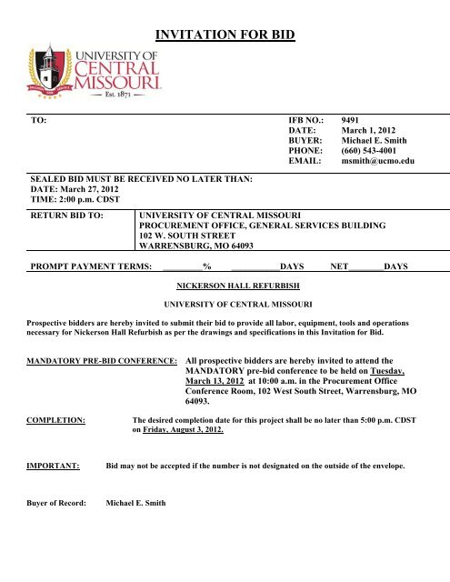
<strong>INVITATION</strong> <strong>FOR</strong> <strong>BID</strong><br />
TO:<br />
IFB NO.:<br />
DATE:<br />
BUYER:<br />
PHONE:<br />
EMAIL:<br />
9491<br />
March 1, 2012<br />
Michael E. Smith<br />
(660) 543-4001<br />
msmith@ucmo.edu<br />
SEALED <strong>BID</strong> MUST BE RECEIVED NO LATER THAN:<br />
DATE: March 27, 2012<br />
TIME: 2:00 p.m. CDST<br />
RETURN <strong>BID</strong> TO:<br />
UNIVERSITY OF CENTRAL MISSOURI<br />
PROCUREMENT OFFICE, GENERAL SERVICES BUILDING<br />
102 W. SOUTH STREET<br />
WARRENSBURG, MO 64093<br />
PROMPT PAYMENT TERMS: _________% ___________DAYS NET________DAYS<br />
NICKERSON HALL REFURBISH<br />
UNIVERSITY OF CENTRAL MISSOURI<br />
Prospective bidders are hereby invited to submit their bid to provide all labor, equipment, tools and operations<br />
necessary for Nickerson Hall Refurbish as per the drawings and specifications in this Invitation for Bid.<br />
MANDATORY PRE-<strong>BID</strong> CONFERENCE: All prospective bidders are hereby invited to attend the<br />
MANDATORY pre-bid conference to be held on Tuesday,<br />
March 13, 2012 at 10:00 a.m. in the Procurement Office<br />
Conference Room, 102 West South Street, Warrensburg, MO<br />
64093.<br />
COMPLETION:<br />
The desired completion date for this project shall be no later than 5:00 p.m. CDST<br />
on Friday, August 3, 2012.<br />
IMPORTANT:<br />
Bid may not be accepted if the number is not designated on the outside <strong>of</strong> the envelope.<br />
Buyer <strong>of</strong> Record:<br />
Michael E. Smith
TABLE OF CONTENTS Page 1<br />
SECTION 00011 – PROJECT MANUAL TABLE OF CONTENTS<br />
INTRODUCTORY IN<strong>FOR</strong>MATION<br />
00001 Project Manual – Table <strong>of</strong> Contents<br />
DIVISION 0 – <strong>BID</strong>DING REQUIREMENTS AND CONTRACT <strong>FOR</strong>MS<br />
000010 Invitation To Bid<br />
000107 Pr<strong>of</strong>essional Certifications<br />
000110 Instruction to Bidders<br />
000111 General Conditions<br />
000112 Construction Schedule – 1 page<br />
000850 Regulation Support Documents<br />
Attachment “A” Proposal Form” - 1 page<br />
Contractors Qualifications – 2 pages<br />
MBE/WBE Compliance Evaluation Form – 1page<br />
MBE/WBE Eligibility Determination Form – 3 pages<br />
MBE/WBE Eligibility Determination Form for Joint Ventures – 4 pages<br />
Application for Waiver – 2pages<br />
Affidavit for Affirmative Action – 1 page<br />
Affidavit <strong>of</strong> Work Authorization - 1 page<br />
Prevailing Wage Rates<br />
DIVISION 1 - GENERAL REQUIREMENTS<br />
011000 SUMMARY<br />
012200 UNIT PRICES<br />
012500 SUBSTITUTION PROCEEDURES<br />
012550 SUBSTITUTION <strong>FOR</strong>M<br />
012600 CONTRACT MODIFICATION PROCEEDURES<br />
013100 PROJECT MANAGEMENT AND COORDINATION<br />
Electronic Data Transfer Agreement<br />
013300 SUBMITTAL PROCEDURES<br />
014000 QUALITY REQUIREMENTS<br />
014200 REFERENCES<br />
015000 TEMPORARY FACILITIES<br />
016000 PRODUCT REQUIREMENTS<br />
017419 CONSTRUCTION WASTE MANAGEMENT AND DISPOSAL<br />
Gould Evans Associates, LC<br />
<strong>University</strong> <strong>of</strong> <strong>Central</strong> <strong>Missouri</strong> – Nickerson Hall Refurbish<br />
Printed Date: 02/28/2012 Project No. 0211-2170
TABLE OF CONTENTS Page 2<br />
DIVISION 2 - SITE CONSTRUCTION<br />
024119 SELECTIVE DEMOLITION<br />
DIVISION 3 – CONCRETE<br />
DIVISION 4 - MASONRY<br />
042200 CONCRETE MASONRY UNITS<br />
DIVISION 5 - METALS<br />
DIVISION 6 - WOOD AND PLASTICS<br />
061053 MISCELLANEOUS ROUGH CARPENTRY<br />
062023 INTERIOR FINISH CARPENTRY<br />
064116 PLASTIC LAMINATE FACED ARCHITECTURAL CABINETS<br />
DIVISION 7 - THERMAL AND MOISTURE PROTECTION<br />
DIVISION 8 - DOORS AND WINDOWS<br />
081213 HOLLOW METAL FRAMES<br />
081416 FLUSH WOOD DOORS<br />
081433 STILE AND RAIL WOOD DOORS<br />
083313 COILING COUNTER DOORS<br />
087100 DOOR HARDWARE<br />
088000 GLAZING<br />
088300 MIRRORS<br />
DIVISION 9 - FINISHES<br />
092216 NON-STRUCTURAL METAL FRAMING<br />
092900 GYPSUM BOARD<br />
093000 TILING<br />
095113 ACOUSTICAL PANEL CEILINGS<br />
096513 RESILIENT WALL BASE AND ACCESSORIES<br />
096519 RESILIENT TILE FLOORING<br />
096813 CARPET TILE<br />
099123 INTERIOR PAINTING<br />
099600 HIGH PER<strong>FOR</strong>MANCE COATINGS<br />
DIVISION 10 – SPECIALTIES<br />
102113 TOILET COMPARTMENTS<br />
102800 TOILET AND BATH ACCESSORIES<br />
DIVISION 11 - EQUIPMENT<br />
113100 RESIDENTIAL APPLIANCES<br />
DIVISION 12 - FURNISHINGS<br />
122113 HORIZONTAL LOUVER BLINDS<br />
123530 RESIDENTIAL CASEWORK<br />
123623 PLASTIC LAMINATE CLAD-COUNTERTOPS<br />
123661 SIMULATED STONE COUNTERTOPS<br />
DIVISION 13 - SPECIAL CONSTRUCTION<br />
DIVISION 14 - CONVEYING SYSTEMS<br />
Gould Evans Associates, LC<br />
<strong>University</strong> <strong>of</strong> <strong>Central</strong> <strong>Missouri</strong> – Nickerson Hall Refurbish<br />
Printed Date: 02/28/2012 Project No. 0211-2170
TABLE OF CONTENTS Page 3<br />
DIVISION 22 – PLUMBING<br />
220010 GENERAL PLUMBING REQUIREMENTS<br />
220500 COMMON WORK RESULTS <strong>FOR</strong> PLUMBING<br />
220515 BASIC PIPING MATERIALS AND METHODS<br />
220523 GENERAL-DUTY VALVES <strong>FOR</strong> PLUMBING PIPING<br />
220529 HANGERS AND SUPPORTS <strong>FOR</strong> PLUMBING PIPING<br />
220553 IDENTIFICATION <strong>FOR</strong> PLUMBING PIPING & EQUIPMENT<br />
220700 PLUMBING INSULATION<br />
221100 WATER DISTRIBUTION PIPING & SPECIALTIES<br />
221111 MECHANICALLY JOINED PLUMBING PIPING SYSTEMS<br />
221300 SANITARY DRAINAGE & VENT PIPING & SPECIALTIES<br />
224000 PLUMBING FIXTURES<br />
DIVISION 23 - MECHANICAL<br />
230010 GENERAL MECHANICAL REQUIREMENTS<br />
230015 ELECTRICAL COORDINATION <strong>FOR</strong> MECHANICAL EQUIPMENT<br />
230500 COMMON WORK RESULTS <strong>FOR</strong> HVAC<br />
230510 BASIC PIPING MATERIALS AND METHODS<br />
230523 GENERAL-DUTY VALVES <strong>FOR</strong> HVAC PIPING<br />
230529 HANGERS AND SUPPORTS <strong>FOR</strong> HVAC PIPING AND EQUIPMENT<br />
230593 TESTING, ADJUSTING, AND BALANCING <strong>FOR</strong> HVAC<br />
230700 HVAC INSULATION<br />
232113 HYDRONIC PIPING<br />
233113 METAL DUCTS<br />
233300 AIR DUCT ACCESSORIES<br />
233416 CENTRIFUGAL HVAC FANS<br />
233713 DIFFUSERS, REGISTERS & GRILLES<br />
238500 ELECTRIC HEATING UNITS<br />
DIVISION 26 – ELECTRICAL<br />
260010 GENERAL ELECTRICAL REQUIREMENTS<br />
260500 COMMON WORK RESULTS <strong>FOR</strong> ELECTRICAL<br />
260502 EQUIPMENT WIRING SYSTEMS<br />
260519 LOW-VOLTAGE ELECTRICAL POWER CONDUCTORS AND CABLES<br />
260526 GROUNDING AND BONDING <strong>FOR</strong> ELECTRICAL SYSTEMS<br />
260529 HANGERS AND SUPPORTS <strong>FOR</strong> ELECTRICAL SYSTEMS<br />
260533 RACEWAY AND BOXES <strong>FOR</strong> ELECTRICAL SYSTEMS<br />
260923 LIGHTING CONTROL DEVICES<br />
262416 PANELBOARDS<br />
262726 WIRING DEVICES<br />
265100 INTERIOR LIGHTING<br />
DIVISION 28 – ELECTRONIC SAFETYAND SECURITY<br />
281111 DIGITAL, ADDRESSABLE FIRE ALARM SYSTEMS<br />
END OF TABLE OF CONTENTS<br />
Gould Evans Associates, LC<br />
<strong>University</strong> <strong>of</strong> <strong>Central</strong> <strong>Missouri</strong> – Nickerson Hall Refurbish<br />
Printed Date: 02/28/2012 Project No. 0211-2170
PROFESSIONAL SEALS / CERTIFICATIONS<br />
ARCHITECTURAL:<br />
I hereby specify that the documents intended to be authenticated by my seal are limited to the<br />
Specification Sections and Drawing Sheets listed below, and I hereby disclaim any responsibility for all<br />
other drawings, specifications, estimates, reports or other documents or instruments relating to or<br />
intended to be used for any part or parts <strong>of</strong> the architectural project unless such documents bear my<br />
signed and dated seal.<br />
Specification Sections<br />
011000 012200 012500 012550 012600 013100<br />
013300 014000 014200 015000 016000 017419<br />
024119 042200 061053 062023 064116 081213<br />
081416 081433 083313 087100 088000 088300<br />
092216 092900 095113 096513 096519 096813<br />
099123 099600 102113 102800 113100 122113<br />
123530 123623 123661<br />
Drawing Sheets<br />
G001 A001 A002 A051 A052 A100<br />
A110 A111 A120 A201 A202<br />
Justin Roth, AIA<br />
Gould Evans Associates, LC<br />
<strong>University</strong> <strong>of</strong> <strong>Central</strong> <strong>Missouri</strong> – Nickerson Hall Refurbish<br />
Printed Date: 02/28/12 Project No. 0211-2170
VOLUME I<br />
TABLE OF CONTENTS<br />
1<br />
GENERAL REQUIREMENTS<br />
PAGE<br />
Instructions to Bidders 3 thru 13<br />
ARTICLE: 1. . . . . . Pre-Bid Conference<br />
2. . . . . . Bidder’s Obligation<br />
3. . . . . . Interpretations/Substitutions<br />
4. . . . . . Bids and Bidding Procedure<br />
5. . . . . . Signing <strong>of</strong> Bids<br />
6. . . . . . Receiving Bids<br />
7. . . . . . Modifications and Withdrawal <strong>of</strong> Bid<br />
8. . . . . . Statement <strong>of</strong> Bidder’s Qualifications<br />
9. . . . . . Award <strong>of</strong> Contract<br />
10. . . . . Contract Security<br />
11. . . . . List <strong>of</strong> Subcontractors<br />
12. . . . . Minority Business Enterprise/Women Business Enterprise (MBE/WBE)<br />
Participation<br />
13. . . . . Exemption <strong>of</strong> <strong>Missouri</strong> Sales/Use Tax<br />
14. . . . . Statutory Preference<br />
General Conditions 14 thru 42<br />
ARTICLE: 1 .......... Definitions<br />
2 .......... Drawings and Specifications<br />
3 .......... Rights and Responsibilities <strong>of</strong> Owner and Designer<br />
4 .......... Inspection <strong>of</strong> Work<br />
5 .......... Compliance with Laws, Permits, Regulations and Inspections<br />
6 .......... Nondiscrimination in Employment<br />
7 .......... Anti-Kickback<br />
8 .......... Patents and Royalties<br />
9 .......... Duties <strong>of</strong> Contractor<br />
10 ........ Bonds<br />
11 ........ Commencement and Completion <strong>of</strong> Work<br />
12 ........ Liquidated Damages/Substantial Completion<br />
13 ........ Progress and Scheduling<br />
14 ........ Superintendence<br />
15 ........ Shop Drawings<br />
16 ........ Samples, Tests and Certificates<br />
17 ........ Materials and Workmanship<br />
18 ........ Insurance<br />
19 ........ Separate Contracts and Cooperation<br />
20 ........ Subcontracts<br />
21 ........ Assignment <strong>of</strong> Contract<br />
22 ........ Indemnification<br />
23 ........ Changes in Work<br />
24 ........ Payment to Contractors<br />
25 ........ Partial Occupancy/Substantial Completion<br />
26 ........ Disputes and Disagreements<br />
27 ........ Termination or Suspension for Cause<br />
28 ........ Record Drawings<br />
29 ........ Warranties<br />
30 ........ Operating Instructions and Service Manuals<br />
31 ........ General Guarantee<br />
32……..MBE/WBE Requirements<br />
33……..Substitution and “Or Approved Equal”<br />
34……...Termination or Suspension for Convenience
The following forms are to be completed and returned with the bidders sealed bid:<br />
2<br />
• Bid Bond in the amount <strong>of</strong> 5%<br />
• Attachment “A” Proposal Form” - 1 page<br />
• Contractors Qualifications – 2 pages<br />
The following forms are to be completed and returned with the bidder’s second submittal (within 24 hours <strong>of</strong> bid<br />
opening):<br />
• MBE/WBE Compliance Evaluation Form – 1page<br />
• MBE/WBE Eligibility Determination Form – 3 pages<br />
• MBE/WBE Eligibility Determination Form for Joint Ventures – 4 pages<br />
• Application for Waiver – 2pages<br />
• Affidavit for Affirmative Action – 1 page<br />
• Affidavit <strong>of</strong> Work Authorization – 1 page<br />
• Pro<strong>of</strong> <strong>of</strong> OSHA 10 Training (each individual worker on the job)<br />
This is a Prevailing Wage Project. (Refer to the attached wage order)<br />
• <strong>Missouri</strong> Division <strong>of</strong> Labor Standards - Annual Wage Order #18 (Johnson County)
PART I<br />
3<br />
1. MANDATORY PRE-<strong>BID</strong> CONFERENCE<br />
INSTRUCTIONS TO <strong>BID</strong>DERS<br />
1.1 All prospective bidders are invited to attend the MANDATORY pre-bid conference to be held on<br />
Tuesday, March 13, 2012 at_10:00 a.m. in the Procurement Office Conference Room, General<br />
Services Buildings, 102 W. South Street, Warrensburg, MO 64093 for the purpose <strong>of</strong> clarifying<br />
any questions or comments pertaining to the plans and specifications.<br />
2. <strong>BID</strong>DERS’ OBLIGATION<br />
2.1 Bidders must carefully examine the entire site <strong>of</strong> the work and shall make all reasonable and<br />
necessary investigations to inform themselves thoroughly as to the facilities available as well as<br />
to all the difficulties involved in the completion <strong>of</strong> all work in accordance with the specifications<br />
and the plans. Bidders are also required to examine all maps, plans and data mentioned in the<br />
specifications. No plea <strong>of</strong> ignorance concerning observable existing conditions or difficulties that<br />
may be encountered in the execution <strong>of</strong> the work under this contract will be accepted as a excuse<br />
for any failure or omission on the part <strong>of</strong> the contractor to fulfill in every detail all <strong>of</strong> the<br />
requirements <strong>of</strong> the contract, nor accepted as a basis for any claims for extra compensation.<br />
2.2 Under no circumstances will a contractor give his plans and specifications to another contractor.<br />
Any bid received from a contractor whose name does not appear on the list <strong>of</strong> bidders having<br />
been mailed and/or paid for the plans and specifications will be subject to rejection.<br />
3. INTERPRETATIONS/SUBSTITUTIONS<br />
3.1 No oral interpretations will be made to any bidder as to the meaning <strong>of</strong> the plans and<br />
specifications or the acceptability <strong>of</strong> alternate products, materials, form or type <strong>of</strong> construction.<br />
Every request for interpretation or substitution shall be made in writing and submitted<br />
with all supporting documents by no later than 2:00 p.m. CDST on Tuesday, March 20,<br />
1012. The request shall be sent directly to the Buyer <strong>of</strong> Record (whose name appears on the first<br />
page <strong>of</strong> this Invitation for Bid), <strong>University</strong> <strong>of</strong> <strong>Central</strong> <strong>Missouri</strong>, Procurement Office,<br />
Warrensburg, MO, 64093 or it may be faxed to the Buyer’s attention at 660-543-8345. Every<br />
interpretation made to a bidder will be in the form <strong>of</strong> an addendum and will be sent as promptly<br />
as practicable to all persons to whom plans and specifications have been issued. All such<br />
addenda shall become part <strong>of</strong> the contract documents.<br />
4. <strong>BID</strong>S AND <strong>BID</strong>DING PROCEDURE<br />
4.1 The bid procedure is a two-step submittal process over a 24 hour period. Bidders shall submit all<br />
first submission forms and accompanying documents by the stated time or their bid will be<br />
rejected for being non-responsive. If the second submission is not received within the 24 hours <strong>of</strong><br />
bid opening, the entire bid will be rejected for being non-responsive. See the list below and the<br />
“Table <strong>of</strong> Contents” for when bid forms are to be submitted.<br />
4.1.1 Depending on the specific project requirements, the following lists <strong>of</strong> bid forms and<br />
times when they are due:
4<br />
4.1.1.1 First Submittal – due before stated date and time <strong>of</strong> bid opening.<br />
4.1.1.1.1 Attachment “A” Bid Form<br />
4.1.1.1.2 Contractor’s Qualifications<br />
4.1.1.1.3 Bid Bond<br />
4.1.1.2 Second Submittal – due within 24 hours <strong>of</strong> stated date and time <strong>of</strong> bid<br />
opening:<br />
4.1.1.2.1 MBE/WBE Compliance Evaluation Form<br />
4.1.1.2.2 MBE/WBE Eligibility Determination Form<br />
4.1.1.2.3 MBE/WBE Eligibility Determination <strong>of</strong> Joint Ventures<br />
4.1.1.2.4 MBE/WBE Application <strong>of</strong> Waiver<br />
4.1.1.2.5 Affidavit <strong>of</strong> Work Authorization<br />
4.1.1.2.6 Affidavit for Affirmative Action<br />
4.1.1.2.7 Pro<strong>of</strong> <strong>of</strong> OSHA 10 Training (each individual worker)<br />
4.1.1.2.8 List <strong>of</strong> Subcontractors<br />
4.1 All bids shall be submitted without modification or reservation on the bid form with each space<br />
properly filled. Bids not on this form will be rejected.<br />
4.2 All bids shall be accompanied by a bid bond, executed by the bidder and a duly authorized surety<br />
company, certified check, cashier’s check or bank draft made payable to <strong>University</strong> <strong>of</strong> <strong>Central</strong><br />
<strong>Missouri</strong>, in the amount <strong>of</strong> five percent (5%) <strong>of</strong> the greatest amount bid including all alternates.<br />
Failure <strong>of</strong> the bidder to submit the full amount required shall be sufficient cause to reject his bid.<br />
The bidder agrees that the proceeds <strong>of</strong> the check, draft or bond shall become the property <strong>of</strong> the<br />
Owner if for any reason the bidder withdraws his bid after closing or if on notification <strong>of</strong> award<br />
refuses or is unable to execute tendered contract, provide an acceptable performance and payment<br />
bond, provide evidence <strong>of</strong> required insurance coverage and provide required copies <strong>of</strong> affirmative<br />
action plans within fourteen (14) consecutive calendar days after such tender.<br />
4.3 The check or draft submitted by the successful bidder will be returned after the receipt <strong>of</strong> an<br />
acceptable performance and payment bond and execution <strong>of</strong> formal contract. Checks or drafts <strong>of</strong><br />
all other bidders will be returned within a reasonable time after it is determined that the bid<br />
represented by same will receive no further consideration by Owner. Bid bonds will only be<br />
returned upon request.<br />
5. SIGNING OF <strong>BID</strong>S
5<br />
5.1 Bids from a partnership shall be signed in the firm name by at least one partner, or in the firm<br />
name by Attorney-in-fact. If signed by Attorney-in-fact there shall be attached to the bid a Power<br />
<strong>of</strong> Attorney evidencing authority to sign the bid, dated and executed by all partners <strong>of</strong> the firm.<br />
5.2 Bids from a corporation shall have the correct corporate name thereon and the signature <strong>of</strong> an<br />
authorized <strong>of</strong>ficer <strong>of</strong> the corporation manually written. Title <strong>of</strong> <strong>of</strong>fice held by the person signing<br />
for the corporation shall appear, along with typed name <strong>of</strong> said individual. Corporate license<br />
number shall be provided and, if a corporation organized in a state other than <strong>Missouri</strong>, a<br />
certificate <strong>of</strong> Authority to do business in the State <strong>of</strong> <strong>Missouri</strong> shall be attached.<br />
5.3 The Contractor understands and agrees that by signing the (IFB/RFP/RFQ or Contract), they<br />
certify the following:<br />
5.3.1 The contractor shall only utilize personnel authorized to work in the United States in<br />
accordance with applicable federal and state laws. This includes but is not limited to the<br />
Illegal Immigration Reform and Immigrant Responsibility Act (IIRIRA) and INA Section<br />
274A.<br />
5.3.2 If the contractor is found to be in violation <strong>of</strong> this requirement or the applicable laws <strong>of</strong><br />
the state, federal and local laws regulations, and if the State <strong>of</strong> <strong>Missouri</strong> has reasonable<br />
cause to believe that the contractor has knowingly employed individuals who are not<br />
eligible to work in the United States, the state shall have the right to cancel the contract<br />
immediately without penalty or recourse and suspend or debar the contractor from doing<br />
business with the state.<br />
5.3.3 The contractor agrees to fully cooperate with any audit or investigation from federal, state<br />
or local law enforcement agencies.<br />
6. RECEIVING <strong>BID</strong>S<br />
6.1 Bids are to be presented in sealed envelopes, which shall be plainly marked with project title, bid<br />
number, bid date and bid time and delivered to the place specified on the first page <strong>of</strong> this<br />
Invitation for Bid. Bidders shall be responsible for actual delivery <strong>of</strong> bids during business hours,<br />
and it shall not be sufficient to show that a bid was dispatched in time to be received before<br />
scheduled closing time for receipt <strong>of</strong> bid.<br />
6.2 Bidders are cautioned to allow ample time for transmittal <strong>of</strong> bids by mail or otherwise. If bid is<br />
mailed, bidder should secure correct information relative to the probable time <strong>of</strong> arrival and<br />
distribution <strong>of</strong> mail at the place where bid is to be received, and make due allowance for possible<br />
delays.<br />
6.3 Bidder’s attention is directed to the fact that no bid will be accepted or considered if delivered<br />
after the specified time for receiving bids.<br />
6.4 No telephonic, telegraphic, electronic mail, facsimile (FAX), or similar bid transmissions will be<br />
accepted or allowed.<br />
6.5 The Owner reserves the right to waive informalities in bids and reject any or all bids.<br />
7. MODIFICATIONS AND WITHDRAWAL OF <strong>BID</strong>
7.1 Bidder may withdraw his bid at any time prior to scheduled closing time for receipt <strong>of</strong> bid, but no<br />
bidder may withdraw his bid after the scheduled closing time for receipt <strong>of</strong> bids.<br />
7.2 Modifications or corrections <strong>of</strong> previously submitted bids may only be submitted by letter or<br />
telegram. Modifications or corrections must be clearly marked with bid date, project name and<br />
bid number and received by the Owner prior to scheduled closing time for receipt <strong>of</strong> bids in<br />
accordance with the following provisions:<br />
7.2.1 To maintain bid confidentiality and insure assignment to the proper bid, any such<br />
written request must be contained in a sealed envelope which is plainly marked<br />
“Modification <strong>of</strong> bid on (project title, bid number and bid date)”.<br />
7.2.2 Telegrams must be received in written form prior to the bid opening time. Since<br />
telegrams cannot be marked as in item 7.2.1, the modification or correction instructions<br />
should be written to protect the confidential nature <strong>of</strong> the bid. For example: “Decrease<br />
Base Bid amount by $5,250", not “Change Base Bid to $104,750". The telegram must<br />
identify the project name and bid number and the bidder.<br />
7.2.3 No request for modifications or correction <strong>of</strong> previously submitted bids will be accepted<br />
by facsimile (FAX) transmission.<br />
8. STATEMENT OF <strong>BID</strong>DER’S QUALIFICATIONS<br />
8.1 Each bidder must submit as part <strong>of</strong> his bid, the Contractor’s Qualifications form which is a part<br />
<strong>of</strong> this Invitation for Bid. The Owner shall have the right to take such steps as it deems<br />
necessary to determine the ability <strong>of</strong> the bidder to perform the work, and the bidder shall furnish<br />
to the Owner such additional information and data for this purpose as he may request. The right<br />
is reserved to reject any bid where an investigation or consideration <strong>of</strong> the information submitted<br />
by such bidder does not satisfy the Owner that the bidder is qualified to carry out properly the<br />
terms <strong>of</strong> the contract documents.<br />
9. AWARD OF CONTRACT<br />
9.1 The Owner reserves the right to reject any and/or all bids and further to waive all informalities in<br />
bidding when deemed in the best interest <strong>of</strong> the Owner.<br />
9.1.1 All awards are contingent upon the availability <strong>of</strong> sufficient funding to complete the<br />
project, and/or Board <strong>of</strong> Governor’s approval.<br />
9.2 The Owner reserves the right to let other contracts in connection with the work, including but<br />
not by way <strong>of</strong> limitation, contracts for the furnishing and installation <strong>of</strong> furniture, equipment,<br />
machines, appliances and other apparatus.<br />
9.3 In awarding the contract the Owner may take into consideration the bidder’s skill, facilities,<br />
capacity, experience, responsibility, previous work record, financial standing, success in<br />
achieving the MBE/WBE participation goal, where applicable; and, the necessity <strong>of</strong> prompt and<br />
efficient completion <strong>of</strong> work herein described. Inability <strong>of</strong> any bidder to meet the requirements<br />
mentioned above may be cause for rejection <strong>of</strong> his bid. However, no contract will be awarded to<br />
6
any individual, partnership or corporation, who has had a contract with the State <strong>of</strong> <strong>Missouri</strong><br />
declared in default within the preceding twelve months.<br />
7<br />
9.4 No bid shall be considered binding upon the Owner until the written contract has been properly<br />
executed, a satisfactory bond has been furnished, evidence <strong>of</strong> required insurance coverage has<br />
been received and appropriate affirmative action plan submitted. Failure to execute and return<br />
the contract and associated documents within the prescribed period <strong>of</strong> time shall be treated, at<br />
the option <strong>of</strong> the Owner, as a breach <strong>of</strong> bidder’s obligation and the Owner shall be under no<br />
further obligation to bidder.<br />
9.5 If the successful bidder is doing business in the State <strong>of</strong> <strong>Missouri</strong> under a fictitious name, he<br />
shall furnish to Owner, attached to the Bid Form, a properly certified copy <strong>of</strong> the certificate <strong>of</strong><br />
Registration <strong>of</strong> Fictitious Name from the State <strong>of</strong> <strong>Missouri</strong>, and such certificate shall remain on<br />
file with the Owner. No contract will be awarded by the Owner until such certificate is<br />
furnished by the bidder.<br />
9.6 Any successful bidder which is a corporation organized in a state other than <strong>Missouri</strong> shall<br />
furnish to the Owner, attached to the Bid Form, a properly certified copy <strong>of</strong> its current<br />
Certificate <strong>of</strong> Authority to do business in the State <strong>of</strong> <strong>Missouri</strong>, such certificate to remain on file<br />
with the Owner. No contract will be awarded by the Owner unless such certificate is furnished<br />
by the bidder.<br />
9.7 Any successful bidder which is a corporation organized in the State <strong>of</strong> <strong>Missouri</strong> shall furnish at<br />
its own cost to the Owner, if requested, a Certificate <strong>of</strong> Good Standing issued by the Secretary <strong>of</strong><br />
State, such certificate to remain on file with the Owner.<br />
9.8 Section 285-230-234 RSMO 1994, transient employers (out-<strong>of</strong>-state employers who temporarily<br />
transact any business in the State <strong>of</strong> <strong>Missouri</strong>) may be required to file a bond with the <strong>Missouri</strong><br />
Department <strong>of</strong> Revenue. No contract will be awarded by the Owner unless the successful bidder<br />
certifies that he/she has complied with all applicable provisions <strong>of</strong> Section 285.230-234.<br />
9.9 RSMo 285.525 and 285.530 require business entities to enroll and participate in a federal work<br />
authorization program in order to be eligible to receive award <strong>of</strong> any state contract in excess <strong>of</strong><br />
$5,000. Bidders should submit with their bid an Affidavit <strong>of</strong> Work Authorization (Section<br />
004541) along with appropriate documentation evidencing such enrollment and participation.<br />
Section-004541, Affidavit <strong>of</strong> Work Authorization is located at,<br />
http://oa.mo.gov/fmdc/dc/contractorforms.htm Information regarding a Memorandum <strong>of</strong><br />
Understanding which is one form <strong>of</strong> appropriate documentation located at https://everify.uscis.gov/enroll/.Submittal<br />
<strong>of</strong> this form and appropriate documentation is required before<br />
the award <strong>of</strong> any contract. In addition the contractor shall be responsible for compliance <strong>of</strong> these<br />
requirements by all subcontractors and suppliers at any tier associated with this contract<br />
10. CONTRACT SECURITY<br />
10.1 The successful bidder shall furnish a performance/payment bond as set forth in General<br />
Conditions Article 10 on a condition prior to the Owner executing the contract and issuing a<br />
notice to proceed.<br />
11. LIST OF SUBCONTRACTORS
8<br />
11.1 Each bidder should submit as part <strong>of</strong> his bid, (or within 24 hours <strong>of</strong> bid opening) a list <strong>of</strong><br />
subcontractors to be used in performing the work. The list must specify the name and address <strong>of</strong><br />
the single designated subcontractor for each category <strong>of</strong> work listed in the Bid Form. If work<br />
within a category will be performed by more than one subcontractor, the bidder must provide the<br />
name and address <strong>of</strong> each subcontractor and specify the exact portion <strong>of</strong> the work to be done by<br />
each. If acceptance/non-acceptance <strong>of</strong> alternates will affect the designation <strong>of</strong> a subcontractor,<br />
the bidder must provide that information for each affected category.<br />
11.2 Failure to list the bidder’s firm, or a subcontractor for each category <strong>of</strong> work identified on the<br />
Bid Form or the listing <strong>of</strong> more than one subcontractor for any category without designating the<br />
portion <strong>of</strong> work to be performed by each may result in rejection <strong>of</strong> the bid. If the bidder intends<br />
to perform any <strong>of</strong> the designated subcontract work with the use <strong>of</strong> his own employees, the bid<br />
shall make the fact clear, by listing his own firm for the subject category.<br />
12. MINORITY BUSINESS ENTERPRISE/WOMEN BUSINESS ENTERPRISE (MBE/WBE)<br />
PARTICIPATION<br />
12.1 For bids in amounts greater than or equal to one hundred thousand dollars ($100,000), the<br />
following provisions shall apply:<br />
12.1.1 MBE/WBE Percentage Goal:<br />
a. The bidder shall have as a goal subcontracting not less than five percent<br />
(5%) <strong>of</strong> the awarded contract price for work to be performed <strong>of</strong><br />
MBE/WBE(s).<br />
12.1.2 Computation <strong>of</strong> MBE/WBE Percent Goal Participation:<br />
a. The total dollar value <strong>of</strong> the work granted to the MBE/WBE by the successful<br />
bidder is counted towards the applicable goal <strong>of</strong> the entire contract.<br />
b. A bidder may count toward his/her MBE/WBE goal only expenditures to<br />
MBE/WBEs that perform a commercially useful function in the work <strong>of</strong> a<br />
contract. A MBE/WBE is considered to perform a commercially useful<br />
function when it is responsible for executing a distinct element <strong>of</strong> the work<br />
contract and carrying out its responsibilities by actually performing, managing<br />
and supervising the work involved. A bidder who is a MBE or WBE may<br />
count 100% <strong>of</strong> the contract amount towards the MBE/WBE goal.<br />
c. A bidder may count toward its MBE/WBE goals expenditures for materials and<br />
supplies obtained from MBE/WBE suppliers and manufacturers, provided that<br />
the MBE/WBE assumes the actual and contractual responsibility for the<br />
provision <strong>of</strong> the materials and supplies.<br />
(1) The bidder may count its entire expenditure to a MBE/WBE<br />
manufacturer. A manufacturer shall be defined as an individual or firm<br />
that produces goods from raw materials or substantially alters them before<br />
resale.
9<br />
(2) The bidder may count sixty percent (60%) <strong>of</strong> its expenditures to<br />
MBE/WBE suppliers that are not manufacturers provided that the<br />
MBE/WBE supplier performs a commercially useful function as defined<br />
above in the supply process.<br />
d. A bidder may count towards his/her MBE/WBE goals that portion<br />
<strong>of</strong> the total dollar value granted to a certified joint venture equal to<br />
the percentage <strong>of</strong> the ownership and control <strong>of</strong> the MBE/WBE<br />
partner in the joint venture.<br />
12.1.3 Certification by bidder <strong>of</strong> MBE/WBE Subcontractors:<br />
a. The bidder shall submit his/her bid the information requested in the<br />
MBE/WBE Compliance Evaluation Form for every MBE/WBE<br />
subcontractor the bidder intends to use on the contract work.<br />
b. If the MBE/WBE subcontractor that the bidder proposed to use on<br />
the project is not certified, the bidder shall submit with his/her bid<br />
the information requested in the MBE/WBE Eligibility<br />
Determination Form. The bidder may determine the status <strong>of</strong><br />
certification by referring to the State <strong>of</strong> <strong>Missouri</strong> Division <strong>of</strong> Design<br />
and Construction's Minority/Women Business Enterprise Directory.<br />
Additional information, clarifications, etc., regarding the listings in<br />
the Directory may be obtained by calling the Buyer <strong>of</strong> Record.<br />
Also, if the proposed subcontractor is certified as a MBE/WBE firm<br />
by the federal government, any other state or government agencies<br />
or any State <strong>of</strong> <strong>Missouri</strong> city or county government agencies, the<br />
bidder shall so note and provide particulars.<br />
c. If the MBE/WBE subcontractor that the bidder intends to use is a<br />
joint venture, and one (1) or more co-venturers is not certified as a<br />
MBE/WBE, the bidder shall submit with his/her bid the information<br />
requested in the MBE/WBE Eligibility Determination Form for<br />
Joint Ventures.<br />
12.1.4 The following information is provided to assist bidders in obtaining<br />
certification <strong>of</strong> subcontractors as MBE/WBE(s).<br />
a. The Commissioner, State <strong>of</strong> <strong>Missouri</strong>, Office <strong>of</strong> Administration,<br />
shall use, but shall not be limited to the following standards in<br />
determining whether a firm is owned and controlled by one (1) or<br />
more minority/woman and is therefore eligible to be certified as a<br />
MBE/WBE.<br />
(1) Bona fide membership in a minority group shall be established<br />
on the basis <strong>of</strong> the individual's claim that he or she is a<br />
member <strong>of</strong> such a minority group and is so regarded by the<br />
particular minority community. However, the Commissioner<br />
is not required to accept this claim if he/she determines the<br />
claim to be invalid.
(2) An eligible MBE/WBE under these regulations shall be an<br />
independent business. The ownership and control by the<br />
minority/woman shall be real, substantial, and continuing and<br />
shall go beyond the pro forma ownership <strong>of</strong> the firm as<br />
reflected in its ownership documents. The minority/woman<br />
shall enjoy the customary incidents <strong>of</strong> ownership and shall<br />
share in the risks and pr<strong>of</strong>its commensurate with ownership<br />
interests, as demonstrated by examination <strong>of</strong> the substance<br />
rather than form <strong>of</strong> the arrangement. Recognition <strong>of</strong> other<br />
business as a separate entity for tax or corporate purposes is<br />
not necessarily sufficient for recognition as a MBE/WBE. In<br />
determining whether a potential MBE/WBE is an independent<br />
business, the Commissioner shall consider all relevant factors,<br />
including the date the business was established, the adequacy<br />
<strong>of</strong> its resources for the work <strong>of</strong> the construction contract, and<br />
the degree to which financial, equipment leasing and other<br />
relationships with non-minority firms vary from industry<br />
practices.<br />
(3) The MBE/WBE owners shall also possess the power to direct<br />
or cause the direction <strong>of</strong> the management and policies <strong>of</strong> the<br />
firm and to make the day-to-day as well as major decisions on<br />
matters <strong>of</strong> management, policy and operation. The firm shall<br />
not be subject to any formal or informal restrictions which<br />
limit the customary discretions <strong>of</strong> the minority/woman<br />
owner(s). There shall be no restriction through, for example,<br />
bylaw provisions, partnership agreements, or charter<br />
requirements for cumulative voting rights or otherwise that<br />
prevent the minority/woman owner(s) from making a business<br />
decision <strong>of</strong> the firm without the cooperation or vote <strong>of</strong> any<br />
owner who is not a minority/woman.<br />
(4) If the owners <strong>of</strong> the firm who are not minorities/women are<br />
disproportionately responsible for the operation <strong>of</strong> the firm,<br />
then the firm is not controlled by minorities/women and shall<br />
not be considered MBE/WBE within the meaning <strong>of</strong> these<br />
regulations. Where the actual management <strong>of</strong> the firm is<br />
contracted out to individuals other than the owner, those<br />
persons who have the ultimate power to hire and fire the<br />
managers can, for the purposes <strong>of</strong> these regulations, be<br />
considered as controlling the business.<br />
(5) All securities which constitute ownership and/or control <strong>of</strong> a<br />
corporation for purposes <strong>of</strong> establishing it as a MBE/WBE<br />
under these regulations shall be held directly by<br />
minorities/women. No securities held in trust, or by any<br />
guardian for a minor, shall be considered as held by<br />
minority/women in determining the ownership or control <strong>of</strong> a<br />
corporation.<br />
10
(6) The contributions <strong>of</strong> capital or expertise by the<br />
minorities/women to acquire their interests in the firm shall be<br />
real and substantial. Examples <strong>of</strong> insufficient contributions<br />
include a promise to contribute capital, a note payable to the<br />
firm or its owners who are not minorities/ women, or the mere<br />
participation as an employee rather than as a manager.<br />
(7) In addition to the standards set out in this section, the<br />
Commissioner shall give special consideration to the following<br />
circumstances in determining eligibility:<br />
a. A joint venture is eligible under these regulations if the<br />
minority/woman partner <strong>of</strong> the joint venture meets the<br />
standards for eligible minorities/women set forth above<br />
and the minority/woman partner is responsible for a<br />
clearly defined portion <strong>of</strong> the work to be performed and<br />
shares in the ownership, control, management<br />
responsibilities, risks and pr<strong>of</strong>its <strong>of</strong> the joint venture.<br />
b. Once certified, a MBE/WBE shall update its<br />
submission annually. Anytime there is a change in<br />
ownership or control <strong>of</strong> the firm, the MBE/WBE shall<br />
update the previously filed information requested in the<br />
MBE/WBE Eligibility Determination Form.<br />
c. Failure <strong>of</strong> a certified MBE/WBE to update or submit<br />
this information shall disqualify the firm or individual<br />
from further participation as a MBE/WBE until such<br />
time that the information is filed by the firm or<br />
individual and approved by the Commissioner.<br />
d. If an appeal has been made and the Commissioner has<br />
denied certification, that decision shall be final for that<br />
contract and other contracts being let by the<br />
Commissioner at the time <strong>of</strong> the denial <strong>of</strong> certification.<br />
MBE/WBE and joint venture denied certification may<br />
correct deficiencies in their ownership and control and<br />
apply for certification only for future contracts.<br />
12.1.5 Waiver <strong>of</strong> MBE/WBE Participation:<br />
a. The bidder is required to make a good faith effort to locate and<br />
contract with MBE/WBEs. If a bidder has made a good faith effort<br />
to secure the required MBE/WBEs and has failed, he/she may submit<br />
with his/her bid the information requested in Application for<br />
MBE/WBE Participation Waiver. The Owner will review the<br />
bidder's actions as set forth in the bidder's Application for Waiver,<br />
and any other factors deemed relevant by the Owner, to determine if<br />
a good faith effort has been made to meet the applicable percentage<br />
11
12<br />
goal. If the bidder is judged not to have made a good faith effort, the<br />
bid shall be rejected.<br />
Bidders who demonstrate that they have made a good faith effort to<br />
include MBE/WBE participation will be awarded the contract<br />
regardless <strong>of</strong> the percent <strong>of</strong> MBE/WBE participation, provided the<br />
bid is otherwise acceptable.<br />
b. In reaching a determination <strong>of</strong> good faith, the Owner may evaluate,<br />
but is not limited to, the following factors:<br />
(1) Attendance at pre-bid meetings to inform bidders and<br />
MBE/WBEs <strong>of</strong> contracting and subcontracting opportunities<br />
and responsibilities associated with MBE/WBE participation;<br />
(2) Attempts by the bidder to advertise in general circulation trade<br />
association and minority focus medial concerning<br />
subcontracting opportunities;<br />
(3) Attempts to provide written notice to specific MBE/WBEs that<br />
their services were being solicited, in sufficient time to allow<br />
for their effective participation;<br />
(4) Follow-up attempts by the bidder to the initial solicitations(s)<br />
to determine with certainty whether MBE/WBEs were<br />
interested.<br />
(5) The extent to which the bidder divided work into projects<br />
suitable for subcontracting to MBE/WBEs;<br />
(6) Whether the bidder provided interested MBE/WBEs with<br />
sufficiently detailed information about the plans, specifications<br />
and requirements about the contract.<br />
(7) Efforts by the bidder to negotiate in good faith with<br />
MBE/WBEs for specific sub-bids. Documentation should<br />
include names, addresses, and telephone numbers <strong>of</strong> firms<br />
contacted, a description <strong>of</strong> all information provided the<br />
MBE/WBEs, and an explanation as to why agreements were<br />
not reached;<br />
(8) Reasons for rejecting MBE/WBE's bid;<br />
(9) The bidder's efforts to locate MBE/WBEs not on the directory<br />
list and assist MBE/WBEs in becoming certified as such;<br />
(10) The bidder's initiatives to encourage and develop MBE/WBEs;
13. EXEMPTION OF MISSOURI SALES/USE TAX<br />
13<br />
(11) The efforts <strong>of</strong> the bidder to help the MBE/WBE overcome any<br />
legal or other barriers impeding the participation <strong>of</strong><br />
MBE/WBEs in the construction contract;<br />
(12) The availability <strong>of</strong> MBE/WBEs and the adequacy <strong>of</strong> the<br />
bidder's efforts to increase the participation <strong>of</strong> such businesses<br />
provided by the persons and organizations consulted by the<br />
bidder.<br />
c. The Owner reserves the right to provide bidders the opportunity to<br />
correct or amplify information concerning MBE/WBE goals.<br />
13.1 This project shall be bid without State sales and/or use tax included in the bid price. The<br />
Owner is a political subdivision <strong>of</strong> the State <strong>of</strong> <strong>Missouri</strong> and is exempt from the sales tax on<br />
purchases paid for out <strong>of</strong> its funds pursuant to Section 144.062 RSMO.<br />
13.2 The Owner will provide a <strong>Missouri</strong> Project Exemption Certificate and a <strong>Missouri</strong> Tax<br />
Exemption Letter to the Contractor who will be purchasing tangible personal property for use in<br />
this project.<br />
13.2.1 The Contractor shall furnish a completed copy <strong>of</strong> the exemption certificate, along with<br />
a copy <strong>of</strong> the <strong>Missouri</strong> Tax Exemption Letter, to all subcontractors, and any<br />
contractors or subcontractors purchasing materials shall present copies <strong>of</strong> such<br />
documents to all material suppliers as authorization to purchase, on behalf <strong>of</strong> the<br />
Owner, all tangible personal property and materials to be incorporated or consumed in<br />
the construction <strong>of</strong> this project and no other on a tax exempt basis. A copy <strong>of</strong> each<br />
certificate must be retained by the purchaser for a period <strong>of</strong> five years.<br />
14. STATUTORY PREFERENCE<br />
14.1 By virtue <strong>of</strong> statutory authority a preference will be given to <strong>Missouri</strong> labor and to products <strong>of</strong><br />
mines, forests and quarries <strong>of</strong> the State <strong>of</strong> <strong>Missouri</strong> when they are found in marketable<br />
quantities in the state, and all such materials shall be <strong>of</strong> the best quality and suitable character<br />
that can be obtained at reasonable market prices, all as provided for in Section 8.280, <strong>Missouri</strong><br />
Revised Statutes 1978 and Cumulative Supplements.<br />
14.2 Furthermore, pursuant to Section 34.076 RSMo 1984 Cumulative Supplements, a preference<br />
shall be given to those persons doing business as <strong>Missouri</strong> firms, corporations, or individuals,<br />
or which maintain <strong>Missouri</strong> <strong>of</strong>fices or places <strong>of</strong> business, when the quality <strong>of</strong> performance<br />
promised is equal or better and the price quoted is the same or less. In addition, in order for a<br />
nondomiciliary bidder to be successful, his bid must be that same percentage lower than a<br />
domiciliary <strong>Missouri</strong> bidder's bid, as would be required for a <strong>Missouri</strong> bidder to successfully<br />
bid in the nondomiciliary's state.<br />
END OF SECTION
PART II<br />
14<br />
GENERAL CONDITIONS<br />
These General Conditions apply to each section <strong>of</strong> these specifications and must be carefully read by each<br />
contractor, as all contractors are subject to the provisions contained herein.<br />
1. DEFINITIONS<br />
1.1 The term "Contract Administrator" shall refer to the Owner's representative at the work site.<br />
1.2 The term "Contractor" shall refer to the person, persons, or company who or which enters<br />
into a contract with the Owner to furnish work under these specifications and drawings.<br />
1.3 The term "Designer" shall refer to the Architect, Engineer or Consultant <strong>of</strong> Record.<br />
1.4 The term "MBE" shall refer to Minority Business Enterprise.<br />
1.5 The term "Minority" shall refer to the following:<br />
1.5.1 "Black Americans," which includes persons having origins in any <strong>of</strong> the black racial<br />
groups <strong>of</strong> Africa.<br />
1.5.2 Hispanic Americans," which includes persons <strong>of</strong> Mexican, Puerto Rican, Cuban,<br />
<strong>Central</strong> or South American or other Spanish culture or origin regardless <strong>of</strong> race.<br />
1.5.3 "Native Americans," which includes persons who are American Indians, Eskimos,<br />
Aleuts or Native Hawaiians.<br />
1.5.4 "Asian-Pacific Americans," which includes persons whose origins are from Japan,<br />
China, Taiwan, Korea, Vietnam, Laos, Cambodia, the Philippines, Samoa, Guam, the<br />
U.S. Trust Territories <strong>of</strong> the Pacific or the Northern Marianas.<br />
1.5.5 "Asian-Indian Americans," which includes persons whose origins are from India,<br />
Pakistan or Bangladesh.<br />
1.6 The term "Minority Business Enterprise" shall refer to a business concern which is at least<br />
fifty-one percent (51%) owned by one (1) or more minority as defined in 1.5 above or in the<br />
case <strong>of</strong> any publicly-owned fifty-one percent (51%) <strong>of</strong> the stock <strong>of</strong> which is owned by one (1)<br />
or more minority as defined in 1.5 above AND whose management and daily business<br />
operations are controlled by one (1) or more minority as defined herein.<br />
1.7 The term "Owner" shall refer to <strong>University</strong> <strong>of</strong> <strong>Central</strong> <strong>Missouri</strong>.<br />
1.8 The term "Subcontractor" shall refer to the person, persons or company who contract under,<br />
or for the performance <strong>of</strong> part or all <strong>of</strong>, the contract between the Owner and Contractor. The<br />
subcontract may or may not be direct with the Contractor.<br />
1.9 The term "WBE" shall refer to Women Business Enterprise.
1.10 The term "Women Business Enterprise" shall refer to a business concern which is at least<br />
fifty-one (51%) owned by one (1) or more women or in the case <strong>of</strong> any publicly-owned<br />
business at least fifty-one percent (51%) <strong>of</strong> the stock <strong>of</strong> which is owned by one (1) or more<br />
women AND whose management and daily business operations are controlled by one (1) or<br />
more women.<br />
1.11 The term "work" shall refer to the labor, material, supplies, plant and equipment required to<br />
perform and complete the service agreed to by the Contractor in safe, expeditious, orderly and<br />
workmanlike manner so that the project shall be complete and finished in the best manner<br />
known to each respective trade.<br />
2. DRAWINGS AND SPECIFICATIONS<br />
2.1 Drawings are intended to show general arrangements, design and extent <strong>of</strong> work and are partly<br />
diagrammatic. As such, they are not intended to be scaled for roughing-in measurements or to<br />
serve as shop drawings.<br />
2.2 Specifications are separated into titled divisions for convenience <strong>of</strong> reference only and to<br />
facilitate letting <strong>of</strong> contracts and subcontracts. The Contractor is responsible for establishing<br />
the scope <strong>of</strong> work for subcontractors, which may cross titled divisions. Neither the Owner or<br />
Designer will establish limits and jurisdiction <strong>of</strong> subcontracts.<br />
2.3 Figured dimensions take precedence over scaled measurements and details over smaller scale<br />
general drawings.<br />
2.4 In case <strong>of</strong> discrepancy between drawings and specifications, specifications shall govern.<br />
Should discrepancies in architectural drawings, structural drawings and mechanical drawings<br />
occur, architectural drawings shall govern and, in case <strong>of</strong> conflict between structural and<br />
mechanical drawings, structural drawings shall govern.<br />
2.5 Anything shown on drawings and not mentioned in these specifications or vice versa, as well as<br />
any incidental work which is obviously necessary to complete the project within the limits<br />
established by the drawings and specifications, although not shown on or described therein,<br />
shall be performed by the Contractor as a part <strong>of</strong> his contract.<br />
2.6 Data concerning lot size, ground elevations, present obstructions on or near the site, locations<br />
and depth <strong>of</strong> sewers, conduits, pipes, wires, etc., position <strong>of</strong> sidewalks, curbs, pavements, etc.,<br />
and nature <strong>of</strong> ground and subsurface conditions have been obtained from sources the Designer<br />
and/or Owner believe reliable, although accuracy <strong>of</strong> such data is not guaranteed.<br />
2.7 Upon encountering conditions differing materially from those indicated in the contract<br />
documents, the Contractor shall promptly notify the Designer and/or Contract Administrator<br />
before such conditions are disturbed. The Designer and/or Contract Administrator shall<br />
promptly investigate said conditions and report to the Owner, with a recommended course <strong>of</strong><br />
action. If conditions do materially differ and cause an increase or decrease in contract cost or<br />
time required for completion <strong>of</strong> any portion <strong>of</strong> the work, a change order will be initiated as<br />
outlined in Article 24 <strong>of</strong> these General Conditions.<br />
15
2.8 Only work included in the contract documents is authorized, and the Contractor shall do no<br />
work other than that described therein or in accordance with appropriately authorized and<br />
approved change orders.<br />
16<br />
3. RIGHTS AND RESPONSIBILITIES OF OWNER AND DESIGNER<br />
3.1 The Owner and/or the Designer acting for the Owner shall give all orders and directions<br />
contemplated under the contract relative to the execution <strong>of</strong> the work. The Owner, normally<br />
represented by the Designer, shall determine the amount, quality, acceptability and fitness <strong>of</strong><br />
kind <strong>of</strong> work and materials which are to be paid for under this contract. In the event any<br />
questions shall arise between the parties hereto, relative to the contract or specifications,<br />
determination or decision <strong>of</strong> the Owner or his representative shall be a condition precedent to<br />
the right <strong>of</strong> the Contractor to receive any money or payment for work under the contract<br />
affected in any manner or to any extent by such question.<br />
3.2 The Owner may file a written notice to the Contractor to dismiss forthwith any <strong>of</strong> his<br />
subcontractors, superintendents, foremen, workmen, watchmen or other employees whom the<br />
Owner may deem incompetent, careless or a hindrance to proper or timely execution <strong>of</strong> the<br />
work, and Contractor shall comply with such notice as promptly as practicable without<br />
detriment to the work or its progress.<br />
3.3 If Contractors refuse to cooperate with the instructions and reasonable requests <strong>of</strong> other<br />
Contractors in the overall coordinating <strong>of</strong> the work, the Owner may take such appropriate<br />
action and issue such instructions as in his judgment may be required to avoid unnecessary and<br />
unwarranted delay.<br />
3.4 If in the judgment <strong>of</strong> the Owner it becomes necessary at any time to accelerate work, the<br />
Contractor, when ordered by the Owner in writing, shall cease work at any point and transfer<br />
his men to such point or points and execute such portions <strong>of</strong> his work as may be required to<br />
enable others to hasten and properly engage and carry out their work, all as directed by the<br />
Owner.<br />
4. INSPECTION OF THE WORK<br />
4.1 The Owner's representative's shall at all times have access to the work whenever it is in<br />
preparation or progress, and Contractors shall provide proper facilities for such access and for<br />
inspection and supervision.<br />
4.2 During progress <strong>of</strong> work the Owner will be represented at the project by the Contract<br />
Administrator and Designer, whose duty it will be to see that the contract is properly fulfilled.<br />
4.3 The Contract Administrator's and Designer's inspections are for the purpose <strong>of</strong> assuring the<br />
Owner that the drawings and specifications are being properly executed. Although the Contract<br />
Administrator and the Designer are instructed to confer with the Contractor regarding<br />
interpretation <strong>of</strong> drawings and specifications, such assistance shall not relieve Contractor <strong>of</strong> any<br />
responsibility for the work.<br />
4.4 The fact that the Contractor Administrator, Designer or Owner has failed to observe faulty<br />
work, or work done which is not in accordance with the drawings and specifications, shall not
elieve the Contractor from responsibility for correcting such work without additional<br />
compensation.<br />
17<br />
4.5 The Owner shall have the right to direct the Contractor to uncover any completed work.<br />
4.5.1 If the Contractor fails to adequately notify the Owner's representatives, as required by<br />
the Contract Documents, the Contractor shall upon written request uncover the work.<br />
The Contractor shall bear all costs associated with uncovering and again covering the<br />
work exposed.<br />
4.5.2 If the Owner's representatives direct work to be uncovered, which was not otherwise<br />
required to be inspected, and the work is found to be defective in any respect, no<br />
compensation shall be allowed for this work. If, however, such work is found to meet<br />
the requirements <strong>of</strong> the contract, the actual cost <strong>of</strong> labor and material necessarily<br />
involved in the examination and replacement plus 10% shall be allowed the<br />
Contractor.<br />
4.6 If the Contractor fails to proceed at once with the correction <strong>of</strong> rejected defective materials or<br />
workmanship, the Owner may by contract or otherwise have the defects remedied or rejected,<br />
materials removed from the site and charge the cost <strong>of</strong> the same against any monies which may<br />
be due the Contractor without prejudice to any other rights or remedies <strong>of</strong> the Owner on the<br />
premises.<br />
4.7 The Contractor must notify the Owner's representative at least two working days before placing<br />
concrete or burying underground utilities, pipelines, etc.<br />
5. COMPLIANCE WITH LAWS, PERMITS, REGULATIONS AND INSPECTIONS<br />
5.1 Since the Owner is the State <strong>of</strong> <strong>Missouri</strong>, municipal or political subdivision ordinances, zoning<br />
ordinances, construction codes and other like ordinances are not applicable to construction on<br />
Owner's property, and Contractor will not be required to submit drawings and specifications to<br />
any municipal or political subdivision authority, obtain construction permits or any other<br />
licenses or permits from or relating to the construction <strong>of</strong> this project. All permits or licenses<br />
required by municipality or political subdivision for operation on property not belonging to<br />
Owner shall be obtained by and paid for by Contractor. Each Contractor shall comply with all<br />
applicable laws, ordinances, rules and regulations as it is not the intent <strong>of</strong> the Owner to<br />
arbitrarily dismiss the authorities identified above.<br />
5.2 The Contractor shall submit to the Owner a list <strong>of</strong> hazardous materials and/or chemicals which<br />
will be brought on the Owner’s property while performing the work associated with this<br />
project. The list must include the following:<br />
a. the name <strong>of</strong> the product<br />
b. the name <strong>of</strong> the manufacturer/distributor<br />
A Materials Safety Data Sheet for each hazardous material/chemical shall be readily available<br />
and submitted to the Owner’s Hazardous Materials Coordinator upon request.<br />
5.2.1 The Contractor shall remove and dispose <strong>of</strong> all hazardous waste generated in<br />
accordance with all Federal and State regulations.
18<br />
6. NONDISCRIMINATION IN EMPLOYMENT<br />
6.1 The Contractor and his subcontractors will not discriminate based on affected group status<br />
unless with respect to sex, age, or handicapped status such restrictions relate to the bona fide<br />
occupational qualifications. Specifically, the Contractor and his subcontractors shall not<br />
discriminate:<br />
6.1.1 Against recipients <strong>of</strong> service on the basis <strong>of</strong> race, color, religion, national origin, sex,<br />
handicap or age.<br />
6.1.2 Against any employee or applicant, for employment on the basis <strong>of</strong> race, color,<br />
religion, national origin, sex or otherwise qualified handicapped status.<br />
6.1.3 Against any applicant for employment or employee on the basis <strong>of</strong> age, where such<br />
applicant or employee is between ages 40 and 70 and where such contractor employs<br />
at least 20 persons.<br />
6.1.4 Against any applicant for employment or employee on the basis <strong>of</strong> that person's status<br />
as a disabled or Vietnam-era veteran.<br />
6.2 The Contractor and subcontractors will take affirmative action to insure applicants are<br />
employed and employees are treated fairly during employment without regard to the above<br />
considerations. Such action shall include, but not be limited to, the following: employment,<br />
upgrading, demotion and transfer; recruitment or recruitment advertising; and selection for<br />
training, including apprenticeship. The Contractor and Subcontractors will give written notice<br />
<strong>of</strong> their commitments under this clause to any labor union with which they have bargaining or<br />
other agreements.<br />
6.3 The Contractor and his subcontractors shall develop, implement, maintain and submit in writing<br />
to the Owner an affirmative action program if at least fifty (50) persons in the aggregate are<br />
employed under this contract. If less than fifty (50) persons in the aggregate are to be<br />
employed under this contract, the Contractor shall submit, in lieu <strong>of</strong> the written affirmative<br />
action program, a properly executed Affidavit for Affirmative Action. The Affidavit for<br />
Affirmative Action will be provided to the Contractor upon award <strong>of</strong> contract. For the purpose<br />
<strong>of</strong> this section, an "affirmative action program" means positive action to influence all<br />
employment practices (including, but not limited to, recruiting, hiring, promoting and training)<br />
in providing equal employment opportunity regardless <strong>of</strong> race, color, sex, national origin,<br />
religion, age (where the person affected is between age 40 and 70), disabled and Vietnam-era<br />
veteran status, and handicapped otherwise qualified status. Such "affirmative action program"<br />
shall include:<br />
6.3.1 A written policy statement committing the total organization to affirmative action and<br />
assigning management responsibilities and procedures for evaluation and<br />
dissemination;<br />
6.3.2 The identification <strong>of</strong> a person designated to handle affirmative action;
19<br />
6.3.3 The establishment <strong>of</strong> non-discriminatory selection standards, objective measures to<br />
analyze recruitment, an upward mobility system, a wage and salary structure, and<br />
standards applicable to lay-<strong>of</strong>f, recall, discharge, demotion and discipline;<br />
6.3.4 The exclusion <strong>of</strong> discrimination from all collective bargaining agreements; and<br />
6.3.5 Performance <strong>of</strong> an internal audit <strong>of</strong> the reporting system to monitor execution and to<br />
provide for future planning.<br />
6.4 In the enforcement <strong>of</strong> this non-discrimination clause, the Owner may use any reasonable<br />
procedures available, including, but not limited to: requests, reports, site visits and inspection<br />
<strong>of</strong> relevant documents <strong>of</strong> contractors and subcontractors.<br />
6.5 In the event <strong>of</strong> the Contractor's or a Subcontractor's noncompliance with any provisions <strong>of</strong> this<br />
section <strong>of</strong> the contract, the Owner may cancel this contract in whole or in part or require the<br />
Contractor to terminate his contract with the subcontractor.<br />
7. ANTI-KICKBACK<br />
7.1 No <strong>of</strong>ficial or employee <strong>of</strong> the Owner or its governing body who is authorized in such capacity<br />
and on behalf <strong>of</strong> the Owner to negotiate, make, accept or approve, or to take part in negotiating,<br />
making, accepting, or approving any architectural, engineering, inspection, construction or<br />
material supply contract or any subcontract in connection with the construction <strong>of</strong> the project,<br />
shall become directly or indirectly interested personally in this contract or in any part here<strong>of</strong>.<br />
No <strong>of</strong>ficer, employee, architect, attorney, engineer or inspector <strong>of</strong> or for the Owner who is<br />
authorized in such capacity and on behalf <strong>of</strong> the Owner to exercise any legislative, executive,<br />
supervisory or other similar functions in connection with the construction <strong>of</strong> the project, shall<br />
become directly or indirectly interested personally in this contract, any material supply contract,<br />
subcontract, insurance contract, or any other contract pertaining to the project.<br />
8. PATENTS AND ROYALTIES<br />
8.1 The Contractor shall hold and save the Owner and its <strong>of</strong>ficers, agents, servants and employees<br />
harmless from liabilities <strong>of</strong> any nature or kind, including cost and expenses, for, or on account<br />
<strong>of</strong>, any patented or unpatented invention, process, article or appliance manufactured or used in<br />
the performance <strong>of</strong> the contract, including its use by the Owner, unless otherwise specifically<br />
stipulated in the contract documents.<br />
8.2 If the Contractor uses any design, device or materials covered by letters, patent or copyright, he<br />
shall provide for such use by suitable agreement with the owner <strong>of</strong> such patented or<br />
copyrighted design, device or material. It is mutually agreed and understood, without<br />
exception, that the contract prices shall include all royalties or costs arising from the use <strong>of</strong><br />
such design, device or materials, in any way involved in the work. The Contractor and/or his<br />
sureties shall indemnify and save harmless the Owner <strong>of</strong> the project from any and all claims for<br />
infringement by reason <strong>of</strong> the use <strong>of</strong> such patented or copyrighted design, device or materials or<br />
any trademark or copyright in connection with work agreed to be performed under this contract<br />
and shall indemnify the Owner for any cost, expense or damage it may be obliged to pay by<br />
reason <strong>of</strong> such infringement at any time during the prosecution <strong>of</strong> the work or after completion<br />
<strong>of</strong> the work.
9. DUTIES OF CONTRACTOR<br />
20<br />
9.1 The Contractor shall supply sufficient labor, material, plant and equipment and pay when<br />
due any laborer, subcontractor or supplier for supplies furnished and otherwise prosecute the<br />
work with diligence to prevent work stoppage and insure completion there<strong>of</strong> within the time<br />
specified. When applicable, the Contractor shall pay not less than the prevailing hourly rate<br />
<strong>of</strong> wages for work <strong>of</strong> a similar character in the locality in which the work is performed, as<br />
determined by the Department <strong>of</strong> Labor and Industrial Relations <strong>of</strong> the State <strong>of</strong> <strong>Missouri</strong> and<br />
as set out in the contract specifications. A copy <strong>of</strong> the wage determination issued for the<br />
project and included as a part <strong>of</strong> the contract documents shall be posted in a prominent and<br />
easily accessible location at the site <strong>of</strong> construction. The Wage Rate notice shall remain<br />
posted during the full time that any workman shall be performing work included in this<br />
construction contract.<br />
9.1.1 The Contractor and each <strong>of</strong> his subcontractors shall submit certified copies <strong>of</strong> their<br />
payroll records concerning work performed under the contract to the Office <strong>of</strong><br />
Purchasing prior to contract acceptance.<br />
9.2 The contractor and each <strong>of</strong> his subcontractors shall forfeit as a penalty to the state,<br />
county, city and county, city, town, district or other political subdivision on whose<br />
behalf the contract is made or awarded ten dollars for each workman employed, for<br />
each calendar day, or portion there<strong>of</strong>, such workman is paid less than the said<br />
stipulated rates for any work done under said contract, by him or by any<br />
subcontractor under him.<br />
9.3 Each Contractor shall be responsible for laying out his own work and for any damage which<br />
may occur to work <strong>of</strong> any other contractor because <strong>of</strong> errors or inaccuracies, as well as be<br />
responsible for unloading, uncrating and handling <strong>of</strong> all materials and equipment to be<br />
erected or placed by him, whether furnished by Contractor or others. Layout <strong>of</strong> mechanical<br />
and electrical work shall be coordinated with layouts <strong>of</strong> Contractor for general construction<br />
work. Unless otherwise directed by the Owner or Designer, salvage materials, waste and<br />
scrap resulting from such work shall be promptly removed from the site by the responsible<br />
Contractor.<br />
9.4 Contractors shall limit operations and storage <strong>of</strong> materials to the area within the project,<br />
except as necessary to connect to existing utilities, and shall not encroach on neighboring<br />
property.<br />
9.4.1 The Contractor shall purchase a Service Vehicle permit for each vehicle that is<br />
parked in a lot requiring a parking permit or if parked at a Service Vehicle parking<br />
space. Permits are purchased at Public Safety located at 306 Broad Street.<br />
9.5 Contractors shall prearrange time with the Contract Administrator in case it becomes<br />
necessary for the interruption <strong>of</strong> any service to make connections, alterations or relocations<br />
and shall fully cooperate with Owner in doing work so as to cause the least annoyance and<br />
interference with the continuous operation <strong>of</strong> the facility. Unless otherwise specified in<br />
these documents, all connections, alterations or relocations as well as all other portions <strong>of</strong><br />
the work will be performed during normal working hours.
21<br />
9.6 Each Contractor shall coordinate all work so there shall be no prolonged interruption <strong>of</strong><br />
existing equipment operation. Any existing plumbing, heating, ventilating, air conditioning<br />
or electrical disconnections necessary which affect portions <strong>of</strong> this construction or building<br />
or any other building must be scheduled with the Contract Administrator to minimize or<br />
avoid any disruption <strong>of</strong> facility operations. In no case, unless previously approved in writing<br />
by the Construction Inspector, shall utilities be left disconnected at the end <strong>of</strong> a work day or<br />
over a weekend. Any interruption <strong>of</strong> utilities either intentionally or accidentally shall not<br />
relieve the Contractor responsible for the interruption from repairing and restoring the utility<br />
to normal service. Repairs and restoration shall be made before the workmen responsible<br />
for the repair and restoration leave the job.<br />
9.7 Each Contractor shall be responsible for repair <strong>of</strong> his damage to property on or <strong>of</strong>f the<br />
project occurring during construction <strong>of</strong> project, and all such repairs shall be made to the<br />
satisfaction <strong>of</strong> the property owner.<br />
9.8 Contractors shall not overload, or permit others to overload, any part <strong>of</strong> any structure during<br />
the performance <strong>of</strong> this contract.<br />
9.9 Each Contractor shall be responsible for shoring required to protect his work or adjacent<br />
property and improvements <strong>of</strong> Owner and shall be responsible for shoring or for giving any<br />
required notice to adjacent property owners and shall pay for any damage caused by failure<br />
to shore or by improper shoring or by failure to give proper notice. Shoring shall be<br />
removed only after completion <strong>of</strong> permanent supports.<br />
9.10 During the performance <strong>of</strong> work the Contractor shall be responsible for providing and<br />
maintaining warning signs, lights, signal devices, barricades, guard rails, fences and other<br />
devices appropriately located on site which will give proper and understandable warning to<br />
all persons <strong>of</strong> danger <strong>of</strong> entry onto land, structure or equipment. Such warning and<br />
protective devices shall be removed only when approved by the Contract Administrator or<br />
Designer.<br />
9.11 The Contractor shall be responsible for protection, including weather protection, and proper<br />
maintenance <strong>of</strong> all equipment and materials installed or to be installed by him.<br />
9.12 The Contractor shall be responsible for care <strong>of</strong> his finished work and shall protect same from<br />
damage or defacement until final acceptance by the Owner. If the work is damaged by any<br />
cause, the Contractor shall immediately begin to make repairs in accordance with the<br />
drawings and specifications. Contractor shall be liable for all damage or loss unless<br />
attributable to the acts or omissions <strong>of</strong> the Owner or Designer. Any claim for<br />
reimbursement shall be submitted in accordance with Article 23.<br />
9.13 The Contractor shall be responsible for initiating, maintaining and supervising all safety<br />
precautions and programs in connection with the performance <strong>of</strong> the Contract.<br />
9.13.1 In the event the Contractor encounters on the site material reasonably believed to<br />
be asbestos or polychlorinated biphenyl (PCB) which has not been rendered<br />
harmless, the Contractor shall immediately stop work in the area affected and<br />
report the condition to the Owner. The work in the affected area shall not<br />
thereafter be resumed except by written agreement <strong>of</strong> the Owner and Contractor if<br />
in fact the material is asbestos or polychlorinated biphenyl (PCB) and has not been
22<br />
rendered harmless. The work in the affected area shall be resumed in the absence<br />
<strong>of</strong> asbestos or polychlorinated biphenyl (PCB), or when it has been rendered<br />
harmless, by written agreement <strong>of</strong> the Owner and Contractor, or in accordance<br />
with final determination by the Designer.<br />
9.13.2 The Contractor shall not be required pursuant to Article 23 to perform, without the<br />
Contractor's consent, any work relating to asbestos or polychlorinated biphenyl<br />
(PCB).<br />
9.13.3 The Contractor shall take reasonable precautions for the safety <strong>of</strong>, and shall<br />
provide reasonable protection to prevent damage, injury or loss to:<br />
9.13.3.1 Employees on the work site and other persons who may be affected<br />
thereby.<br />
9.13.3.2 The work and materials and equipment to be incorporated therein,<br />
whether in storage on or <strong>of</strong>f the site, under care, custody or control<br />
<strong>of</strong> the Contractor or the Contractor's subcontractors or subsubcontractors.<br />
9.13.3.3 Other property at the site or adjacent thereto, such as trees, shrubs,<br />
lawns, walks, pavements, roadways, structures and utilities not<br />
designated for removal, relocation or replacement in the course <strong>of</strong><br />
construction.<br />
9.13.4 The Contractor shall give notices and comply with applicable State and Federal<br />
laws, ordinances, rules, regulations and lawful orders bearing on safety <strong>of</strong> persons or<br />
property or their protection from damage, injury or loss.<br />
9.13.4.1 The Contractor and all Subcontractors shall be responsible for<br />
contacting the Facilities, Planning and Operations Office at (660)<br />
543-4331 and <strong>Missouri</strong> One Call as per RSMO Chapter 319.015-<br />
319.50 <strong>Missouri</strong> State Law Underground Facility and Damage<br />
Prevention.<br />
9.13.4.2 The Contractor shall comply with requirements contained in<br />
RSMO Chapter 292.675 Health and Safety <strong>of</strong> Employees which<br />
requires that any contractor for any public body for the<br />
purposes <strong>of</strong> construction <strong>of</strong> public works and any subcontractor<br />
to such contractor shall provide a ten-hour Occupational Safety<br />
and Health Administration (OSHA) construction safety<br />
program for their on-site employees which includes a course in<br />
construction safety and health approved by OSHA or a similar<br />
program approved by the department which is at least as<br />
stringent as the approved OSHA program, unless such<br />
employees have previously completed the required program.<br />
All employees who have not previously completed the program<br />
are required to complete the program within sixty days <strong>of</strong><br />
beginning work on such construction project.
10. BOND<br />
9.13.5 When use or storage <strong>of</strong> explosives or other hazardous materials or equipment or<br />
unusual methods are approved by the Owner for execution <strong>of</strong> the work, the<br />
Contractor shall exercise utmost care and carry on such activities under supervision<br />
<strong>of</strong> properly qualified personnel.<br />
9.13.6 The Contractor shall designate a responsible member <strong>of</strong> the Contractor's<br />
organization at the site whose duty shall be the prevention <strong>of</strong> accidents. This person<br />
shall be the Contractor's superintendent unless otherwise designated by the<br />
Contractor in writing to the Owner and his representatives.<br />
9.13.7 In an emergency affecting safety <strong>of</strong> persons or property, the Contractor shall act, at<br />
the Contractor's discretion, to prevent threatened damage, injury or loss. Additional<br />
compensation or extension <strong>of</strong> time claimed by the Contractor on account <strong>of</strong> an<br />
emergency shall be determined as provided in Article 23.<br />
9.14 The Contractor, at his own option, may employ a person or persons for watch service at all<br />
times outside <strong>of</strong> regular working hours, and at such times during working hours when work<br />
is not in progress at the building, from the time the excavation work is started until the entire<br />
work is complete. This watchman service will in no way relieve the Contractor <strong>of</strong> his<br />
responsibility for replacing or making good any theft or damage.<br />
9.15 Contractor shall verify all measurements. No extra charges or compensation will be allowed<br />
as a result <strong>of</strong> failure to verify dimensions before ordering materials or fabricating items.<br />
9.16 The Contractor shall provide at the proper time such material as is required for support <strong>of</strong> his<br />
work. If openings or chases are required, whether shown on drawings or not, he shall see<br />
that they are properly constructed by the Contractor or subcontractor whose duty it is to<br />
construct the same.<br />
9.17 All rubbish, debris and dirt resulting from the Contractor's work shall be cleaned up as<br />
required, and removed from the building. The premises shall at all times be kept in a clean,<br />
safe and workmanlike manner.<br />
9.18 The Contractor shall, prior to requesting final inspection, remove manufacturer's advertising<br />
labels from windows, fixtures, equipment and shall leave his work "broom clean" or its<br />
equivalent, unless more exactly specified in the contract documents. Prior to receiving final<br />
payment, the Contractor shall remove all rubbish, tools, scaffold, etc., from the site.<br />
9.19 If any work is required to be specially tested or approved, Contractor shall give the Contract<br />
Administrator and Designer timely notice <strong>of</strong> date for such inspection.<br />
9.20 The Contractor shall attend on-site progress and coordination meetings, at the discretion <strong>of</strong><br />
the Owner, no less than once a month.<br />
9.21 Contractors and/or any subcontractors working under them will incur the total cost <strong>of</strong><br />
replacing lost or stolen keys or the cost <strong>of</strong> re-keying an area or building when it is unable to<br />
surrender <strong>University</strong> keys that have been issued to it through proper <strong>University</strong> procedures.<br />
23
10.1 Contractor shall furnish a performance/payment bond in an amount at least equal to 100% <strong>of</strong><br />
the contract price as security for the faithful performance <strong>of</strong> his contract and for the payment<br />
<strong>of</strong> all persons performing labor on the project and furnishing materials in connection<br />
therewith under this contract. The surety on such bond shall be issued by a surety company<br />
authorized by the <strong>Missouri</strong> Department <strong>of</strong> Insurance to do business in the state <strong>of</strong> <strong>Missouri</strong>.<br />
10.2 All performance/payment bonds furnished in response to this provision shall be provided by<br />
a bonding company with a rating <strong>of</strong> B+ or higher as established by A.M. Best Company, Inc.<br />
in their most recent publication. This requirement may only be waived upon written<br />
approval <strong>of</strong> the Owner.<br />
10.3 Contractor’s bonds shall include such provisions as will guarantee the faithful<br />
performance <strong>of</strong> the prevailing hourly wage clause as provided by this contract.<br />
11. COMMENCEMENT AND COMPLETION OF WORK<br />
11.1 Before a "Notice to Proceed" with the work will be issued, the Contractor must submit to the<br />
Owner the following properly executed instruments:<br />
11.1.1 Contract<br />
11.1.2 Performance/payment bond as described in Article 10.<br />
11.1.3 Certificates <strong>of</strong> Insurance, or the actual policies themselves, showing that the<br />
Contractor has obtained the insurance coverage required by Article 18. If provided,<br />
the certificate <strong>of</strong> insurance shall comply with the requirements <strong>of</strong> Article 18.<br />
11.1.4 Written Affirmative Action Plans as required in Article 6.<br />
11.1.5 List <strong>of</strong> hazardous materials/chemicals as set forth in Article 5.<br />
11.2 These items must be received by the Procurement Office within fourteen (14) consecutive<br />
calendar days after the effective date <strong>of</strong> the contract. If not, the Owner may, at his option,<br />
treat the failure to timely submit them as a refusal by the Contractor to accept a contract for<br />
this work and may retain as liquidated damages the Contractor's bid bond, cashier's check or<br />
certified check as provided in Instructions to Bidders, Article 4.2.<br />
11.3 Within ten (10) days following receipt <strong>of</strong> the "Notice to Proceed," the Contractor shall<br />
submit to the Designer and Contract Administrator for the Owner's approval <strong>of</strong> the<br />
following:<br />
11.3.1 A progress and payment schedule as described in Article 13; and<br />
11.3.2 A complete breakdown <strong>of</strong> the contractor's bid as described in Article 24.<br />
11.4 No payments to the Contractor will be made until the Contractor has submitted these items<br />
and the Owner approves these items as recommended by the Designer and Contract<br />
Administrator; provided, however, that should the Contractor not receive written notification<br />
from the Owner <strong>of</strong> the disapproval <strong>of</strong> any <strong>of</strong> these items within twenty-one (21) calendar<br />
24
days may consider them approved for the purposes <strong>of</strong> the first monthly Application and<br />
Certification for Payment and may proceed accordingly.<br />
25<br />
11.5 Contractor shall commence work upon a date to be specified by the Owner in the "Notice to<br />
Proceed." Contractor shall prosecute the work with faithfulness and energy, and shall<br />
complete the entire work on or before the completion time stated in the contract documents<br />
or pay to the Owner the damages resulting from the failure to timely complete the work as<br />
set out in Article 12.<br />
11.6 Extension <strong>of</strong> time stipulated in the Contract for completion <strong>of</strong> the work will be made when<br />
changes in the work occur, as provided in Article 23, when the work is suspended as<br />
provided in Article 11 (11.8); or when the work <strong>of</strong> the Contractor is delayed on account <strong>of</strong><br />
conditions which could not have been foreseen, or which were beyond the control <strong>of</strong> the<br />
Contractor, his subcontractors or suppliers, and which were not the result <strong>of</strong> their fault or<br />
negligence. Extension <strong>of</strong> time for completion shall also be allowed for any delays in the<br />
progress <strong>of</strong> the work caused by any act (except as provided elsewhere in these General<br />
Conditions) or neglect <strong>of</strong> the Owner or his employees or by other Contractors employed by<br />
the Owner, or for any delay in the furnishing <strong>of</strong> drawings and necessary information by the<br />
Designer, or delay in return <strong>of</strong> shop drawings, or for any other cause which in the opinion <strong>of</strong><br />
the Owner entitles the Contractor to an extension <strong>of</strong> time, including but not restricted to<br />
fires, floods, unusually severe weather, or labor strikes.<br />
11.7 The Contractor shall notify the Owner promptly <strong>of</strong> any occurrence or conditions which in<br />
the Contractor's opinion entitle him to an extension <strong>of</strong> time. The notice shall be in writing<br />
and shall include all necessary supporting materials with details <strong>of</strong> any resultant costs and be<br />
submitted in ample time to permit full investigation and evaluation <strong>of</strong> the Contractor's claim.<br />
The Owner shall promptly acknowledge the Contractor's notice and, after recommendation<br />
from the Contract Administrator and/or Designer, shall provide a decision to the Contractor.<br />
Failure on the part <strong>of</strong> the Contractor to provide such notice and to detail the costs shall<br />
constitute a waiver by the Contractor <strong>of</strong> any claim.<br />
11.8 When conditions at the site <strong>of</strong> the proposed work are considered by the Owner to be<br />
unsatisfactory for prosecution <strong>of</strong> the work, Contractor may be ordered in writing to suspend<br />
the work or any part there<strong>of</strong> until reasonable conditions exist. When such suspension is not<br />
due to fault or negligence <strong>of</strong> the Contractor, time allowed for completion <strong>of</strong> such suspended<br />
work will be extended by a period <strong>of</strong> time equal to that lost due to delay occasioned by<br />
ordered suspension.<br />
12. LIQUIDATED DAMAGES/SUBSTANTIAL COMPLETION<br />
12.1 DELETED<br />
13. PROGRESS AND SCHEDULING<br />
13.1 Each Contractor shall submit for the Owner's approval, in reproducible form, a progress<br />
schedule showing the rate <strong>of</strong> progress he agrees to maintain and the order in which he<br />
proposed to carry on various phases <strong>of</strong> work. Schedule shall show percentage <strong>of</strong> work<br />
completed at any time, anticipated monthly payments by Owner, as well as significant dates<br />
(such as completion <strong>of</strong> excavation, concrete foundation work, underground lines,<br />
superstructure, roughing-in, enclosure, hanging <strong>of</strong> fixtures, etc.) which shall serve as check
points to determine compliance with approved schedule. Progress schedule <strong>of</strong> the<br />
Contractor shall be submitted to subcontractors to permit coordinating their progress<br />
schedules to the general construction work.<br />
26<br />
13.2 Values employed in preparation <strong>of</strong> any schedules will be used only for determining the basis<br />
for partial payments and will not be considered as a basis for additions to or deductions from<br />
the contract price.<br />
13.3 There will be no payments until the progress schedule has been approved by the Owner, and<br />
subsequent payments will be suspended if the project schedule has not been adequately<br />
updated to reflect actual conditions.<br />
13.4 Contractor shall employ and supply a sufficient force <strong>of</strong> workmen, material, and equipment<br />
and shall pay when due, any workman, subcontractor or supplier and otherwise prosecute<br />
the work with such diligence so as to maintain the rate <strong>of</strong> progress indicated on the progress<br />
schedule, prevent work stoppage, and insure completion <strong>of</strong> the project within the time<br />
specified.<br />
14. SUPERINTENDENCE<br />
14.1 The Contractor shall keep on site, during progress <strong>of</strong> the work, a competent superintendent<br />
satisfactory to the Owner. The superintendent shall represent the Contractor in his absence<br />
and all directions given to him shall be as binding as if given to the Contractor. He shall<br />
carefully study and compare all drawings, specifications and other instruction and shall, at<br />
once, report to the Owner and his representatives any error, inconsistency or omission which<br />
he may discover. The superintendent shall not be changed except with the consent <strong>of</strong> the<br />
Owner.<br />
15. SHOP DRAWINGS<br />
15.1 The Contractor shall submit, with such promptness as to cause no delay in his work or in<br />
that <strong>of</strong> any other contractors, all shop and setting drawings. Such drawings shall be<br />
submitted to the Owner in four (4) copies for the Owner's use and additional copies as<br />
required for the Contractors, subcontractors, material suppliers, and to meet the requirements<br />
for maintenance manuals, etc., as described in Article 30.<br />
15.2 Each drawing and/or series <strong>of</strong> drawings submitted must be accompanied by a letter <strong>of</strong><br />
transmittal giving a list <strong>of</strong> the titles and numbers <strong>of</strong> the drawings. Each series shall be<br />
numbered consecutively for ready reference and each drawing shall be marked with the<br />
following information.<br />
15.2.1 Date <strong>of</strong> Submission<br />
15.2.2 Name <strong>of</strong> Project<br />
15.2.3 Location<br />
15.2.4 Division <strong>of</strong> Work<br />
15.2.5 Name <strong>of</strong> Submitting Contractor
27<br />
15.2.6 Name <strong>of</strong> Subcontractor<br />
15.2.7 Identify as either a base bid item or an alternate number.<br />
15.3 All subcontractors' shop drawings and schedules shall be submitted by the Contractor and<br />
shall bear the stamp <strong>of</strong> the Contractor as evidence that he has received and approved them.<br />
Any shop drawings and schedules submitted without this stamp will be returned to him for<br />
resubmission and the drawings and schedules will be considered as never having been<br />
submitted.<br />
15.4 The Contractor shall include with the shop drawing a letter indicating all deviations from the<br />
drawings and/or specifications. Failure to so notify <strong>of</strong> such deviations will be grounds for<br />
subsequent rejection <strong>of</strong> the related work or materials. If, in the opinion <strong>of</strong> the Designer, the<br />
deviations are not acceptable, the Contractor will be required to furnish the item as specified<br />
and indicated on the drawings.<br />
15.5 It is the Contractor's obligation and responsibility to check all <strong>of</strong> his shop drawings and<br />
schedules to be fully responsible for them and for their coordination with connecting work.<br />
Shop drawings and schedules shall indicate in detail all parts <strong>of</strong> an item <strong>of</strong> work, including<br />
erection and setting instructions and engagements with the work <strong>of</strong> other trades.<br />
15.6 The Designer shall check shop drawings and schedules with reasonable promptness and<br />
approve them only if they conform to the design concept <strong>of</strong> the project and compliance with<br />
the information given in the contract documents. The approval shall not relieve the<br />
Contractor from the responsibility for deviations from the drawings and specifications,<br />
unless he has called the Designer's attention to the deviation, in writing, at the time <strong>of</strong><br />
submission. An approval <strong>of</strong> any such modification will be given only if it is in the interest<br />
<strong>of</strong> the Owner, to affect an improvement in the work, does not increase the contract sum<br />
and/or completion time, is subject generally to all contract stipulations and covenants, and is<br />
without prejudice to any and all rights under the surety bond.<br />
15.7 No extension <strong>of</strong> time will be granted the Contractor because <strong>of</strong> his failure to submit shop<br />
drawings and schedules in ample time to allow for review, possible resubmittals and<br />
approval. Fabrication <strong>of</strong> work shall not commence until the Contractor has received<br />
approval. He shall furnish prints <strong>of</strong> his approved shop drawings and schedules to all<br />
contractors whose work is in any way related to the work under the contract. Only prints<br />
bearing this approval will be allowed on the site <strong>of</strong> construction.<br />
15.8 On completion <strong>of</strong> the work, and as a condition precedent to receiving final payment, all shop<br />
drawings and schedules <strong>of</strong> all work for all trades shall be corrected to a true and actual<br />
representation <strong>of</strong> the work actually performed, erected and installed. Drawings showing the<br />
actual installation <strong>of</strong> all underground services, utilities and structures <strong>of</strong> every description<br />
shall be furnished the Contract Administrator upon completion <strong>of</strong> the work as set out in<br />
Article 28.<br />
16. SAMPLES, TESTS AND CERTIFICATES<br />
16.1 The Contractor shall prepare samples <strong>of</strong> all items requested or required by the specification.<br />
Samples shall be properly identified and submitted with such promptness as to cause no
delay in his work or in that <strong>of</strong> any other Contractor and to allow for consideration by the<br />
Owner and Designer.<br />
28<br />
16.2 Each set <strong>of</strong> samples submitted must be accompanied by a letter <strong>of</strong> transmittal containing the<br />
following information:<br />
16.2.1 Date <strong>of</strong> Submission<br />
16.2.2 Name <strong>of</strong> Project<br />
16.2.3 Location<br />
16.2.4 Section Number <strong>of</strong> Specification<br />
16.2.5 Name <strong>of</strong> Submitting Contractor<br />
16.2.6 Name <strong>of</strong> Subcontractor<br />
16.3 No materials shall be delivered to the site <strong>of</strong> construction or incorporated into the work until<br />
the Contractor has received approval. Any materials installed prior to receipt <strong>of</strong> such<br />
approval shall be subject to rejection by the Owner or his representative.<br />
16.4 Samples shall be labeled to designate material or product represented, grade, place <strong>of</strong> origin,<br />
name <strong>of</strong> producer and name <strong>of</strong> Contractor.<br />
16.5 Approval <strong>of</strong> material is general and shall not constitute waiver <strong>of</strong> Owner's right to demand<br />
full compliance with contract requirements.<br />
16.6 Rejected samples will be destroyed unless the Contractor authorizes the Designer at the time<br />
<strong>of</strong> submittal, to return samples at the Contractor's expense.<br />
16.7 After delivery <strong>of</strong> materials the Designer may, with concurrence <strong>of</strong> the Owner, make such<br />
tests as he deems necessary. The Contractor shall furnish test samples at no cost to the<br />
Owner. If the material, equipment or accessory fails to meet the contract requirements, all<br />
costs <strong>of</strong> testing shall be paid by the Contractor. If the item meets the contract requirements,<br />
costs <strong>of</strong> testing will be paid by Owner.<br />
16.8 On the basis <strong>of</strong> test results, materials, workmanship, equipment or accessories may be<br />
rejected even though general approval has been given. If the rejected items have been<br />
incorporated in work, the Owner or his representative may require the Contractor to remove<br />
and replace the item with one meeting contract requirements or to demand and secure such<br />
reparation to the Owner from the Contractor as is equitable.<br />
16.9 The Owner reserves the right to require Contractor to furnish a certificate guaranteeing that<br />
material or equipment as submitted complies with contract requirements. Certificates shall<br />
be in notarized affidavit form. If statement originates with manufacturer, Contractor shall<br />
endorse all claims and submit the statement in his own name.<br />
16.10 When directed by the Owner's representative, and unless otherwise required within the<br />
technical specification, samples <strong>of</strong> finished masonry and field applied paints and finishes
shall be located as directed and shall include sample panels constructed at site size as<br />
required.<br />
29<br />
16.11 All tests required by the specifications shall be paid for by the Contractor and performed by<br />
testing laboratories approved by the Owner.<br />
17. MATERIALS AND WORKMANSHIP<br />
17.1 Unless otherwise specified, all materials shall be new and both workmanship and materials<br />
shall be <strong>of</strong> the best quality. If required by the Owner, satisfactory evidence shall be<br />
furnished as to the kind and quality <strong>of</strong> the materials and workmanship.<br />
17.2 All materials and workmanship used in the work shall be subject to the inspection <strong>of</strong> the<br />
Designer and Contract Administrator, and any work which is deemed defective shall be<br />
removed, rebuilt or made good. The cost <strong>of</strong> such correction shall be borne by the<br />
Contractor. All condemned materials shall be immediately removed from the site <strong>of</strong> the<br />
work.<br />
17.3 Failure or neglect on the part <strong>of</strong> the Owner to condemn or reject bad or inferior materials or<br />
workmanship shall not be construed to imply an acceptance <strong>of</strong> any work. The work herein<br />
specified to be done is not to be considered as finally accepted until it is so stated in writing<br />
by the Owner.<br />
17.4 Unless otherwise provided and stipulated within these specifications, the Contractor shall<br />
furnish, construct, and/or install and pay for materials, devices, mechanisms, equipment, all<br />
necessary personnel, utilities including, but not limited to water, heat, light and electric<br />
power, transportation services, applicable taxes <strong>of</strong> every nature, and all other facilities<br />
necessary for the proper execution and completion <strong>of</strong> the work.<br />
17.5 All temporary shoring, bracing, etc., required for the removal <strong>of</strong> existing work and/or for the<br />
installation <strong>of</strong> new work shall be included in this contract. This must be done to the entire<br />
satisfaction <strong>of</strong> the Owner but the Contractor must assume full responsibility for the work.<br />
The Contractor shall make good, at no cost to the Owner, any damage caused by improper<br />
support or failure <strong>of</strong> shoring in any respect.<br />
17.6 Contractor shall, at all times, enforce strict discipline and good order among his employees,<br />
and shall not employ on the work any unfit person or anyone not skilled in the work<br />
assigned to him.<br />
17.7 Contractor shall carefully examine the plans and drawings and shall be responsible for the<br />
proper fitting <strong>of</strong> his material, equipment and apparatus into the building.<br />
17.8 Contractor shall base his bid only on materials, method <strong>of</strong> construction and equipment as<br />
indicated.<br />
17.9 Contractor shall promptly remove at his own expense all rejected materials from site <strong>of</strong><br />
work.<br />
17.10 When a material has been approved, no change in brand or make will be permitted unless:
18. INSURANCE<br />
17.10.1 Written verification is received from the manufacturer stating they cannot make<br />
delivery on the date previously agreed, or<br />
17.10.2 Material delivered fails to comply with contract requirements.<br />
18.1 The Contractor shall procure and maintain for the duration <strong>of</strong> the contract issued a policy or<br />
policies <strong>of</strong> insurance for the protection both the Contractor and the Owner and their<br />
respective <strong>of</strong>ficers, <strong>of</strong>ficials, agents, consultants and employees. The Owner requires<br />
certification <strong>of</strong> insurance coverage from the Contractor prior to commencing work.<br />
18.2 Contractor shall provide and maintain during the life <strong>of</strong> the contract and until final<br />
acceptance <strong>of</strong> the work, insurance acceptable to the Owner which will afford protection and<br />
coverage in accordance with the requirements set forth below.<br />
18.2.1 Workmen's Compensation Insurance: Workmen's Compensation Insurance for all<br />
<strong>of</strong> his employees at the site <strong>of</strong> the project, and, in case any work is sublet,<br />
Contractor shall require any and/or all subcontractor(s) similarly to provide<br />
Workmen's Compensation Insurance for all his employees unless such employees<br />
are covered by the protection afforded by Contractor. In case any class <strong>of</strong><br />
employees engaged in hazardous work under this contract at the site <strong>of</strong> the project<br />
is not covered under the Workmen's Compensation Statute, the Contractor shall<br />
provide and shall cause each subcontractor to provide Employer's Liability<br />
Insurance. Contractors shall provide coverage under the "Occupational Disease<br />
Act" <strong>of</strong> the State <strong>of</strong> <strong>Missouri</strong>, in addition to the above requirements, if the<br />
operations <strong>of</strong> the Contractor or any subcontractor are applicable thereunder.<br />
Workmen's Compensation Insurance shall comply in all respects with the<br />
requirements <strong>of</strong> the Statutes <strong>of</strong> the State <strong>of</strong> <strong>Missouri</strong>.<br />
18.2.2 Public Liability and Property Damage Insurance: Public Liability and Property<br />
Damage Insurance in comprehensive general liability form as shall protect<br />
Contractor and any subcontractor performing work covered by this contract from<br />
claims for damages for personal injury, including wrongful death, and from claims<br />
for property damage which may arise from the operations under the contract<br />
including all trucks and automobiles used, whether owned or not, and whether such<br />
operations be by the Contractor or any subcontractor or by anyone directly<br />
employed by either <strong>of</strong> them. The amount <strong>of</strong> insurance shall not be less than the<br />
following:<br />
1. Public Liability and Property Damage -<br />
Bodily injury:<br />
each person $300,000<br />
aggregate $2,000,000<br />
Property damage:<br />
each accident $2,000,000<br />
aggregate $2,000,000<br />
30
2. Automobile Public Liability and Property Damage -<br />
31<br />
Bodily injury:<br />
each person $300,000<br />
aggregate $2,000,000<br />
Property damage:<br />
each accident $1,000,000<br />
Such policy or policies shall by proper endorsement cover any liability <strong>of</strong><br />
Contractor under the indemnification provision, Article 22 <strong>of</strong> these General<br />
Conditions.<br />
18.2.3 Insurance Covering Special Hazards: The Public Liability and Property Damage<br />
Insurance policy or policies <strong>of</strong> the Contractor shall provide coverage for special<br />
hazards such as operation <strong>of</strong> material hoists, blasting or other use <strong>of</strong> explosives,<br />
and damage to underground property.<br />
18.2.4 Owner's Protective Liability Insurance: Owner's Protective Liability Insurance for<br />
protection <strong>of</strong> the Owner and the Designer protecting them against the standard<br />
hazards, except liability from operation <strong>of</strong> trucks and automobiles, and with the<br />
amount <strong>of</strong> coverage provided in the Public Liability and Property Damage<br />
Insurance <strong>of</strong> Contractor.<br />
18.2.5 Builder's Risk or Installation Floater Insurance: Insurance upon the work and all<br />
materials, equipment, supplies, temporary structures and similar items which may<br />
be incident to the performance <strong>of</strong> the work and located at or adjacent to the site,<br />
against loss or damage from fire and such other casualties as are included in<br />
extended coverage in broad “All Risk” form, including coverage for Flood and<br />
Earthquake, in an amount not less than the replacement cost <strong>of</strong> the work or the<br />
contract price, whichever is greater, with loss payable to Contractor and Owner as<br />
their respective interest may appear. Contractor shall maintain sufficient insurance<br />
to cover the full value <strong>of</strong> the work and materials as the work progresses, and shall<br />
furnish Owner copies <strong>of</strong> all endorsements. If Builder’s Risk Reporting-Form <strong>of</strong><br />
Endorsement is used, Contractor shall make all reports as required therein so as to<br />
keep in force an amount <strong>of</strong> insurance which will equal the replacement cost <strong>of</strong> the<br />
work, materials, equipment, supplies, temporary structures, and other property<br />
covered thereby; and if, as a result <strong>of</strong> Contractor’s failure to make any such report,<br />
the amount <strong>of</strong> insurance so recoverable shall be less than such replacement cost,<br />
Contractor’s interest in the proceeds <strong>of</strong> such insurance, if any, shall be subordinated<br />
to Owner’s interest to the end that Owner may receive full reimbursement for its<br />
loss.<br />
18.3 All insurance shall be procured through agencies and be written by insurance companies<br />
which are acceptable to and approved by the Owner and shall be obtained and paid for by<br />
Contractor.<br />
18.4 Within fourteen (14) consecutive calendar days after receipt <strong>of</strong> the purchase order directing<br />
him to do so, the Contractor shall furnish the Office <strong>of</strong> Purchasing with certificates showing
32<br />
that the Owner is covered by the required insurance and showing the type, amount, class <strong>of</strong><br />
operations covered, effective dates and dates <strong>of</strong> expiration <strong>of</strong> the policies.<br />
18.5 Upon receipt <strong>of</strong> any notice <strong>of</strong> cancellation or alteration, Contractor shall within five (5) days<br />
procure other policies <strong>of</strong> insurance similar in all respects to the policy or policies about to be<br />
canceled or altered. Neither the Contractor nor the Contractor's agents shall perform work<br />
on the Owner's property without the minimum insurance set forth herein being fully in force.<br />
There shall be no time extension granted for the Contractor's failure to maintain required<br />
insurance coverage.<br />
19. SEPARATE CONTRACTS AND COOPERATION<br />
19.1 The Owner reserves the right to let other contracts in connection with this work. The<br />
Contractor shall afford other contractors reasonable opportunity for the introduction and<br />
storage <strong>of</strong> their materials and the execution <strong>of</strong> their work and shall properly connect and<br />
coordinate his work with theirs.<br />
19.2 The Contractor shall consult the drawings for all other contractors in connection with this<br />
work. Any work conflicting with the above shall be brought to the attention <strong>of</strong> the Owner<br />
before the work is performed. If the Contractor fails to do this, and constructs any work<br />
which interferes with the work <strong>of</strong> another contractor, he shall remove any part so conflicting<br />
and rebuild same, as directed by the Owner at no additional cost to the Owner.<br />
19.3 Each Contractor shall be required to coordinate his work with other Contractors so as to<br />
afford others reasonable opportunity for execution <strong>of</strong> their work. No Contractor shall delay<br />
any other Contractor by neglecting to perform his work at the proper time. If any Contractor<br />
causes delay to another, he shall be liable directly to that Contractor for such delay in<br />
addition to any liquidated damages which might be due the Owner.<br />
19.4 Each Contractor shall be responsible for damage done to Owner's or other Contractor's<br />
property by him or his employees through his or their fault or negligence.<br />
19.5 Should a contractor sustain any damage through any act or omission <strong>of</strong> any other contractor<br />
having a contract with the Owner, the Contractor so damaged shall have no claim or cause<br />
<strong>of</strong> action against the Owner for such damage, but shall have a claim or cause <strong>of</strong> action<br />
against the other Contractor to recover any and all damages sustained by reason <strong>of</strong> the acts<br />
or omissions <strong>of</strong> such contractor. The phrase "acts or omissions" as used in this section shall<br />
be defined to include, but not be limited to, any unreasonable delay on the part <strong>of</strong> any such<br />
contractors.<br />
20. SUBCONTRACTS<br />
20.1 Subcontractor assignments as identified by the Contractor shall not be changed without<br />
written approval <strong>of</strong> the Owner. The Owner will not approve changes <strong>of</strong> a listed<br />
Subcontractor unless the Subcontractor cannot or will not perform the work as specified.<br />
20.2 Contractor agrees that he is as fully responsible to the Owner for the acts and omissions <strong>of</strong><br />
his subcontractors and <strong>of</strong> persons either directly or indirectly employed by them as he is for<br />
the acts and omissions <strong>of</strong> persons directly employed by him.
33<br />
20.3 Every subcontractor shall be bound by the applicable terms and provisions <strong>of</strong> the contract<br />
documents, but no contractual relationship shall exist between any subcontractor and the<br />
Owner unless the right <strong>of</strong> the Contractor to proceed with the work is suspended or the<br />
contract is terminated as herein provided, and the Owner in writing elects to assume the<br />
subcontract.<br />
21. ASSIGNMENT OF CONTRACT<br />
21.1 No assignment by Contractor <strong>of</strong> any amount or any part <strong>of</strong> the contract or <strong>of</strong> the funds to be<br />
received thereunder will be recognized unless such assignment has had the written approval<br />
<strong>of</strong> the Owner and the surety has been given due notice <strong>of</strong> such assignment and has furnished<br />
written consent thereto. In addition to the usual recitals in assignment contracts, the<br />
following language must be set forth: "It is agreed that the funds to be paid to the assignee<br />
under this assignment are subject to performance by the Contractor <strong>of</strong> the contract and to<br />
claims or liens for services rendered or materials supplied for the performance <strong>of</strong> the work<br />
called for in said contract in favor <strong>of</strong> all persons, firms or corporations rendering such<br />
services or supplying such materials."<br />
22. INDEMNIFICATION<br />
22.1 Contractor agrees to indemnify and save harmless Owner and Designer, their agents,<br />
servants and employees, from and against any and all liability for damage arising from<br />
injuries to persons or damage to property occasioned by any acts or omissions <strong>of</strong> Contractor,<br />
any subcontractors, agents, servants or employees, including any and all expense, legal or<br />
otherwise, which may be incurred by Owner or Designer, its agents, servants or employees,<br />
in defense <strong>of</strong> any claim, action or suit, irrespective <strong>of</strong> any claims that an act, omission or<br />
negligence <strong>of</strong> Owner or Designer, its agents, servants or employees contributed to such<br />
injury or damage.<br />
22.2 The obligations <strong>of</strong> the Contractor under this paragraph shall not extend to the liability <strong>of</strong> the<br />
Designer, his agents or employees, arising out <strong>of</strong> (1) the preparation or approval <strong>of</strong> maps,<br />
drawings, opinions, reports, surveys, change orders, design or specifications, or (2) giving <strong>of</strong><br />
or the failure to give directions or instructions by the Designer, his agents or employees as<br />
required by the contract documents provided such giving or failure to give is the primary<br />
cause <strong>of</strong> the injury or damage.<br />
23. CHANGES IN THE WORK<br />
23.1 The Owner and no other, without giving notice to the surety and without invalidating the<br />
contract, may order extra work or make changes by altering, adding to or deducting from the<br />
work, the contract sum being adjusted accordingly. All such work shall be executed under<br />
the conditions <strong>of</strong> the original contract except that any claim for extension <strong>of</strong> time caused<br />
thereby shall be adjusted at the time <strong>of</strong> ordering such change.<br />
23.2 The amount <strong>of</strong> any adjustment in the contract price for authorized changes or the use <strong>of</strong><br />
contract allowances shall be agreed upon before such changes or authorizations become<br />
effective and shall be determined, through submission <strong>of</strong> a request for bid prepared by the<br />
Designer, as follows:
34<br />
23.2.1 By an acceptable unit price or lump sum bid from Contractor and subcontractor.<br />
Bid shall include all take<strong>of</strong>f sheets <strong>of</strong> each Contractor and subcontractor.<br />
Breakdown shall include a listing <strong>of</strong> each item <strong>of</strong> material with unit prices and<br />
number <strong>of</strong> hours <strong>of</strong> labor for each task. Labor costs per hour shall be included<br />
with labor burden identified, which shall be not less than the prevailing wage rate,<br />
etc. Overhead and pr<strong>of</strong>it shall be shown separately for each subcontractor and the<br />
Contractor.<br />
23.2.2 By a cost-plus-fixed fee (percentage) basis with maximum price, total cost not to<br />
exceed said maximum. Breakdown shall include a listing <strong>of</strong> each item <strong>of</strong> material<br />
with unit prices and number <strong>of</strong> hours <strong>of</strong> labor for each task. Labor costs per hour<br />
shall be included with labor burden identified, which shall be not less than the<br />
prevailing wage rate, etc. Overhead and pr<strong>of</strong>it shall be shown separately for each<br />
subcontractor and the Contractor.<br />
23.2.3 By unit prices contained in Contractor's original bid and incorporated in the<br />
construction contract.<br />
23.3 Overhead and Pr<strong>of</strong>it on Change Orders, Work Authorizations and Field Work<br />
Authorizations shall be applied as follows:<br />
23.3.1 The overhead and pr<strong>of</strong>it charge by the Contractor shall be considered to include,<br />
but is not limited to: performance bond, job site <strong>of</strong>fice expense, incidental job<br />
burdens, truck expense including mileage, small hand tools, project supervision<br />
including field supervision, company benefits and general <strong>of</strong>fice overhead. The<br />
percentages for overhead and pr<strong>of</strong>it charged on Change Orders and Work<br />
Authorizations shall be negotiated and may vary according to the nature, extent and<br />
complexity <strong>of</strong> the work involved, but in no case shall exceed Twenty-two percent<br />
(22%) regardless <strong>of</strong> the number <strong>of</strong> tiered subcontractors.<br />
23.3.2 On bids covering both increases and decreases in the amount <strong>of</strong> the contract, the<br />
application <strong>of</strong> overhead and pr<strong>of</strong>it shall be on the net change in the cost <strong>of</strong> the<br />
work.<br />
23.3.3 The percentages for overhead and pr<strong>of</strong>it credit to the Owner on Change Orders that<br />
are strictly decreases in the quantity <strong>of</strong> work or materials shall be negotiated, and<br />
may vary according to the nature, extent and complexity <strong>of</strong> the work involved, but<br />
in no case shall be less than fifteen percent (15%). Change Orders that are strictly<br />
decreased in the contract amount for credit <strong>of</strong> unused allowance money, will not<br />
include a credit for overhead and pr<strong>of</strong>it.<br />
23.3.4 No claim for an addition to the contract sum shall be valid unless authorized as<br />
aforesaid in writing by the Owner. In the event that none <strong>of</strong> the foregoing methods<br />
are agreed upon, the Owner may order work performed by force account or<br />
accounts. The cost <strong>of</strong> such work shall be determined by the Contractor's actual<br />
labor and material cost to perform the work plus overhead and pr<strong>of</strong>it as outlined in<br />
paragraph 23.3.3 above. The Designer and Contract Administrator shall approve<br />
the Contractor's daily time and material invoices for the work involved.
35<br />
23.3.5 If the Contractor claims that any instructions involve extra cost under this contract,<br />
he shall give the Owner written notice there<strong>of</strong> within a reasonable time after the<br />
receipt <strong>of</strong> such instructions, and in any event before proceeding to execute the<br />
work. No such claim shall be valid unless so made and authorized by the Owner in<br />
writing.<br />
23.3.6 In an emergency affecting the safety <strong>of</strong> life or <strong>of</strong> the structure or <strong>of</strong> adjoining<br />
property, the Contractor, without special instruction or authorization from the<br />
Owner, is hereby permitted to act at his discretion to prevent such threatened loss<br />
or injury. Any compensation claimed by the Contractor on account <strong>of</strong> such<br />
emergency work shall be submitted in writing and determined by agreement with<br />
the Owner.<br />
24. PAYMENT TO CONTRACTORS<br />
24.1 Payments<br />
24.1.1 The Designer will, within a reasonable time after receipt <strong>of</strong> the Contractor's<br />
Request for Payment, either issue a Certificate for Payment to the Owner, for such<br />
amount as the Designer determines is properly due, or notify the Contractor in<br />
writing <strong>of</strong> reasons for withholding a Certificate. Payments on account <strong>of</strong> this<br />
contract will be made monthly in proportion to the work which has been<br />
completed. The Owner shall make payment within (30) days after the "Application<br />
and Certification for Payment" is received by the Owner's fiscal <strong>of</strong>ficer. The<br />
Owner reserves the right to reduce the amount <strong>of</strong> the payment, as requested, if the<br />
Owner determines that the work has not progressed to the level claimed by the<br />
Contractor. The Owner shall retain ten (10) percent <strong>of</strong> the amount <strong>of</strong> each such<br />
payment application until final completion and acceptance <strong>of</strong> all work covered by<br />
the contract. Upon completion <strong>of</strong> fifty (50) percent <strong>of</strong> the contract work, the<br />
Contractor may at his option request a reduction in retainage to five (5) percent.<br />
The request for a reduction must be in the form <strong>of</strong> a written request to the Owner<br />
and shall be submitted through the Designer and Contract Administrator for their<br />
concurrence. The Owner must approve reduction <strong>of</strong> the retainage before the<br />
Contractor may submit a pay application showing the reduced retainage. The<br />
request shall be accompanied by a complete file <strong>of</strong> releases from subcontractors<br />
and material suppliers evidencing satisfactory payment for work performed and<br />
materials provided on date. The releases shall be on the "Partial Receipt <strong>of</strong><br />
Payment and Release Form" included in the contract specifications. If in the<br />
opinion <strong>of</strong> the Owner the work has progressed satisfactorily and there is no reason<br />
to believe the Contractor may default in the execution <strong>of</strong> the balance <strong>of</strong> the work,<br />
the Contractor will be notified that retainage on his subsequent pay applications<br />
may be reduced to five (5) percent.<br />
24.1.2 Each payment made to Contractor shall be on account <strong>of</strong> the total amount payable<br />
to Contractor and all material and work covered by paid partial payment shall<br />
thereupon become the sole property <strong>of</strong> Owner. No such payment shall be deemed<br />
to be approval for any item or items for which such payment is made, and this<br />
provision shall not be construed as relieving Contractor from sole responsibility for<br />
care and protection <strong>of</strong> materials and work upon which payments have been made or
estoration <strong>of</strong> any damaged work or as a waiver <strong>of</strong> the right <strong>of</strong> Owner to require<br />
fulfillment <strong>of</strong> all terms <strong>of</strong> the contract.<br />
24.1.3 Materials delivered on site <strong>of</strong> work and not incorporated in work if suitably stored<br />
on the site or in a bonded warehouse in accordance with the requirements <strong>of</strong><br />
Section 8.310 RSMo, will be allowed in the Application and Certification for<br />
Payment on the basis <strong>of</strong> one hundred (100%) percent <strong>of</strong> value, subject to the 5% or<br />
10% retainage in effect, providing:<br />
a. Material has previously been approved through submittal and<br />
acceptance <strong>of</strong> shop drawings conforming to requirements <strong>of</strong> Article<br />
15 <strong>of</strong> General Conditions.<br />
b. Delivery is made in accordance with the timeframe on the approved<br />
schedule.<br />
c. Materials, equipment, etc., are properly stored and protected from<br />
damage and deterioration and remain so - if not, previously approved<br />
amounts will be deleted from subsequent pay applications.<br />
d. The payment request is accompanied by a breakdown identifying the<br />
material, equipment, etc. in sufficient detail to establish quantity and<br />
value.<br />
24.2 Payments Withheld: The Owner may withhold or nullify in whole or part any certificate to<br />
such extent as may be necessary to protect the Owner from loss on account <strong>of</strong>:<br />
24.2.1 Defective work not remedied.<br />
24.2.2 Failure <strong>of</strong> the Contractor to make payment properly to subcontractor for material or<br />
labor.<br />
24.2.3 Claims filed or reasonable evidence indicating probable filing <strong>of</strong> claims.<br />
24.2.4 A reasonable doubt that the contract can be completed for the balance then unpaid.<br />
24.2.5 Damage to another Contractor.<br />
24.2.6 Failure <strong>of</strong> the Contractor to monthly update (redline) as-built drawings for review<br />
by the Owner's Representative (Article 28).<br />
24.2.7 When the Owner is satisfied the Contractor has remedied above grounds, payment<br />
shall be made for amounts withheld.<br />
24.3 Final Payment<br />
24.3.1 Final payment shall be due at such time as the work is fully completed and all<br />
provisions <strong>of</strong> the contract have been satisfactorily fulfilled.<br />
24.3.2 Upon receipt <strong>of</strong> written notice from the Contractor to the Owner that the work is<br />
ready for final inspection and acceptance, the Designer and Contract Administrator<br />
36
37<br />
with the Contractor shall promptly make such inspection. If the work is acceptable<br />
and the contract fully performed, the Contractor will be directed to submit a final<br />
Application and Certification for Payment. If the Owner approves the same, the<br />
entire balance shall be due and payable.<br />
24.3.3 Where the specifications provide for the performance by the Contractor <strong>of</strong> certain<br />
tests for the purpose <strong>of</strong> balancing and checking the air conditioning and heating<br />
equipment and the Contractor shall have furnished and installed all such equipment<br />
in accordance with the specifications, but said test cannot then be made because <strong>of</strong><br />
weather conditions, such test shall be considered as required under the provisions<br />
<strong>of</strong> the specifications, Article 16 <strong>of</strong> General Conditions, and the contract may be<br />
certified as satisfactorily completed and the work accepted. However, full payment<br />
will not be made until the tests have been made.<br />
24.3.4 Neither the final payment nor any part <strong>of</strong> the retained percentage shall become due<br />
until the Contractor delivers to the Owner: 1) a complete file <strong>of</strong> releases, on a<br />
standard form prescribed by the Owner and included in the contract documents as<br />
"Final Receipt <strong>of</strong> Payment and Release Form," from subcontractors and material<br />
suppliers evidencing payment in full for services, equipment and materials, as the<br />
case may require or a release from the bond company accepting liability for any<br />
unpaid amounts, 2) an Affidavit <strong>of</strong> Compliance with Prevailing Wage Law, in the<br />
form as included in the contract specifications, properly executed by each<br />
subcontractor, and the Contractor, 3) certified copies <strong>of</strong> all payrolls, consisting <strong>of</strong><br />
name, occupation and craft, date and number <strong>of</strong> hours worked and actual wages<br />
paid for each individual, <strong>of</strong> the Contractor and all subcontractors working on the<br />
project, and 4) as-builts documents (redlines) (Article 28).<br />
24.3.5 If any lien or claim remains unsatisfied after all payments are made, the Contractor<br />
shall refund to the Owner all monies that the latter may be compelled to pay in<br />
discharging such a lien or claim including all costs and a reasonable attorney's fee.<br />
24.3.6 <strong>Missouri</strong> statute requires prompt payment from the Owner to the Contractor within<br />
thirty days and from the Contractor to his subcontractors within fifteen days.<br />
Failure to make payments within the required timeframe entitles the receiving party<br />
to charge interest at the rate <strong>of</strong> one and one half percent per month calculated from<br />
the expiration <strong>of</strong> the statutory time period until paid.<br />
25. PARTIAL OCCUPANCY/SUBSTANTIAL COMPLETION<br />
25.1 The Owner may fully occupy the facility as soon as it is substantially completed. No<br />
provision in this document shall be construed to prevent partial occupancy by the Owner so<br />
long as the partial occupancy does not materially affect the construction process.<br />
25.2 Contractor agrees that Owner upon advance notification to Contractor in writing will be<br />
permitted to occupy and use any completed or partially completed portions <strong>of</strong> the project<br />
when such occupancy and use is to the Owner's best interest.<br />
25.3 If such prior occupancy increases the cost <strong>of</strong> the work or delays its completion, provided that<br />
the same occur prior to the completion date fixed by the "Notice to Proceed," and as<br />
amended by contract change orders, and provided the contractor submits written notification
38<br />
<strong>of</strong> such cost increase or time delay, the Contractor shall be entitled to extra compensation or<br />
extension <strong>of</strong> time, or both.<br />
26. DISPUTES AND DISAGREEMENTS<br />
26.1 In order to prevent disputes or disagreements between the parties aforesaid in relation to the<br />
performance here<strong>of</strong> on the part <strong>of</strong> this Contractor, it is hereby expressly agreed and<br />
understood that in case any controversy or difference <strong>of</strong> opinion shall arise as to the quantity<br />
or value <strong>of</strong> the work, or material, the interpretation <strong>of</strong> plans, specifications and provisions <strong>of</strong><br />
the contract documents, or any other matter connected wit the work, or the performance <strong>of</strong><br />
the covenants and agreements herein contained, the decision <strong>of</strong> the Owner shall be final and<br />
binding on all parties.<br />
27. TERMINATION OR SUSPENSION <strong>FOR</strong> CAUSE<br />
27.1 If the Contractor shall file for bankruptcy, or if he should make a general assignment for the<br />
benefit <strong>of</strong> his creditors, or if a receiver should be appointed on account <strong>of</strong> his insolvency, or<br />
if he should persistently or repeatedly refuse or fail to supply enough properly skilled<br />
workmen or proper materials, or if he should fail to make prompt payment to subcontractors<br />
or for material or labor, or persistently disregard laws, ordinances or the instructions <strong>of</strong> the<br />
Owner, or otherwise be guilty <strong>of</strong> a substantial violation <strong>of</strong> any provision <strong>of</strong> the contract, then<br />
the Owner may serve notice on the Contractor and his surety setting forth the violations and<br />
demanding compliance with the contract. Unless within ten (10) consecutive calendar days<br />
after serving such notice, such violations shall cease and satisfactory arrangements for<br />
correction be made, the Owner may suspend the Contractor's right to proceed with the work<br />
or terminate the contract.<br />
27.2 In the event the Owner suspends Contractor's right to proceed with the work or terminates<br />
the contract, the Owner may demand that the Contractor's surety take over and complete the<br />
work on the contract, after the surety submits a written bid to the Owner and receives written<br />
approval and upon the surety's failure or refusal to do so within ten (10) consecutive<br />
calendar days after demand therefore, the Owner may take over the work and prosecute the<br />
same to completion by bid or negotiated contract, or the Owner may elect to take possession<br />
<strong>of</strong> and utilize in completing the work such materials, supplies, appliances and plant as may<br />
be on the site <strong>of</strong> the work, and all subcontractors, if the Owner elects, shall be bound to<br />
perform their contracts.<br />
27.3 The Contractor and his surety shall be and remain liable to the Owner for any excess cost or<br />
damages occasioned to the Owner as a result <strong>of</strong> the actions above set forth.<br />
27.4 The Contractor in the event <strong>of</strong> such suspension or termination shall not be entitled to receive<br />
any further payments under the contract until the work is wholly finished. Then if the<br />
unpaid balance under the contract shall exceed all expenses <strong>of</strong> the Owner, such excess shall<br />
be paid to the Contractor; but, if such expenses shall exceed the unpaid balance, the<br />
Contractor and his surety shall be liable for and shall pay the difference and any damages to<br />
the Owner.<br />
27.5 The rights <strong>of</strong> the Owner to suspend or terminate as herein provided shall be cumulative and<br />
not exclusive and shall be in addition to any other remedy provided by law.
27.6 The Contractor in the event <strong>of</strong> such suspension or termination may be declared ineligible for<br />
Owner contracts for a minimal period <strong>of</strong> twelve (12) months. Further, no contract will be<br />
awarded to any Contractor who lists in his bid any subcontractor whose prior performance<br />
has contributed, as determined by the Owner, to a breach <strong>of</strong> a contract. In order to be<br />
considered for Owner-awarded contracts after this period, the contractor/subcontractor will<br />
be required to forward acceptance reports to the Owner regarding successful completion <strong>of</strong><br />
non-state projects during the intervening twelve (12) months from the date <strong>of</strong> default. No<br />
contracts will be awarded to a subcontractor/contractor until the ability to perform<br />
responsibly in the private sector has been proven to the Owner.<br />
28. RECORD DRAWINGS<br />
28.1 Contractors shall update monthly and, at the completion <strong>of</strong> their work and "prior" to<br />
submission <strong>of</strong> request for final payment, complete and turn over to the Contract<br />
Administrator a marked up set <strong>of</strong> the drawings provided for construction. The corrections<br />
shall show any addenda, all field changes that were made to adopt to field conditions,<br />
changes resulting from contract change orders and all buried installations <strong>of</strong> piping, conduit,<br />
and utility services. All buried and concealed items both inside and outside shall be<br />
accurately located as to depth and referenced to two permanent features such as interior or<br />
exterior wall faces and dimensions shall be given in a neat and legible manner in a<br />
contrasting colored pencil or ink.<br />
29. WARRANTIES<br />
29.1 Warranties <strong>of</strong> various items shall be delivered in four (4) copies to the Owner's<br />
Representative at the completion <strong>of</strong> the Project and at least two weeks prior to Contractor's<br />
request for final punch list.<br />
30. OPERATING INSTRUCTIONS AND SERVICE MANUALS<br />
30.1 General - At least two (2) weeks prior to the Contractor's request for final punch list, the<br />
Contractor shall provide to the Owner's Representative three (3) volumes <strong>of</strong> operating<br />
instructions and service manuals, containing the following:<br />
39<br />
(a)<br />
(b)<br />
(c)<br />
(d)<br />
Start-up and Shut-down Procedures: Provide a step-by-step write up <strong>of</strong> all major<br />
equipment. When manufacturer's printed start-up, trouble shooting and shut-down<br />
procedures are available, they may be incorporated into the operating manual for<br />
reference.<br />
Operating Instructions: Written operating instructions shall be included for the<br />
efficient and safe operation <strong>of</strong> all equipment.<br />
Equipment List: List <strong>of</strong> all major equipment as installed shall include model number,<br />
capacities, flow rate, name plate data, shop drawings and air and water balance<br />
reports.<br />
Service Instructions: Each Contractor shall be required to provide the following<br />
information for all pieces <strong>of</strong> equipment.
1. Recommended spare parts including catalog number and name <strong>of</strong> local<br />
suppliers or factory representative.<br />
40<br />
2. Belt sizes, types, and lengths.<br />
3. Wiring diagrams.<br />
(e)<br />
(f)<br />
Manufacturer's Certificate <strong>of</strong> Warranty: Manufacturer's certificates <strong>of</strong> warranty<br />
shall be obtained for all major equipment. Warranty shall be obtained for at least<br />
one year as defined in Article 31 <strong>of</strong> these General Conditions. Where longer period<br />
is called for in the specific equipment specifications, the longer period shall govern.<br />
Prior to the final payment, the Contractor shall furnish to the Owner's representative<br />
three (3) copies <strong>of</strong> parts catalogs for each piece <strong>of</strong> equipment furnished by him on<br />
the project with the components identified by number for replacement ordering.<br />
30.2 Submission<br />
(a)<br />
(b)<br />
(c)<br />
(d)<br />
Manuals shall be in triplicate, and all materials shall be bound into volumes <strong>of</strong><br />
standard 8 ½" x 11" hard binders. Large drawings too bulky to be folded into 8 ½" x<br />
11" shall be separately bound or folded and in brown envelopes, cross referenced and<br />
indexed with the manuals.<br />
The manuals shall identify project, project number, and include the name and address<br />
<strong>of</strong> the Contractor and major Subcontractors <strong>of</strong> any tier who were involved with the<br />
activity described in that particular manual.<br />
Internally subdivide the binder contents with permanent page dividers, logically<br />
organized with tab titling clearly printed under reinforced laminated plastic tabs.<br />
Contents: Prepare a Table <strong>of</strong> contents for each volume, with each product or system<br />
description identified.<br />
31. GENERAL GUARANTEE<br />
31.1 Neither the final certificate <strong>of</strong> payment nor any provision in the contract documents nor<br />
partial use or occupancy <strong>of</strong> the premises by the Owner shall constitute an acceptance <strong>of</strong><br />
work not done in accordance with the contract documents or relieve the Contractor or his<br />
sureties <strong>of</strong> liability in respect to any express warranties or responsibility for faulty materials,<br />
workmanship or liquidated damages.<br />
31.2 The Contractor or his sureties shall remedy any defects in the work and pay for any damage<br />
to other work resulting therefrom which shall appear within a period <strong>of</strong> one (1) year from the<br />
date <strong>of</strong> final acceptance unless a longer period is otherwise specified or a differing warranty<br />
period has been established in the substantial completion certification. The Owner will give<br />
notice <strong>of</strong> observed defects with reasonable promptness.<br />
31.3 In case <strong>of</strong> default on the part <strong>of</strong> the Contractor in fulfilling this part <strong>of</strong> the contract, the<br />
Owner may correct the work or repair the damage and the cost and expense incurred in such<br />
event shall be paid by or recoverable from the Contractor.
41<br />
31.4 Should Contractor be required to perform tests that due to climatic conditions must be<br />
delayed, it is understood that such tests will be accomplished by Contractor at the earliest<br />
possible date with the provisions <strong>of</strong> the General Guarantee beginning upon satisfactory<br />
completion <strong>of</strong> said test.<br />
32. MBE/WBE REQUIREMENTS<br />
32.1 For contracts in an amount greater than or equal to one hundred thousand dollars ($100,000),<br />
the following provisions shall apply:<br />
32.1.1 The Contractor is bound to subcontracting not less than the percent indicated in the<br />
awarded contract to MBE/WBE(s).<br />
32.1.2 If the Contractor fails to meet or maintain stated percent, he/she must satisfactorily<br />
explain to the Owner why the requirement cannot be achieved and why meeting the<br />
requirement was beyond the Contractor's control.<br />
32.1.3 If a MBE/WBE is replaced during the course <strong>of</strong> the contract, the Contractor shall<br />
make a good faith effort to replace it with another MBE/WBE. All substitutions<br />
shall be approved by the Owner.<br />
32.1.4 The Contractor shall provide the Owner with regular reports on its progress in<br />
meeting its MBE/WBE obligations. As a minimum, the dollar-value <strong>of</strong> work<br />
completed by each MBE/WBE subcontractor during the preceding month and as a<br />
cumulative total shall be reported with each monthly application for payment. A<br />
final report shall include the total dollar-value <strong>of</strong> work completed by each minority<br />
subcontractor during the total contract.<br />
33. SUBSTITUTIONS AND “OR APPROVED EQUAL”<br />
33.1 Whenever in any <strong>of</strong> the contract documents any article, appliance, device or material is<br />
designated by the name <strong>of</strong> the manufacturer or vendor or by any proprietary or trade name<br />
and such name is followed by the words “or approved equal”, “or as approved” or preceded<br />
by the words “similar and equal to”, the standard products <strong>of</strong> manufacturer other than those<br />
specified will be accepted when, prior to ordering or use there<strong>of</strong>, it is proven to the<br />
satisfaction <strong>of</strong> the Contract Administrator and Designer that they are equal in design,<br />
strength, durability, usefulness and convenience for the purpose intended.<br />
33.2 The Contractor may request at his option use <strong>of</strong> any article, device, product, material,<br />
fixture, form or type <strong>of</strong> construction which in the judgement <strong>of</strong> the Contract Administrator<br />
and Designer is equal in all respects to that named. Any changes required in the details and<br />
dimensions indicated on the drawings for the substitution <strong>of</strong> projects other than those called<br />
for shall be properly made as approved by the Contract Administrator and Designer at the<br />
expense <strong>of</strong> the contractor requesting the substitution or change.<br />
33.3 In the event the Contractor desires to substitute any article, device, product, material, fixture,<br />
form or type <strong>of</strong> construction for that specified, he shall submit a request for such<br />
substitutions in writing to the Contract Administrator and Designer within thirty (30) days<br />
after the date <strong>of</strong> the “Notice to Proceed.” Thereafter no consideration will be given to
42<br />
alternate forms <strong>of</strong> accomplishing the work. This article does not preclude the Owner from<br />
exercising the provisions <strong>of</strong> Article 23 here<strong>of</strong>.<br />
34. TERMINATION OR SUSPENSION <strong>FOR</strong> CONVENIENCE<br />
34.1 The Owner may terminate or suspend the contract or any portion <strong>of</strong> the work without cause<br />
at any time, and at the Owner’s convenience. Notification <strong>of</strong> a termination or suspension<br />
shall be in writing and shall be given to the Contractor and his surety. If the contract is<br />
suspended, the notice will contain the anticipated duration <strong>of</strong> the suspension or the<br />
conditions under which work will be permitted to resume.<br />
34.2 Upon receipt <strong>of</strong> notification, the Contractor shall:<br />
a. Cease operations when directed.<br />
b. Take actions to protect the work and any stored materials.<br />
c. Place no further subcontracts or orders for material, supplies, services or facilities<br />
except as may be necessary to complete the portion <strong>of</strong> the contract that has not<br />
been terminated. No claim for payment <strong>of</strong> materials or supplies ordered after the<br />
termination date shall be considered.<br />
d. Terminate all existing subcontracts, rentals, material, and equipment orders.<br />
e. Settle all outstanding liabilities arising from termination with subcontractors and<br />
suppliers.<br />
f. Transfer title and deliver to the Owner, work in progress, completed work, supplies<br />
and other material produced or acquired for the work terminated, and completed or<br />
partially completed plans, drawing information and other property that, if the<br />
contract had been completed, would be required to be furnished to the Owner.<br />
34.3 For termination without cause and at the Owner’s convenience, in addition to payment for<br />
work completed prior to date <strong>of</strong> termination, the Contractor may be entitled to payment <strong>of</strong><br />
other documented costs directly associated with the early termination <strong>of</strong> the contract.<br />
Payment for anticipated pr<strong>of</strong>it and unapplied overhead will not be allowed.<br />
END OF SECTION
ID Task Name Duration Start Finish<br />
1 Furniture Move 4th floor 1 day Mon 5/7/12 Mon 5/7/12<br />
2 Abatement 4th floor 4 days Mon 5/7/12 Thu 5/10/12<br />
3 Furniture Move 3rd Floor 1 day Tue 5/8/12 Tue 5/8/12<br />
4 Abatement 3rd Floor 4 days Wed 5/9/12 Mon 5/14/12<br />
5 Furniture Move 2nd Floor 1 day Wed 5/9/12 Wed 5/9/12<br />
6 Contractor 4th & 3rd 54 days Tue 5/15/12 Fri 7/27/12<br />
7 Abatement 2nd Floor 6 days Thu 5/10/12 Thu 5/17/12<br />
8 Contractor 2nd Floor 51 days Fri 5/18/12 Fri 7/27/12<br />
9 Furniture Move 1st Floor 2 days Thu 5/10/12 Fri 5/11/12<br />
10 Abatement 1st Floor 6 days Mon 5/14/12 Mon 5/21/12<br />
11 Contarctor 1st Floor 51 days Tue 5/22/12 Tue 7/31/12<br />
May 6, '12 May 27, '12 Jun 17, '12 Jul 8, '12 Jul 29, '12 Aug<br />
S S M T W T F S S M T W T F<br />
UCM<br />
B&R<br />
UCM<br />
B&R<br />
UCM<br />
B&R<br />
UCM<br />
Contractor,renovation contractor<br />
B&R<br />
Contractor,renovation contractor<br />
Contractor,renovation contractor<br />
12 UCM Custodial 4th floor 5 days Mon 7/30/12 Fri 8/3/12<br />
13 UCM Custodial 3rd floor 3 days Wed 8/1/12 Fri 8/3/12<br />
14 UCM Custodial 2nd floor 3 days Mon 8/6/12 Wed 8/8/12<br />
15 UCM Custodial 1st floor 3 days Wed 8/8/12 Fri 8/10/12<br />
16 UCM furniture load in 5 days Mon 8/13/12 Fri 8/17/12<br />
Task<br />
External Milestone<br />
Manual Summary Rollup<br />
Split<br />
Inactive Task<br />
Manual Summary<br />
Project: Nickerson lr<br />
Date: Fri 2/24/12<br />
Milestone<br />
Summary<br />
Inactive Milestone<br />
Inactive Summary<br />
Start‐only<br />
Finish‐only<br />
Project Summary<br />
Manual Task<br />
Deadline<br />
External Tasks<br />
Duration‐only<br />
Progress<br />
Page 1
ATTACHMENT A<br />
<strong>BID</strong> <strong>FOR</strong>M<br />
IFB #9491<br />
<strong>BID</strong> <strong>FOR</strong> NICKERSON HALL REFURBISH<br />
UNIVERSITY OF CENTRAL MISSOURI<br />
WARRENSBURG, MO 64093<br />
I (we) propose to furnish all labor, materials, equipment, tools and operations necessary for Nickerson Hall Refurbish at<br />
<strong>University</strong> <strong>of</strong> <strong>Central</strong> <strong>Missouri</strong> as specified by the Owner.<br />
Bidder certifies they are capable <strong>of</strong> completing work by 5:00 p.m. CDST on Friday, August 3, 2012 Deadline:<br />
Yes____ NO____ If no, give best possible completion date: _______________________<br />
(Check One)<br />
Lump sum price for Improvements per Plans and Specs<br />
As specified below:<br />
Number <strong>of</strong> calendar days for completion:<br />
$____________________________<br />
_____________________________<br />
Unit Cost #1 – Replacement Water Closet<br />
Number <strong>of</strong> calendar days for completion:<br />
$____________________________<br />
_____________________________<br />
Unit Cost #2 – Replacement Lavatory<br />
Number <strong>of</strong> calendar days for completion:<br />
$____________________________<br />
_____________________________<br />
Number <strong>of</strong> calendar days for completion:<br />
_____________________________<br />
MBE/WBE PERCENTAGE OF PARTICIPATION: MBE % WBE %<br />
The Owner reserves the right to reject any or all bids and to waive informalities. Bid shall remain valid for one hundred<br />
twenty (120) days after openings.<br />
I (we) received Amendment number<br />
____ (fill in number received-- if none, write none.)<br />
_____________________________________<br />
COMPANY NAME<br />
____________________________________<br />
TELEPHONE NUMBER<br />
______________________________________<br />
AUTHORIZED SIGNATURE<br />
______________________________________<br />
DATE
CONTRACTOR’S QUALIFICATIONS<br />
______________________________________________________________________________<br />
Name <strong>of</strong> firm and address with zip code<br />
_____________________________________________________________________________________________<br />
____________ __________________________________ ___________________________________________<br />
Date Area Code and Telephone Number Area Code and Fax Number<br />
CONSTRUCTION CAPABILITIES: General, Electrical, Plumbing, Heating, Air-Conditioning, Ventilation and Demolition<br />
Other: _______________________________________________________________________________________<br />
<strong>FOR</strong> CORPORATION ONLY<br />
Federal I.D. Number _____________________________<br />
______________________________________________________________________________<br />
Date <strong>of</strong> Incorporation Name <strong>of</strong> State(s) in which incorporated<br />
_____________________________________________________________________________________<br />
If not incorporated in <strong>Missouri</strong>: give Certificate <strong>of</strong> Authority to do business in <strong>Missouri</strong> Certificate No. Date<br />
___________________________________________________<br />
President’s Name<br />
__________________________________________<br />
Secretary’s Name<br />
________________________________________________<br />
Vice President’s Name<br />
_______________________________________<br />
Treasurer’s Name<br />
<strong>FOR</strong> PARTNERSHIP ONLY<br />
Is the Partnership: GENERAL LIMITED ASSOCIATION<br />
Date <strong>of</strong> Organization: ___________________________<br />
1. _____________________________________________________________________________<br />
Names and addresses <strong>of</strong> all partners with zip codes<br />
2. _____________________________________________________________________________________<br />
3. _____________________________________________________________________________________<br />
Use additional sheet if necessary<br />
GENERAL IN<strong>FOR</strong>MATION Federal I.D. #__________ or Social Security # _________________<br />
____________________________________________________________________________________<br />
% <strong>of</strong> work done by contractor No. <strong>of</strong> permanent employees Geographical limits <strong>of</strong> operation<br />
_____________________________________________________________________________________________<br />
No. <strong>of</strong> years in business If you have done business under a different name, please give name and location<br />
_____________________________________________________________________________________________<br />
Has firm ever failed to complete project or defaulted on a contract? If so, state where and why.<br />
_____________________________________________________________________________________________<br />
Has firm ever been engaged in litigation over any contract? If so, state where and why.
LIST COMPLETED PROJECTS WITHIN LAST FIVE YEARS THAT ARE SIMILAR IN<br />
SCOPE TO THE ONE BEING <strong>BID</strong>, INCLUDING COST OF EACH, NAME, TELEPHONE<br />
NUMBER AND ADDRESS OF OWNER CONTACT.<br />
LIST PROJECTS CURRENTLY UNDER CONSTRUCTION, INCLUDING COST OF EACH,<br />
NAME, TELEPHONE NUMBER AND ADDRESS OF OWNER CONTACT:
MBE/WBE COMPLIANCE EVALUATION <strong>FOR</strong>M<br />
(For Projects for $100,000 or More)<br />
This form is to be completed by bidders and submitted with the bid proposal. A condition for remaining in<br />
competition for award is the satisfactory completion <strong>of</strong> this form for each minority/woman-owned firm that<br />
will perform a commercially useful function on the contract. The undersigned submits the following data<br />
with respect to this firm’s assurance to meet the goal for MBE/WBE participation.<br />
1. Project: ___________________________________________________________________<br />
2. Name <strong>of</strong> General Contractor: __________________________________________________<br />
3. MBE/WBE Firm: ___________________________________________________________<br />
(Name)<br />
___________________________________________________________<br />
(Address)<br />
(City, State, Zip Code)<br />
___________________________________________________________<br />
(Phone Number)<br />
(Fax Number)<br />
Type <strong>of</strong> Business: ___________________________________________________________<br />
Officer Name & Title: ________________________________________________________<br />
4. Describe the subcontract work to be performed (List BASE <strong>BID</strong> work and any ALTERNATE<br />
work separately):<br />
BASE <strong>BID</strong>: ________________________________________________________________<br />
ALTERNATE(S), (identify separately):<br />
$ _______________________________________________________________<br />
$ _______________________________________________________________<br />
5. Indicate the dollar amount <strong>of</strong> contract to be subcontracted to the MBE/WBE Firm:<br />
BASE <strong>BID</strong>: _________________________________________________________________<br />
ALTERNATE(S), (identify separately):<br />
$_________________________________________________________________<br />
$_________________________________________________________________<br />
6. Is the proposed subcontrctor listed in the Minority/Women Business Enterprise Directory<br />
maintained by the <strong>Missouri</strong> State Division <strong>of</strong> Design and Construction? Yes _____ No ____<br />
7. Is the proposed subcontractor certified as a MBE/WBE firm by any <strong>of</strong> the following: federal<br />
government agencies, non-<strong>Missouri</strong> state agencies, State <strong>of</strong> <strong>Missouri</strong> agencies or city and county<br />
government agencies?<br />
Yes ______ No _____ If Yes, provide details (i.e., certification letter from certifying<br />
agency):<br />
_____________________________________________________________________________<br />
_____________________________________________________________________________<br />
_____________________________________________________________________________<br />
8. If the answer if NO to questions 6 and 7 above, please complete the information requested in the<br />
attached MBE/WBE Eligibility Determination Form.<br />
Name <strong>of</strong> General Contractor: ______________________________________________________<br />
Signature: _____________________________________________________________________<br />
Title: _________________________________________________________________________<br />
Date: _________________________________________________________________________<br />
Page 1 <strong>of</strong> 1
MBE/WBE ELIGIBILITY DETERMINATION <strong>FOR</strong>M<br />
(For Projects <strong>of</strong> $100,000 or More)<br />
1. Name <strong>of</strong> firm _______________________________________________________________<br />
2. Address <strong>of</strong> firm _____________________________________________________________<br />
3. Phone number <strong>of</strong> firm ______________________ Fax number _______________________<br />
4. Indicate whether firm is sole proprietorship, partnership, joint venture, corporation or other<br />
business entity (please specify)_________________________________________________<br />
5. Nature <strong>of</strong> firm’s business _____________________________________________________<br />
6. Number <strong>of</strong> years firm has been in business _______________________________________<br />
7. Ownership <strong>of</strong> firm: Identify those who own 5 percent <strong>of</strong> more <strong>of</strong> the firm. Columns E and F<br />
need be filled out only if the firm is less than 100 percent minority/woman-owned.<br />
A – Name B – Race C – Sex D – Years <strong>of</strong> Ownership E – Ownership % F – Voting %<br />
For firms less than 100 percent minority/woman owned, list the contributions <strong>of</strong> money,<br />
equipment, real estate, or expertise <strong>of</strong> each <strong>of</strong> the owners.<br />
Name Money Equipment Real Estate Expertise<br />
8. Control <strong>of</strong> firm: Identify by name, race, sex, and title those individuals (including owners and<br />
non-owners) who are responsible for day-to-day management and policy decision making,<br />
including, but not limited to, those with prime responsibility for:<br />
[]Financial Decisions []Management Decisions []Estimating []Marketing []Sale<br />
[]Hiring []Firing []Field Operations Purchasing []Supervision <strong>of</strong> Field Operations<br />
9. For each <strong>of</strong> those listed in question 8, provide a brief summary <strong>of</strong> the person’s experience and<br />
number <strong>of</strong> years with the firm, indicating the person’s qualifications for the responsibilities given<br />
him or her.<br />
______________________________________________________________________________<br />
______________________________________________________________________________<br />
______________________________________________________________________________<br />
______________________________________________________________________________<br />
MBE/WBE ELIGIBILITY DETERMINATION <strong>FOR</strong>M<br />
Page 1 <strong>of</strong> 3
10. Describe or attach a copy <strong>of</strong> any stock options or other ownership options that are outstanding,<br />
and any agreements between owners, or between owners and third parties, which restrict<br />
ownership or control <strong>of</strong> minority owners.<br />
______________________________________________________________________________<br />
______________________________________________________________________________<br />
______________________________________________________________________________<br />
______________________________________________________________________________<br />
11. Identify any owner (see Item 7) or management <strong>of</strong>ficial (see Item 8) <strong>of</strong> the named firm who is or<br />
has been an employee <strong>of</strong> another firm that has an ownership interest in, or a present business<br />
relationship with, the named firm. Present business relationships include shared space,<br />
equipment, financing, or employees as well as both firms having some <strong>of</strong> the same owners.<br />
______________________________________________________________________________<br />
______________________________________________________________________________<br />
______________________________________________________________________________<br />
______________________________________________________________________________<br />
12. What are the gross receipts <strong>of</strong> the firm for each <strong>of</strong> the last two years?<br />
Year Ending: __________<br />
Year Ending: __________<br />
Gross Receipts: _______________________________________<br />
Gross Receipts: _______________________________________<br />
13. Name, address and telephone number <strong>of</strong> bonding company, if any:<br />
______________________________________________________________________________<br />
(Name)<br />
______________________________________________________________________________<br />
(Address)<br />
(City, State, Zip Code)<br />
______________________________________________________________________________<br />
(Phone Number)<br />
(Fax Number)<br />
Bonding limits:__________________________________________________________________<br />
Sources <strong>of</strong> letters <strong>of</strong> credit, if any ___________________________________________________<br />
14. Are you authorized to do business in the State <strong>of</strong> <strong>Missouri</strong>, as well as locally, including all<br />
necessary business licenses?_______________________________________________________<br />
15. Indicate if this firm, or other firms with any <strong>of</strong> the same <strong>of</strong>ficers, have previously received or<br />
been denied certification or participation as an MBE/WBE and describe the circumstances.<br />
Indicate the name <strong>of</strong> the certifying authority and the date <strong>of</strong> such certification or denial.<br />
______________________________________________________________________________<br />
______________________________________________________________________________<br />
______________________________________________________________________________<br />
MBE/WBE ELIGIBILITY DETERMINATION <strong>FOR</strong>M<br />
Page 2 <strong>of</strong> 3
AFFIDAVIT<br />
“The undersigned swears that the foregoing statements are true and correct and include<br />
all material information necessary to identify and explain the operation <strong>of</strong><br />
___________________ (name <strong>of</strong> firm) as well as the ownership there<strong>of</strong>. Further, the<br />
undersigned agrees to provide through the prime contractor or directly to the Owner<br />
current, complete and accurate information regarding actual work performed on the<br />
project, the payment therefore and any proposed changes, if any, <strong>of</strong> the foregoing<br />
arrangements and to permit the audit and examination <strong>of</strong> books, records and files <strong>of</strong> the<br />
named firm. Any material misrepresentation will be grounds for terminating any contract<br />
which may be awarded and for initiating action under federal or state laws concerning<br />
false statements.”<br />
Note: If, after filing this information and before the work <strong>of</strong> this firm is completed on<br />
the contract covered by this regulation, there is any significant change in the<br />
information submitted, you must inform the Owner <strong>of</strong> the change either through<br />
the prime contractor or directly.<br />
Signature ____________________________________________________________________________<br />
Name _______________________________________________________________________________<br />
Date ________________________________________________________________________________<br />
Corporate Seal (where appropriate)<br />
Date ________________________________________________________________________________<br />
State <strong>of</strong>______________________________________________________________________________<br />
County <strong>of</strong> ____________________________________________________________________________<br />
On this _______ day <strong>of</strong> ______, ______, before me appeared (name) ________________________ to me<br />
Personally known, who, being duly sworn, did execute the foregoing affidavit, and did state that he or<br />
she was properly authorized by (name <strong>of</strong> firm)____________________________ to execute the affidavit<br />
and did so as his or her own free act and deed.<br />
(seal)<br />
Notary Public _______________________________________________________________________<br />
Commission expires __________________________________________________________________<br />
MBE/WBE ELIGIBILITY DETERMINATION <strong>FOR</strong>M<br />
Page 3 <strong>of</strong> 3
MBE/WBE ELIGIBILITY DETERMINATION <strong>FOR</strong>M <strong>FOR</strong> JOINT VENTURES<br />
(For Projects <strong>of</strong> $100,000 or More)<br />
This form does not need to be filled in if each <strong>of</strong> the firms in the joint venture are<br />
minority/woman-owned.<br />
1. Name <strong>of</strong> joint venture:<br />
2. Address <strong>of</strong> firm:<br />
3. Phone number <strong>of</strong> joint venture: Fax number:<br />
4. Identify the firms which comprise the joint venture. (The MBE/WBE partner must<br />
complete the MBE/WBE Eligibility Determination Form)<br />
_________________________________________________________________<br />
_________________________________________________________________<br />
_________________________________________________________________<br />
_________________________________________________________________<br />
(a)<br />
(b)<br />
Describe the role <strong>of</strong> the MBE/WBE firm in the joint venture:<br />
___________________________________________________________<br />
___________________________________________________________<br />
___________________________________________________________<br />
Describe briefly the experience and business qualifications <strong>of</strong> each non-<br />
MBE/WBE co-venture:<br />
___________________________________________________________<br />
___________________________________________________________<br />
___________________________________________________________<br />
5. Nature <strong>of</strong> the joint venture’s business aimed percentage <strong>of</strong> MBE/WBE ownership?<br />
_________________________________________________________________<br />
_________________________________________________________________<br />
_________________________________________________________________<br />
_________________________________________________________________<br />
6. What is the claimed percentage <strong>of</strong> MBE/WBE ownership? __________________<br />
7. Ownership <strong>of</strong> joint venture. Attach a copy <strong>of</strong> the joint venture agreement. (The<br />
following need not be filled in if described in the joint venture agreement)<br />
(a)<br />
Description <strong>of</strong> pr<strong>of</strong>it and loss sharing: _____________________________<br />
____________________________________________________________<br />
____________________________________________________________<br />
____________________________________________________________<br />
MBE/WBE ELIGIBILITY DETERMINATION <strong>FOR</strong>M <strong>FOR</strong> JOINT VENTURES<br />
Page 1 <strong>of</strong> 4
(b)<br />
(c)<br />
Description <strong>of</strong> capital contributions, including equipment: _____________<br />
____________________________________________________________<br />
____________________________________________________________<br />
____________________________________________________________<br />
Description <strong>of</strong> other applicable ownership interests: __________________<br />
____________________________________________________________<br />
____________________________________________________________<br />
____________________________________________________________<br />
8. Control <strong>of</strong>, and participation in, this contract. Identify by name, race, sex, and “firm”<br />
those individuals (and their titles) who are responsible for day-to-day management and<br />
policy decision making including, but not limited to, those with prime responsibility for:<br />
[] Financial Decisions [] Management Decisions [] Estimating [] Marketing<br />
[] Sales [] Hiring (<strong>of</strong> management) [] Firing (<strong>of</strong> management)<br />
[] Purchase <strong>of</strong> major items or supplies<br />
Name Race Sex Firm & Title Responsibility Management Decisions<br />
NOTE:<br />
If, after filing this information and before completion <strong>of</strong> the joint venture’s work<br />
on the contract covered by this regulation, there is any significant change in the<br />
information submitted, the joint venture must inform the Owner either directly or<br />
through the prime contractor.<br />
MBE/WBE ELIGIBILITY DETERMINATION <strong>FOR</strong>M <strong>FOR</strong> JOINT VENTURES<br />
Page 2 <strong>of</strong> 4
AFFIDAVIT<br />
“The undersigned swear that the foregoing statements are correct and include all<br />
material and information necessary to identify and explain the terms and<br />
operation <strong>of</strong> our joint venture and the intended participation b each joint venturer<br />
in the undertaking. Further, the undersigned covenant and agree to provide the<br />
Owner current, complete and accurate information regarding actual joint venture<br />
work and the payment therefore and any proposed changes in any <strong>of</strong> the joint<br />
venture arrangements and to permit the audit and examination <strong>of</strong> the books,<br />
records, and files <strong>of</strong> the joint venture, or those <strong>of</strong> each joint venturer relevant to<br />
the joint venture, by authorized representatives <strong>of</strong> the Owner. Any material<br />
misrepresentation will be grounds for terminating any contract which may be<br />
awarded and for initiating action under Federal or State laws concerning false<br />
statements.”<br />
________________________________<br />
Name <strong>of</strong> Firm<br />
________________________________<br />
Signature<br />
______________________________<br />
Name <strong>of</strong> Firm<br />
______________________________<br />
Signature<br />
________________________________ ______________________________<br />
Name Name<br />
________________________________ ______________________________<br />
Title Title<br />
________________________________ ______________________________<br />
Date Date<br />
Date ____________________________________________________________________<br />
State <strong>of</strong> __________________________________________________________________<br />
County <strong>of</strong> ________________________________________________________________<br />
On this ______day <strong>of</strong> ______, _____, before me appeared (name) ___________________ to me<br />
personally known, who, being duly sworn, did execute the foregoing affidavit, and did state that<br />
he or she was properly authorized by (name <strong>of</strong> firm) ____________________________ to<br />
execute the affidavit and did so as his or her free act and deed.<br />
Notary Public _____________________________________________________________<br />
My commission expires: _____________________________________________________<br />
(seal)<br />
MBE/WBE ELIGIBILITY DETERMINATION <strong>FOR</strong>M <strong>FOR</strong> JOINT VENTURES<br />
Page 3 <strong>of</strong> 4
Date ____________________________________________________________________<br />
State <strong>of</strong> __________________________________________________________________<br />
County <strong>of</strong> ________________________________________________________________<br />
On this ______day <strong>of</strong> ______, _____, before me appeared (name) ___________________ to me<br />
personally known, who, being duly sworn, did execute the foregoing affidavit, and did state that<br />
he or she was properly authorized by (name <strong>of</strong> firm) ____________________________ to<br />
execute the affidavit and did so as his or her free act and deed.<br />
Notary Public _____________________________________________________________<br />
My commission expires: _____________________________________________________<br />
(seal)<br />
MBE/WBE ELIGIBILITY DETERMINATION <strong>FOR</strong>M <strong>FOR</strong> JOINT VENTURES<br />
Page 4 <strong>of</strong> 4
MBE/WBE APPLICATION <strong>FOR</strong> WAIVER <strong>FOR</strong>M<br />
(For Projects <strong>of</strong> $100,000 or More)<br />
When the bidder fails to meet the MBE or WBE project participation goals, this form shall be completed<br />
and submitted with the bid proposal. Firms wishing to be considered for award are required to<br />
demonstrate that a good faith effort has been made to include minority/women-owned enterprises as<br />
subcontractors. This form will be used to evaluate the extent to which a good faith effort has been made.<br />
The undersigned submits the following data with respect to the firm’s efforts to meet the goal for<br />
MBE/WBE participation.<br />
Indicate which participation requirement the bidder is requesting a waiver for: MBE _____ WBE ____<br />
1. List pre-bid conferences you firm attended where MBE/WBE requirements were discussed:<br />
______________________________________________________________________________<br />
______________________________________________________________________________<br />
______________________________________________________________________________<br />
2. Identify advertising efforts undertaken by your firm which were intended to recruit potential<br />
minority/women subcontractors for various aspects <strong>of</strong> this project. Provide names <strong>of</strong> newspapers,<br />
dates <strong>of</strong> advertisements and copies or affidavits <strong>of</strong> ads that were run:<br />
______________________________________________________________________________<br />
______________________________________________________________________________<br />
______________________________________________________________________________<br />
3. Note specific efforts to contact in writing those MBE/WBEs capable <strong>of</strong> and likely to participate<br />
as subcontractors for this project:<br />
______________________________________________________________________________<br />
______________________________________________________________________________<br />
______________________________________________________________________________<br />
4. Describe steps taken by your firm to divide work into areas in which MBE/WBE would be<br />
capable <strong>of</strong> performing:<br />
______________________________________________________________________________<br />
______________________________________________________________________________<br />
______________________________________________________________________________<br />
5. What efforts were taken to negotiate with prospective MBE/WBEs for specific sub-bids? Include<br />
the names, addresses and telephone numbers <strong>of</strong> MBE/WBEs contacted, a description <strong>of</strong> the<br />
information given to MBE/WBEs regarding plans and specifications for the assigned work, and a<br />
statement as to why additional agreements were not made with MBE/WBEs:<br />
______________________________________________________________________________<br />
______________________________________________________________________________<br />
______________________________________________________________________________<br />
APPLICATION <strong>FOR</strong> WAIVER<br />
Page 1 <strong>of</strong> 2
6. List reasons for rejecting a MBE/WBE that indicated a desire to participate and/or submitted bids:<br />
______________________________________________________________________________<br />
______________________________________________________________________________<br />
______________________________________________________________________________<br />
7. Describe efforts your firm may have taken to assist a MBE/WBE in overcoming legal or other<br />
requirements that needed to be met:<br />
______________________________________________________________________________<br />
______________________________________________________________________________<br />
______________________________________________________________________________<br />
8. Describe follow-up contacts with MBE/WBEs made by your firm after the initial solicitation:<br />
______________________________________________________________________________<br />
______________________________________________________________________________<br />
______________________________________________________________________________<br />
9. Describe the efforts made by your firm to provide interested MBE/WBEs with sufficiently<br />
detailed information about plans, specifications and requirements <strong>of</strong> the contract:<br />
______________________________________________________________________________<br />
______________________________________________________________________________<br />
______________________________________________________________________________<br />
10. Describe your firm’s efforts to locate MBE/WBEs not on the directory list and assist MBE/WBEs<br />
in becoming certified as such:<br />
______________________________________________________________________________<br />
______________________________________________________________________________<br />
______________________________________________________________________________<br />
Based on the above stated good faith efforts made to locate and supply MBE/WBEs, the bidder hereby<br />
requests that the MBE/WBE percentage goal set by this regulation be waived and that the percentage goal<br />
for this project be set at: MBE ________% WBE ________%<br />
The undersigned hereby certifies, having read the answers contained in the foregoing Application for<br />
Waiver, that they are true and correct to the best <strong>of</strong> his/her knowledge, information and belief.<br />
Name <strong>of</strong> General Contractor:_____________________________________________________________<br />
Signature: ____________________________________________________________________________<br />
Title: ________________________________________________________________________________<br />
Date: ________________________________________________________________________________<br />
APPLICATION <strong>FOR</strong> WAIVER<br />
Page 2 <strong>of</strong> 2
AFFIDAVIT <strong>FOR</strong> AFFIRMATIVE ACTION<br />
State <strong>of</strong> <strong>Missouri</strong> )<br />
) ss.<br />
County <strong>of</strong> )<br />
first being duly sworn on his/her oath states: that he/she is the<br />
(sole proprietor, partner or <strong>of</strong>ficer) <strong>of</strong><br />
a (sole proprietorship,<br />
partnership or corporation), and as such ( sole proprietor, partner or <strong>of</strong>ficer) is duly<br />
authorized to make this affidavit on behalf <strong>of</strong> said (sole proprietorship, partnership or<br />
corporation); that under the contract known as " "<br />
Project (Bid) Number<br />
less than 50 persons in the aggregate will be<br />
employed and therefore, the applicable Affirmative Action requirements as set forth in the<br />
General Conditions <strong>of</strong> the <strong>University</strong> <strong>of</strong> <strong>Central</strong> <strong>Missouri</strong> have been met.<br />
Subscribed and sworn to before me this day <strong>of</strong> , 19<br />
My commission expires , 19
AFFIDAVIT OF WORK AUTHORIZATION<br />
Comes now ____________________________________ as _________________________ first being duly<br />
(Contractor Representative Name)<br />
(Title)<br />
sworn on my oath, affirm ________________________________________ is enrolled and will continue to<br />
(Company Name)<br />
participate in a federal work authorization program in respect to employees that will work in connection with<br />
the services related to the <strong>University</strong> <strong>of</strong> <strong>Central</strong> <strong>Missouri</strong> for the duration <strong>of</strong> the contract, if awarded in<br />
accordance with RSMo Chapter 285.530 (2).<br />
I also affirm that_____________________________________ shall only use personnel who are authorized to<br />
work in the United States in accordance with applicable federal and state laws with the contracted services<br />
related to the <strong>University</strong> <strong>of</strong> <strong>Central</strong> <strong>Missouri</strong> for the duration <strong>of</strong> the contract, if awarded.<br />
In Affirmation there<strong>of</strong>, the facts stated above are true and correct (The undersigned understands that<br />
false statements made in this filing are subject to the penalties provided under Section 575.040,<br />
RSMo).<br />
Signature (person with authority)<br />
Printed Name<br />
Title<br />
Date<br />
Subscribed and sworn to before me this _____________________ <strong>of</strong> _________________________. I am<br />
(Day)<br />
(Month, Year)<br />
commissioned as a notary public within the County <strong>of</strong> ____________________________________, State <strong>of</strong><br />
(Name <strong>of</strong> County)<br />
________________________________, and my commission expires on _________________________.<br />
(Name <strong>of</strong> State)<br />
(Date)<br />
___________________________________________<br />
(Signature <strong>of</strong> Notary)<br />
(Date)<br />
FEDERAL WORK AUTHORIZATION PROGRAM<br />
E-Verify is a federal work authorization program. Information regarding E-Verify is available at<br />
http://www.dhs.gov/xprevprot/programs/gc_1185221678150.shtm. A copy <strong>of</strong> the E-Verify Memorandum <strong>of</strong> Understanding (MOU)<br />
can be viewed at http://www.uscis.gov/files/nativedocuments/MOU.pdf.
PREVAILING WAGE NOTICE OF EXCESSIVE UNEMPLOYMENT<br />
*** NOW IN EFFECT ***<br />
Only <strong>Missouri</strong> laborers and laborers from nonrestrictive states are allowed by law to be<br />
employed on <strong>Missouri</strong>’s public works projects when the unemployment rate exceeds 5% for<br />
two consecutive months. (See Sections 290.550 through 290.580 RSMo.) The<br />
unemployment rate has exceeded 5% for the past two months. Therefore, this statute is in<br />
effect and will remain in effect as long as this notice is posted. For questions call (573)<br />
751-3403. View the Frequently Asked Questions at<br />
http://www.labor.mo.gov/ls/faq/faq_PublicWorksEmployment.asp or view the<br />
statute 290.550 – 290.580 RSMo, at http://www.moga.mo.gov/statutes/C290.HTM.<br />
Restrictive states are as follows: Alaska, Arizona, California, Colorado, Connecticut,<br />
Delaware, District <strong>of</strong> Columbia, Florida, Idaho, Illinois, Iowa, Maine, Massachusetts,<br />
Mississippi, Montana, Nevada, New Jersey, North Dakota, Oklahoma, South Dakota, U.S.<br />
Virgin Islands, West Virginia and Wyoming.
NICKERSON HALL - REFURBISH<br />
P R O J E C T<br />
M A N U A L<br />
VOLUME 1:<br />
FRONT END, ARCHITECTURAL,<br />
MECHANICAL, ELECTRICAL, PLUMBING<br />
February 24, 2012<br />
OWNER: UNIVERSITY OF CENTRAL MISSOURI<br />
ARCHITECT:<br />
GOULD EVANS ASSOCIATES, LC<br />
MEP ENGINEER:<br />
HENDERSON ENGINEERS INC.<br />
4041 MILL STREET 8325 Lenexa Drive<br />
KANSAS CITY, MO 64111 Lenexa, KS 66214<br />
816 . 931 . 6655 (913) 742-5000<br />
FAX: 816 . 931 . 9640 FAX: (913) 742-5001<br />
www.gouldevans.com<br />
www.hei-eng.com<br />
GOULD EVANS PROJECT NUMBER:<br />
0211-2170
SUMMARY 0110001<br />
SECTION 011000 - SUMMARY<br />
PART 1 - GENERAL<br />
1.1 RELATED DOCUMENTS<br />
A. Drawings and general provisions <strong>of</strong> the Contract, including General and Supplementary<br />
Conditions and other Division 01 Specification Sections, apply to this Section.<br />
1.2 SUMMARY<br />
A. Section Includes:<br />
1. Project information.<br />
2. Work covered by Contract Documents.<br />
3. Phased construction.<br />
4. Work by Owner.<br />
5. Work under separate contracts.<br />
6. Future work.<br />
7. Purchase contracts.<br />
8. Owner-furnished products.<br />
9. Contractor-furnished, Owner-installed products.<br />
10. Access to site.<br />
11. Coordination with occupants.<br />
12. Work restrictions.<br />
13. Specification and drawing conventions.<br />
14. Miscellaneous provisions.<br />
B. Related Requirements:<br />
1. Section 015000 "Temporary Facilities and Controls" for limitations and procedures<br />
governing temporary use <strong>of</strong> Owner's facilities.<br />
1.3 PROJECT IN<strong>FOR</strong>MATION<br />
A. Project Identification: <strong>University</strong> <strong>of</strong> <strong>Central</strong> <strong>Missouri</strong>, Nickerson Residence Hall.<br />
1. Project Location: Warrensburg, <strong>Missouri</strong>.<br />
B. Owner: <strong>University</strong> <strong>of</strong> <strong>Central</strong> <strong>Missouri</strong><br />
1. Owner's Representative:<br />
a. Larry Ray, Manager <strong>of</strong> Capital Development<br />
General Services Building<br />
116 West South Street<br />
Warrensburg, <strong>Missouri</strong> 64093<br />
Telephone Number: (660-543-4331)<br />
Email Address: lray@ucmo.edu<br />
C. Architect:<br />
1. Gould Evans, 4041 Mill Street, Kansas City, MO 64111 (816) 701-5433<br />
Gould Evans Associates, LC<br />
<strong>University</strong> <strong>of</strong> <strong>Central</strong> <strong>Missouri</strong> – Nickerson Hall Refurbish<br />
Printed Date: 02/28/12 Project No. 0211-2170
SUMMARY 0110002<br />
a. Justin Roth, Project Architect (construction administrator)<br />
Email Address: justin.roth@gouldevans.com<br />
D. Architect's Consultants: The Architect has retained the following design pr<strong>of</strong>essionals who have<br />
prepared designated portions <strong>of</strong> the Contract Documents:<br />
1. MEP Engineering:<br />
a. Henderson Engineers, 8325 Lenexa Dr., Lenexa, KS (913) 742-5397<br />
Doug Everhart (electrical design)<br />
Email Address: Doug.Everhart@hei-eng.com<br />
1.4 WORK COVERED BY CONTRACT DOCUMENTS<br />
A. The Work <strong>of</strong> Project is defined by the Contract Documents and consists <strong>of</strong> the following:<br />
1. Interior Renovation <strong>of</strong> a 4 story residence hall with a walk-out basement level, consisting<br />
<strong>of</strong> 17 apartment and 34 student semi-suites on levels 1-4. Rooms will receive cosmetic<br />
upgrades consisting <strong>of</strong> flooring, painting and general refreshing along with masonry work<br />
on the corridor wall. The apartments will receive additional upgrades to the kitchen area<br />
with new cabinets and kitchen equipment. Corridors and lounge spaces will also be<br />
updated with finishes. The first floor lobby area will be renovated more extensively with<br />
modifications to the front desk area and complete demo and construction <strong>of</strong> new<br />
restrooms and common kitchen area.<br />
B. Type <strong>of</strong> Contract:<br />
1. Project will be constructed under a single prime contract.<br />
1.5 WORK BY OWNER<br />
A. General: Cooperate fully with Owner so work may be carried out smoothly, without interfering<br />
with or delaying work under this Contract or work by Owner. Coordinate the Work <strong>of</strong> this<br />
Contract with work performed by Owner.<br />
B. Preceding Work: Owner will perform the following construction operations at Project site.<br />
Those operations are scheduled to be substantially complete before work under this Contract<br />
begins.<br />
1. Asbestos Flooring Abatement<br />
2. Furniture move-out.<br />
C. Subsequent Work: Owner will perform the following additional work at site after Substantial<br />
Completion. Completion <strong>of</strong> that work will depend on successful completion <strong>of</strong> preparatory work<br />
under this Contract.<br />
1. Furniture move-in.<br />
1.6 ACCESS TO SITE<br />
A. General: Contractor shall have full use <strong>of</strong> Project site for construction operations during<br />
construction period. Contractor's use <strong>of</strong> Project site is limited only by Owner's right to perform<br />
work or to retain other contractors on portions <strong>of</strong> Project.<br />
Gould Evans Associates, LC<br />
<strong>University</strong> <strong>of</strong> <strong>Central</strong> <strong>Missouri</strong> – Nickerson Hall Refurbish<br />
Printed Date: 02/28/12 Project No. 0211-2170
SUMMARY 0110003<br />
B. General: Contractor shall have limited use <strong>of</strong> Project site for construction operations as<br />
indicated on Drawings by the Contract limits and as indicated by requirements <strong>of</strong> this Section.<br />
C. Use <strong>of</strong> Site: Limit use <strong>of</strong> Project site to areas within the Contract limits indicated. Do not disturb<br />
portions <strong>of</strong> Project site beyond areas in which the Work is indicated.<br />
1. Limits: Confine construction operations to remain within the construction limits.<br />
Construction limits will be coordinated with the Owner and will be maintained by the<br />
Contractor. Lay down, parking and construction staging will be coordinated by the<br />
Contractor and Owner.<br />
2. Driveways, Walkways and Entrances: Keep driveways loading areas, and entrances<br />
serving premises clear and available to Owner, Owner's employees, and emergency<br />
vehicles at all times. Do not use these areas for parking or storage <strong>of</strong> materials.<br />
a. Schedule deliveries to minimize use <strong>of</strong> driveways and entrances by construction<br />
operations.<br />
b. Schedule deliveries to minimize space and time requirements for storage <strong>of</strong><br />
materials and equipment on-site.<br />
D. Condition <strong>of</strong> Existing Building: Maintain portions <strong>of</strong> existing building affected by construction<br />
operations in a weathertight condition throughout construction period. Repair damage caused<br />
by construction operations.<br />
1.7 COORDINATION WITH OCCUPANTS<br />
A. Partial Owner Occupancy: Owner will occupy the premises during entire construction period,<br />
with the exception <strong>of</strong> areas under construction. Cooperate with Owner during construction<br />
operations to minimize conflicts and facilitate Owner usage. Perform the Work so as not to<br />
interfere with Owner's operations. Maintain existing exits unless otherwise indicated.<br />
1. Maintain access to existing walkways, corridors, and other adjacent occupied or used<br />
facilities. Do not close or obstruct walkways, corridors, or other occupied or used<br />
facilities without written permission from Owner and authorities having jurisdiction.<br />
2. Provide not less than 72 hours' notice to Owner <strong>of</strong> activities that will affect Owner's<br />
operations.<br />
B. Owner Limited Occupancy <strong>of</strong> Completed Areas <strong>of</strong> Construction: Owner reserves the right to<br />
occupy and to place and install equipment in completed portions <strong>of</strong> the Work, prior to<br />
Substantial Completion <strong>of</strong> the Work, provided such occupancy does not interfere with<br />
completion <strong>of</strong> the Work. Such placement <strong>of</strong> equipment and limited occupancy shall not<br />
constitute acceptance <strong>of</strong> the total Work.<br />
1. Architect will prepare a Certificate <strong>of</strong> Substantial Completion for each specific portion <strong>of</strong><br />
the Work to be occupied prior to Owner acceptance <strong>of</strong> the completed Work.<br />
2. Obtain a Certificate <strong>of</strong> Occupancy from authorities having jurisdiction before limited<br />
Owner occupancy.<br />
3. Before limited Owner occupancy, mechanical and electrical systems shall be fully<br />
operational, and required tests and inspections shall be successfully completed. On<br />
occupancy, Owner will operate and maintain mechanical and electrical systems serving<br />
occupied portions <strong>of</strong> Work.<br />
4. On occupancy, Owner will assume responsibility for maintenance and custodial service<br />
for occupied portions <strong>of</strong> Work.<br />
Gould Evans Associates, LC<br />
<strong>University</strong> <strong>of</strong> <strong>Central</strong> <strong>Missouri</strong> – Nickerson Hall Refurbish<br />
Printed Date: 02/28/12 Project No. 0211-2170
SUMMARY 0110004<br />
1.8 WORK RESTRICTIONS<br />
A. Work Restrictions, General: Comply with restrictions on construction operations.<br />
1. Comply with limitations on use <strong>of</strong> public streets and with other requirements <strong>of</strong> authorities<br />
having jurisdiction.<br />
B. On-Site Work Hours: Limit work in the existing building to normal business working hours <strong>of</strong> 7<br />
a.m. to 4 p.m., Monday through Friday, unless otherwise indicated.<br />
1. Weekend Hours: As approved by the Owner.<br />
2. Early Morning Hours: As approved by the Owner.<br />
3. Hours for Utility Shutdowns: To be coordinated with the Owner to not affect Operations<br />
<strong>of</strong> adjacent buildings. If shut-downs will affect adjacent buildings the shutdowns must be<br />
done while buildings are not in use.<br />
C. Existing Utility Interruptions: Do not interrupt utilities serving facilities occupied by Owner or<br />
others unless permitted under the following conditions and then only after providing temporary<br />
utility services according to requirements indicated:<br />
1. Notify Owner not less than three days in advance <strong>of</strong> proposed utility interruptions.<br />
2. Obtain Owner's written permission before proceeding with utility interruptions.<br />
D. Noise, Vibration, and Odors: Coordinate operations that may result in high levels <strong>of</strong> noise and<br />
vibration, odors, or other disruption to Owner occupancy with Owner.<br />
1. Notify Owner not less than three days in advance <strong>of</strong> proposed disruptive operations.<br />
2. Obtain Owner's written permission before proceeding with disruptive operations.<br />
E. Nonsmoking Building: Smoking is not permitted on campus.<br />
F. Controlled Substances: Use <strong>of</strong> tobacco products and other controlled substances on Project<br />
site is not permitted.<br />
1.9 SPECIFICATION AND DRAWING CONVENTIONS<br />
A. Specification Content: The Specifications use certain conventions for the style <strong>of</strong> language and<br />
the intended meaning <strong>of</strong> certain terms, words, and phrases when used in particular situations.<br />
These conventions are as follows:<br />
1. Imperative mood and streamlined language are generally used in the Specifications. The<br />
words "shall," "shall be," or "shall comply with," depending on the context, are implied<br />
where a colon (:) is used within a sentence or phrase.<br />
2. Specification requirements are to be performed by Contractor unless specifically stated<br />
otherwise.<br />
B. Division 01 General Requirements: Requirements <strong>of</strong> Sections in Division 01 apply to the Work<br />
<strong>of</strong> all Sections in the Specifications.<br />
C. Drawing Coordination: Requirements for materials and products identified on Drawings are<br />
described in detail in the Specifications. One or more <strong>of</strong> the following are used on Drawings to<br />
identify materials and products:<br />
Gould Evans Associates, LC<br />
<strong>University</strong> <strong>of</strong> <strong>Central</strong> <strong>Missouri</strong> – Nickerson Hall Refurbish<br />
Printed Date: 02/28/12 Project No. 0211-2170
SUMMARY 0110005<br />
1. Terminology: Materials and products are identified by the typical generic terms used in<br />
the individual Specifications Sections.<br />
2. Abbreviations: Materials and products are identified by abbreviations scheduled on<br />
Drawings.<br />
3. Keynoting: Materials and products are identified by reference keynotes referencing<br />
Specification Section numbers found in this Project Manual.<br />
PART 2 - PRODUCTS (Not Used)<br />
PART 3 - EXECUTION (Not Used)<br />
END OF SECTION 011000<br />
Gould Evans Associates, LC<br />
<strong>University</strong> <strong>of</strong> <strong>Central</strong> <strong>Missouri</strong> – Nickerson Hall Refurbish<br />
Printed Date: 02/28/12 Project No. 0211-2170
UNIT PRICES 0122001<br />
SECTION 012200 - UNIT PRICES<br />
PART 1 - GENERAL<br />
1.1 RELATED DOCUMENTS<br />
A. Drawings and general provisions <strong>of</strong> the Contract, including General and Supplementary<br />
Conditions and other Division 01 Specification Sections, apply to this Section.<br />
1.2 SUMMARY<br />
A. Section includes administrative and procedural requirements for unit prices.<br />
B. Related Requirements:<br />
1. Section 012600 "Contract Modification Procedures" for procedures for submitting and<br />
handling Change Orders.<br />
2. Section 014000 "Quality Requirements" for general testing and inspecting requirements.<br />
1.3 DEFINITIONS<br />
A. Unit price is an amount incorporated in the Agreement, applicable during the duration <strong>of</strong> the<br />
Work as a price per unit <strong>of</strong> measurement for materials, equipment, or services, or a portion <strong>of</strong><br />
the Work, added to or deducted from the Contract Sum by appropriate modification, if the scope<br />
<strong>of</strong> Work or estimated quantities <strong>of</strong> Work required by the Contract Documents are increased or<br />
decreased.<br />
1.4 PROCEDURES<br />
A. Unit prices include all necessary material, plus cost for delivery, installation,<br />
insurance,overhead, and pr<strong>of</strong>it.<br />
B. Measurement and Payment: See individual Specification Sections for work that requires<br />
establishment <strong>of</strong> unit prices. Methods <strong>of</strong> measurement and payment for unit prices are<br />
specified in those Sections.<br />
C. Owner reserves the right to reject Contractor's measurement <strong>of</strong> work-in-place that involves use<br />
<strong>of</strong> established unit prices and to have this work measured, at Owner's expense, by an<br />
independent surveyor acceptable to Contractor.<br />
D. List <strong>of</strong> Unit Prices: A schedule <strong>of</strong> unit prices is included in Part 3. Specification Sections<br />
referenced in the schedule contain requirements for materials described under each unit price.<br />
Gould Evans Associates, LC<br />
<strong>University</strong> <strong>of</strong> <strong>Central</strong> <strong>Missouri</strong> – Nickerson Hall Refurbish<br />
Printed Date: 02/28/12 Project No. 0211-2170
UNIT PRICES 0122002<br />
PART 2 - PRODUCTS (Not Used)<br />
PART 3 - EXECUTION<br />
3.1 SCHEDULE OF UNIT PRICES<br />
A. Unit Price No. 1 – Replacement Water Closets<br />
1. Description: Replacement <strong>of</strong> existing water closets according to 1 & 2/MP201.<br />
2. Unit <strong>of</strong> Measurement: Each.<br />
3. Quantity Allowance: Coordinate unit price with Owner and Architect, after building is<br />
open for inventory.<br />
B. Unit Price No. 2 – Replacement Lavatory<br />
1. Description: Replacement <strong>of</strong> existing lavatory according to 1 & 2/MP201.<br />
2. Unit <strong>of</strong> Measurement: Each.<br />
3. Quantity Allowance: Coordinate unit price with Owner and Architect, after building is<br />
open for inventory.<br />
END OF SECTION 012200<br />
Gould Evans Associates, LC<br />
<strong>University</strong> <strong>of</strong> <strong>Central</strong> <strong>Missouri</strong> – Nickerson Hall Refurbish<br />
Printed Date: 02/28/12 Project No. 0211-2170
SUBSTITUTION PROCEDURES 016351<br />
SECTION 012500 - SUBSTITUTION PROCEDURES<br />
PART 1 - GENERAL<br />
1.1 RELATED DOCUMENTS<br />
A. Drawings and general provisions <strong>of</strong> the Contract, including General and Supplementary<br />
Conditions and other Division 1 Specification Sections, apply to this Section.<br />
1.2 SUMMARY<br />
A. Section includes administrative and procedural requirements for substitutions.<br />
B. Related Sections:<br />
1. Division 1 Section "Allowances" for products selected under an allowance.<br />
2. Division 1 Section "Alternates" for products selected under an alternate.<br />
3. Division 01 Section "Product Requirements" for requirements for submitting comparable<br />
product submittals for products by listed manufacturers.<br />
4. Divisions 2 through 16 Sections for specific requirements and limitations for substitutions.<br />
1.3 DEFINITIONS<br />
A. Substitutions: Changes in products, materials, equipment, and methods <strong>of</strong> construction from<br />
those required by the Contract Documents and proposed by Contractor.<br />
1. Substitutions for Cause: Changes proposed by Contractor that are required due to<br />
changed Project conditions, such as unavailability <strong>of</strong> product, regulatory changes, or<br />
unavailability <strong>of</strong> required warranty terms.<br />
2. Substitutions for Convenience: Changes proposed by Contractor or Owner that are not<br />
required in order to meet other Project requirements but may <strong>of</strong>fer advantage to<br />
Contractor or Owner.<br />
1.4 ACTION SUBMITTALS<br />
A. Substitution Requests: Submit three copies <strong>of</strong> each request for consideration. Identify product<br />
or fabrication or installation method to be replaced. Include Specification Section number and<br />
title and Drawing numbers and titles.<br />
1. Substitution Request Form: Use facsimile <strong>of</strong> form provided in the Project Manual.<br />
2. Documentation: Show compliance with requirements for substitutions and the following,<br />
as applicable:<br />
a. Statement indicating why specified product or fabrication or installation cannot be<br />
provided, if applicable.<br />
b. Coordination information, including a list <strong>of</strong> changes or modifications needed to<br />
other parts <strong>of</strong> the Work and to construction performed by Owner and separate<br />
contractors, which will be necessary to accommodate proposed substitution.<br />
Gould Evans Associates, LC<br />
<strong>University</strong> <strong>of</strong> <strong>Central</strong> <strong>Missouri</strong> – Nickerson Hall Refurbish<br />
Printed Date: 02/28/12 Project No. 0211-2170
SUBSTITUTION PROCEDURES 016352<br />
c. Detailed comparison <strong>of</strong> significant qualities <strong>of</strong> proposed substitution with those <strong>of</strong><br />
the Work specified. Include annotated copy <strong>of</strong> applicable specification section.<br />
Significant qualities may include attributes such as performance, weight, size,<br />
durability, visual effect, sustainable design characteristics, warranties, and specific<br />
features and requirements indicated. Indicate deviations, if any, from the Work<br />
specified.<br />
d. Product Data, including drawings and descriptions <strong>of</strong> products and fabrication and<br />
installation procedures.<br />
e. Samples, where applicable or requested.<br />
f. Certificates and qualification data, where applicable or requested.<br />
g. List <strong>of</strong> similar installations for completed projects with project names and<br />
addresses and names and addresses <strong>of</strong> architects and owners.<br />
h. Material test reports from a qualified testing agency indicating and interpreting test<br />
results for compliance with requirements indicated.<br />
i. Research reports evidencing compliance with building code in effect for Project,<br />
from ICC-ES.<br />
j. Detailed comparison <strong>of</strong> Contractor's construction schedule using proposed<br />
substitution with products specified for the Work, including effect on the overall<br />
Contract Time. If specified product or method <strong>of</strong> construction cannot be provided<br />
within the Contract Time, include letter from manufacturer, on manufacturer's<br />
letterhead, stating date <strong>of</strong> receipt <strong>of</strong> purchase order, lack <strong>of</strong> availability, or delays in<br />
delivery.<br />
k. Cost information, including a proposal <strong>of</strong> change, if any, in the Contract Sum.<br />
l. Contractor's certification that proposed substitution complies with requirements in<br />
the Contract Documents except as indicated in substitution request, is compatible<br />
with related materials, and is appropriate for applications indicated.<br />
m. Contractor's waiver <strong>of</strong> rights to additional payment or time that may subsequently<br />
become necessary because <strong>of</strong> failure <strong>of</strong> proposed substitution to produce<br />
indicated results.<br />
3. Architect's Action: If necessary, Architect will request additional information or<br />
documentation for evaluation within 7 days <strong>of</strong> receipt <strong>of</strong> a request for substitution.<br />
Architect will notify Contractor <strong>of</strong> acceptance or rejection <strong>of</strong> proposed substitution within<br />
15 days <strong>of</strong> receipt <strong>of</strong> request, or 7 days <strong>of</strong> receipt <strong>of</strong> additional information or<br />
documentation, whichever is later.<br />
a. Forms <strong>of</strong> Acceptance: Change Order, Construction Change Directive, or<br />
Architect's Supplemental Instructions for minor changes in the Work.<br />
b. Use product specified if Architect does not issue a decision on use <strong>of</strong> a proposed<br />
substitution within time allocated.<br />
1.5 QUALITY ASSURANCE<br />
A. Compatibility <strong>of</strong> Substitutions: Investigate and document compatibility <strong>of</strong> proposed substitution<br />
with related products and materials. Engage qualified testing agency to perform compatibility<br />
tests recommended by manufacturers.<br />
1.6 PROCEDURES<br />
A. Coordination: Modify or adjust affected work as necessary to integrate work <strong>of</strong> the approved<br />
substitutions.<br />
Gould Evans Associates, LC<br />
<strong>University</strong> <strong>of</strong> <strong>Central</strong> <strong>Missouri</strong> – Nickerson Hall Refurbish<br />
Printed Date: 02/28/12 Project No. 0211-2170
SUBSTITUTION PROCEDURES 016353<br />
PART 2 - PRODUCTS<br />
2.1 SUBSTITUTIONS<br />
A. Substitutions for Cause: Submit requests for substitution immediately upon discovery <strong>of</strong> need<br />
for change, but not later than 15 days prior to time required for preparation and review <strong>of</strong> related<br />
submittals.<br />
1. Conditions: Architect will consider Contractor's request for substitution when the<br />
following conditions are satisfied. If the following conditions are not satisfied, Architect<br />
will return requests without action, except to record noncompliance with these<br />
requirements:<br />
a. Requested substitution is consistent with the Contract Documents and will produce<br />
indicated results.<br />
b. Substitution request is fully documented and properly submitted.<br />
c. Requested substitution will not adversely affect Contractor's construction schedule.<br />
d. Requested substitution has received necessary approvals <strong>of</strong> authorities having<br />
jurisdiction.<br />
e. Requested substitution is compatible with other portions <strong>of</strong> the Work.<br />
f. Requested substitution has been coordinated with other portions <strong>of</strong> the Work.<br />
g. Requested substitution provides specified warranty.<br />
h. If requested substitution involves more than one contractor, requested substitution<br />
has been coordinated with other portions <strong>of</strong> the Work, is uniform and consistent, is<br />
compatible with other products, and is acceptable to all contractors involved.<br />
B. Substitutions for Convenience: Not allowed.<br />
PART 3 - EXECUTION (Not Used)<br />
END OF SECTION 012500<br />
Gould Evans Associates, LC<br />
<strong>University</strong> <strong>of</strong> <strong>Central</strong> <strong>Missouri</strong> – Nickerson Hall Refurbish<br />
Printed Date: 02/28/12 Project No. 0211-2170
SUBSTITUTION PROCEDURES 016354<br />
THIS PAGE INTENTIONALLY LEFT BLANK<br />
Gould Evans Associates, LC<br />
<strong>University</strong> <strong>of</strong> <strong>Central</strong> <strong>Missouri</strong> – Nickerson Hall Refurbish<br />
Printed Date: 02/28/12 Project No. 0211-2170
PRODUCT APPROVAL REQUEST <strong>FOR</strong>M<br />
(<strong>BID</strong>DING PHASE)<br />
TO: Gould Evans Associates DATE:<br />
PROJECT: Nickerson Hall Refurbish<br />
LOCATION: Universtiy <strong>of</strong> <strong>Central</strong> <strong>Missouri</strong>, Warrensburg, MO<br />
We hereby submit for your consideration the following product as an approved equal to or substitution for<br />
the specified item on the project referenced above:<br />
SECTION PARAGRAPH SPECIFIED ITEM<br />
PROPOSED PRODUCT: ____________________________________________<br />
PROPOSED CREDIT (if applicable): ___________________________________<br />
The attached data includes product description, specifications,drawings, photographs, performance and<br />
test data adequate for evaluation <strong>of</strong> this request. Applicable portions <strong>of</strong> this data should be clearly<br />
identified.<br />
The attached data should also include changes to the Construction Documents that this product will<br />
require for proper installation.<br />
The undersigned certifies that the following statements, unless modified by attachments, are correct:<br />
1. The proposed product does not affect dimensions shown on drawings.<br />
2. The proposed product will have no adverse affect on other trades, specified products /<br />
components, the construction schedule, or specified warranty requirements.<br />
3. Maintenance and service parts will be locally available for the proposed product.<br />
The undersigned further states that the function, appearance, and quality <strong>of</strong> the proposed product are<br />
equivalent or superior to the specified item.<br />
SUBMITTED BY:<br />
COMPANY NAME:<br />
ADDRESS:<br />
TELEPHONE:<br />
FAX:<br />
SIGNATURE:<br />
<strong>FOR</strong> USE BY Gould Evans Associates<br />
APPROVED ______<br />
APPROVED AS NOTED _______<br />
REMARKS:<br />
BY:<br />
DATE:<br />
Gould Evans Associates, LC<br />
<strong>University</strong> <strong>of</strong> <strong>Central</strong> <strong>Missouri</strong> – Nickerson Hall Refurbish<br />
Printed Date: 02/28/12 Project No. 0211-2170
CONTRACT MODIFICATION PROCEDURES 0126001<br />
SECTION 012600 - CONTRACT MODIFICATION PROCEDURES<br />
PART 1 - GENERAL<br />
1.1 RELATED DOCUMENTS<br />
A. Drawings and general provisions <strong>of</strong> the Contract, including General and Supplementary<br />
Conditions and other Division 01 Specification Sections, apply to this Section.<br />
1.2 SUMMARY<br />
A. Section includes administrative and procedural requirements for handling and processing<br />
Contract modifications.<br />
B. Related Requirements:<br />
1. Section 012500 "Substitution Procedures" for administrative procedures for handling<br />
requests for substitutions made after the Contract award.<br />
1.3 MINOR CHANGES IN THE WORK<br />
A. Architect will issue supplemental instructions authorizing minor changes in the Work, not<br />
involving adjustment to the Contract Sum or the Contract Time, on form included in Project<br />
Manual.<br />
1.4 PROPOSAL REQUESTS<br />
A. Owner-Initiated Proposal Requests: Architect will issue a detailed description <strong>of</strong> proposed<br />
changes in the Work that may require adjustment to the Contract Sum or the Contract Time. If<br />
necessary, the description will include supplemental or revised Drawings and Specifications.<br />
1. Work Change Proposal Requests issued by Architect are not instructions either to stop<br />
work in progress or to execute the proposed change.<br />
2. Within time specified in Proposal Request after receipt <strong>of</strong> Proposal Request, submit a<br />
quotation estimating cost adjustments to the Contract Sum and the Contract Time<br />
necessary to execute the change.<br />
a. Include a list <strong>of</strong> quantities <strong>of</strong> products required or eliminated and unit costs, with<br />
total amount <strong>of</strong> purchases and credits to be made. If requested, furnish survey<br />
data to substantiate quantities.<br />
b. Indicate applicable taxes, delivery charges, equipment rental, and amounts <strong>of</strong><br />
trade discounts.<br />
c. Include costs <strong>of</strong> labor and supervision directly attributable to the change.<br />
d. Include an updated Contractor's construction schedule that indicates the effect <strong>of</strong><br />
the change, including, but not limited to, changes in activity duration, start and<br />
finish times, and activity relationship. Use available total float before requesting an<br />
extension <strong>of</strong> the Contract Time.<br />
e. Quotation Form: Use forms acceptable to Architect.<br />
Gould Evans Associates, LC<br />
<strong>University</strong> <strong>of</strong> <strong>Central</strong> <strong>Missouri</strong> – Nickerson Hall Refurbish<br />
Printed Date: 02/28/12 Project No. 0211-2170
CONTRACT MODIFICATION PROCEDURES 0126002<br />
B. Contractor-Initiated Proposals: If latent or changed conditions require modifications to the<br />
Contract, Contractor may initiate a claim by submitting a request for a change to Architect.<br />
1. Include a statement outlining reasons for the change and the effect <strong>of</strong> the change on the<br />
Work. Provide a complete description <strong>of</strong> the proposed change. Indicate the effect <strong>of</strong> the<br />
proposed change on the Contract Sum and the Contract Time.<br />
2. Include a list <strong>of</strong> quantities <strong>of</strong> products required or eliminated and unit costs, with total<br />
amount <strong>of</strong> purchases and credits to be made. If requested, furnish survey data to<br />
substantiate quantities.<br />
3. Indicate applicable taxes, delivery charges, equipment rental, and amounts <strong>of</strong> trade<br />
discounts.<br />
4. Include costs <strong>of</strong> labor and supervision directly attributable to the change.<br />
5. Include an updated Contractor's construction schedule that indicates the effect <strong>of</strong> the<br />
change, including, but not limited to, changes in activity duration, start and finish times,<br />
and activity relationship. Use available total float before requesting an extension <strong>of</strong> the<br />
Contract Time.<br />
6. Comply with requirements in Section 012500 "Substitution Procedures" if the proposed<br />
change requires substitution <strong>of</strong> one product or system for product or system specified.<br />
7. Proposal Request Form: Use form acceptable to Architect.<br />
1.5 ADMINISTRATIVE CHANGE ORDERS<br />
A. Allowance Adjustment: See Section 012100 "Allowances" for administrative procedures for<br />
preparation <strong>of</strong> Change Order Proposal for adjusting the Contract Sum to reflect actual costs <strong>of</strong><br />
allowances.<br />
B. Unit-Price Adjustment: See Section 012200 "Unit Prices" for administrative procedures for<br />
preparation <strong>of</strong> Change Order Proposal for adjusting the Contract Sum to reflect measured<br />
scope <strong>of</strong> unit-price work.<br />
1.6 CHANGE ORDER PROCEDURES<br />
A. On Owner's approval <strong>of</strong> a Work Changes Proposal Request, Architect will issue a Change<br />
Order for signatures <strong>of</strong> Owner and Contractor on AIA Document G701.<br />
1.7 CONSTRUCTION CHANGE DIRECTIVE<br />
A. Construction Change Directive: Architect may issue a Construction Change Directive on<br />
AIA Document G714. Construction Change Directive instructs Contractor to proceed with a<br />
change in the Work, for subsequent inclusion in a Change Order.<br />
1. Construction Change Directive contains a complete description <strong>of</strong> change in the Work. It<br />
also designates method to be followed to determine change in the Contract Sum or the<br />
Contract Time.<br />
B. Documentation: Maintain detailed records on a time and material basis <strong>of</strong> work required by the<br />
Construction Change Directive.<br />
1. After completion <strong>of</strong> change, submit an itemized account and supporting data necessary<br />
to substantiate cost and time adjustments to the Contract.<br />
Gould Evans Associates, LC<br />
<strong>University</strong> <strong>of</strong> <strong>Central</strong> <strong>Missouri</strong> – Nickerson Hall Refurbish<br />
Printed Date: 02/28/12 Project No. 0211-2170
CONTRACT MODIFICATION PROCEDURES 0126003<br />
PART 2 - PRODUCTS (Not Used)<br />
PART 3 - EXECUTION (Not Used)<br />
END OF SECTION 012600<br />
Gould Evans Associates, LC<br />
<strong>University</strong> <strong>of</strong> <strong>Central</strong> <strong>Missouri</strong> – Nickerson Hall Refurbish<br />
Printed Date: 02/28/12 Project No. 0211-2170
PROJECT MANAGEMENT AND COORDINATION 013101<br />
SECTION 013100 - PROJECT MANAGEMENT AND COORDINATION<br />
PART 1 - GENERAL<br />
1.1 RELATED DOCUMENTS<br />
A. Drawings and general provisions <strong>of</strong> the Contract, including General and Supplementary<br />
Conditions and other Division 1 Specification Sections, apply to this Section.<br />
1.2 SUMMARY<br />
A. Section includes administrative provisions for coordinating construction operations on Project<br />
including, but not limited to, the following:<br />
1. General project coordination procedures.<br />
2. Administrative and supervisory personnel.<br />
3. Coordination drawings.<br />
4. Requests for Information (RFIs).<br />
5. Project meetings.<br />
B. Each contractor shall participate in coordination requirements. Certain areas <strong>of</strong> responsibility<br />
are assigned to a specific contractor.<br />
C. Related Sections:<br />
1. Division 1 Section "Construction Progress Documentation" for preparing and submitting<br />
Contractor's construction schedule.<br />
2. Division 1 Section "Execution Requirements" for procedures for coordinating general<br />
installation and field-engineering services, including establishment <strong>of</strong> benchmarks and<br />
control points.<br />
3. Division 1 Section "Closeout Procedures" for coordinating closeout <strong>of</strong> the Contract.<br />
4. Division 1 Section "General Commissioning Requirements" for coordinating the Work<br />
with Owner's commissioning authority.<br />
1.3 DEFINITIONS<br />
A. RFI: Request from Owner, Architect, or Contractor seeking information from each other during<br />
construction.<br />
1.4 COORDINATION<br />
A. Coordination: Each contractor shall coordinate its construction operations with those <strong>of</strong> other<br />
contractors and entities to ensure efficient and orderly installation <strong>of</strong> each part <strong>of</strong> the Work.<br />
Each contractor shall coordinate its operations with operations, included in different Sections,<br />
that depend on each other for proper installation, connection, and operation.<br />
1. Schedule construction operations in sequence required to obtain the best results where<br />
installation <strong>of</strong> one part <strong>of</strong> the Work depends on installation <strong>of</strong> other components, before<br />
or after its own installation.<br />
Gould Evans Associates, LC<br />
<strong>University</strong> <strong>of</strong> <strong>Central</strong> <strong>Missouri</strong> – Nickerson Hall Refurbish<br />
Printed Date: 02/28/12 Project No. 0211-2170
PROJECT MANAGEMENT AND COORDINATION 013102<br />
2. Coordinate installation <strong>of</strong> different components with other contractors to ensure maximum<br />
performance and accessibility for required maintenance, service, and repair.<br />
3. Make adequate provisions to accommodate items scheduled for later installation.<br />
B. Prepare memoranda for distribution to each party involved, outlining special procedures<br />
required for coordination. Include such items as required notices, reports, and list <strong>of</strong> attendees<br />
at meetings.<br />
1. Prepare similar memoranda for Owner and separate contractors if coordination <strong>of</strong> their<br />
Work is required.<br />
C. Administrative Procedures: Coordinate scheduling and timing <strong>of</strong> required administrative<br />
procedures with other construction activities and activities <strong>of</strong> other contractors to avoid conflicts<br />
and to ensure orderly progress <strong>of</strong> the Work. Such administrative activities include, but are not<br />
limited to, the following:<br />
1. Preparation <strong>of</strong> Contractor's construction schedule.<br />
2. Preparation <strong>of</strong> the schedule <strong>of</strong> values.<br />
3. Installation and removal <strong>of</strong> temporary facilities and controls.<br />
4. Delivery and processing <strong>of</strong> submittals.<br />
5. Progress meetings.<br />
6. Preinstallation conferences.<br />
7. Project closeout activities.<br />
8. Startup and adjustment <strong>of</strong> systems.<br />
9. Project closeout activities.<br />
D. Conservation: Coordinate construction activities to ensure that operations are carried out with<br />
consideration given to conservation <strong>of</strong> energy, water, and materials. Coordinate use <strong>of</strong><br />
temporary utilities to minimize waste.<br />
1. Salvage materials and equipment involved in performance <strong>of</strong>, but not actually<br />
incorporated into, the Work. Refer to other Sections for disposition <strong>of</strong> salvaged materials<br />
that are designated as Owner's property.<br />
1.5 COORDINATION DRAWINGS<br />
A. Coordination Drawings, General: Prepare coordination drawings in accordance with<br />
requirements in individual Sections, where installation is not completely shown on Shop<br />
Drawings, where limited space availability necessitates coordination, or if coordination is<br />
required to facilitate integration <strong>of</strong> products and materials fabricated or installed by more than<br />
one entity.<br />
1. Content: Project-specific information, drawn accurately to a scale large enough to<br />
indicate and resolve conflicts. Do not base coordination drawings on standard printed<br />
data. Include the following information, as applicable:<br />
a. Use applicable Drawings as a basis for preparation <strong>of</strong> coordination drawings.<br />
Prepare sections, elevations, and details as needed to describe relationship <strong>of</strong><br />
various systems and components.<br />
b. Coordinate the addition <strong>of</strong> trade-specific information to the coordination drawings<br />
by multiple contractors in a sequence that best provides for coordination <strong>of</strong> the<br />
information and resolution <strong>of</strong> conflicts between installed components before<br />
submitting for review.<br />
Gould Evans Associates, LC<br />
<strong>University</strong> <strong>of</strong> <strong>Central</strong> <strong>Missouri</strong> – Nickerson Hall Refurbish<br />
Printed Date: 02/28/12 Project No. 0211-2170
PROJECT MANAGEMENT AND COORDINATION 013103<br />
c. Indicate functional and spatial relationships <strong>of</strong> components <strong>of</strong> architectural,<br />
structural, civil, mechanical, and electrical systems.<br />
d. Indicate space requirements for routine maintenance and for anticipated<br />
replacement <strong>of</strong> components during the life <strong>of</strong> the installation.<br />
e. Show location and size <strong>of</strong> access doors required for access to concealed dampers,<br />
valves, and other controls.<br />
f. Indicate required installation sequences.<br />
g. Indicate dimensions shown on the Drawings. Specifically note dimensions that<br />
appear to be in conflict with submitted equipment and minimum clearance<br />
requirements. Provide alternate sketches to Architect indicating proposed<br />
resolution <strong>of</strong> such conflicts. Minor dimension changes and difficult installations will<br />
not be considered changes to the Contract.<br />
B. Coordination Drawing Organization: Organize coordination drawings as follows:<br />
1. Floor Plans and Reflected Ceiling Plans: Show architectural and structural elements, and<br />
mechanical, plumbing, fire protection, fire alarm, and electrical Work. Show locations <strong>of</strong><br />
visible ceiling-mounted devices relative to acoustical ceiling grid. Supplement plan<br />
drawings with section drawings where required to adequately represent the Work.<br />
2. Plenum Space: Indicate subframing for support <strong>of</strong> ceiling and wall systems, mechanical<br />
and electrical equipment, and related Work. Locate components within ceiling plenum to<br />
accommodate layout <strong>of</strong> light fixtures indicated on Drawings. Indicate areas <strong>of</strong> conflict<br />
between light fixtures and other components.<br />
3. Mechanical Rooms: Provide coordination drawings for mechanical rooms showing plans<br />
and elevations <strong>of</strong> mechanical, plumbing, fire protection, fire alarm, and electrical<br />
equipment.<br />
4. Structural Penetrations: Indicate penetrations and openings required for all disciplines.<br />
5. Slab Edge and Embedded Items: Indicate slab edge locations and sizes and locations <strong>of</strong><br />
embedded items for metal fabrications, sleeves, anchor bolts, bearing plates, angles,<br />
door floor closers, slab depressions for floor finishes, curbs and housekeeping pads, and<br />
similar items.<br />
6. Mechanical and Plumbing Work: Show the following:<br />
a. Sizes and bottom elevations <strong>of</strong> ductwork, piping, and conduit runs, including<br />
insulation, bracing, flanges, and support systems.<br />
b. Dimensions <strong>of</strong> major components, such as dampers, valves, diffusers, access<br />
doors, cleanouts and electrical distribution equipment.<br />
c. Fire-rated enclosures around ductwork.<br />
7. Electrical Work: Show the following:<br />
a. Runs <strong>of</strong> vertical and horizontal conduit 1-1/4 inch diameter and larger.<br />
b. Light fixture, exit light, emergency battery pack, smoke detector, and other fire<br />
alarm locations.<br />
c. Panel board, switch board, switchgear, transformer, busway, generator, and motor<br />
control center locations.<br />
d. Location <strong>of</strong> pull boxes and junction boxes, dimensioned from column center lines.<br />
8. Fire Protection System: Show the following:<br />
a. Locations <strong>of</strong> standpipes, mains piping, branch lines, pipe drops, and sprinkler<br />
heads.<br />
9. Review: Architect will review coordination drawings to confirm that the Work is being<br />
coordinated, but not for the details <strong>of</strong> the coordination, which are the Contractor's<br />
responsibility. If the Architect determines that the coordination drawings are not being<br />
Gould Evans Associates, LC<br />
<strong>University</strong> <strong>of</strong> <strong>Central</strong> <strong>Missouri</strong> – Nickerson Hall Refurbish<br />
Printed Date: 02/28/12 Project No. 0211-2170
PROJECT MANAGEMENT AND COORDINATION 013104<br />
prepared in sufficient scope or detail, or are otherwise deficient, the Architect will so<br />
inform the Contractor, who shall make changes as directed and resubmit.<br />
10. Coordination Drawing Prints: Prepare coordination drawing prints in accordance with<br />
requirements <strong>of</strong> Division 1 Section "Submittal Procedures."<br />
C. Coordination Digital Data Files: Prepare coordination digital data files in accordance with the<br />
following requirements:<br />
1. File Preparation Format: Same digital data s<strong>of</strong>tware program, version, and operating<br />
system as the original Drawings.<br />
2. File Submittal Format: Submit or post coordination drawing files using Portable Data File<br />
(PDF) format.<br />
3. Architect will furnish Contractor one set <strong>of</strong> digital data files <strong>of</strong> the Drawings for use in<br />
preparing coordination digital data files.<br />
a. Architect makes no representations as to the accuracy or completeness <strong>of</strong> digital<br />
data files as they relate to the Drawings.<br />
b. Contractor shall execute a data licensing agreement in the form <strong>of</strong> Agreement<br />
included in this Project Manual.<br />
1.6 KEY PERSONNEL<br />
A. Key Personnel Names: Within 7 calendar days <strong>of</strong> winning bid, submit a list <strong>of</strong> key personnel<br />
assignments, including superintendent and other personnel in attendance at Project site.<br />
Identify individuals and their duties and responsibilities; list addresses and telephone numbers,<br />
including home, <strong>of</strong>fice, and cellular telephone numbers and email addresses. Provide names,<br />
addresses, and telephone numbers <strong>of</strong> individuals assigned as standbys in the absence <strong>of</strong><br />
individuals assigned to Project.<br />
1.7 REQUESTS <strong>FOR</strong> IN<strong>FOR</strong>MATION (RFIs)<br />
A. General: Immediately on discovery <strong>of</strong> the need for additional information or interpretation <strong>of</strong> the<br />
Contract Documents, Contractor shall prepare and submit an RFI in the form specified.<br />
1. Architect will return RFIs submitted to Architect by other entities controlled by Contractor<br />
with no response.<br />
2. Coordinate and submit RFIs in a prompt manner so as to avoid delays in Contractor's<br />
work or work <strong>of</strong> subcontractors.<br />
B. RFI Forms: S<strong>of</strong>tware-generated form with substantially the same content as indicated above,<br />
acceptable to Architect.<br />
C. Architect's and Action: Architect and will review each RFI, determine action required, and<br />
respond. Allow seven working days for Architect's response for each RFI. RFIs received by<br />
Architect after 1:00 p.m. will be considered as received the following working day.<br />
1. The following RFIs will be returned without action:<br />
a. Requests for approval <strong>of</strong> submittals.<br />
b. Requests for approval <strong>of</strong> substitutions.<br />
c. Requests for coordination information already indicated in the Contract<br />
Documents.<br />
d. Requests for adjustments in the Contract Time or the Contract Sum.<br />
Gould Evans Associates, LC<br />
<strong>University</strong> <strong>of</strong> <strong>Central</strong> <strong>Missouri</strong> – Nickerson Hall Refurbish<br />
Printed Date: 02/28/12 Project No. 0211-2170
PROJECT MANAGEMENT AND COORDINATION 013105<br />
e. Requests for interpretation <strong>of</strong> Architect's actions on submittals.<br />
f. Incomplete RFIs or inaccurately prepared RFIs.<br />
2. Architect's action may include a request for additional information, in which case<br />
Architect's time for response will date from time <strong>of</strong> receipt <strong>of</strong> additional information.<br />
3. Architect's action on RFIs that may result in a change to the Contract Time or the<br />
Contract Sum may be eligible for Contractor to submit Change Proposal according to<br />
Division 1 Section "Contract Modification Procedures."<br />
a. If Contractor believes the RFI response warrants change in the Contract Time or<br />
the Contract Sum, notify Architect in writing within 10 days <strong>of</strong> receipt <strong>of</strong> the RFI<br />
response.<br />
D. On receipt <strong>of</strong> Architect's action, immediately distribute the RFI response to affected parties.<br />
Review response and notify Architect and Construction Manager within seven days if Contractor<br />
disagrees with response.<br />
1.8 PROJECT MEETINGS<br />
A. General: Schedule and conduct meetings and conferences at Project site, unless otherwise<br />
indicated.<br />
1. Attendees: Inform participants and other involved, and individuals whose presence is<br />
required, <strong>of</strong> date and time <strong>of</strong> each meeting. Notify Owner and Architect <strong>of</strong> scheduled<br />
meeting dates and times.<br />
2. Agenda: prepare and distribute the meeting agenda to all invited attendees.<br />
3. Minutes: record significant discussions and agreements achieved and distribute the<br />
meeting minutes to everyone concerned, including Owner and Architect, within three<br />
days <strong>of</strong> the meeting.<br />
B. Preconstruction Conference: schedule and conduct a preconstruction conference before<br />
starting construction, at a time convenient to Owner and Architect, but no later than 15 days<br />
after execution <strong>of</strong> the Agreement.<br />
1. Conduct the conference to review responsibilities and personnel assignments.<br />
2. Attendees: Authorized representatives <strong>of</strong> Owner, Architect, and their consultants; Prime<br />
Contractors and their superintendents; major subcontractors; suppliers; and other<br />
concerned parties shall attend the conference. Participants at the conference shall be<br />
familiar with Project and authorized to conclude matters relating to the Work.<br />
3. Agenda: Discuss items <strong>of</strong> significance that could affect progress, including the following:<br />
a. Tentative construction schedule.<br />
b. Phasing.<br />
c. Critical work sequencing and long-lead items.<br />
d. Designation <strong>of</strong> key personnel and their duties.<br />
e. Lines <strong>of</strong> communications.<br />
f. Procedures for processing field decisions and Change Orders.<br />
g. Procedures for RFIs.<br />
h. Procedures for testing and inspecting.<br />
i. Procedures for processing Applications for Payment.<br />
j. Distribution <strong>of</strong> the Contract Documents.<br />
k. Submittal procedures.<br />
l. Preparation <strong>of</strong> record documents.<br />
m. Use <strong>of</strong> the premises and existing building.<br />
Gould Evans Associates, LC<br />
<strong>University</strong> <strong>of</strong> <strong>Central</strong> <strong>Missouri</strong> – Nickerson Hall Refurbish<br />
Printed Date: 02/28/12 Project No. 0211-2170
PROJECT MANAGEMENT AND COORDINATION 013106<br />
n. Work restrictions.<br />
o. Working hours.<br />
p. Owner's occupancy requirements.<br />
q. Responsibility for temporary facilities and controls.<br />
r. Procedures for moisture and mold control.<br />
s. Procedures for disruptions and shutdowns.<br />
t. Construction waste management and recycling.<br />
u. Parking availability.<br />
v. Office, work, and storage areas.<br />
w. Equipment deliveries and priorities.<br />
x. First aid.<br />
y. Security.<br />
z. Progress cleaning.<br />
4. Minutes: Entity responsible for conducting meeting will record and distribute meeting<br />
minutes.<br />
C. Preinstallation Conferences: Conduct a preinstallation conference at Project site before each<br />
construction activity that requires coordination with other construction.<br />
1. Attendees: Installer and representatives <strong>of</strong> manufacturers and fabricators involved in or<br />
affected by the installation and its coordination or integration with other materials and<br />
installations that have preceded or will follow, shall attend the meeting. Advise<br />
Architect, and Owner, <strong>of</strong> scheduled meeting dates.<br />
2. Agenda: Review progress <strong>of</strong> other construction activities and preparations for the<br />
particular activity under consideration, including requirements for the following:<br />
a. Contract Documents.<br />
b. Options.<br />
c. Related RFIs.<br />
d. Related Change Orders.<br />
e. Purchases.<br />
f. Deliveries.<br />
g. Submittals.<br />
h. Review <strong>of</strong> mockups.<br />
i. Possible conflicts.<br />
j. Compatibility problems.<br />
k. Time schedules.<br />
l. Weather limitations.<br />
m. Manufacturer's written recommendations.<br />
n. Warranty requirements.<br />
o. Compatibility <strong>of</strong> materials.<br />
p. Acceptability <strong>of</strong> substrates.<br />
q. Temporary facilities and controls.<br />
r. Space and access limitations.<br />
s. Regulations <strong>of</strong> authorities having jurisdiction.<br />
t. Testing and inspecting requirements.<br />
u. Installation procedures.<br />
v. Coordination with other work.<br />
w. Required performance results.<br />
x. Protection <strong>of</strong> adjacent work.<br />
y. Protection <strong>of</strong> construction and personnel.<br />
3. Record significant conference discussions, agreements, and disagreements, including<br />
required corrective measures and actions.<br />
Gould Evans Associates, LC<br />
<strong>University</strong> <strong>of</strong> <strong>Central</strong> <strong>Missouri</strong> – Nickerson Hall Refurbish<br />
Printed Date: 02/28/12 Project No. 0211-2170
PROJECT MANAGEMENT AND COORDINATION 013107<br />
4. Reporting: distribute minutes <strong>of</strong> the meeting to each party present and to other parties<br />
requiring information.<br />
5. Do not proceed with installation if the conference cannot be successfully concluded.<br />
Initiate whatever actions are necessary to resolve impediments to performance <strong>of</strong> the<br />
Work and reconvene the conference at earliest feasible date.<br />
D. Project Closeout Conference: schedule and conduct a Project closeout conference, at a time<br />
convenient to Owner and Architect, but no later than 90 days prior to the scheduled date <strong>of</strong><br />
Substantial Completion.<br />
1. Conduct the conference to review requirements and responsibilities related to Project<br />
closeout.<br />
2. Attendees: Authorized representatives <strong>of</strong> Owner, Architect, and their consultants; Prime<br />
Contractors and their superintendents; major subcontractors; suppliers; and other<br />
concerned parties shall attend the meeting. Participants at the meeting shall be familiar<br />
with Project and authorized to conclude matters relating to the Work.<br />
3. Agenda: Discuss items <strong>of</strong> significance that could affect or delay Project closeout,<br />
including the following:<br />
a. Preparation <strong>of</strong> record documents.<br />
b. Procedures required prior to inspection for Substantial Completion and for final<br />
inspection for acceptance.<br />
c. Submittal <strong>of</strong> written warranties.<br />
d. Requirements for preparing sustainable design documentation.<br />
e. Requirements for preparing operations and maintenance data.<br />
f. Requirements for demonstration and training.<br />
g. Preparation <strong>of</strong> Contractor's punch list.<br />
h. Procedures for processing Applications for Payment at Substantial Completion and<br />
for final payment.<br />
i. Submittal procedures.<br />
j. Coordination <strong>of</strong> separate contracts.<br />
k. Owner's partial occupancy requirements.<br />
l. Installation <strong>of</strong> Owner's furniture, fixtures, and equipment.<br />
m. Responsibility for removing temporary facilities and controls.<br />
4. Minutes: record and distribute meeting minutes.<br />
E. Progress Meetings: conduct progress meetings at regular intervals.<br />
1. Attendees: In addition to representatives <strong>of</strong> Owner, and Architect, each contractor,<br />
subcontractor, supplier, and other entity concerned with current progress or involved in<br />
planning, coordination, or performance <strong>of</strong> future activities shall be represented at these<br />
meetings. All participants at the meeting shall be familiar with Project and authorized to<br />
conclude matters relating to the Work.<br />
2. Agenda: Review and correct or approve minutes <strong>of</strong> previous progress meeting. Review<br />
other items <strong>of</strong> significance that could affect progress. Include topics for discussion as<br />
appropriate to status <strong>of</strong> Project.<br />
a. Contractor's Construction Schedule: Review progress since the last meeting.<br />
Determine whether each activity is on time, ahead <strong>of</strong> schedule, or behind<br />
schedule, in relation to Contractor's construction schedule. Determine how<br />
construction behind schedule will be expedited; secure commitments from parties<br />
involved to do so. Discuss whether schedule revisions are required to ensure that<br />
current and subsequent activities will be completed within the Contract Time.<br />
1) Review schedule for next period.<br />
Gould Evans Associates, LC<br />
<strong>University</strong> <strong>of</strong> <strong>Central</strong> <strong>Missouri</strong> – Nickerson Hall Refurbish<br />
Printed Date: 02/28/12 Project No. 0211-2170
PROJECT MANAGEMENT AND COORDINATION 013108<br />
b. Review present and future needs <strong>of</strong> each entity present, including the following:<br />
1) Interface requirements.<br />
2) Sequence <strong>of</strong> operations.<br />
3) Status <strong>of</strong> submittals.<br />
4) Deliveries.<br />
5) Off-site fabrication.<br />
6) Access.<br />
7) Site utilization.<br />
8) Temporary facilities and controls.<br />
9) Progress cleaning.<br />
10) Quality and work standards.<br />
11) Status <strong>of</strong> correction <strong>of</strong> deficient items.<br />
12) Field observations.<br />
13) Status <strong>of</strong> RFIs.<br />
14) Status <strong>of</strong> proposal requests.<br />
15) Pending changes.<br />
16) Status <strong>of</strong> Change Orders.<br />
17) Pending claims and disputes.<br />
18) Documentation <strong>of</strong> information for payment requests.<br />
3. Minutes: record and distribute the meeting minutes to each party present and to parties<br />
requiring information.<br />
a. Schedule Updating: Revise Contractor's construction schedule after each<br />
progress meeting where revisions to the schedule have been made or recognized.<br />
Issue revised schedule concurrently with the report <strong>of</strong> each meeting.<br />
PART 2 - PRODUCTS (Not Used)<br />
PART 3 - EXECUTION (Not Used)<br />
END OF SECTION 01310<br />
Gould Evans Associates, LC<br />
<strong>University</strong> <strong>of</strong> <strong>Central</strong> <strong>Missouri</strong> – Nickerson Hall Refurbish<br />
Printed Date: 02/28/12 Project No. 0211-2170
PROJECT MANAGEMENT AND COORDINATION 013109<br />
THIS PAGE INTENTIONALLY LEFT BLANK<br />
Gould Evans Associates, LC<br />
<strong>University</strong> <strong>of</strong> <strong>Central</strong> <strong>Missouri</strong> – Nickerson Hall Refurbish<br />
Printed Date: 02/28/12 Project No. 0211-2170
Project Name: <strong>University</strong> <strong>of</strong> <strong>Central</strong> <strong>Missouri</strong> – Nickerson Hall Refurbish<br />
Project Number: 0211-2170<br />
Electronic Data Transfer Agreement<br />
This Electronic Data Transfer Agreement (“Agreement”) is made as <strong>of</strong> the<br />
in the year .<br />
day <strong>of</strong><br />
BETWEEN the Party transmitting the Electronic Data (“Transmitting Party”):<br />
(Name, address and contact information, including electronic addresses)<br />
AND the Party receiving the Electronic Data (“Receiving Party”):<br />
(Name, address and contact information, including electronic addresses)<br />
SECTION 1<br />
GENERAL<br />
1.1 This Agreement establishes the protocols and authorized uses <strong>of</strong> the electronic information,<br />
which may include building information modeling, computer aided drafting documents, digital modeling,<br />
audio, video and/or other graphic images, communications, drawings or designs created or stored in<br />
digital form (hereafter “Electronic Data”) being provided the Receiving Party by the Transmitting Party.<br />
1.2 The purpose <strong>of</strong> this Agreement is to grant a license from the Transmitting Party to the Receiving<br />
Party for the Receiving Party’s use <strong>of</strong> the Electronic Data, and to set forth the license terms.<br />
1.3 This Agreement is the entire and integrated agreement between the parties. Except as<br />
specifically set forth herein, this Agreement does not create any other contractual relationship between<br />
the parties.<br />
1.4 Due to the potential that the electronic data may be modified by the Receiving Party or others, the<br />
Transmitting Party may, at its option, remove references to its identity in order to differentiate the<br />
transmitted document from the original document.<br />
SECTION 2<br />
TRANSMISSION OF THE ELECTRONIC DATA<br />
2.1 The transmission <strong>of</strong> the Electronic Data constitutes a representation by the Transmitting Party to<br />
the Receiving Party that the Transmitting Party (1) is the copyright owner <strong>of</strong> the Electronic Data or (2) has<br />
permission from the copyright owner to transmit the Electronic Data and grant a license for its use.<br />
2.2 The Transmitting Party retains its rights in the Electronic Data. By transmitting the Electronic<br />
Data, the Transmitting Party does not grant to the Receiving Party an assignment <strong>of</strong> those rights; nor
does the Transmitting Party convey to the Receiving Party any right in the s<strong>of</strong>tware used to generate the<br />
Electronic Data.<br />
2.3 The Receiving Party agrees to keep all information contained in the Electronic Data strictly<br />
confidential and not to disclose it to any other person except to (1) its employees, (2) those who need to<br />
know the content <strong>of</strong> the Electronic Data in order to perform their respective services or construction, or (3)<br />
its consultants and contractors whose contracts include similar restrictions on the use <strong>of</strong> the Electronic<br />
Data. However, Receiving party agrees before forwarding Transmitting Party's Electronic Data to anyone,<br />
Receiving Party will obtain a signed Electronic Data Transfer Agreement similar to this Agreement from<br />
such party desiring Transmitting Party's Electronic Data. If Receiving Party's fails to obtain a signed<br />
Electronic Data Transfer Agreement similar to this Agreement, then Receiving Party will not forward any<br />
Electronic Data received from Transmitting Party to those parties.<br />
2.4 The Transmitting Party makes no warranty, express or implied, that the Electronic Data is free <strong>of</strong><br />
errors.<br />
SECTION 3<br />
OWNERSHIP AND LICENSE CONDITIONS<br />
3.1 The Transmitting Party shall be deemed the author and owner <strong>of</strong> the Electronic Data and shall<br />
retain all common law, statutory and other reserved rights, including copyrights. Upon execution <strong>of</strong> this<br />
Agreement, the Transmitting Party grants to the Receiving Party a nonexclusive limited license in the<br />
Electronic Data, provided that the Receiving Party shall comply with all obligations under this Agreement.<br />
The Receiving Party shall obtain similar nonexclusive licenses from the Receiving Party’s consultants<br />
consistent with this Agreement.<br />
3.2 Upon termination <strong>of</strong> this Agreement by the Transmitting Party, with or without cause, the license<br />
granted in Section 3.1 shall be deemed terminated. Upon such termination, the Receiving Party shall not<br />
make further reproductions <strong>of</strong> the Electronic Data and shall destroy or return to the Transmitting Party,<br />
within three (3) days <strong>of</strong> termination, all originals and reproductions <strong>of</strong> the Electronic Data in the Receiving<br />
Party’s possession or control. Licenses to use the Electronic Data that the Receiving Party may have<br />
granted to third parties will terminate and use <strong>of</strong> the Electronic Data by third parties shall cease.<br />
3.3 Except for the licenses granted in this Section 3, no other license or right shall be deemed<br />
granted or implied under this Agreement. The Receiving Party shall not assign, delegate, sublicense,<br />
pledge or otherwise transfer any license granted herein to another party without the prior written<br />
agreement <strong>of</strong> the Transmitting Party.<br />
3.4 Receiving Party acknowledges that the Electronic Data, transferred in any manner or translated<br />
from the system and format used by the Transmitting Party to another system or format, is subject to<br />
errors that may affect the accuracy and reliability <strong>of</strong> the Electronic Data and the Electronic Data may be<br />
altered, whether inadvertently or otherwise. Additionally, the Electronic Data may represent only a portion<br />
<strong>of</strong> the construction document information and, as such, may be incomplete. Accordingly, Transmitting<br />
Party makes no representation or warranty, express or implied, as to the accuracy or completeness <strong>of</strong> the<br />
information transferred and shall not be responsible to advise Receiving Party <strong>of</strong> any changes which may<br />
hereafter be made to the Electronic Data.<br />
3.5 Under no circumstances shall the transfer <strong>of</strong> the Electronic Data be deemed to be a sale <strong>of</strong><br />
tangible goods and the Transmitting Party makes no warranties, express or implied, <strong>of</strong> merchantability or<br />
<strong>of</strong> fitness for a particular purpose.<br />
3.6 Receiving Party’s use <strong>of</strong> the Electronic Data shall be at the Receiving Party’s sole risk and<br />
without any liability, risk or legal exposure to the Transmitting Party. The Receiving Party agrees to<br />
indemnify, defend, waive and release all claims or potential claims against the Transmitting Party, its<br />
Project owner, and its subconsultants, and their respective <strong>of</strong>ficers, directors, employees, agents and<br />
servants relating to, or arising out <strong>of</strong>, the use <strong>of</strong> the Electronic Data and the information contained in it.
3.7 The Electronic Data and the information contained in it, provided by the Transmitting Party under<br />
the terms <strong>of</strong> this Agreement, are the proprietary information <strong>of</strong> Transmitting Party. The Electronic Data<br />
shall be treated as confidential and is not to be disclosed to or shared with others without Transmitting<br />
Party’s express, written consent.<br />
SECTION 4<br />
LICENSING FEE<br />
4.1 The Receiving Party agrees to pay the Transmitting Party the following, or other compensation,<br />
for the Receiving Party’s use <strong>of</strong> the Electronic Data.<br />
(State the fee or other method by which the Receiving Party will compensate the Transmitting Party for<br />
the Receiving Party’s use <strong>of</strong> the Electronic Data.)<br />
“Not Applicable”<br />
SECTION 5<br />
MISCELLANEOUS<br />
5.1 This Agreement shall be construed in accordance with the laws <strong>of</strong> the State <strong>of</strong> <strong>Missouri</strong>.<br />
Transmitting Party<br />
Receiving Party<br />
By<br />
By<br />
Name<br />
Name<br />
Title<br />
Title (must be a company <strong>of</strong>ficer)<br />
Date<br />
Date
SUBMITTAL PROCEDURES 013301<br />
SECTION 013300 - SUBMITTAL PROCEDURES<br />
PART 1 - GENERAL<br />
1.1 RELATED DOCUMENTS<br />
A. Drawings and general provisions <strong>of</strong> the Contract, including General and Supplementary<br />
Conditions and other Division 1 Specification Sections, apply to this Section.<br />
1.2 SUMMARY<br />
A. Section includes requirements for the submittal schedule and administrative and procedural<br />
requirements for submitting Shop Drawings, Product Data, Samples, and other submittals.<br />
B. Related Sections:<br />
1. Division 1 Section "Payment Procedures" for submitting Applications for Payment and the<br />
schedule <strong>of</strong> values.<br />
2. Division 1 Section "Construction Progress Documentation" for submitting schedules and<br />
reports, including Contractor's construction schedule.<br />
3. Division 1 Section "Project Record Documents" for submitting record Drawings, record<br />
Specifications, and record Product Data.<br />
4. Division 1 Section "Operation and Maintenance Data" for submitting operation and<br />
maintenance manuals.<br />
5. Division 1 Section "Demonstration and Training" for submitting video recordings <strong>of</strong><br />
demonstration <strong>of</strong> equipment and training <strong>of</strong> Owner's personnel.<br />
1.3 DEFINITIONS<br />
A. Action Submittals: Written and graphic information and physical samples that require<br />
Architect's responsive action. Action submittals are those submittals indicated in individual<br />
Specification Sections as action submittals.<br />
B. Informational Submittals: Written and graphic information and physical samples that do not<br />
require Architect's responsive action. Submittals may be rejected for not complying with<br />
requirements. Informational submittals are those submittals indicated in individual Specification<br />
Sections as informational submittals.<br />
C. File Transfer Protocol (FTP): Communications protocol that enables transfer <strong>of</strong> files to and from<br />
another computer over a network and that serves as the basis for standard Internet protocols.<br />
An FTP site is a portion <strong>of</strong> a network located outside <strong>of</strong> network firewalls within which internal<br />
and external users are able to access files.<br />
D. Portable Document Format (PDF): An open standard file format licensed by Adobe Systems<br />
used for representing documents in a device-independent and display resolution-independent<br />
fixed-layout document format.<br />
Gould Evans Associates, LC<br />
<strong>University</strong> <strong>of</strong> <strong>Central</strong> <strong>Missouri</strong> – Nickerson Hall Refurbish<br />
Printed Date: 02/28/12 Project No. 0211-2170
SUBMITTAL PROCEDURES 013302<br />
1.4 ACTION SUBMITTALS<br />
A. Submittal Schedule: Submit a schedule <strong>of</strong> submittals, arranged in chronological order by dates<br />
required by construction schedule. Include time required for review, ordering, manufacturing,<br />
fabrication, and delivery when establishing dates. Include additional time required for making<br />
corrections or modifications to submittals noted by the Architect and additional time for handling<br />
and reviewing submittals required by those corrections.<br />
1. Coordinate submittal schedule with list <strong>of</strong> subcontracts, the schedule <strong>of</strong> values, and<br />
Contractor's construction schedule.<br />
2. Initial Submittal: Submit concurrently with start-up construction schedule. Include<br />
submittals required during the first 60 days <strong>of</strong> construction. List those submittals required<br />
to maintain orderly progress <strong>of</strong> the Work and those required early because <strong>of</strong> long lead<br />
time for manufacture or fabrication.<br />
3. Final Submittal: Submit concurrently with the first complete submittal <strong>of</strong> Contractor's<br />
construction schedule.<br />
a. Submit revised submittal schedule to reflect changes in current status and timing<br />
for submittals.<br />
4. Format: Arrange the following information in a tabular format:<br />
a. Scheduled date for first submittal.<br />
b. Specification Section number and title.<br />
c. Submittal category: Action, informational.<br />
d. Name <strong>of</strong> subcontractor.<br />
e. Description <strong>of</strong> the Work covered.<br />
f. Scheduled date for Architect's final release or approval.<br />
g. Scheduled dates for purchasing.<br />
h. Scheduled dates for installation.<br />
i. Activity or event number.<br />
1.5 SUBMITTAL ADMINISTRATIVE REQUIREMENTS<br />
A. Coordination: Coordinate preparation and processing <strong>of</strong> submittals with performance <strong>of</strong><br />
construction activities.<br />
1. Coordinate each submittal with fabrication, purchasing, testing, delivery, other submittals,<br />
and related activities that require sequential activity.<br />
2. Submit all submittal items required for each Specification Section concurrently unless<br />
partial submittals for portions <strong>of</strong> the Work are indicated on approved submittal schedule.<br />
3. Submit action submittals and informational submittals required by the same Specification<br />
Section as separate packages under separate transmittals.<br />
4. Coordinate transmittal <strong>of</strong> different types <strong>of</strong> submittals for related parts <strong>of</strong> the Work so<br />
processing will not be delayed because <strong>of</strong> need to review submittals concurrently for<br />
coordination.<br />
a. Architect reserves the right to withhold action on a submittal requiring coordination<br />
with other submittals until related submittals are received.<br />
B. Processing Time: Allow time for submittal review, including time for resubmittals, as follows.<br />
Time for review shall commence on Architect's receipt <strong>of</strong> submittal. No extension <strong>of</strong> the<br />
Contract Time will be authorized because <strong>of</strong> failure to transmit submittals enough in advance <strong>of</strong><br />
the Work to permit processing, including resubmittals.<br />
Gould Evans Associates, LC<br />
<strong>University</strong> <strong>of</strong> <strong>Central</strong> <strong>Missouri</strong> – Nickerson Hall Refurbish<br />
Printed Date: 02/28/12 Project No. 0211-2170
SUBMITTAL PROCEDURES 013303<br />
1. Initial Review: Allow 15 days for initial review <strong>of</strong> each submittal. Allow additional time if<br />
coordination with subsequent submittals is required. Architect will advise Contractor<br />
when a submittal being processed must be delayed for coordination.<br />
2. Intermediate Review: If intermediate submittal is necessary, process it in same manner<br />
as initial submittal.<br />
3. Resubmittal Review: Allow 15 days for review <strong>of</strong> each resubmittal.<br />
4. Sequential Review: Where sequential review <strong>of</strong> submittals by Architect's consultants,<br />
Owner, or other parties is indicated, allow 21 days for initial review <strong>of</strong> each submittal.<br />
a. All Civil, Structural, Mechanical, Electrical and Plumbing submittals.<br />
C. Identification and Information: Place a permanent label or title block on each paper copy<br />
submittal item for identification.<br />
1. Indicate name <strong>of</strong> firm or entity that prepared each submittal on label or title block.<br />
2. Provide a space approximately 6 by 8 inches on label or beside title block to record<br />
Contractor's review and approval markings and action taken by Architect.<br />
3. Include the following information for processing and recording action taken:<br />
a. Project name.<br />
b. Date.<br />
c. Name <strong>of</strong> Architect.<br />
d. Name <strong>of</strong> Contractor.<br />
e. Name <strong>of</strong> subcontractor.<br />
f. Name <strong>of</strong> supplier.<br />
g. Name <strong>of</strong> manufacturer.<br />
h. Submittal number or other unique identifier, including revision identifier.<br />
1) Submittal number shall use Specification Section number followed by a<br />
decimal point and then a sequential number (e.g., 061000.01).<br />
Resubmittals shall include an alphabetic suffix after another decimal point<br />
(e.g., 061000.01.A).<br />
i. Number and title <strong>of</strong> appropriate Specification Section.<br />
j. Drawing number and detail references, as appropriate.<br />
k. Location(s) where product is to be installed, as appropriate.<br />
l. Other necessary identification.<br />
D. Identification and Information: Identify and incorporate information in each electronic submittal<br />
file as follows:<br />
1. Assemble complete submittal package into a single indexed file with links enabling<br />
navigation to each item.<br />
2. Name file with submittal number or other unique identifier, including revision identifier.<br />
a. File name shall use project identifier and Specification Section number followed by<br />
a decimal point and then a sequential number (e.g., UCM-061000.01).<br />
Resubmittals shall include an alphabetic suffix after another decimal point (e.g.,<br />
UCM-061000.01.A).<br />
3. Provide means for insertion to permanently record Contractor's review and approval<br />
markings and action taken by Architect.<br />
4. Include the following information on an inserted cover sheet:<br />
a. Project name.<br />
Gould Evans Associates, LC<br />
<strong>University</strong> <strong>of</strong> <strong>Central</strong> <strong>Missouri</strong> – Nickerson Hall Refurbish<br />
Printed Date: 02/28/12 Project No. 0211-2170
SUBMITTAL PROCEDURES 013304<br />
b. Date.<br />
c. Name and address <strong>of</strong> Architect.<br />
d. Name <strong>of</strong> Contractor.<br />
e. Name <strong>of</strong> firm or entity that prepared submittal.<br />
f. Name <strong>of</strong> subcontractor.<br />
g. Name <strong>of</strong> supplier.<br />
h. Name <strong>of</strong> manufacturer.<br />
i. Number and title <strong>of</strong> appropriate Specification Section.<br />
j. Drawing number and detail references, as appropriate.<br />
k. Location(s) where product is to be installed, as appropriate.<br />
l. Related physical samples submitted directly.<br />
m. Other necessary identification.<br />
5. Include the following information as keywords in the electronic file metadata:<br />
a. Project name.<br />
b. Number and title <strong>of</strong> appropriate Specification Section.<br />
c. Manufacturer name.<br />
d. Product name.<br />
E. Options: Identify options requiring selection by the Architect.<br />
F. Deviations: Identify deviations from the Contract Documents on submittals.<br />
G. Additional Paper Copies: Unless additional copies are required for final submittal, and unless<br />
Architect observes noncompliance with provisions in the Contract Documents, initial submittal<br />
may serve as final submittal.<br />
H. Transmittal: Assemble each submittal individually and appropriately for transmittal and<br />
handling. Transmit each submittal using a transmittal form. Architect will return submittals,<br />
without review, received from sources other than Contractor.<br />
1. Transmittal Form: Provide locations on form for the following information:<br />
a. Project name.<br />
b. Date.<br />
c. Destination (To:).<br />
d. Source (From:).<br />
e. Names <strong>of</strong> subcontractor, manufacturer, and supplier.<br />
f. Category and type <strong>of</strong> submittal.<br />
g. Submittal purpose and description.<br />
h. Specification Section number and title.<br />
i. Indication <strong>of</strong> full or partial submittal.<br />
j. Drawing number and detail references, as appropriate.<br />
k. Transmittal number, numbered consecutively.<br />
l. Submittal and transmittal distribution record.<br />
m. Remarks.<br />
n. Signature <strong>of</strong> transmitter.<br />
2. On an attached separate sheet, prepared on Contractor's letterhead, record relevant<br />
information, requests for data, revisions other than those requested by Architect on<br />
previous submittals, and deviations from requirements in the Contract Documents,<br />
including minor variations and limitations. Include same identification information as<br />
related submittal.<br />
Gould Evans Associates, LC<br />
<strong>University</strong> <strong>of</strong> <strong>Central</strong> <strong>Missouri</strong> – Nickerson Hall Refurbish<br />
Printed Date: 02/28/12 Project No. 0211-2170
SUBMITTAL PROCEDURES 013305<br />
I. Resubmittals: Make resubmittals in same form and number <strong>of</strong> copies as initial submittal.<br />
1. Note date and content <strong>of</strong> previous submittal.<br />
2. Note date and content <strong>of</strong> revision in label or title block and clearly indicate extent <strong>of</strong><br />
revision.<br />
3. Resubmit submittals until they are marked with approval notation from Architect's action<br />
stamp.<br />
J. Distribution: Furnish copies <strong>of</strong> final submittals to manufacturers, subcontractors, suppliers,<br />
fabricators, installers, authorities having jurisdiction, and others as necessary for performance <strong>of</strong><br />
construction activities. Show distribution on transmittal forms.<br />
K. Use for Construction: Use only final submittals that are marked with approval notation from<br />
Architect's action stamp.<br />
PART 2 - PRODUCTS<br />
2.1 SUBMITTAL PROCEDURES<br />
A. General Submittal Procedure Requirements: Prepare and submit submittals required by<br />
individual Specification Sections. Types <strong>of</strong> submittals are indicated in individual Specification<br />
Sections.<br />
1. Submit electronic submittals via email as PDF electronic files.<br />
a. Architect, will return annotated file. Annotate and retain one copy <strong>of</strong> file as an<br />
electronic Project record document file.<br />
2. Closeout Submittals and Maintenance Material Submittals: Comply with requirements<br />
specified in Division 1 Section "Closeout Procedures."<br />
3. Certificates and Certifications Submittals: Provide a statement that includes signature <strong>of</strong><br />
entity responsible for preparing certification. Certificates and certifications shall be<br />
signed by an <strong>of</strong>ficer or other individual authorized to sign documents on behalf <strong>of</strong> that<br />
entity.<br />
a. Provide a digital signature with digital certificate on electronically-submitted<br />
certificates and certifications where indicated.<br />
4. Test and Inspection Reports Submittals: Comply with requirements specified in<br />
Division 1 Section "Quality Requirements."<br />
B. Product Data: Collect information into a single submittal for each element <strong>of</strong> construction and<br />
type <strong>of</strong> product or equipment.<br />
1. If information must be specially prepared for submittal because standard published data<br />
are not suitable for use, submit as Shop Drawings, not as Product Data.<br />
2. Mark each copy <strong>of</strong> each submittal to show which products and options are applicable.<br />
3. Include the following information, as applicable:<br />
a. Manufacturer's catalog cuts.<br />
b. Manufacturer's product specifications.<br />
c. Standard color charts.<br />
d. Statement <strong>of</strong> compliance with specified referenced standards.<br />
e. Testing by recognized testing agency.<br />
Gould Evans Associates, LC<br />
<strong>University</strong> <strong>of</strong> <strong>Central</strong> <strong>Missouri</strong> – Nickerson Hall Refurbish<br />
Printed Date: 02/28/12 Project No. 0211-2170
SUBMITTAL PROCEDURES 013306<br />
f. Application <strong>of</strong> testing agency labels and seals.<br />
g. Notation <strong>of</strong> coordination requirements.<br />
h. Availability and delivery time information.<br />
4. For equipment, include the following in addition to the above, as applicable:<br />
a. Wiring diagrams showing factory-installed wiring.<br />
b. Printed performance curves.<br />
c. Operational range diagrams.<br />
d. Clearances required to other construction, if not indicated on accompanying Shop<br />
Drawings.<br />
5. Submit Product Data before or concurrent with Samples.<br />
6. Submit Product Data in the following format:<br />
a. PDF electronic file.<br />
C. Shop Drawings: Prepare Project-specific information, drawn accurately to scale. Do not base<br />
Shop Drawings on reproductions <strong>of</strong> the Contract Documents or standard printed data.<br />
1. Preparation: Fully illustrate requirements in the Contract Documents. Include the<br />
following information, as applicable:<br />
a. Identification <strong>of</strong> products.<br />
b. Schedules.<br />
c. Compliance with specified standards.<br />
d. Notation <strong>of</strong> coordination requirements.<br />
e. Notation <strong>of</strong> dimensions established by field measurement.<br />
f. Relationship and attachment to adjoining construction clearly indicated.<br />
g. Seal and signature <strong>of</strong> pr<strong>of</strong>essional engineer if specified.<br />
2. Sheet Size: Except for templates, patterns, and similar full-size drawings, submit Shop<br />
Drawings on sheets at least 8-1/2 by 11 inches (215 by 280 mm) but no larger than 30 by<br />
42 inches (750 by 1067 mm).<br />
3. Submit Shop Drawings in the following format:<br />
a. PDF electronic file.<br />
D. Samples: Submit Samples for review <strong>of</strong> kind, color, pattern, and texture for a check <strong>of</strong> these<br />
characteristics with other elements and for a comparison <strong>of</strong> these characteristics between<br />
submittal and actual component as delivered and installed.<br />
1. Transmit Samples that contain multiple, related components such as accessories<br />
together in one submittal package.<br />
2. Identification: Attach label on unexposed side <strong>of</strong> Samples that includes the following:<br />
a. Generic description <strong>of</strong> Sample.<br />
b. Product name and name <strong>of</strong> manufacturer.<br />
c. Sample source.<br />
d. Number and title <strong>of</strong> applicable Specification Section.<br />
3. Disposition: Maintain sets <strong>of</strong> approved Samples at Project site, available for qualitycontrol<br />
comparisons throughout the course <strong>of</strong> construction activity. Sample sets may be<br />
used to determine final acceptance <strong>of</strong> construction associated with each set.<br />
Gould Evans Associates, LC<br />
<strong>University</strong> <strong>of</strong> <strong>Central</strong> <strong>Missouri</strong> – Nickerson Hall Refurbish<br />
Printed Date: 02/28/12 Project No. 0211-2170
SUBMITTAL PROCEDURES 013307<br />
a. Samples that may be incorporated into the Work are indicated in individual<br />
Specification Sections. Such Samples must be in an undamaged condition at time<br />
<strong>of</strong> use.<br />
b. Samples not incorporated into the Work, or otherwise designated as Owner's<br />
property, are the property <strong>of</strong> Contractor.<br />
4. Samples for Initial Selection: Submit manufacturer's color charts consisting <strong>of</strong> units or<br />
sections <strong>of</strong> units showing the full range <strong>of</strong> colors, textures, and patterns available.<br />
a. Number <strong>of</strong> Samples: Submit 3 full set(s) <strong>of</strong> available choices where color, pattern,<br />
texture, or similar characteristics are required to be selected from manufacturer's<br />
product line. Architect, through Construction Manager, will return submittal with<br />
options selected.<br />
5. Samples for Verification: Submit full-size units or Samples <strong>of</strong> size indicated, prepared<br />
from same material to be used for the Work, cured and finished in manner specified, and<br />
physically identical with material or product proposed for use, and that show full range <strong>of</strong><br />
color and texture variations expected. Samples include, but are not limited to, the<br />
following: partial sections <strong>of</strong> manufactured or fabricated components; small cuts or<br />
containers <strong>of</strong> materials; complete units <strong>of</strong> repetitively used materials; swatches showing<br />
color, texture, and pattern; color range sets; and components used for independent<br />
testing and inspection.<br />
a. Number <strong>of</strong> Samples: Submit 3 sets <strong>of</strong> Samples. Architect and Construction<br />
Manager will retain 2 Sample sets; remainder will be returned. Mark up and retain<br />
one returned Sample set as a Project record sample.<br />
1) Submit a single Sample where assembly details, workmanship, fabrication<br />
techniques, connections, operation, and other similar characteristics are to<br />
be demonstrated.<br />
2) If variation in color, pattern, texture, or other characteristic is inherent in<br />
material or product represented by a Sample, submit at least 3 sets <strong>of</strong><br />
paired units that show approximate limits <strong>of</strong> variations.<br />
E. Product Schedule: As required in individual Specification Sections, prepare a written summary<br />
indicating types <strong>of</strong> products required for the Work and their intended location. Include the<br />
following information in tabular form:<br />
1. Type <strong>of</strong> product.<br />
2. Manufacturer and product name, and model number if applicable.<br />
3. Number and name <strong>of</strong> room or space.<br />
4. Location within room or space.<br />
5. Submit product schedule in the following format:<br />
a. PDF electronic file.<br />
F. Contractor's Construction Schedule: Comply with requirements specified in Division 1 Section<br />
"Construction Progress Documentation."<br />
G. Application for Payment: Comply with requirements specified in Division 1 Section "Payment<br />
Procedures."<br />
H. Schedule <strong>of</strong> Values: Comply with requirements specified in Division 1 Section "Payment<br />
Procedures."<br />
Gould Evans Associates, LC<br />
<strong>University</strong> <strong>of</strong> <strong>Central</strong> <strong>Missouri</strong> – Nickerson Hall Refurbish<br />
Printed Date: 02/28/12 Project No. 0211-2170
SUBMITTAL PROCEDURES 013308<br />
I. Subcontract List: Prepare a written summary identifying individuals or firms proposed for each<br />
portion <strong>of</strong> the Work, including those who are to furnish products or equipment fabricated to a<br />
special design. Include the following information in tabular form:<br />
1. Name, address, and telephone number <strong>of</strong> entity performing subcontract or supplying<br />
products.<br />
2. Number and title <strong>of</strong> related Specification Section(s) covered by subcontract.<br />
3. Drawing number and detail references, as appropriate, covered by subcontract.<br />
4. Submit subcontract list in the following format:<br />
a. PDF electronic file.<br />
J. Coordination Drawings: Comply with requirements specified in Division 1 Section "Project<br />
Management and Coordination."<br />
K. Qualification Data: Prepare written information that demonstrates capabilities and experience <strong>of</strong><br />
firm or person. Include lists <strong>of</strong> completed projects with project names and addresses, contact<br />
information <strong>of</strong> architects and owners, and other information specified.<br />
L. Welding Certificates: Prepare written certification that welding procedures and personnel<br />
comply with requirements in the Contract Documents. Submit record <strong>of</strong> Welding Procedure<br />
Specification and Procedure Qualification Record on American Welding Society (AWS) forms.<br />
Include names <strong>of</strong> firms and personnel certified.<br />
M. Installer Certificates: Submit written statements on manufacturer's letterhead certifying that<br />
Installer complies with requirements in the Contract Documents and, where required, is<br />
authorized by manufacturer for this specific Project.<br />
N. Manufacturer Certificates: Submit written statements on manufacturer's letterhead certifying<br />
that manufacturer complies with requirements in the Contract Documents. Include evidence <strong>of</strong><br />
manufacturing experience where required.<br />
O. Product Certificates: Submit written statements on manufacturer's letterhead certifying that<br />
product complies with requirements in the Contract Documents.<br />
P. Material Certificates: Submit written statements on manufacturer's letterhead certifying that<br />
material complies with requirements in the Contract Documents.<br />
Q. Material Test Reports: Submit reports written by a qualified testing agency, on testing agency's<br />
standard form, indicating and interpreting test results <strong>of</strong> material for compliance with<br />
requirements in the Contract Documents.<br />
R. Product Test Reports: Submit written reports indicating current product produced by<br />
manufacturer complies with requirements in the Contract Documents. Base reports on<br />
evaluation <strong>of</strong> tests performed by manufacturer and witnessed by a qualified testing agency, or<br />
on comprehensive tests performed by a qualified testing agency.<br />
S. Research Reports: Submit written evidence, from a model code organization acceptable to<br />
authorities having jurisdiction, that product complies with building code in effect for Project.<br />
Include the following information:<br />
1. Name <strong>of</strong> evaluation organization.<br />
2. Date <strong>of</strong> evaluation.<br />
3. Time period when report is in effect.<br />
4. Product and manufacturers' names.<br />
Gould Evans Associates, LC<br />
<strong>University</strong> <strong>of</strong> <strong>Central</strong> <strong>Missouri</strong> – Nickerson Hall Refurbish<br />
Printed Date: 02/28/12 Project No. 0211-2170
SUBMITTAL PROCEDURES 013309<br />
5. Description <strong>of</strong> product.<br />
6. Test procedures and results.<br />
7. Limitations <strong>of</strong> use.<br />
T. Schedule <strong>of</strong> Tests and Inspections: Comply with requirements specified in Division 1 Section<br />
"Quality Requirements."<br />
U. Preconstruction Test Reports: Submit reports written by a qualified testing agency, on testing<br />
agency's standard form, indicating and interpreting results <strong>of</strong> tests performed before installation<br />
<strong>of</strong> product, for compliance with performance requirements in the Contract Documents.<br />
V. Compatibility Test Reports: Submit reports written by a qualified testing agency, on testing<br />
agency's standard form, indicating and interpreting results <strong>of</strong> compatibility tests performed<br />
before installation <strong>of</strong> product. Include written recommendations for primers and substrate<br />
preparation needed for adhesion.<br />
W. Field Test Reports: Submit reports indicating and interpreting results <strong>of</strong> field tests performed<br />
either during installation <strong>of</strong> product or after product is installed in its final location, for<br />
compliance with requirements in the Contract Documents.<br />
X. Maintenance Data: Comply with requirements specified in Division 1 Section "Operation and<br />
Maintenance Data."<br />
Y. Design Data: Prepare and submit written and graphic information, including, but not limited to,<br />
performance and design criteria, list <strong>of</strong> applicable codes and regulations, and calculations.<br />
Include list <strong>of</strong> assumptions and other performance and design criteria and a summary <strong>of</strong> loads.<br />
Include load diagrams if applicable. Provide name and version <strong>of</strong> s<strong>of</strong>tware, if any, used for<br />
calculations. Include page numbers.<br />
2.2 DELEGATED-DESIGN SERVICES<br />
A. Performance and Design Criteria: Where pr<strong>of</strong>essional design services or certifications by a<br />
design pr<strong>of</strong>essional are specifically required <strong>of</strong> Contractor by the Contract Documents, provide<br />
products and systems complying with specific performance and design criteria indicated.<br />
1. If criteria indicated are not sufficient to perform services or certification required, submit a<br />
written request for additional information to Architect.<br />
B. Delegated-Design Services Certification: In addition to Shop Drawings, Product Data, and other<br />
required submittals, submit digitally-signed PDF electronic files by the responsible design<br />
pr<strong>of</strong>essional, for each product and system specifically assigned to Contractor to be designed or<br />
certified by a design pr<strong>of</strong>essional.<br />
1. Indicate that products and systems comply with performance and design criteria in the<br />
Contract Documents. Include list <strong>of</strong> codes, loads, and other factors used in performing<br />
these services.<br />
Gould Evans Associates, LC<br />
<strong>University</strong> <strong>of</strong> <strong>Central</strong> <strong>Missouri</strong> – Nickerson Hall Refurbish<br />
Printed Date: 02/28/12 Project No. 0211-2170
SUBMITTAL PROCEDURES 0133010<br />
PART 3 - EXECUTION<br />
3.1 CONTRACTOR'S REVIEW<br />
A. Action and Informational Submittals: Review each submittal and check for coordination with<br />
other Work <strong>of</strong> the Contract and for compliance with the Contract Documents. Note corrections<br />
and field dimensions. Mark with approval stamp before submitting to Architect.<br />
B. Project Closeout and Maintenance/Material Submittals: Refer to requirements in Division 1<br />
Section "Closeout Procedures."<br />
C. Approval Stamp: Stamp each submittal with a uniform, approval stamp. Include Project name<br />
and location, submittal number, Specification Section title and number, name <strong>of</strong> reviewer, date<br />
<strong>of</strong> Contractor's approval, and statement certifying that submittal has been reviewed, checked,<br />
and approved for compliance with the Contract Documents.<br />
3.2 ARCHITECT'S ACTION<br />
A. General: Architect will not review submittals that do not bear Contractor's approval stamp and<br />
will return them without action.<br />
B. Action Submittals: Architect will review each submittal, make marks to indicate corrections or<br />
modifications required, and return it. Architect will stamp each submittal with an action stamp<br />
and will mark stamp appropriately to indicate action.<br />
C. Informational Submittals: Architect will review each submittal and will not return it, or will return<br />
it if it does not comply with requirements. Architect will forward each submittal to appropriate<br />
party.<br />
D. Incomplete submittals are not acceptable, will be considered nonresponsive, and will be<br />
returned without review.<br />
E. Submittals not required by the Contract Documents may not be reviewed and may be<br />
discarded.<br />
END OF SECTION 013300<br />
Gould Evans Associates, LC<br />
<strong>University</strong> <strong>of</strong> <strong>Central</strong> <strong>Missouri</strong> – Nickerson Hall Refurbish<br />
Printed Date: 02/28/12 Project No. 0211-2170
SUBMITTAL PROCEDURES 0133011<br />
THIS PAGE INTENTIONALLY LEFT BLANK<br />
Gould Evans Associates, LC<br />
<strong>University</strong> <strong>of</strong> <strong>Central</strong> <strong>Missouri</strong> – Nickerson Hall Refurbish<br />
Printed Date: 02/28/12 Project No. 0211-2170
QUALITY REQUIREMENTS 014001<br />
SECTION 014000 - QUALITY REQUIREMENTS<br />
PART 1 - GENERAL<br />
1.1 RELATED DOCUMENTS<br />
A. Drawings and general provisions <strong>of</strong> the Contract, including General and Supplementary<br />
Conditions and other Division 1 Specification Sections, apply to this Section.<br />
1.2 SUMMARY<br />
A. Section includes administrative and procedural requirements for quality assurance and quality<br />
control.<br />
B. Testing and inspecting services are required to verify compliance with requirements specified or<br />
indicated. These services do not relieve Contractor <strong>of</strong> responsibility for compliance with the<br />
Contract Document requirements.<br />
1. Specific quality-assurance and -control requirements for individual construction activities<br />
are specified in the Sections that specify those activities. Requirements in those<br />
Sections may also cover production <strong>of</strong> standard products.<br />
2. Specified tests, inspections, and related actions do not limit Contractor's other qualityassurance<br />
and -control procedures that facilitate compliance with the Contract Document<br />
requirements.<br />
3. Requirements for Contractor to provide quality-assurance and -control services required<br />
by Architect, Owner, or authorities having jurisdiction are not limited by provisions <strong>of</strong> this<br />
Section.<br />
C. Related Sections:<br />
1. Division 1 Section "Allowances" for testing and inspecting allowances.<br />
2. Division 1 Section "Construction Progress Documentation" for developing a schedule <strong>of</strong><br />
required tests and inspections.<br />
3. Divisions 2 through 16 Sections for specific test and inspection requirements.<br />
1.3 DEFINITIONS<br />
A. Quality-Assurance Services: Activities, actions, and procedures performed before and during<br />
execution <strong>of</strong> the Work to guard against defects and deficiencies and substantiate that proposed<br />
construction will comply with requirements.<br />
B. Quality-Control Services: Tests, inspections, procedures, and related actions during and after<br />
execution <strong>of</strong> the Work to evaluate that actual products incorporated into the Work and<br />
completed construction comply with requirements. Services do not include contract<br />
enforcement activities performed by Architect.<br />
C. Mockups: Full size physical assemblies that are constructed on-site. Mockups are constructed<br />
to verify selections made under sample submittals; to demonstrate aesthetic effects and, where<br />
indicated, qualities <strong>of</strong> materials and execution; to review coordination, testing, or operation; to<br />
show interface between dissimilar materials; and to demonstrate compliance with specified<br />
Gould Evans Associates, LC<br />
<strong>University</strong> <strong>of</strong> <strong>Central</strong> <strong>Missouri</strong> – Nickerson Hall Refurbish<br />
Printed Date: 02/28/12 Project No. 0211-2170
QUALITY REQUIREMENTS 014002<br />
installation tolerances. Mockups are not Samples. Unless otherwise indicated, approved<br />
mockups establish the standard by which the Work will be judged.<br />
1. Integrated Exterior Mockups: Mockups <strong>of</strong> the exterior envelope erected separately from<br />
the building but on the project site, consisting <strong>of</strong> multiple products, assemblies and<br />
subassemblies.<br />
D. Preconstruction Testing: Tests and inspections performed specifically for the Project before<br />
products and materials are incorporated into the Work to verify performance or compliance with<br />
specified criteria.<br />
E. Product Testing: Tests and inspections that are performed by an NRTL, an NVLAP, or a testing<br />
agency qualified to conduct product testing and acceptable to authorities having jurisdiction, to<br />
establish product performance and compliance with specified requirements.<br />
F. Source Quality-Control Testing: Tests and inspections that are performed at the source, i.e.,<br />
plant, mill, factory, or shop.<br />
G. Field Quality-Control Testing: Tests and inspections that are performed on-site for installation<br />
<strong>of</strong> the Work and for completed Work.<br />
H. Testing Agency: An entity engaged to perform specific tests, inspections, or both. Testing<br />
laboratory shall mean the same as testing agency.<br />
I. Installer/Applicator/Erector: Contractor or another entity engaged by Contractor as an<br />
employee, Subcontractor, or Sub-subcontractor, to perform a particular construction operation,<br />
including installation, erection, application, and similar operations.<br />
1. Use <strong>of</strong> trade-specific terminology in referring to a trade or entity does not require that<br />
certain construction activities be performed by accredited or unionized individuals, or that<br />
requirements specified apply exclusively to specific trade or trades.<br />
J. Experienced: When used with an entity or individual, "experienced" means having successfully<br />
completed a minimum <strong>of</strong> five previous projects similar in nature, size, and extent to this Project;<br />
being familiar with special requirements indicated; and having complied with requirements <strong>of</strong><br />
authorities having jurisdiction.<br />
1.4 CONFLICTING REQUIREMENTS<br />
A. Referenced Standards: If compliance with two or more standards is specified and the<br />
standards establish different or conflicting requirements for minimum quantities or quality levels,<br />
comply with the most stringent requirement. Refer conflicting requirements that are different,<br />
but apparently equal, to Architect for a decision before proceeding.<br />
B. Minimum Quantity or Quality Levels: The quantity or quality level shown or specified shall be<br />
the minimum provided or performed. The actual installation may comply exactly with the<br />
minimum quantity or quality specified, or it may exceed the minimum within reasonable limits.<br />
To comply with these requirements, indicated numeric values are minimum or maximum, as<br />
appropriate, for the context <strong>of</strong> requirements. Refer uncertainties to Architect for a decision<br />
before proceeding.<br />
Gould Evans Associates, LC<br />
<strong>University</strong> <strong>of</strong> <strong>Central</strong> <strong>Missouri</strong> – Nickerson Hall Refurbish<br />
Printed Date: 02/28/12 Project No. 0211-2170
QUALITY REQUIREMENTS 014003<br />
1.5 ACTION SUBMITTALS<br />
A. Shop Drawings: For integrated exterior mockups, provide plans, sections, and elevations,<br />
indicating materials and size <strong>of</strong> mockup construction.<br />
1. Indicate manufacturer and model number <strong>of</strong> individual components.<br />
2. Provide axonometric drawings for conditions difficult to illustrate in two dimensions.<br />
1.6 IN<strong>FOR</strong>MATIONAL SUBMITTALS<br />
A. Contractor's Quality-Control Plan: For quality-assurance and quality-control activities and<br />
responsibilities.<br />
B. Contractor's Quality-Control Manager Qualifications: For supervisory personnel.<br />
C. Contractor's Statement <strong>of</strong> Responsibility: When required by authorities having jurisdiction,<br />
submit copy <strong>of</strong> written statement <strong>of</strong> responsibility sent to authorities having jurisdiction before<br />
starting work on the following systems.<br />
1. Main wind-force resisting system or a wind-resisting component listed in the wind-forceresisting<br />
system quality assurance plan prepared by the Architect.<br />
D. Testing Agency Qualifications: For testing agencies specified in "Quality Assurance" Article to<br />
demonstrate their capabilities and experience. Include pro<strong>of</strong> <strong>of</strong> qualifications in the form <strong>of</strong> a<br />
recent report on the inspection <strong>of</strong> the testing agency by a recognized authority.<br />
E. Schedule <strong>of</strong> Tests and Inspections: Prepare in tabular form and include the following:<br />
1. Specification Section number and title.<br />
2. Entity responsible for performing tests and inspections.<br />
3. Description <strong>of</strong> test and inspection.<br />
4. Identification <strong>of</strong> applicable standards.<br />
5. Identification <strong>of</strong> test and inspection methods.<br />
6. Number <strong>of</strong> tests and inspections required.<br />
7. Time schedule or time span for tests and inspections.<br />
8. Requirements for obtaining samples.<br />
9. Unique characteristics <strong>of</strong> each quality-control service.<br />
1.7 CONTRACTOR'S QUALITY-CONTROL PLAN<br />
A. Quality-Control Plan, General: Submit quality-control plan within 10 days <strong>of</strong> Notice to Proceed,<br />
and not less than five days prior to preconstruction conference. Submit in format acceptable to<br />
Architect. Identify personnel, procedures, controls, instructions, tests, records, and forms to be<br />
used to carry out Contractor's quality-assurance and quality-control responsibilities. Coordinate<br />
with Contractor's construction schedule.<br />
B. Quality-Control Personnel Qualifications: Engage qualified full-time personnel trained and<br />
experienced in managing and executing quality-assurance and quality-control procedures<br />
similar in nature and extent to those required for Project.<br />
1. Project quality-control manager may also serve as Project superintendent.<br />
Gould Evans Associates, LC<br />
<strong>University</strong> <strong>of</strong> <strong>Central</strong> <strong>Missouri</strong> – Nickerson Hall Refurbish<br />
Printed Date: 02/28/12 Project No. 0211-2170
QUALITY REQUIREMENTS 014004<br />
C. Submittal Procedure: Describe procedures for ensuring compliance with requirements through<br />
review and management <strong>of</strong> submittal process. Indicate qualifications <strong>of</strong> personnel responsible<br />
for submittal review.<br />
D. Testing and Inspection: Include in quality-control plan a comprehensive schedule <strong>of</strong> Work<br />
requiring testing or inspection, including the following:<br />
1. Contractor-performed tests and inspections including subcontractor-performed tests and<br />
inspections. Include required tests and inspections and Contractor-elected tests and<br />
inspections.<br />
2. Special inspections required by authorities having jurisdiction and indicated on the<br />
"Statement <strong>of</strong> Special Inspections."<br />
3. Owner-performed tests and inspections indicated in the Contract Documents.<br />
E. Continuous Inspection <strong>of</strong> Workmanship: Describe process for continuous inspection during<br />
construction to identify and correct deficiencies in workmanship in addition to testing and<br />
inspection specified. Indicate types <strong>of</strong> corrective actions to be required to bring work into<br />
compliance with standards <strong>of</strong> workmanship established by Contract requirements and approved<br />
mockups.<br />
F. Monitoring and Documentation: Maintain testing and inspection reports including log <strong>of</strong><br />
approved and rejected results. Include work Architect has indicated as nonconforming or<br />
defective. Indicate corrective actions taken to bring nonconforming work into compliance with<br />
requirements. Comply with requirements <strong>of</strong> authorities having jurisdiction.<br />
1.8 REPORTS AND DOCUMENTS<br />
A. Test and Inspection Reports: Prepare and submit certified written reports specified in other<br />
Sections. Include the following:<br />
1. Date <strong>of</strong> issue.<br />
2. Project title and number.<br />
3. Name, address, and telephone number <strong>of</strong> testing agency.<br />
4. Dates and locations <strong>of</strong> samples and tests or inspections.<br />
5. Names <strong>of</strong> individuals making tests and inspections.<br />
6. Description <strong>of</strong> the Work and test and inspection method.<br />
7. Identification <strong>of</strong> product and Specification Section.<br />
8. Complete test or inspection data.<br />
9. Test and inspection results and an interpretation <strong>of</strong> test results.<br />
10. Record <strong>of</strong> temperature and weather conditions at time <strong>of</strong> sample taking and testing and<br />
inspecting.<br />
11. Comments or pr<strong>of</strong>essional opinion on whether tested or inspected Work complies with<br />
the Contract Document requirements.<br />
12. Name and signature <strong>of</strong> laboratory inspector.<br />
13. Recommendations on retesting and reinspecting.<br />
B. Manufacturer's Technical Representative's Field Reports: Prepare written information<br />
documenting manufacturer's technical representative's tests and inspections specified in other<br />
Sections. Include the following:<br />
1. Name, address, and telephone number <strong>of</strong> technical representative making report.<br />
2. Statement on condition <strong>of</strong> substrates and their acceptability for installation <strong>of</strong> product.<br />
3. Statement that products at Project site comply with requirements.<br />
Gould Evans Associates, LC<br />
<strong>University</strong> <strong>of</strong> <strong>Central</strong> <strong>Missouri</strong> – Nickerson Hall Refurbish<br />
Printed Date: 02/28/12 Project No. 0211-2170
QUALITY REQUIREMENTS 014005<br />
4. Summary <strong>of</strong> installation procedures being followed, whether they comply with<br />
requirements and, if not, what corrective action was taken.<br />
5. Results <strong>of</strong> operational and other tests and a statement <strong>of</strong> whether observed performance<br />
complies with requirements.<br />
6. Statement whether conditions, products, and installation will affect warranty.<br />
7. Other required items indicated in individual Specification Sections.<br />
C. Factory-Authorized Service Representative's Reports: Prepare written information documenting<br />
manufacturer's factory-authorized service representative's tests and inspections specified in<br />
other Sections. Include the following:<br />
1. Name, address, and telephone number <strong>of</strong> factory-authorized service representative<br />
making report.<br />
2. Statement that equipment complies with requirements.<br />
3. Results <strong>of</strong> operational and other tests and a statement <strong>of</strong> whether observed performance<br />
complies with requirements.<br />
4. Statement whether conditions, products, and installation will affect warranty.<br />
5. Other required items indicated in individual Specification Sections.<br />
D. Permits, Licenses, and Certificates: For Owner's records, submit copies <strong>of</strong> permits, licenses,<br />
certifications, inspection reports, releases, jurisdictional settlements, notices, receipts for fee<br />
payments, judgments, correspondence, records, and similar documents, established for<br />
compliance with standards and regulations bearing on performance <strong>of</strong> the Work.<br />
1.9 QUALITY ASSURANCE<br />
A. General: Qualifications paragraphs in this article establish the minimum qualification levels<br />
required; individual Specification Sections specify additional requirements.<br />
B. Manufacturer Qualifications: A firm experienced in manufacturing products or systems similar<br />
to those indicated for this Project and with a record <strong>of</strong> successful in-service performance, as<br />
well as sufficient production capacity to produce required units.<br />
C. Fabricator Qualifications: A firm experienced in producing products similar to those indicated<br />
for this Project and with a record <strong>of</strong> successful in-service performance, as well as sufficient<br />
production capacity to produce required units.<br />
D. Installer Qualifications: A firm or individual experienced in installing, erecting, or assembling<br />
work similar in material, design, and extent to that indicated for this Project, whose work has<br />
resulted in construction with a record <strong>of</strong> successful in-service performance.<br />
E. Pr<strong>of</strong>essional Engineer Qualifications: A pr<strong>of</strong>essional engineer who is legally qualified to<br />
practice in jurisdiction where Project is located and who is experienced in providing engineering<br />
services <strong>of</strong> the kind indicated. Engineering services are defined as those performed for<br />
installations <strong>of</strong> the system, assembly, or product that are similar to those indicated for this<br />
Project in material, design, and extent.<br />
F. Specialists: Certain Specification Sections require that specific construction activities shall be<br />
performed by entities who are recognized experts in those operations. Specialists shall satisfy<br />
qualification requirements indicated and shall be engaged for the activities indicated.<br />
1. Requirements <strong>of</strong> authorities having jurisdiction shall supersede requirements for<br />
specialists.<br />
Gould Evans Associates, LC<br />
<strong>University</strong> <strong>of</strong> <strong>Central</strong> <strong>Missouri</strong> – Nickerson Hall Refurbish<br />
Printed Date: 02/28/12 Project No. 0211-2170
QUALITY REQUIREMENTS 014006<br />
G. Testing Agency Qualifications: An NRTL, an NVLAP, or an independent agency with the<br />
experience and capability to conduct testing and inspecting indicated, as documented according<br />
to ASTM E 329; and with additional qualifications specified in individual Sections; and where<br />
required by authorities having jurisdiction, that is acceptable to authorities.<br />
1. NRTL: A nationally recognized testing laboratory according to 29 CFR 1910.7.<br />
2. NVLAP: A testing agency accredited according to NIST's National Voluntary Laboratory<br />
Accreditation Program.<br />
H. Manufacturer's Technical Representative Qualifications: An authorized representative <strong>of</strong><br />
manufacturer who is trained and approved by manufacturer to observe and inspect installation<br />
<strong>of</strong> manufacturer's products that are similar in material, design, and extent to those indicated for<br />
this Project.<br />
I. Factory-Authorized Service Representative Qualifications: An authorized representative <strong>of</strong><br />
manufacturer who is trained and approved by manufacturer to inspect installation <strong>of</strong><br />
manufacturer's products that are similar in material, design, and extent to those indicated for<br />
this Project.<br />
J. Preconstruction Testing: Where testing agency is indicated to perform preconstruction testing<br />
for compliance with specified requirements for performance and test methods, comply with the<br />
following:<br />
1. Contractor responsibilities include the following:<br />
a. Provide test specimens representative <strong>of</strong> proposed products and construction.<br />
b. Submit specimens in a timely manner with sufficient time for testing and analyzing<br />
results to prevent delaying the Work.<br />
c. Provide sizes and configurations <strong>of</strong> test assemblies and mockups to adequately<br />
demonstrate capability <strong>of</strong> products to comply with performance requirements.<br />
d. Build site-assembled test assemblies and mockups using installers who will<br />
perform same tasks for Project.<br />
e. When testing is complete, remove test specimens, assemblies and mockups; do<br />
not reuse products on Project.<br />
2. Testing Agency Responsibilities: Submit a certified written report <strong>of</strong> each test, inspection,<br />
and similar quality-assurance service to Architect, with copy to Contractor. Interpret tests<br />
and inspections and state in each report whether tested and inspected work complies<br />
with or deviates from the Contract Documents.<br />
K. Mockups: Before installing portions <strong>of</strong> the Work requiring mockups, build mockups for each<br />
form <strong>of</strong> construction and finish required to comply with the following requirements, using<br />
materials indicated for the completed Work:<br />
1. Build mockups in location and <strong>of</strong> size indicated or, if not indicated, as directed by<br />
Architect.<br />
2. Notify Architect seven days in advance <strong>of</strong> dates and times when mockups will be<br />
constructed.<br />
3. Employ supervisory personnel who will oversee mockup construction. Employ workers<br />
that will be employed during the construction at the Project.<br />
4. Demonstrate the proposed range <strong>of</strong> aesthetic effects and workmanship.<br />
5. Obtain Architect's approval <strong>of</strong> mockups before starting work, fabrication, or construction.<br />
a. Allow seven days for initial review and each re-review <strong>of</strong> each mockup.<br />
Gould Evans Associates, LC<br />
<strong>University</strong> <strong>of</strong> <strong>Central</strong> <strong>Missouri</strong> – Nickerson Hall Refurbish<br />
Printed Date: 02/28/12 Project No. 0211-2170
QUALITY REQUIREMENTS 014007<br />
6. Maintain mockups during construction in an undisturbed condition as a standard for<br />
judging the completed Work.<br />
7. Demolish and remove mockups when directed, unless otherwise indicated.<br />
L. Integrated Exterior Mockups: Construct integrated exterior mockup in accordance with<br />
approved Shop Drawings. Coordinate installation <strong>of</strong> exterior envelope materials and products<br />
for which mockups are required in individual specification sections, along with supporting<br />
materials.<br />
1.10 QUALITY CONTROL<br />
A. Owner Responsibilities: Where quality-control services are indicated as Owner's responsibility,<br />
Owner will engage a qualified testing agency to perform these services.<br />
1. Owner will furnish Contractor with names, addresses, and telephone numbers <strong>of</strong> testing<br />
agencies engaged and a description <strong>of</strong> types <strong>of</strong> testing and inspecting they are engaged<br />
to perform.<br />
2. Costs for retesting and reinspecting construction that replaces or is necessitated by work<br />
that failed to comply with the Contract Documents will be charged to Contractor, and the<br />
Contract Sum will be adjusted by Change Order.<br />
B. Contractor Responsibilities: Tests and inspections not explicitly assigned to Owner are<br />
Contractor's responsibility. Perform additional quality-control activities required to verify that the<br />
Work complies with requirements, whether specified or not.<br />
1. Unless otherwise indicated, provide quality-control services specified and those required<br />
by authorities having jurisdiction. Perform quality-control services required <strong>of</strong> Contractor<br />
by authorities having jurisdiction, whether specified or not.<br />
2. Where services are indicated as Contractor's responsibility, engage a qualified testing<br />
agency to perform these quality-control services.<br />
a. Contractor shall not employ same entity engaged by Owner, unless agreed to in<br />
writing by Owner.<br />
3. Notify testing agencies at least 24 hours in advance <strong>of</strong> time when Work that requires<br />
testing or inspecting will be performed.<br />
4. Where quality-control services are indicated as Contractor's responsibility, submit a<br />
certified written report, in duplicate, <strong>of</strong> each quality-control service.<br />
5. Testing and inspecting requested by Contractor and not required by the Contract<br />
Documents are Contractor's responsibility.<br />
6. Submit additional copies <strong>of</strong> each written report directly to authorities having jurisdiction,<br />
when they so direct.<br />
C. Manufacturer's Field Services: Where indicated, engage a factory-authorized service<br />
representative to inspect field-assembled components and equipment installation, including<br />
service connections. Report results in writing as specified in Division 1 Section "Submittal<br />
Procedures."<br />
D. Manufacturer's Technical Services: Where indicated, engage a manufacturer's technical<br />
representative to observe and inspect the Work. Manufacturer's technical representative's<br />
services include participation in preinstallation conferences, examination <strong>of</strong> substrates and<br />
conditions, verification <strong>of</strong> materials, observation <strong>of</strong> Installer activities, inspection <strong>of</strong> completed<br />
portions <strong>of</strong> the Work, and submittal <strong>of</strong> written reports.<br />
Gould Evans Associates, LC<br />
<strong>University</strong> <strong>of</strong> <strong>Central</strong> <strong>Missouri</strong> – Nickerson Hall Refurbish<br />
Printed Date: 02/28/12 Project No. 0211-2170
QUALITY REQUIREMENTS 014008<br />
E. Retesting/Reinspecting: Regardless <strong>of</strong> whether original tests or inspections were Contractor's<br />
responsibility, provide quality-control services, including retesting and reinspecting, for<br />
construction that replaced Work that failed to comply with the Contract Documents.<br />
F. Testing Agency Responsibilities: Cooperate with Architect and Contractor in performance <strong>of</strong><br />
duties. Provide qualified personnel to perform required tests and inspections.<br />
1. Notify Architect and Contractor promptly <strong>of</strong> irregularities or deficiencies observed in the<br />
Work during performance <strong>of</strong> its services.<br />
2. Determine the location from which test samples will be taken and in which in-situ tests<br />
are conducted.<br />
3. Conduct and interpret tests and inspections and state in each report whether tested and<br />
inspected work complies with or deviates from requirements.<br />
4. Submit a certified written report, in duplicate, <strong>of</strong> each test, inspection, and similar qualitycontrol<br />
service through Contractor.<br />
5. Do not release, revoke, alter, or increase the Contract Document requirements or<br />
approve or accept any portion <strong>of</strong> the Work.<br />
6. Do not perform any duties <strong>of</strong> Contractor.<br />
G. Associated Services: Cooperate with agencies performing required tests, inspections, and<br />
similar quality-control services, and provide reasonable auxiliary services as requested. Notify<br />
agency sufficiently in advance <strong>of</strong> operations to permit assignment <strong>of</strong> personnel. Provide the<br />
following:<br />
1. Access to the Work.<br />
2. Incidental labor and facilities necessary to facilitate tests and inspections.<br />
3. Adequate quantities <strong>of</strong> representative samples <strong>of</strong> materials that require testing and<br />
inspecting. Assist agency in obtaining samples.<br />
4. Facilities for storage and field curing <strong>of</strong> test samples.<br />
5. Delivery <strong>of</strong> samples to testing agencies.<br />
6. Preliminary design mix proposed for use for material mixes that require control by testing<br />
agency.<br />
7. Security and protection for samples and for testing and inspecting equipment at Project<br />
site.<br />
H. Coordination: Coordinate sequence <strong>of</strong> activities to accommodate required quality-assurance<br />
and -control services with a minimum <strong>of</strong> delay and to avoid necessity <strong>of</strong> removing and replacing<br />
construction to accommodate testing and inspecting.<br />
1. Schedule times for tests, inspections, obtaining samples, and similar activities.<br />
I. Schedule <strong>of</strong> Tests and Inspections: Prepare a schedule <strong>of</strong> tests, inspections, and similar<br />
quality-control services required by the Contract Documents as a component <strong>of</strong> the Contractor's<br />
quality-control plan. Coordinate and submit concurrently with Contractor's construction<br />
schedule. Update as the Work progresses.<br />
1. Distribution: Distribute schedule to Owner, Architect, Construction Manager, testing<br />
agencies, and each party involved in performance <strong>of</strong> portions <strong>of</strong> the Work where tests<br />
and inspections are required.<br />
Gould Evans Associates, LC<br />
<strong>University</strong> <strong>of</strong> <strong>Central</strong> <strong>Missouri</strong> – Nickerson Hall Refurbish<br />
Printed Date: 02/28/12 Project No. 0211-2170
QUALITY REQUIREMENTS 014009<br />
1.11 SPECIAL TESTS AND INSPECTIONS<br />
A. Special Tests and Inspections: Owner will engage a qualified special inspector to conduct<br />
special tests and inspections required by authorities having jurisdiction as the responsibility <strong>of</strong><br />
Owner, and as follows:<br />
B. Special Tests and Inspections: Conducted by a qualified special inspector as required by<br />
authorities having jurisdiction, as indicated in individual Specification Sections, and as follows:<br />
1. Verifying that manufacturer maintains detailed fabrication and quality-control procedures<br />
and reviewing the completeness and adequacy <strong>of</strong> those procedures to perform the Work.<br />
2. Notifying Architect and Contractor promptly <strong>of</strong> irregularities and deficiencies observed in<br />
the Work during performance <strong>of</strong> its services.<br />
3. Submitting a certified written report <strong>of</strong> each test, inspection, and similar quality-control<br />
service to Architect with copy to Contractor and to authorities having jurisdiction.<br />
4. Submitting a final report <strong>of</strong> special tests and inspections at Substantial Completion, which<br />
includes a list <strong>of</strong> unresolved deficiencies.<br />
5. Interpreting tests and inspections and stating in each report whether tested and inspected<br />
work complies with or deviates from the Contract Documents.<br />
6. Retesting and reinspecting corrected work.<br />
PART 2 - PRODUCTS (Not Used)<br />
PART 3 - EXECUTION<br />
3.1 TEST AND INSPECTION LOG<br />
A. Prepare a record <strong>of</strong> tests and inspections. Include the following:<br />
1. Date test or inspection was conducted.<br />
2. Description <strong>of</strong> the Work tested or inspected.<br />
3. Date test or inspection results were transmitted to Architect.<br />
4. Identification <strong>of</strong> testing agency or special inspector conducting test or inspection.<br />
B. Maintain log at Project site. Post changes and modifications as they occur. Provide access to<br />
test and inspection log for Architect's reference during normal working hours.<br />
3.2 REPAIR AND PROTECTION<br />
A. General: On completion <strong>of</strong> testing, inspecting, sample taking, and similar services, repair<br />
damaged construction and restore substrates and finishes.<br />
1. Provide materials and comply with installation requirements specified in other<br />
Specification Sections or matching existing substrates and finishes. Restore patched<br />
areas and extend restoration into adjoining areas with durable seams that are as invisible<br />
as possible. Comply with the Contract Document requirements for cutting and patching<br />
in Division 1 Section "Execution Requirements."<br />
B. Protect construction exposed by or for quality-control service activities.<br />
Gould Evans Associates, LC<br />
<strong>University</strong> <strong>of</strong> <strong>Central</strong> <strong>Missouri</strong> – Nickerson Hall Refurbish<br />
Printed Date: 02/28/12 Project No. 0211-2170
QUALITY REQUIREMENTS 0140010<br />
C. Repair and protection are Contractor's responsibility, regardless <strong>of</strong> the assignment <strong>of</strong><br />
responsibility for quality-control services.<br />
END OF SECTION 014000<br />
Gould Evans Associates, LC<br />
<strong>University</strong> <strong>of</strong> <strong>Central</strong> <strong>Missouri</strong> – Nickerson Hall Refurbish<br />
Printed Date: 02/28/12 Project No. 0211-2170
REFERENCES 014201<br />
SECTION 014200 - REFERENCES<br />
PART 1 - GENERAL<br />
1.1 RELATED DOCUMENTS<br />
A. Drawings and general provisions <strong>of</strong> the Contract, including General and Supplementary<br />
Conditions and other Division 1 Specification Sections, apply to this Section.<br />
1.2 DEFINITIONS<br />
A. General: Basic Contract definitions are included in the Conditions <strong>of</strong> the Contract.<br />
B. "Approved": When used to convey Architect's action on Contractor's submittals, applications,<br />
and requests, "approved" is limited to Architect's duties and responsibilities as stated in the<br />
Conditions <strong>of</strong> the Contract.<br />
C. "Directed": A command or instruction by Architect. Other terms including "requested,"<br />
"authorized," "selected," "required," and "permitted" have the same meaning as "directed."<br />
D. "Indicated": Requirements expressed by graphic representations or in written form on<br />
Drawings, in Specifications, and in other Contract Documents. Other terms including "shown,"<br />
"noted," "scheduled," and "specified" have the same meaning as "indicated."<br />
E. "Regulations": Laws, ordinances, statutes, and lawful orders issued by authorities having<br />
jurisdiction, and rules, conventions, and agreements within the construction industry that control<br />
performance <strong>of</strong> the Work.<br />
F. "Furnish": Supply and deliver to Project site, ready for unloading, unpacking, assembly,<br />
installation, and similar operations.<br />
G. "Install": Operations at Project site including unloading, temporarily storing, unpacking,<br />
assembling, erecting, placing, anchoring, applying, working to dimension, finishing, curing,<br />
protecting, cleaning, and similar operations.<br />
H. "Provide": Furnish and install, complete and ready for the intended use.<br />
I. "Project Site": Space available for performing construction activities. The extent <strong>of</strong> Project site<br />
is shown on Drawings and may or may not be identical with the description <strong>of</strong> the land on which<br />
Project is to be built.<br />
1.3 INDUSTRY STANDARDS<br />
A. Applicability <strong>of</strong> Standards: Unless the Contract Documents include more stringent<br />
requirements, applicable construction industry standards have the same force and effect as if<br />
bound or copied directly into the Contract Documents to the extent referenced. Such standards<br />
are made a part <strong>of</strong> the Contract Documents by reference.<br />
B. Publication Dates: Comply with standards in effect as <strong>of</strong> date <strong>of</strong> the Contract Documents<br />
unless otherwise indicated.<br />
Gould Evans Associates, LC<br />
<strong>University</strong> <strong>of</strong> <strong>Central</strong> <strong>Missouri</strong> – Nickerson Hall Refurbish<br />
Printed Date: 02/28/12 Project No. 0211-2170
REFERENCES 014202<br />
C. Copies <strong>of</strong> Standards: Each entity engaged in construction on Project should be familiar with<br />
industry standards applicable to its construction activity. Copies <strong>of</strong> applicable standards are not<br />
bound with the Contract Documents.<br />
1. Where copies <strong>of</strong> standards are needed to perform a required construction activity, obtain<br />
copies directly from publication source.<br />
1.4 ABBREVIATIONS AND ACRONYMS<br />
A. Industry Organizations: Where abbreviations and acronyms are used in Specifications or other<br />
Contract Documents, they shall mean the recognized name <strong>of</strong> the entities indicated in Thomson<br />
Gale's "Encyclopedia <strong>of</strong> Associations" or in Columbia Books' "National Trade & Pr<strong>of</strong>essional<br />
Associations <strong>of</strong> the U.S."<br />
B. Industry Organizations: Where abbreviations and acronyms are used in Specifications or other<br />
Contract Documents, they shall mean the recognized name <strong>of</strong> the entities in the following list.<br />
Names, telephone numbers, and Web sites are subject to change and are believed to be<br />
accurate and up-to-date as <strong>of</strong> the date <strong>of</strong> the Contract Documents.<br />
PRIVATE tbl1<br />
AA Aluminum Association, Inc. (The) (703) 358-2960<br />
www.aluminum.org<br />
AAADM American Association <strong>of</strong> Automatic Door Manufacturers (216) 241-7333<br />
www.aaadm.com<br />
AABC Associated Air Balance Council (202) 737-0202<br />
www.aabchq.com<br />
AAMA American Architectural Manufacturers Association (847) 303-5664<br />
www.aamanet.org<br />
AASHTO<br />
American Association <strong>of</strong> State Highway and Transportation<br />
Officials<br />
www.transportation.org<br />
(202) 624-5800<br />
AATCC American Association <strong>of</strong> Textile Chemists and Colorists (919) 549-8141<br />
www.aatcc.org<br />
ABAA Air Barrier Association <strong>of</strong> America (866) 956-5888<br />
www.airbarrier.org<br />
ABMA American Bearing Manufacturers Association (202) 367-1155<br />
www.abma-dc.org<br />
ACI American Concrete Institute (248) 848-3700<br />
www.concrete.org<br />
ACPA American Concrete Pipe Association (972) 506-7216<br />
www.concrete-pipe.org<br />
AEIC Association <strong>of</strong> Edison Illuminating Companies, Inc. (The) (205) 257-2530<br />
www.aeic.org<br />
AF&PA American Forest & Paper Association (800) 878-8878<br />
www.afandpa.org (202) 463-2700<br />
Gould Evans Associates, LC<br />
<strong>University</strong> <strong>of</strong> <strong>Central</strong> <strong>Missouri</strong> – Nickerson Hall Refurbish<br />
Printed Date: 02/28/12 Project No. 0211-2170
REFERENCES 014203<br />
AGA American Gas Association (202) 824-7000<br />
www.aga.org<br />
AGC Associated General Contractors <strong>of</strong> America (The) (703) 548-3118<br />
www.agc.org<br />
AHA<br />
American Hardboard Association<br />
(Now part <strong>of</strong> CPA)<br />
AHAM Association <strong>of</strong> Home Appliance Manufacturers (202) 872-5955<br />
www.aham.org<br />
AI Asphalt Institute (859) 288-4960<br />
www.asphaltinstitute.org<br />
AIA American Institute <strong>of</strong> Architects (The) (800) 242-3837<br />
www.aia.org (202) 626-7300<br />
AISC American Institute <strong>of</strong> Steel Construction (800) 644-2400<br />
www.aisc.org (312) 670-2400<br />
AISI American Iron and Steel Institute (202) 452-7100<br />
www.steel.org<br />
AITC American Institute <strong>of</strong> Timber Construction (303) 792-9559<br />
www.aitc-glulam.org<br />
ALCA<br />
Associated Landscape Contractors <strong>of</strong> America<br />
(Now PLANET - Pr<strong>of</strong>essional Landcare Network)<br />
ALSC American Lumber Standard Committee, Incorporated (301) 972-1700<br />
www.alsc.org<br />
AMCA Air Movement and Control Association International, Inc. (847) 394-0150<br />
www.amca.org<br />
ANSI American National Standards Institute (202) 293-8020<br />
www.ansi.org<br />
AOSA Association <strong>of</strong> Official Seed Analysts, Inc. (405) 780-7372<br />
www.aosaseed.com<br />
APA Architectural Precast Association (239) 454-6989<br />
www.archprecast.org<br />
APA APA - The Engineered Wood Association (253) 565-6600<br />
www.apawood.org<br />
APA EWS<br />
APA - The Engineered Wood Association; Engineered Wood<br />
Systems<br />
(See APA - The Engineered Wood Association)<br />
API American Petroleum Institute (202) 682-8000<br />
www.api.org<br />
Gould Evans Associates, LC<br />
<strong>University</strong> <strong>of</strong> <strong>Central</strong> <strong>Missouri</strong> – Nickerson Hall Refurbish<br />
Printed Date: 02/28/12 Project No. 0211-2170
REFERENCES 014204<br />
ARI Air-Conditioning & Refrigeration Institute (703) 524-8800<br />
www.ari.org<br />
ARMA Asphalt Ro<strong>of</strong>ing Manufacturers Association (202) 207-0917<br />
www.asphaltro<strong>of</strong>ing.org<br />
ASCE American Society <strong>of</strong> Civil Engineers (800) 548-2723<br />
www.asce.org (703) 295-6300<br />
ASCE/SEI<br />
ASHRAE<br />
American Society <strong>of</strong> Civil Engineers/Structural Engineering<br />
Institute<br />
(See ASCE)<br />
American Society <strong>of</strong> Heating, Refrigerating and Air-Conditioning (800) 527-4723<br />
Engineers<br />
www.ashrae.org (404) 636-8400<br />
ASME ASME International (800) 843-2763<br />
(American Society <strong>of</strong> Mechanical Engineers International) (973) 882-1170<br />
www.asme.org<br />
ASSE American Society <strong>of</strong> Sanitary Engineering (440) 835-3040<br />
www.asse-plumbing.org<br />
ASTM ASTM International (610) 832-9500<br />
(American Society for Testing and Materials International)<br />
www.astm.org<br />
AWCI Association <strong>of</strong> the Wall and Ceiling Industry (703) 534-8300<br />
www.awci.org<br />
AWCMA<br />
American Window Covering Manufacturers Association<br />
(Now WCMA)<br />
AWI Architectural Woodwork Institute (571) 323-3636<br />
www.awinet.org<br />
AWPA American Wood Protection Association (205) 733-4077<br />
(Formerly: American Wood Preservers' Association)<br />
www.awpa.com<br />
AWS American Welding Society (800) 443-9353<br />
www.aws.org (305) 443-9353<br />
AWWA American Water Works Association (800) 926-7337<br />
www.awwa.org (303) 794-7711<br />
BHMA Builders Hardware Manufacturers Association (212) 297-2122<br />
www.buildershardware.com<br />
BIA Brick Industry Association (The) (703) 620-0010<br />
www.bia.org<br />
BICSI BICSI, Inc. (800) 242-7405<br />
www.bicsi.org (813) 979-1991<br />
Gould Evans Associates, LC<br />
<strong>University</strong> <strong>of</strong> <strong>Central</strong> <strong>Missouri</strong> – Nickerson Hall Refurbish<br />
Printed Date: 02/28/12 Project No. 0211-2170
REFERENCES 014205<br />
BIFMA BIFMA International (616) 285-3963<br />
(Business and Institutional Furniture Manufacturer's Association<br />
International)<br />
www.bifma.com<br />
BISSC Baking Industry Sanitation Standards Committee (866) 342-4772<br />
www.bissc.org<br />
BWF Badminton World Federation 6-03-9283 7155<br />
(Formerly: IBF - International Badminton Federation)<br />
www.internationalbadminton.org<br />
CCC Carpet Cushion Council (610) 527-3880<br />
www.carpetcushion.org<br />
CDA Copper Development Association (800) 232-3282<br />
www.copper.org (212) 251-7200<br />
CEA Canadian Electricity Association (613) 230-9263<br />
www.canelect.ca<br />
CEA Consumer Electronics Association (866) 858-1555<br />
www.ce.org (703) 907-7600<br />
CFFA Chemical Fabrics & Film Association, Inc. (216) 241-7333<br />
www.chemicalfabricsandfilm.com<br />
CGA Compressed Gas Association (703) 788-2700<br />
www.cganet.com<br />
CIMA Cellulose Insulation Manufacturers Association (888) 881-2462<br />
www.cellulose.org (937) 222-2462<br />
CISCA Ceilings & Interior Systems Construction Association (630) 584-1919<br />
www.cisca.org<br />
CISPI Cast Iron Soil Pipe Institute (423) 892-0137<br />
www.cispi.org<br />
CLFMI Chain Link Fence Manufacturers Institute (301) 596-2583<br />
www.chainlinkinfo.org<br />
CRRC Cool Ro<strong>of</strong> Rating Council (866) 465-2523<br />
www.coolro<strong>of</strong>s.org (510) 485-7175<br />
CPA Composite Panel Association (301) 670-0604<br />
www.pbmdf.com<br />
CPPA Corrugated Polyethylene Pipe Association (800) 510-2772<br />
www.cppa-info.org (202) 462-9607<br />
CRI Carpet and Rug Institute (The) (800) 882-8846<br />
www.carpet-rug.com (706) 278-3176<br />
CRSI Concrete Reinforcing Steel Institute (847) 517-1200<br />
www.crsi.org<br />
Gould Evans Associates, LC<br />
<strong>University</strong> <strong>of</strong> <strong>Central</strong> <strong>Missouri</strong> – Nickerson Hall Refurbish<br />
Printed Date: 02/28/12 Project No. 0211-2170
REFERENCES 014206<br />
CSA Canadian Standards Association (800) 463-6727<br />
(416) 747-4000<br />
CSA CSA International (866) 797-4272<br />
(Formerly: IAS - International Approval Services) (416) 747-4000<br />
www.csa-international.org<br />
CSI Cast Stone Institute (717) 272-3744<br />
www.caststone.org<br />
CSI Construction Specifications Institute (The) (800) 689-2900<br />
www.csinet.org (703) 684-0300<br />
CSSB Cedar Shake & Shingle Bureau (604) 820-7700<br />
www.cedarbureau.org<br />
CTI Cooling Technology Institute (281) 583-4087<br />
(Formerly: Cooling Tower Institute)<br />
www.cti.org<br />
DHI Door and Hardware Institute (703) 222-2010<br />
www.dhi.org<br />
EIA Electronic Industries Alliance (703) 907-7500<br />
www.eia.org<br />
EIMA EIFS Industry Members Association (800) 294-3462<br />
www.eima.com (770) 968-7945<br />
EJCDC Engineers Joint Contract Documents Committee (703) 295-5000<br />
www.ejdc.org<br />
EJMA Expansion Joint Manufacturers Association, Inc. (914) 332-0040<br />
www.ejma.org<br />
ESD ESD Association (315) 339-6937<br />
(Electrostatic Discharge Association)<br />
www.esda.org<br />
ETL SEMCO Intertek ETL SEMCO (800) 967-5352<br />
(Formerly: ITS - Intertek Testing Service NA)<br />
www.intertek.com<br />
FIBA Federation Internationale de Basketball 41 22 545 00 00<br />
(The International Basketball Federation)<br />
www.fiba.com<br />
FIVB Federation Internationale de Volleyball 41 21 345 35 35<br />
(The International Volleyball Federation)<br />
www.fivb.ch<br />
FM Approvals FM Approvals LLC (781) 762-4300<br />
www.fmglobal.com<br />
FM Global FM Global (401) 275-3000<br />
Gould Evans Associates, LC<br />
<strong>University</strong> <strong>of</strong> <strong>Central</strong> <strong>Missouri</strong> – Nickerson Hall Refurbish<br />
Printed Date: 02/28/12 Project No. 0211-2170
REFERENCES 014207<br />
(Formerly: FMG - FM Global)<br />
www.fmglobal.com<br />
FMRC<br />
FRSA<br />
Factory Mutual Research<br />
(Now FM Global)<br />
Florida Ro<strong>of</strong>ing, Sheet Metal & Air Conditioning Contractors<br />
Association, Inc.<br />
www.floridaro<strong>of</strong>.com<br />
(407) 671-3772<br />
FSA Fluid Sealing Association (610) 971-4850<br />
www.fluidsealing.com<br />
FSC Forest Stewardship Council 49 228 367 66 0<br />
www.fsc.org<br />
GA Gypsum Association (202) 289-5440<br />
www.gypsum.org<br />
GANA Glass Association <strong>of</strong> North America (785) 271-0208<br />
www.glasswebsite.com<br />
GRI<br />
(Part <strong>of</strong> GSI)<br />
GS Green Seal (202) 872-6400<br />
www.greenseal.org<br />
GSI Geosynthetic Institute (610) 522-8440<br />
www.geosynthetic-institute.org<br />
HI Hydraulic Institute (973) 267-9700<br />
www.pumps.org<br />
HI Hydronics Institute (908) 464-8200<br />
www.gamanet.org<br />
HMMA<br />
Hollow Metal Manufacturers Association<br />
(Part <strong>of</strong> NAAMM)<br />
HPVA Hardwood Plywood & Veneer Association (703) 435-2900<br />
www.hpva.org<br />
HPW H. P. White Laboratory, Inc. (410) 838-6550<br />
www.hpwhite.com<br />
IAS<br />
IBF<br />
International Approval Services<br />
(Now CSA International)<br />
International Badminton Federation<br />
(Now BWF)<br />
ICEA Insulated Cable Engineers Association, Inc. (770) 830-0369<br />
www.icea.net<br />
ICRI International Concrete Repair Institute, Inc. (847) 827-0830<br />
www.icri.org<br />
Gould Evans Associates, LC<br />
<strong>University</strong> <strong>of</strong> <strong>Central</strong> <strong>Missouri</strong> – Nickerson Hall Refurbish<br />
Printed Date: 02/28/12 Project No. 0211-2170
REFERENCES 014208<br />
IEC International Electrotechnical Commission 41 22 919 02 11<br />
www.iec.ch<br />
IEEE Institute <strong>of</strong> Electrical and Electronics Engineers, Inc. (The) (212) 419-7900<br />
www.ieee.org<br />
IESNA Illuminating Engineering Society <strong>of</strong> North America (212) 248-5000<br />
www.iesna.org<br />
IEST Institute <strong>of</strong> Environmental Sciences and Technology (847) 255-1561<br />
www.iest.org<br />
IGCC Insulating Glass Certification Council (315) 646-2234<br />
www.igcc.org<br />
IGMA Insulating Glass Manufacturers Alliance (613) 233-1510<br />
www.igmaonline.org<br />
ILI Indiana Limestone Institute <strong>of</strong> America, Inc. (812) 275-4426<br />
www.iliai.com<br />
ISO International Organization for Standardization 41 22 749 01 11<br />
www.iso.ch<br />
Available from ANSI (202) 293-8020<br />
www.ansi.org<br />
ISSFA International Solid Surface Fabricators Association (877) 464-7732<br />
www.issfa.net (702) 567-8150<br />
ITS<br />
Intertek Testing Service NA<br />
(Now ETL SEMCO)<br />
ITU International Telecommunication Union 41 22 730 51 11<br />
www.itu.int/home<br />
KCMA Kitchen Cabinet Manufacturers Association (703) 264-1690<br />
www.kcma.org<br />
LMA<br />
Laminating Materials Association<br />
(Now part <strong>of</strong> CPA)<br />
LPI Lightning Protection Institute (800) 488-6864<br />
www.lightning.org<br />
MBMA Metal Building Manufacturers Association (216) 241-7333<br />
www.mbma.com<br />
MFMA Maple Flooring Manufacturers Association, Inc. (888) 480-9138<br />
www.maplefloor.org<br />
MFMA Metal Framing Manufacturers Association, Inc. (312) 644-6610<br />
www.metalframingmfg.org<br />
MH<br />
Material Handling<br />
Gould Evans Associates, LC<br />
<strong>University</strong> <strong>of</strong> <strong>Central</strong> <strong>Missouri</strong> – Nickerson Hall Refurbish<br />
Printed Date: 02/28/12 Project No. 0211-2170
REFERENCES 014209<br />
(Now MHIA)<br />
MHIA Material Handling Industry <strong>of</strong> America (800) 345-1815<br />
www.mhia.org (704) 676-1190<br />
MIA Marble Institute <strong>of</strong> America (440) 250-9222<br />
www.marble-institute.com<br />
MPI Master Painters Institute (888) 674-8937<br />
www.paintinfo.com (604) 298-7578<br />
MSS<br />
Manufacturers Standardization Society <strong>of</strong> The Valve and Fittings<br />
Industry Inc.<br />
www.mss-hq.com<br />
(703) 281-6613<br />
NAAMM National Association <strong>of</strong> Architectural Metal Manufacturers (630) 942-6591<br />
www.naamm.org<br />
NACE NACE International (800) 797-6623<br />
(National Association <strong>of</strong> Corrosion Engineers International) (281) 228-6200<br />
www.nace.org<br />
NADCA National Air Duct Cleaners Association (202) 737-2926<br />
www.nadca.com<br />
NAGWS National Association for Girls and Women in Sport (800) 213-7193,<br />
ext. 453<br />
www.aahperd.org/nagws/<br />
NAIMA North American Insulation Manufacturers Association (703) 684-0084<br />
www.naima.org<br />
NBGQA National Building Granite Quarries Association, Inc. (800) 557-2848<br />
www.nbgqa.com<br />
NCAA National Collegiate Athletic Association (The) (317) 917-6222<br />
www.ncaa.org<br />
NCMA National Concrete Masonry Association (703) 713-1900<br />
www.ncma.org<br />
NCPI National Clay Pipe Institute (262) 248-9094<br />
www.ncpi.org<br />
NCTA National Cable & Telecommunications Association (202) 775-2300<br />
www.ncta.com<br />
NEBB National Environmental Balancing Bureau (301) 977-3698<br />
www.nebb.org<br />
NECA National Electrical Contractors Association (301) 657-3110<br />
www.necanet.org<br />
NeLMA Northeastern Lumber Manufacturers' Association (207) 829-6901<br />
www.nelma.org<br />
Gould Evans Associates, LC<br />
<strong>University</strong> <strong>of</strong> <strong>Central</strong> <strong>Missouri</strong> – Nickerson Hall Refurbish<br />
Printed Date: 02/28/12 Project No. 0211-2170
REFERENCES 0142010<br />
NEMA National Electrical Manufacturers Association (703) 841-3200<br />
www.nema.org<br />
NETA InterNational Electrical Testing Association (888) 300-6382<br />
www.netaworld.org (269) 488-6382<br />
NFHS National Federation <strong>of</strong> State High School Associations (317) 972-6900<br />
www.nfhs.org<br />
NFPA NFPA (800) 344-3555<br />
(National Fire Protection Association) (617) 770-3000<br />
www.nfpa.org<br />
NFRC National Fenestration Rating Council (301) 589-1776<br />
www.nfrc.org<br />
NGA National Glass Association (866) 342-5642<br />
www.glass.org (703) 442-4890<br />
NHLA National Hardwood Lumber Association (800) 933-0318<br />
www.natlhardwood.org (901) 377-1818<br />
NLGA National Lumber Grades Authority (604) 524-2393<br />
www.nlga.org<br />
NOFMA NOFMA: The Wood Flooring Manufacturers Association (901) 526-5016<br />
(Formerly: National Oak Flooring Manufacturers Association)<br />
www.n<strong>of</strong>ma.com<br />
NOMMA National Ornamental & Miscellaneous Metals Association (888) 516-8585<br />
www.nomma.org<br />
NRCA National Ro<strong>of</strong>ing Contractors Association (800) 323-9545<br />
www.nrca.net (847) 299-9070<br />
NRMCA National Ready Mixed Concrete Association (888) 846-7622<br />
www.nrmca.org (301) 587-1400<br />
NSF NSF International (800) 673-6275<br />
(National Sanitation Foundation International) (734) 769-8010<br />
www.nsf.org<br />
NSSGA National Stone, Sand & Gravel Association (800) 342-1415<br />
www.nssga.org (703) 525-8788<br />
NTMA National Terrazzo & Mosaic Association, Inc. (The) (800) 323-9736<br />
www.ntma.com (540) 751-0930<br />
NTRMA<br />
NWWDA<br />
OPL<br />
National Tile Ro<strong>of</strong>ing Manufacturers Association<br />
(Now TRI)<br />
National Wood Window and Door Association<br />
(Now WDMA)<br />
Omega Point Laboratories, Inc.<br />
(Now ITS)<br />
Gould Evans Associates, LC<br />
<strong>University</strong> <strong>of</strong> <strong>Central</strong> <strong>Missouri</strong> – Nickerson Hall Refurbish<br />
Printed Date: 02/28/12 Project No. 0211-2170
REFERENCES 0142011<br />
PCI Precast/Prestressed Concrete Institute (312) 786-0300<br />
www.pci.org<br />
PDCA Painting & Decorating Contractors <strong>of</strong> America (800) 332-7322<br />
www.pdca.com (314) 514-7322<br />
PDI Plumbing & Drainage Institute (800) 589-8956<br />
www.pdionline.org (978) 557-0720<br />
PGI PVC Geomembrane Institute (217) 333-3929<br />
http://pgi-tp.ce.uiuc.edu<br />
PLANET Pr<strong>of</strong>essional Landcare Network (800) 395-2522<br />
(Formerly: ACLA - Associated Landscape Contractors <strong>of</strong> (703) 736-9666<br />
America)<br />
www.landcarenetwork.org<br />
PTI Post-Tensioning Institute (602) 870-7540<br />
www.post-tensioning.org<br />
RCSC<br />
Research Council on Structural Connections<br />
www.boltcouncil.org<br />
RFCI Resilient Floor Covering Institute (301) 340-8580<br />
www.rfci.com<br />
RIS Redwood Inspection Service (888) 225-7339<br />
www.redwoodinspection.com (415) 382-0662<br />
SAE SAE International (877) 606-7323<br />
www.sae.org (724) 776-4841<br />
SDI Steel Deck Institute (847) 458-4647<br />
www.sdi.org<br />
SDI Steel Door Institute (440) 899-0010<br />
www.steeldoor.org<br />
SEFA Scientific Equipment and Furniture Association (877) 294-5424<br />
www.sefalabs.com (516) 294-5424<br />
SEI/ASCE<br />
Structural Engineering Institute/American Society <strong>of</strong> Civil<br />
Engineers<br />
(See ASCE)<br />
SGCC Safety Glazing Certification Council (315) 646-2234<br />
www.sgcc.org<br />
SIA Security Industry Association (866) 817-8888<br />
www.siaonline.org (703) 683-2075<br />
SIGMA<br />
Sealed Insulating Glass Manufacturers Association<br />
(Now IGMA)<br />
SJI Steel Joist Institute (843) 626-1995<br />
Gould Evans Associates, LC<br />
<strong>University</strong> <strong>of</strong> <strong>Central</strong> <strong>Missouri</strong> – Nickerson Hall Refurbish<br />
Printed Date: 02/28/12 Project No. 0211-2170
REFERENCES 0142012<br />
www.steeljoist.org<br />
SMA Screen Manufacturers Association (561) 533-0991<br />
www.smacentral.org<br />
SMACNA Sheet Metal and Air Conditioning Contractors' (703) 803-2980<br />
National Association<br />
www.smacna.org<br />
SMPTE Society <strong>of</strong> Motion Picture and Television Engineers (914) 761-1100<br />
www.smpte.org<br />
SPFA Spray Polyurethane Foam Alliance (800) 523-6154<br />
(Formerly: SPI/SPFD - The Society <strong>of</strong> the Plastics Industry, Inc.;<br />
Spray Polyurethane Foam Division)<br />
www.sprayfoam.org<br />
SPIB Southern Pine Inspection Bureau (The) (850) 434-2611<br />
www.spib.org<br />
SPRI Single Ply Ro<strong>of</strong>ing Industry (781) 647-7026<br />
www.spri.org<br />
SSINA Specialty Steel Industry <strong>of</strong> North America (800) 982-0355<br />
www.ssina.com (202) 342-8630<br />
SSPC SSPC: The Society for Protective Coatings (877) 281-7772<br />
www.sspc.org (412) 281-2331<br />
STI Steel Tank Institute (847) 438-8265<br />
www.steeltank.com<br />
SWI Steel Window Institute (216) 241-7333<br />
www.steelwindows.com<br />
SWRI Sealant, Waterpro<strong>of</strong>ing, & Restoration Institute (816) 472-7974<br />
www.swrionline.org<br />
TCA<br />
Tile Council <strong>of</strong> America, Inc.<br />
(Now TCNA)<br />
TCNA Tile Council <strong>of</strong> North America, Inc. (864) 646-8453<br />
www.tileusa.com<br />
TIA/EIA<br />
Telecommunications Industry Association/Electronic Industries<br />
Alliance<br />
www.tiaonline.org<br />
(703) 907-7700<br />
TMS The Masonry Society (303) 939-9700<br />
www.masonrysociety.org<br />
TPI Truss Plate Institute, Inc. (703) 683-1010<br />
www.tpinst.org<br />
TPI Turfgrass Producers International (800) 405-8873<br />
www.turfgrasssod.org (847) 649-5555<br />
Gould Evans Associates, LC<br />
<strong>University</strong> <strong>of</strong> <strong>Central</strong> <strong>Missouri</strong> – Nickerson Hall Refurbish<br />
Printed Date: 02/28/12 Project No. 0211-2170
REFERENCES 0142013<br />
TRI Tile Ro<strong>of</strong>ing Institute (312) 670-4177<br />
www.tilero<strong>of</strong>ing.org<br />
UL Underwriters Laboratories Inc. (877) 854-3577<br />
www.ul.com (847) 272-8800<br />
UNI Uni-Bell PVC Pipe Association (972) 243-3902<br />
www.uni-bell.org<br />
USAV USA Volleyball (888) 786-5539<br />
www.usavolleyball.org (719) 228-6800<br />
USGBC U.S. Green Building Council (800) 795-1747<br />
www.usgbc.org<br />
USITT United States Institute for Theatre Technology, Inc. (800) 938-7488<br />
www.usitt.org (315) 463-6463<br />
WASTEC Waste Equipment Technology Association (800) 424-2869<br />
www.wastec.org (202) 244-4700<br />
WCLIB West Coast Lumber Inspection Bureau (800) 283-1486<br />
www.wclib.org (503) 639-0651<br />
WCMA Window Covering Manufacturers Association (212) 297-2122<br />
www.wcmanet.org<br />
WCSC Window Covering Safety Council (800) 506-4636<br />
(Formerly: WCMA - Window Covering Manufacturers<br />
(212) 297-2109<br />
Association)<br />
www.windowcoverings.org<br />
WDMA Window & Door Manufacturers Association (800) 223-2301<br />
(Formerly: NWWDA - National Wood Window and Door (847) 299-5200<br />
Association)<br />
www.wdma.com<br />
WI<br />
WIC<br />
Woodwork Institute (Formerly: WIC - Woodwork Institute <strong>of</strong><br />
California)<br />
www.wicnet.org<br />
Woodwork Institute <strong>of</strong> California<br />
(Now WI)<br />
(916) 372-9943<br />
WMMPA Wood Moulding & Millwork Producers Association (800) 550-7889<br />
www.wmmpa.com (530) 661-9591<br />
WSRCA Western States Ro<strong>of</strong>ing Contractors Association (800) 725-0333<br />
www.wsrca.com (650) 570-5441<br />
WWPA Western Wood Products Association (503) 224-3930<br />
www.wwpa.org<br />
C. Code Agencies: Where abbreviations and acronyms are used in Specifications or other<br />
Contract Documents, they shall mean the recognized name <strong>of</strong> the entities in the following list.<br />
Gould Evans Associates, LC<br />
<strong>University</strong> <strong>of</strong> <strong>Central</strong> <strong>Missouri</strong> – Nickerson Hall Refurbish<br />
Printed Date: 02/28/12 Project No. 0211-2170
REFERENCES 0142014<br />
Names, telephone numbers, and Web sites are subject to change and are believed to be<br />
accurate and up-to-date as <strong>of</strong> the date <strong>of</strong> the Contract Documents.<br />
PRIVATE tbl2<br />
IAPMO International Association <strong>of</strong> Plumbing and Mechanical Officials (909) 472-4100<br />
www.iapmo.org<br />
ICC International Code Council (888) 422-7233<br />
www.iccsafe.org<br />
ICC-ES ICC Evaluation Service, Inc. (800) 423-6587<br />
www.icc-es.org (562) 699-0543<br />
UBC<br />
Uniform Building Code<br />
(See ICC)<br />
D. Federal Government Agencies: Where abbreviations and acronyms are used in Specifications<br />
or other Contract Documents, they shall mean the recognized name <strong>of</strong> the entities in the<br />
following list. Names, telephone numbers, and Web sites are subject to change and are<br />
believed to be accurate and up-to-date as <strong>of</strong> the date <strong>of</strong> the Contract Documents.<br />
PRIVATE tbl3<br />
CE Army Corps <strong>of</strong> Engineers (202) 761-0011<br />
www.usace.army.mil<br />
CPSC Consumer Product Safety Commission (800) 638-2772<br />
www.cpsc.gov (301) 504-7923<br />
DOC Department <strong>of</strong> Commerce (202) 482-2000<br />
www.commerce.gov<br />
DOD Department <strong>of</strong> Defense (215) 697-6257<br />
http://.dodssp.daps.dla.mil<br />
DOE Department <strong>of</strong> Energy (202) 586-9220<br />
www.energy.gov<br />
EPA Environmental Protection Agency (202) 272-0167<br />
www.epa.gov<br />
FAA Federal Aviation Administration (866) 835-5322<br />
www.faa.gov<br />
FCC Federal Communications Commission (888) 225-5322<br />
www.fcc.gov<br />
FDA Food and Drug Administration (888) 463-6332<br />
www.fda.gov<br />
GSA General Services Administration (800) 488-3111<br />
www.gsa.gov<br />
HUD Department <strong>of</strong> Housing and Urban Development (202) 708-1112<br />
www.hud.gov<br />
LBL Lawrence Berkeley National Laboratory (510) 486-4000<br />
www.lbl.gov<br />
Gould Evans Associates, LC<br />
<strong>University</strong> <strong>of</strong> <strong>Central</strong> <strong>Missouri</strong> – Nickerson Hall Refurbish<br />
Printed Date: 02/28/12 Project No. 0211-2170
REFERENCES 0142015<br />
NCHRP National Cooperative Highway Research Program<br />
(See TRB)<br />
NIST National Institute <strong>of</strong> Standards and Technology (301) 975-6478<br />
www.nist.gov<br />
OSHA Occupational Safety & Health Administration (800) 321-6742<br />
www.osha.gov (202) 693-1999<br />
PBS<br />
Public Buildings Service<br />
(See GSA)<br />
PHS Office <strong>of</strong> Public Health and Science (202) 690-7694<br />
www.osophs.dhhs.gov/ophs<br />
RUS Rural Utilities Service (202) 720-9540<br />
(See USDA)<br />
SD State Department (202) 647-4000<br />
www.state.gov<br />
TRB Transportation Research Board (202) 334-2934<br />
http://gulliver.trb.org<br />
USDA Department <strong>of</strong> Agriculture (202) 720-2791<br />
www.usda.gov<br />
USPS Postal Service (202) 268-2000<br />
www.usps.com<br />
E. Standards and Regulations: Where abbreviations and acronyms are used in Specifications or<br />
other Contract Documents, they shall mean the recognized name <strong>of</strong> the standards and<br />
regulations in the following list. Names, telephone numbers, and Web sites are subject to<br />
change and are believed to be accurate and up-to-date as <strong>of</strong> the date <strong>of</strong> the Contract<br />
Documents.<br />
PRIVATE tbl4<br />
ADAAG Americans with Disabilities Act (ADA) (800) 872-2253<br />
Architectural Barriers Act (ABA) (202) 272-0080<br />
Accessibility Guidelines for Buildings and Facilities<br />
Available from U.S. Access Board<br />
www.access-board.gov<br />
CFR Code <strong>of</strong> Federal Regulations (866) 512-1800<br />
Available from Government Printing Office (202) 512-1800<br />
www.gpoaccess.gov/cfr/index.html<br />
DOD Department <strong>of</strong> Defense Military Specifications and Standards (215) 697-2664<br />
Available from Department <strong>of</strong> Defense Single Stock Point<br />
http://dodssp.daps.dla.mil<br />
DSCC<br />
FED-STD<br />
Defense Supply Center Columbus<br />
(See FS)<br />
Federal Standard<br />
(See FS)<br />
Gould Evans Associates, LC<br />
<strong>University</strong> <strong>of</strong> <strong>Central</strong> <strong>Missouri</strong> – Nickerson Hall Refurbish<br />
Printed Date: 02/28/12 Project No. 0211-2170
REFERENCES 0142016<br />
FS Federal Specification (215) 697-2664<br />
Available from Department <strong>of</strong> Defense Single Stock Point<br />
http://dodssp.daps.dla.mil<br />
Available from Defense Standardization Program<br />
www.dps.dla.mil<br />
Available from General Services Administration (202) 619-8925<br />
www.gsa.gov<br />
Available from National Institute <strong>of</strong> Building Sciences (202) 289-7800<br />
www.wbdg.org/ccb<br />
FTMS<br />
MIL<br />
MIL-STD<br />
Federal Test Method Standard<br />
(See FS)<br />
(See MILSPEC)<br />
(See MILSPEC)<br />
MILSPEC Military Specification and Standards (215) 697-2664<br />
Available from Department <strong>of</strong> Defense Single Stock Point<br />
http://dodssp.daps.dla.mil<br />
UFAS Uniform Federal Accessibility Standards (800) 872-2253<br />
Available from Access Board (202) 272-0080<br />
www.access-board.gov<br />
F. State Government Agencies: Where abbreviations and acronyms are used in Specifications or<br />
other Contract Documents, they shall mean the recognized name <strong>of</strong> the entities in the following<br />
list. Names, telephone numbers, and Web sites are subject to change and are believed to be<br />
accurate and up-to-date as <strong>of</strong> the date <strong>of</strong> the Contract Documents.<br />
PRIVATE tbl5<br />
CBHF State <strong>of</strong> California, Department <strong>of</strong> Consumer Affairs Bureau <strong>of</strong> Home (800) 952-5210<br />
Furnishings and Thermal Insulation<br />
www.dca.ca.gov/bhfti (916) 574-2041<br />
CCR California Code <strong>of</strong> Regulations (916) 323-6815<br />
www.calregs.com<br />
CPUC California Public Utilities Commission (415) 703-2782<br />
www.cpuc.ca.gov<br />
TFS Texas Forest Service (979) 458-6650<br />
Forest Resource Development<br />
http://txforestservice.tamu.edu<br />
PART 2 - PRODUCTS (Not Used)<br />
PART 3 - EXECUTION (Not Used)<br />
END OF SECTION 014200<br />
Gould Evans Associates, LC<br />
<strong>University</strong> <strong>of</strong> <strong>Central</strong> <strong>Missouri</strong> – Nickerson Hall Refurbish<br />
Printed Date: 02/28/12 Project No. 0211-2170
TEMPORARY FACILITIES AND CONTROLS 0150001<br />
SECTION 015000 - TEMPORARY FACILITIES AND CONTROLS<br />
PART 1 - GENERAL<br />
1.1 RELATED DOCUMENTS<br />
A. Drawings and general provisions <strong>of</strong> the Contract, including General and Supplementary<br />
Conditions and other Division 01 Specification Sections, apply to this Section.<br />
1.2 SUMMARY<br />
A. Section includes requirements for temporary utilities, support facilities, and security and<br />
protection facilities.<br />
B. Related Requirements:<br />
1. Section 011000 "Summary" for work restrictions and limitations on utility interruptions.<br />
2. Section 312319 "Dewatering" for disposal <strong>of</strong> ground water at Project site.<br />
3. Section 321216 "Asphalt Paving" for construction and maintenance <strong>of</strong> asphalt pavement<br />
for temporary roads and paved areas.<br />
4. Section 321313 "Concrete Paving" for construction and maintenance <strong>of</strong> cement concrete<br />
pavement for temporary roads and paved areas.<br />
1.3 USE CHARGES<br />
A. General: Installation and removal <strong>of</strong> and use charges for temporary facilities shall be included<br />
in the Contract Sum unless otherwise indicated. Allow other entities to use temporary services<br />
and facilities without cost, including, but not limited to,[ Owner's construction forces,]<br />
Architect,[ occupants <strong>of</strong> Project,] testing agencies, and authorities having jurisdiction.<br />
B. Sewer Service: [Pay] [Owner will pay] sewer-service use charges for sewer usage by all<br />
entities for construction operations.<br />
C. Water Service: [Pay] [Owner will pay] water-service use charges for water used by all entities<br />
for construction operations.<br />
D. Electric Power Service: [Pay] [Owner will pay] electric-power-service use charges for<br />
electricity used by all entities for construction operations.<br />
E. Water and Sewer Service from Existing System: Water from Owner's existing water system is<br />
available for use without metering and without payment <strong>of</strong> use charges. Provide connections<br />
and extensions <strong>of</strong> services as required for construction operations.<br />
F. Electric Power Service from Existing System: Electric power from Owner's existing system is<br />
available for use without metering and without payment <strong>of</strong> use charges. Provide connections<br />
and extensions <strong>of</strong> services as required for construction operations.<br />
G. Sewer, Water, and Electric Power Service: Use charges are specified in Section 011200<br />
"Multiple Contract Summary."<br />
Gould Evans Associates, LC<br />
<strong>University</strong> <strong>of</strong> <strong>Central</strong> <strong>Missouri</strong> – Nickerson Hall Refurbish<br />
Printed Date: 02/28/12 Project No. 0211-2170
TEMPORARY FACILITIES AND CONTROLS 0150002<br />
1.4 IN<strong>FOR</strong>MATIONAL SUBMITTALS<br />
A. Site Plan: Show temporary facilities, utility hookups, staging areas, and parking areas for<br />
construction personnel.<br />
B. Erosion- and Sedimentation-Control Plan: Show compliance with requirements <strong>of</strong> EPA<br />
Construction General Permit or authorities having jurisdiction, whichever is more stringent.<br />
C. Fire-Safety Program: Show compliance with requirements <strong>of</strong> NFPA 241 and authorities having<br />
jurisdiction. Indicate Contractor personnel responsible for management <strong>of</strong> fire-prevention<br />
program.<br />
D. Moisture-Protection Plan: Describe procedures and controls for protecting materials and<br />
construction from water absorption and damage.<br />
1. Describe delivery, handling, and storage provisions for materials subject to water<br />
absorption or water damage.<br />
2. Indicate procedures for discarding water-damaged materials, protocols for mitigating<br />
water intrusion into completed Work, and replacing water-damaged Work.<br />
3. Indicate sequencing <strong>of</strong> work that requires water, such as sprayed fire-resistive materials,<br />
plastering, and terrazzo grinding, and describe plans for dealing with water from these<br />
operations. Show procedures for verifying that wet construction has dried sufficiently to<br />
permit installation <strong>of</strong> finish materials.<br />
E. Dust- and HVAC-Control Plan: Submit coordination drawing and narrative that indicates the<br />
dust- and HVAC-control measures proposed for use, proposed locations, and proposed time<br />
frame for their operation. Identify further options if proposed measures are later determined to<br />
be inadequate. Include the following:<br />
1. Locations <strong>of</strong> dust-control partitions at each phase <strong>of</strong> work.<br />
2. HVAC system isolation schematic drawing.<br />
3. Location <strong>of</strong> proposed air-filtration system discharge.<br />
4. Waste handling procedures.<br />
5. Other dust-control measures.<br />
1.5 QUALITY ASSURANCE<br />
A. Electric Service: Comply with NECA, NEMA, and UL standards and regulations for temporary<br />
electric service. Install service to comply with NFPA 70.<br />
B. Tests and Inspections: Arrange for authorities having jurisdiction to test and inspect each<br />
temporary utility before use. Obtain required certifications and permits.<br />
C. Accessible Temporary Egress: Comply with applicable provisions in [the U.S. Architectural &<br />
Transportation Barriers Compliance Board's ADA-ABA Accessibility Guidelines] [and]<br />
[ICC/ANSI A117.1].<br />
1.6 PROJECT CONDITIONS<br />
A. Temporary Use <strong>of</strong> Permanent Facilities: Engage Installer <strong>of</strong> each permanent service to assume<br />
responsibility for operation, maintenance, and protection <strong>of</strong> each permanent service during its<br />
use as a construction facility before Owner's acceptance, regardless <strong>of</strong> previously assigned<br />
responsibilities.<br />
Gould Evans Associates, LC<br />
<strong>University</strong> <strong>of</strong> <strong>Central</strong> <strong>Missouri</strong> – Nickerson Hall Refurbish<br />
Printed Date: 02/28/12 Project No. 0211-2170
TEMPORARY FACILITIES AND CONTROLS 0150003<br />
PART 2 - PRODUCTS<br />
2.1 MATERIALS<br />
A. Chain-Link Fencing: Minimum 2-inch (50-mm), 0.148-inch- (3.8-mm-) thick, galvanized-steel,<br />
chain-link fabric fencing; minimum 6 feet (1.8 m) high with galvanized-steel pipe posts; minimum<br />
2-3/8-inch- (60-mm-) OD line posts and 2-7/8-inch- (73-mm-) OD corner and pull posts[, with 1-<br />
5/8-inch- (42-mm-) OD top rails] [, with galvanized barbed-wire top strand].<br />
B. Portable Chain-Link Fencing: Minimum 2-inch (50-mm), 0.148-inch- (3.8-mm-) thick,<br />
galvanized-steel, chain-link fabric fencing; minimum 6 feet (1.8 m) high with galvanized-steel<br />
pipe posts; minimum 2-3/8-inch- (60-mm-) OD line posts and 2-7/8-inch- (73-mm-) OD corner<br />
and pull posts, with 1-5/8-inch- (42-mm-) OD top and bottom rails. Provide [concrete]<br />
[galvanized-steel] bases for supporting posts.<br />
C. Wood Enclosure Fence: Plywood, [6 feet (1.8 m)] [8 feet (2.4 m)] high, framed with four 2-by-<br />
4-inch (50-by-100-mm) rails, with preservative-treated wood posts spaced not more than 8 feet<br />
(2.4 m) apart.<br />
D. Polyethylene Sheet: Reinforced, fire-resistive sheet, 10-mil (0.25-mm) minimum thickness, with<br />
flame-spread rating <strong>of</strong> 15 or less per ASTM E 84 and passing NFPA 701 Test Method 2.<br />
E. Dust-Control Adhesive-Surface Walk-<strong>of</strong>f Mats: Provide mats minimum 36 by 60 inches (914 by<br />
1624 mm).<br />
F. Insulation: Unfaced mineral-fiber blanket, manufactured from glass, slag wool, or rock wool;<br />
with maximum flame-spread and smoke-developed indexes <strong>of</strong> 25 and 50, respectively.<br />
2.2 TEMPORARY FACILITIES<br />
A. Field Offices, General: Prefabricated or mobile units with serviceable finishes, temperature<br />
controls, and foundations adequate for normal loading.<br />
B. Common-Use Field Office: Of sufficient size to accommodate needs <strong>of</strong> Owner,<br />
Architect[, Construction Manager], and construction personnel <strong>of</strong>fice activities and to<br />
accommodate Project meetings specified in other Division 01 Sections. Keep <strong>of</strong>fice clean and<br />
orderly. Furnish and equip <strong>of</strong>fices as follows:<br />
1. Furniture required for Project-site documents including file cabinets, plan tables, plan<br />
racks, and bookcases.<br />
2. Conference room <strong>of</strong> sufficient size to accommodate meetings <strong>of</strong> [10] <br />
individuals. Provide electrical power service and 120-V ac duplex receptacles, with no<br />
fewer than one receptacle on each wall. Furnish room with conference table, chairs, and<br />
4-foot- (1.2-m-) square tack and marker boards.<br />
3. Drinking water and private toilet.<br />
4. C<strong>of</strong>fee machine and supplies.<br />
5. Heating and cooling equipment necessary to maintain a uniform indoor temperature <strong>of</strong> 68<br />
to 72 deg F (20 to 22 deg C).<br />
6. Lighting fixtures capable <strong>of</strong> maintaining average illumination <strong>of</strong> 20 fc (215 lx) at desk<br />
height.<br />
C. Storage and Fabrication Sheds: Provide sheds sized, furnished, and equipped to<br />
accommodate materials and equipment for construction operations.<br />
Gould Evans Associates, LC<br />
<strong>University</strong> <strong>of</strong> <strong>Central</strong> <strong>Missouri</strong> – Nickerson Hall Refurbish<br />
Printed Date: 02/28/12 Project No. 0211-2170
TEMPORARY FACILITIES AND CONTROLS 0150004<br />
1. Store combustible materials apart from building.<br />
2.3 EQUIPMENT<br />
A. Fire Extinguishers: Portable, UL rated; with class and extinguishing agent as required by<br />
locations and classes <strong>of</strong> fire exposures.<br />
B. HVAC Equipment: Unless Owner authorizes use <strong>of</strong> permanent HVAC system, provide vented,<br />
self-contained, liquid-propane-gas or fuel-oil heaters with individual space thermostatic control.<br />
1. Use <strong>of</strong> gasoline-burning space heaters, open-flame heaters, or salamander-type heating<br />
units is prohibited.<br />
2. Heating Units: Listed and labeled for type <strong>of</strong> fuel being consumed, by a qualified testing<br />
agency acceptable to authorities having jurisdiction, and marked for intended location<br />
and application.<br />
3. Permanent HVAC System: If Owner authorizes use <strong>of</strong> permanent HVAC system for<br />
temporary use during construction, provide filter with MERV <strong>of</strong> [8] at<br />
each return-air grille in system and remove at end <strong>of</strong> construction[ and clean HVAC<br />
system as required in Section 017700 "Closeout Procedures"].<br />
C. Air-Filtration Units: Primary and secondary HEPA-filter-equipped portable units with four-stage<br />
filtration. Provide single switch for emergency shut<strong>of</strong>f. Configure to run continuously.<br />
PART 3 - EXECUTION<br />
3.1 INSTALLATION, GENERAL<br />
A. Locate facilities where they will serve Project adequately and result in minimum interference<br />
with performance <strong>of</strong> the Work. Relocate and modify facilities as required by progress <strong>of</strong> the<br />
Work.<br />
1. Locate facilities to limit site disturbance as specified in Section 011000 "Summary."<br />
B. Provide each facility ready for use when needed to avoid delay. Do not remove until facilities<br />
are no longer needed or are replaced by authorized use <strong>of</strong> completed permanent facilities.<br />
3.2 TEMPORARY UTILITY INSTALLATION<br />
A. General: Install temporary service or connect to existing service.<br />
1. Arrange with utility company, Owner, and existing users for time when service can be<br />
interrupted, if necessary, to make connections for temporary services.<br />
B. Sewers and Drainage: Provide temporary utilities to remove effluent lawfully.<br />
1. Connect temporary sewers to [municipal system] [private system indicated] as<br />
directed by authorities having jurisdiction.<br />
C. Water Service: Install water service and distribution piping in sizes and pressures adequate for<br />
construction.<br />
Gould Evans Associates, LC<br />
<strong>University</strong> <strong>of</strong> <strong>Central</strong> <strong>Missouri</strong> – Nickerson Hall Refurbish<br />
Printed Date: 02/28/12 Project No. 0211-2170
TEMPORARY FACILITIES AND CONTROLS 0150005<br />
D. Water Service: Connect to Owner's existing water service facilities. Clean and maintain water<br />
service facilities in a condition acceptable to Owner. At Substantial Completion, restore these<br />
facilities to condition existing before initial use.<br />
E. Sanitary Facilities: Provide temporary toilets, wash facilities, and drinking water for use <strong>of</strong><br />
construction personnel. Comply with requirements <strong>of</strong> authorities having jurisdiction for type,<br />
number, location, operation, and maintenance <strong>of</strong> fixtures and facilities.<br />
1. Toilets: Use <strong>of</strong> Owner's existing toilet facilities will be permitted, as long as facilities are<br />
cleaned and maintained in a condition acceptable to Owner. At Substantial Completion,<br />
restore these facilities to condition existing before initial use.<br />
F. Heating[ and Cooling]: Provide temporary heating[ and cooling] required by construction<br />
activities for curing or drying <strong>of</strong> completed installations or for protecting installed construction<br />
from adverse effects <strong>of</strong> low temperatures or high humidity. Select equipment that will not have<br />
a harmful effect on completed installations or elements being installed.<br />
G. Isolation <strong>of</strong> Work Areas in Occupied Facilities: Prevent dust, fumes, and odors from entering<br />
occupied areas.<br />
1. Prior to commencing work, isolate the HVAC system in area where work is to be<br />
performed according to coordination drawings.<br />
a. Disconnect supply and return ductwork in work area from HVAC systems servicing<br />
occupied areas.<br />
b. Maintain negative air pressure within work area using HEPA-equipped air-filtration<br />
units, starting with commencement <strong>of</strong> temporary partition construction, and<br />
continuing until removal <strong>of</strong> temporary partitions is complete.<br />
2. Maintain dust partitions during the Work. Use vacuum collection attachments on dustproducing<br />
equipment. Isolate limited work within occupied areas using portable dustcontainment<br />
devices.<br />
3. Perform daily construction cleanup and final cleanup using approved, HEPA-filterequipped<br />
vacuum equipment.<br />
H. Ventilation and Humidity Control: Provide temporary ventilation required by construction<br />
activities for curing or drying <strong>of</strong> completed installations or for protecting installed construction<br />
from adverse effects <strong>of</strong> high humidity. Select equipment that will not have a harmful effect on<br />
completed installations or elements being installed. Coordinate ventilation requirements to<br />
produce ambient condition required and minimize energy consumption.<br />
1. Provide dehumidification systems when required to reduce substrate moisture levels to<br />
level required to allow installation or application <strong>of</strong> finishes.<br />
I. Electric Power Service: Connect to Owner's existing electric power service. Maintain<br />
equipment in a condition acceptable to Owner.<br />
J. Electric Power Service: Provide electric power service and distribution system <strong>of</strong> sufficient size,<br />
capacity, and power characteristics required for construction operations.<br />
1. Install electric power service [overhead] [underground] unless otherwise indicated.<br />
2. Connect temporary service to Owner's existing power source, as directed by Owner.<br />
K. Lighting: Provide temporary lighting with local switching that provides adequate illumination for<br />
construction operations, observations, inspections, and traffic conditions.<br />
Gould Evans Associates, LC<br />
<strong>University</strong> <strong>of</strong> <strong>Central</strong> <strong>Missouri</strong> – Nickerson Hall Refurbish<br />
Printed Date: 02/28/12 Project No. 0211-2170
TEMPORARY FACILITIES AND CONTROLS 0150006<br />
1. Install and operate temporary lighting that fulfills security and protection requirements<br />
without operating entire system.<br />
2. Install lighting for Project identification sign.<br />
L. Telephone Service: Provide temporary telephone service in common-use facilities for use by all<br />
construction personnel. Install [one] telephone line(s) for each field <strong>of</strong>fice.<br />
1. Provide additional telephone lines for the following:<br />
a. Provide a dedicated telephone line for each facsimile machine in each field <strong>of</strong>fice.<br />
b. Provide [one] telephone line(s) for Owner's use.<br />
2. At each telephone, post a list <strong>of</strong> important telephone numbers.<br />
a. Police and fire departments.<br />
b. Ambulance service.<br />
c. Contractor's home <strong>of</strong>fice.<br />
d. Contractor's emergency after-hours telephone number.<br />
e. Architect's <strong>of</strong>fice.<br />
f. Engineers' <strong>of</strong>fices.<br />
g. Owner's <strong>of</strong>fice.<br />
h. Principal subcontractors' field and home <strong>of</strong>fices.<br />
3. Provide superintendent with cellular telephone or portable two-way radio for use when<br />
away from field <strong>of</strong>fice.<br />
M. Electronic Communication Service: Provide a desktop computer in the primary field <strong>of</strong>fice<br />
adequate for use by Architect and Owner to access Project electronic documents and maintain<br />
electronic communications. Equip computer with not less than the following:<br />
1. Processor: Intel Pentium D or Intel CoreDuo, [3.0] GHz processing<br />
speed.<br />
2. Memory: [4] gigabyte.<br />
3. Disk Storage: [300] gigabyte hard-disk drive and combination DVD-<br />
RW/CD-RW drive.<br />
4. Display: 22-inch (560-mm) LCD monitor with 256-Mb dedicated video RAM.<br />
5. Full-size keyboard and mouse.<br />
6. Network Connectivity: 10/100BaseT Ethernet.<br />
7. Operating System: Micros<strong>of</strong>t Windows XP Pr<strong>of</strong>essional or Micros<strong>of</strong>t Windows Vista<br />
Business.<br />
8. Productivity S<strong>of</strong>tware:<br />
a. Micros<strong>of</strong>t Office Pr<strong>of</strong>essional, XP or higher, including Word, Excel, and Outlook.<br />
b. Adobe Reader 7.0 or higher.<br />
c. WinZip 7.0 or higher.<br />
9. Printer: "All-in-one" unit equipped with printer server, combining color printing,<br />
photocopying, scanning, and faxing, or separate units for each <strong>of</strong> these three functions.<br />
10. Internet Service: Broadband modem, router and ISP, equipped with hardware firewall,<br />
providing minimum [384] Kbps upload and [1] Mbps<br />
download speeds at each computer.<br />
11. Internet Security: Integrated s<strong>of</strong>tware, providing s<strong>of</strong>tware firewall, virus, spyware,<br />
phishing, and spam protection in a combined application.<br />
12. Backup: External hard drive, minimum [40] gigabyte, with automated<br />
backup s<strong>of</strong>tware providing daily backups.<br />
Gould Evans Associates, LC<br />
<strong>University</strong> <strong>of</strong> <strong>Central</strong> <strong>Missouri</strong> – Nickerson Hall Refurbish<br />
Printed Date: 02/28/12 Project No. 0211-2170
TEMPORARY FACILITIES AND CONTROLS 0150007<br />
3.3 SUPPORT FACILITIES INSTALLATION<br />
A. General: Comply with the following:<br />
1. Provide construction for temporary <strong>of</strong>fices, shops, and sheds located within construction<br />
area or within 30 feet (9 m) <strong>of</strong> building lines that is noncombustible according to<br />
ASTM E 136. Comply with NFPA 241.<br />
2. Maintain support facilities until Architect schedules Substantial Completion inspection.<br />
Remove before Substantial Completion. Personnel remaining after Substantial<br />
Completion will be permitted to use permanent facilities, under conditions acceptable to<br />
Owner.<br />
B. Temporary Roads and Paved Areas: Construct and maintain temporary roads and paved areas<br />
adequate for construction operations. Locate temporary roads and paved areas [as indicated]<br />
[within construction limits indicated] on Drawings.<br />
1. Provide dust-control treatment that is nonpolluting and nontracking. Reapply treatment<br />
as required to minimize dust.<br />
C. Temporary Use <strong>of</strong> Permanent Roads and Paved Areas: Locate temporary roads and paved<br />
areas in same location as permanent roads and paved areas. Construct and maintain<br />
temporary roads and paved areas adequate for construction operations. Extend temporary<br />
roads and paved areas, within construction limits indicated, as necessary for construction<br />
operations.<br />
1. Coordinate elevations <strong>of</strong> temporary roads and paved areas with permanent roads and<br />
paved areas.<br />
2. Prepare subgrade and install subbase and base for temporary roads and paved areas<br />
according to Section 312000 "Earth Moving."<br />
3. Recondition base after temporary use, including removing contaminated material,<br />
regrading, pro<strong>of</strong>rolling, compacting, and testing.<br />
4. Delay installation <strong>of</strong> final course <strong>of</strong> permanent hot-mix asphalt pavement until<br />
immediately before Substantial Completion. Repair hot-mix asphalt base-course<br />
pavement before installation <strong>of</strong> final course according to Section 321216 "Asphalt<br />
Paving."<br />
D. Traffic Controls: Comply with requirements <strong>of</strong> authorities having jurisdiction.<br />
1. Protect existing site improvements to remain including curbs, pavement, and utilities.<br />
2. Maintain access for fire-fighting equipment and access to fire hydrants.<br />
E. Parking: [Provide temporary] [Use designated areas <strong>of</strong> Owner's existing] parking areas for<br />
construction personnel.<br />
F. Dewatering Facilities and Drains: Comply with requirements <strong>of</strong> authorities having jurisdiction.<br />
Maintain Project site, excavations, and construction free <strong>of</strong> water.<br />
1. Dispose <strong>of</strong> rainwater in a lawful manner that will not result in flooding Project or adjoining<br />
properties or endanger permanent Work or temporary facilities.<br />
2. Remove snow and ice as required to minimize accumulations.<br />
G. Project Signs: Provide Project signs as indicated. Unauthorized signs are not permitted.<br />
1. Identification Signs: Provide Project identification signs as indicated on Drawings.<br />
Gould Evans Associates, LC<br />
<strong>University</strong> <strong>of</strong> <strong>Central</strong> <strong>Missouri</strong> – Nickerson Hall Refurbish<br />
Printed Date: 02/28/12 Project No. 0211-2170
TEMPORARY FACILITIES AND CONTROLS 0150008<br />
2. Temporary Signs: Provide other signs as indicated and as required to inform public and<br />
individuals seeking entrance to Project.<br />
a. Provide temporary, directional signs for construction personnel and visitors.<br />
3. Maintain and touchup signs so they are legible at all times.<br />
H. Waste Disposal Facilities: Comply with requirements specified in Section 017419 "Construction<br />
Waste Management and Disposal."<br />
I. Waste Disposal Facilities: Provide waste-collection containers in sizes adequate to handle<br />
waste from construction operations. Comply with requirements <strong>of</strong> authorities having jurisdiction.<br />
Comply with progress cleaning requirements in Section 017300 "Execution."<br />
J. Lifts and Hoists: Provide facilities necessary for hoisting materials and personnel.<br />
1. Truck cranes and similar devices used for hoisting materials are considered "tools and<br />
equipment" and not temporary facilities.<br />
K. Temporary Elevator Use: [Use <strong>of</strong> elevators is not permitted] [See Section 142100 "Electric<br />
Traction Elevators," Section 142113 "Electric Traction Freight Elevators," Section 142400<br />
"Hydraulic Elevators," Section 142413 "Hydraulic Freight Elevators," and Section 142600<br />
"Limited-Use/Limited-Application Elevators" for temporary use <strong>of</strong> new elevators].<br />
L. Existing Elevator Use: Use <strong>of</strong> Owner's existing elevators will be permitted, provided elevators<br />
are cleaned and maintained in a condition acceptable to Owner. At Substantial Completion,<br />
restore elevators to condition existing before initial use, including replacing worn cables, guide<br />
shoes, and similar items <strong>of</strong> limited life.<br />
1. Do not load elevators beyond their rated weight capacity.<br />
2. Provide protective coverings, barriers, devices, signs, or other procedures to protect<br />
elevator car and entrance doors and frame. If, despite such protection, elevators become<br />
damaged, engage elevator Installer to restore damaged work so no evidence remains <strong>of</strong><br />
correction work. Return items that cannot be refinished in field to the shop, make<br />
required repairs and refinish entire unit, or provide new units as required.<br />
M. Temporary Stairs: Until permanent stairs are available, provide temporary stairs where ladders<br />
are not adequate.<br />
N. Existing Stair Usage: Use <strong>of</strong> Owner's existing stairs will be permitted, provided stairs are<br />
cleaned and maintained in a condition acceptable to Owner. At Substantial Completion, restore<br />
stairs to condition existing before initial use.<br />
1. Provide protective coverings, barriers, devices, signs, or other procedures to protect<br />
stairs and to maintain means <strong>of</strong> egress. If stairs become damaged, restore damaged<br />
areas so no evidence remains <strong>of</strong> correction work.<br />
O. Temporary Use <strong>of</strong> Permanent Stairs: Use <strong>of</strong> new stairs for construction traffic will be permitted,<br />
provided stairs are protected and finishes restored to new condition at time <strong>of</strong> Substantial<br />
Completion.<br />
Gould Evans Associates, LC<br />
<strong>University</strong> <strong>of</strong> <strong>Central</strong> <strong>Missouri</strong> – Nickerson Hall Refurbish<br />
Printed Date: 02/28/12 Project No. 0211-2170
TEMPORARY FACILITIES AND CONTROLS 0150009<br />
3.4 SECURITY AND PROTECTION FACILITIES INSTALLATION<br />
A. Protection <strong>of</strong> Existing Facilities: Protect existing vegetation, equipment, structures, utilities, and<br />
other improvements at Project site and on adjacent properties, except those indicated to be<br />
removed or altered. Repair damage to existing facilities.<br />
B. Environmental Protection: Provide protection, operate temporary facilities, and conduct<br />
construction as required to comply with environmental regulations and that minimize possible<br />
air, waterway, and subsoil contamination or pollution or other undesirable effects.<br />
1. Comply with work restrictions specified in Section 011000 "Summary."<br />
C. Temporary Erosion and Sedimentation Control: Comply with[ requirements <strong>of</strong> 2003 EPA<br />
Construction General Permit or authorities having jurisdiction, whichever is more<br />
stringent and] requirements specified in Section 311000 "Site Clearing."<br />
D. Temporary Erosion and Sedimentation Control: Provide measures to prevent soil erosion and<br />
discharge <strong>of</strong> soil-bearing water run<strong>of</strong>f and airborne dust to undisturbed areas and to adjacent<br />
properties and walkways, according to [erosion- and sedimentation-control Drawings]<br />
[requirements <strong>of</strong> 2003 EPA Construction General Permit or authorities having<br />
jurisdiction, whichever is more stringent].<br />
1. Verify that flows <strong>of</strong> water redirected from construction areas or generated by construction<br />
activity do not enter or cross tree- or plant- protection zones.<br />
2. Inspect, repair, and maintain erosion- and sedimentation-control measures during<br />
construction until permanent vegetation has been established.<br />
3. Clean, repair, and restore adjoining properties and roads affected by erosion and<br />
sedimentation from Project site during the course <strong>of</strong> Project.<br />
4. Remove erosion and sedimentation controls and restore and stabilize areas disturbed<br />
during removal.<br />
E. Stormwater Control: Comply with requirements <strong>of</strong> authorities having jurisdiction. Provide<br />
barriers in and around excavations and subgrade construction to prevent flooding by run<strong>of</strong>f <strong>of</strong><br />
stormwater from heavy rains.<br />
F. Tree and Plant Protection: Comply with requirements specified in Section 015639 "Temporary<br />
Tree and Plant Protection."<br />
G. Tree and Plant Protection: Install temporary fencing located as indicated or outside the drip line<br />
<strong>of</strong> trees to protect vegetation from damage from construction operations. Protect tree root<br />
systems from damage, flooding, and erosion.<br />
H. Pest Control: Engage pest-control service to recommend practices to minimize attraction and<br />
harboring <strong>of</strong> rodents, roaches, and other pests and to perform extermination and control<br />
procedures at regular intervals so Project will be free <strong>of</strong> pests and their residues at Substantial<br />
Completion. Perform control operations lawfully, using environmentally safe materials.<br />
I. Site Enclosure Fence: [Before construction operations begin] [Prior to commencing<br />
earthwork], furnish and install site enclosure fence in a manner that will prevent people and<br />
animals from easily entering site except by entrance gates.<br />
1. Extent <strong>of</strong> Fence: [As required to enclose entire Project site or portion determined<br />
sufficient to accommodate construction operations] [As indicated on Drawings].<br />
2. Maintain security by limiting number <strong>of</strong> keys and restricting distribution to authorized<br />
personnel.[ Furnish one set <strong>of</strong> keys to Owner.]<br />
Gould Evans Associates, LC<br />
<strong>University</strong> <strong>of</strong> <strong>Central</strong> <strong>Missouri</strong> – Nickerson Hall Refurbish<br />
Printed Date: 02/28/12 Project No. 0211-2170
TEMPORARY FACILITIES AND CONTROLS 01500010<br />
J. Security Enclosure and Lockup: Install temporary enclosure around partially completed areas<br />
<strong>of</strong> construction. Provide lockable entrances to prevent unauthorized entrance, vandalism, theft,<br />
and similar violations <strong>of</strong> security. Lock entrances at end <strong>of</strong> each work day.<br />
K. Barricades, Warning Signs, and Lights: Comply with requirements <strong>of</strong> authorities having<br />
jurisdiction for erecting structurally adequate barricades, including warning signs and lighting.<br />
L. Temporary Egress: Maintain temporary egress from existing occupied facilities as indicated<br />
and as required by authorities having jurisdiction.<br />
M. Covered Walkway: Erect protective, covered walkway for passage <strong>of</strong> individuals through or<br />
adjacent to Project site. Coordinate with entrance gates, other facilities, and obstructions.<br />
Comply with regulations <strong>of</strong> authorities having jurisdiction[ and requirements indicated on<br />
Drawings].<br />
1. Construct covered walkways using scaffold or shoring framing.<br />
2. Provide overhead decking, protective enclosure walls, handrails, barricades, warning<br />
signs, exit signs, lights, safe and well-drained walkways, and similar provisions for<br />
protection and safe passage.<br />
3. Paint and maintain appearance <strong>of</strong> walkway for duration <strong>of</strong> the Work.<br />
N. Temporary Enclosures: Provide temporary enclosures for protection <strong>of</strong> construction, in<br />
progress and completed, from exposure, foul weather, other construction operations, and<br />
similar activities. Provide temporary weathertight enclosure for building exterior.<br />
1. Where heating or cooling is needed and permanent enclosure is incomplete, insulate<br />
temporary enclosures.<br />
O. Temporary Partitions: Provide floor-to-ceiling dustpro<strong>of</strong> partitions to limit dust and dirt migration<br />
and to separate areas occupied by [Owner] [and] [tenants] from fumes and noise.<br />
1. Construct dustpro<strong>of</strong> partitions with gypsum wallboard with joints taped on occupied side,<br />
and fire-retardant-treated plywood on construction operations side.<br />
2. Construct dustpro<strong>of</strong> partitions with two layers <strong>of</strong> 6-mil (0.14-mm) polyethylene sheet on<br />
each side. Cover floor with two layers <strong>of</strong> 6-mil (0.14-mm) polyethylene sheet, extending<br />
sheets 18 inches (460 mm) up the sidewalls. Overlap and tape full length <strong>of</strong> joints.<br />
Cover floor with fire-retardant-treated plywood.<br />
a. Construct vestibule and airlock at each entrance through temporary partition with<br />
not less than 48 inches (1219 mm) between doors. Maintain water-dampened foot<br />
mats in vestibule.<br />
3. Where fire-resistance-rated temporary partitions are indicated or are required by<br />
authorities having jurisdiction, construct partitions according to the rated assemblies.<br />
4. Insulate partitions to control noise transmission to occupied areas.<br />
5. Seal joints and perimeter. Equip partitions with gasketed dustpro<strong>of</strong> doors and security<br />
locks where openings are required.<br />
6. Protect air-handling equipment.<br />
7. Provide walk-<strong>of</strong>f mats at each entrance through temporary partition.<br />
P. Temporary Fire Protection: Install and maintain temporary fire-protection facilities <strong>of</strong> types<br />
needed to protect against reasonably predictable and controllable fire losses. Comply with<br />
NFPA 241; manage fire-prevention program.<br />
1. Prohibit smoking in construction areas.<br />
Gould Evans Associates, LC<br />
<strong>University</strong> <strong>of</strong> <strong>Central</strong> <strong>Missouri</strong> – Nickerson Hall Refurbish<br />
Printed Date: 02/28/12 Project No. 0211-2170
TEMPORARY FACILITIES AND CONTROLS 01500011<br />
2. Supervise welding operations, combustion-type temporary heating units, and similar<br />
sources <strong>of</strong> fire ignition according to requirements <strong>of</strong> authorities having jurisdiction.<br />
3. Develop and supervise an overall fire-prevention and -protection program for personnel<br />
at Project site. Review needs with local fire department and establish procedures to be<br />
followed. Instruct personnel in methods and procedures. Post warnings and information.<br />
4. Provide temporary standpipes and hoses for fire protection. Hang hoses with a warning<br />
sign stating that hoses are for fire-protection purposes only and are not to be removed.<br />
Match hose size with outlet size and equip with suitable nozzles.<br />
3.5 MOISTURE AND MOLD CONTROL<br />
A. Contractor's Moisture-Protection Plan: Avoid trapping water in finished work. Document visible<br />
signs <strong>of</strong> mold that may appear during construction.<br />
B. Exposed Construction Phase: Before installation <strong>of</strong> weather barriers, when materials are<br />
subject to wetting and exposure and to airborne mold spores, protect as follows:<br />
1. Protect porous materials from water damage.<br />
2. Protect stored and installed material from flowing or standing water.<br />
3. Keep porous and organic materials from coming into prolonged contact with concrete.<br />
4. Remove standing water from decks.<br />
5. Keep deck openings covered or dammed.<br />
C. Partially Enclosed Construction Phase: After installation <strong>of</strong> weather barriers but before full<br />
enclosure and conditioning <strong>of</strong> building, when installed materials are still subject to infiltration <strong>of</strong><br />
moisture and ambient mold spores, protect as follows:<br />
1. Do not load or install drywall or other porous materials or components, or items with high<br />
organic content, into partially enclosed building.<br />
2. Keep interior spaces reasonably clean and protected from water damage.<br />
3. Periodically collect and remove waste containing cellulose or other organic matter.<br />
4. Discard or replace water-damaged material.<br />
5. Do not install material that is wet.<br />
6. Discard, replace, or clean stored or installed material that begins to grow mold.<br />
7. Perform work in a sequence that allows any wet materials adequate time to dry before<br />
enclosing the material in drywall or other interior finishes.<br />
D. Controlled Construction Phase <strong>of</strong> Construction: After completing and sealing <strong>of</strong> the building<br />
enclosure but prior to the full operation <strong>of</strong> permanent HVAC systems, maintain as follows:<br />
1. Control moisture and humidity inside building by maintaining effective dry-in conditions.<br />
2. Use permanent HVAC system to control humidity.<br />
3. Comply with manufacturer's written instructions for temperature, relative humidity, and<br />
exposure to water limits.<br />
a. Hygroscopic materials that may support mold growth, including wood and gypsumbased<br />
products, that become wet during the course <strong>of</strong> construction and remain wet<br />
for [48] hours are considered defective.<br />
b. Measure moisture content <strong>of</strong> materials that have been exposed to moisture during<br />
construction operations or after installation. Record readings beginning at time <strong>of</strong><br />
exposure and continuing daily for [48] hours. Identify<br />
materials containing moisture levels higher than allowed. Report findings in writing<br />
to Architect.<br />
Gould Evans Associates, LC<br />
<strong>University</strong> <strong>of</strong> <strong>Central</strong> <strong>Missouri</strong> – Nickerson Hall Refurbish<br />
Printed Date: 02/28/12 Project No. 0211-2170
TEMPORARY FACILITIES AND CONTROLS 01500012<br />
c. Remove materials that can not be completely restored to their manufactured<br />
moisture level within [48] hours.<br />
3.6 OPERATION, TERMINATION, AND REMOVAL<br />
A. Supervision: Enforce strict discipline in use <strong>of</strong> temporary facilities. To minimize waste and<br />
abuse, limit availability <strong>of</strong> temporary facilities to essential and intended uses.<br />
B. Maintenance: Maintain facilities in good operating condition until removal.<br />
1. Maintain operation <strong>of</strong> temporary enclosures, heating, cooling, humidity control,<br />
ventilation, and similar facilities on a 24-hour basis where required to achieve indicated<br />
results and to avoid possibility <strong>of</strong> damage.<br />
C. Operate Project-identification-sign lighting daily from dusk until 12:00 midnight.<br />
D. Temporary Facility Changeover: Do not change over from using temporary security and<br />
protection facilities to permanent facilities until Substantial Completion.<br />
E. Termination and Removal: Remove each temporary facility when need for its service has<br />
ended, when it has been replaced by authorized use <strong>of</strong> a permanent facility, or no later than<br />
Substantial Completion. Complete or, if necessary, restore permanent construction that may<br />
have been delayed because <strong>of</strong> interference with temporary facility. Repair damaged Work,<br />
clean exposed surfaces, and replace construction that cannot be satisfactorily repaired.<br />
1. Materials and facilities that constitute temporary facilities are property <strong>of</strong> Contractor.<br />
Owner reserves right to take possession <strong>of</strong> Project identification signs.<br />
2. Remove temporary roads and paved areas not intended for or acceptable for integration<br />
into permanent construction. Where area is intended for landscape development,<br />
remove soil and aggregate fill that do not comply with requirements for fill or subsoil.<br />
Remove materials contaminated with road oil, asphalt and other petrochemical<br />
compounds, and other substances that might impair growth <strong>of</strong> plant materials or lawns.<br />
Repair or replace street paving, curbs, and sidewalks at temporary entrances, as<br />
required by authorities having jurisdiction.<br />
3. At Substantial Completion, repair, renovate, and clean permanent facilities used during<br />
construction period. Comply with final cleaning requirements specified in Section 017700<br />
"Closeout Procedures."<br />
END OF SECTION 015000<br />
Gould Evans Associates, LC<br />
<strong>University</strong> <strong>of</strong> <strong>Central</strong> <strong>Missouri</strong> – Nickerson Hall Refurbish<br />
Printed Date: 02/28/12 Project No. 0211-2170
PRODUCT REQUIREMENTS 016001<br />
SECTION 016000 - PRODUCT REQUIREMENTS<br />
PART 1 - GENERAL<br />
1.1 RELATED DOCUMENTS<br />
A. Drawings and general provisions <strong>of</strong> the Contract, including General and Supplementary<br />
Conditions and other Division 1 Specification Sections, apply to this Section.<br />
1.2 SUMMARY<br />
A. Section includes administrative and procedural requirements for selection <strong>of</strong> products for use in<br />
Project; product delivery, storage, and handling; manufacturers' standard warranties on<br />
products; special warranties; and comparable products.<br />
B. Related Sections:<br />
1. Division 1 Section "Alternates" for products selected under an alternate.<br />
2. Division 1 Section "Substitution Procedures" for requests for substitutions.<br />
3. Division 1 Section "References" for applicable industry standards for products specified.<br />
1.3 DEFINITIONS<br />
A. Products: Items obtained for incorporating into the Work, whether purchased for Project or<br />
taken from previously purchased stock. The term "product" includes the terms "material,"<br />
"equipment," "system," and terms <strong>of</strong> similar intent.<br />
1. Named Products: Items identified by manufacturer's product name, including make or<br />
model number or other designation shown or listed in manufacturer's published product<br />
literature, that is current as <strong>of</strong> date <strong>of</strong> the Contract Documents.<br />
2. New Products: Items that have not previously been incorporated into another project or<br />
facility. Products salvaged or recycled from other projects are not considered new<br />
products.<br />
3. Comparable Product: Product that is demonstrated and approved through submittal<br />
process to have the indicated qualities related to type, function, dimension, in-service<br />
performance, physical properties, appearance, and other characteristics that equal or<br />
exceed those <strong>of</strong> specified product.<br />
B. Basis-<strong>of</strong>-Design Product Specification: A specification in which a specific manufacturer's<br />
product is named and accompanied by the words "basis-<strong>of</strong>-design product," including make or<br />
model number or other designation, to establish the significant qualities related to type, function,<br />
dimension, in-service performance, physical properties, appearance, and other characteristics<br />
for purposes <strong>of</strong> evaluating comparable products <strong>of</strong> additional manufacturers named in the<br />
specification.<br />
1.4 ACTION SUBMITTALS<br />
A. Basis-<strong>of</strong>-Design Product Specification Submittal: Comply with requirements in Division 1<br />
Section "Submittal Procedures." Show compliance with requirements.<br />
Gould Evans Associates, LC<br />
<strong>University</strong> <strong>of</strong> <strong>Central</strong> <strong>Missouri</strong> – Nickerson Hall Refurbish<br />
Printed Date: 02/28/12 Project No. 0211-2170
PRODUCT REQUIREMENTS 016002<br />
1.5 QUALITY ASSURANCE<br />
A. Compatibility <strong>of</strong> Options: If Contractor is given option <strong>of</strong> selecting between two or more<br />
products for use on Project, select product compatible with products previously selected, even if<br />
previously selected products were also options.<br />
1. Each contractor is responsible for providing products and construction methods<br />
compatible with products and construction methods <strong>of</strong> other contractors.<br />
2. If a dispute arises between contractors over concurrently selectable but incompatible<br />
products, Architect will determine which products shall be used.<br />
1.6 PRODUCT DELIVERY, STORAGE, AND HANDLING<br />
A. Deliver, store, and handle products using means and methods that will prevent damage,<br />
deterioration, and loss, including theft and vandalism. Comply with manufacturer's written<br />
instructions.<br />
B. Delivery and Handling:<br />
1. Schedule delivery to minimize long-term storage at Project site and to prevent<br />
overcrowding <strong>of</strong> construction spaces.<br />
2. Coordinate delivery with installation time to ensure minimum holding time for items that<br />
are flammable, hazardous, easily damaged, or sensitive to deterioration, theft, and other<br />
losses.<br />
3. Deliver products to Project site in an undamaged condition in manufacturer's original<br />
sealed container or other packaging system, complete with labels and instructions for<br />
handling, storing, unpacking, protecting, and installing.<br />
4. Inspect products on delivery to determine compliance with the Contract Documents and<br />
to determine that products are undamaged and properly protected.<br />
C. Storage:<br />
1. Store products to allow for inspection and measurement <strong>of</strong> quantity or counting <strong>of</strong> units.<br />
2. Store materials in a manner that will not endanger Project structure.<br />
3. Store products that are subject to damage by the elements, under cover in a weathertight<br />
enclosure above ground, with ventilation adequate to prevent condensation.<br />
4. Store foam plastic from exposure to sunlight, except to extent necessary for period <strong>of</strong><br />
installation and concealment.<br />
5. Comply with product manufacturer's written instructions for temperature, humidity,<br />
ventilation, and weather-protection requirements for storage.<br />
6. Protect stored products from damage and liquids from freezing.<br />
1.7 PRODUCT WARRANTIES<br />
A. Warranties specified in other Sections shall be in addition to, and run concurrent with, other<br />
warranties required by the Contract Documents. Manufacturer's disclaimers and limitations on<br />
product warranties do not relieve Contractor <strong>of</strong> obligations under requirements <strong>of</strong> the Contract<br />
Documents.<br />
1. Manufacturer's Warranty: Written warranty furnished by individual manufacturer for a<br />
particular product and specifically endorsed by manufacturer to Owner.<br />
2. Special Warranty: Written warranty required by the Contract Documents to provide<br />
specific rights for Owner.<br />
Gould Evans Associates, LC<br />
<strong>University</strong> <strong>of</strong> <strong>Central</strong> <strong>Missouri</strong> – Nickerson Hall Refurbish<br />
Printed Date: 02/28/12 Project No. 0211-2170
PRODUCT REQUIREMENTS 016003<br />
B. Submittal Time: Comply with requirements in Division 1 Section "Closeout Procedures."<br />
PART 2 - PRODUCTS<br />
2.1 PRODUCT SELECTION PROCEDURES<br />
A. General Product Requirements: Provide products that comply with the Contract Documents,<br />
are undamaged and, unless otherwise indicated, are new at time <strong>of</strong> installation.<br />
1. Provide products complete with accessories, trim, finish, fasteners, and other items<br />
needed for a complete installation and indicated use and effect.<br />
2. Standard Products: If available, and unless custom products or nonstandard options are<br />
specified, provide standard products <strong>of</strong> types that have been produced and used<br />
successfully in similar situations on other projects.<br />
3. Owner reserves the right to limit selection to products with warranties not in conflict with<br />
requirements <strong>of</strong> the Contract Documents.<br />
4. Where products are accompanied by the term "as selected," Architect will make<br />
selection.<br />
5. Descriptive, performance, and reference standard requirements in the Specifications<br />
establish salient characteristics <strong>of</strong> products.<br />
6. Or Equal: For products specified by name and accompanied by the term "or equal," or<br />
"or approved equal," or "or approved," comply with requirements in "Comparable<br />
Products" Article to obtain approval for use <strong>of</strong> an unnamed product.<br />
B. Product Selection Procedures:<br />
1. Product: Where Specifications name a single manufacturer and product, provide the<br />
named product that complies with requirements. Comparable products or substitutions<br />
for Contractor's convenience will not be considered.<br />
2. Manufacturer/Source: Where Specifications name a single manufacturer or source,<br />
provide a product by the named manufacturer or source that complies with requirements.<br />
Comparable products or substitutions for Contractor's convenience will not be<br />
considered.<br />
3. Products:<br />
a. Restricted List: Where Specifications include a list <strong>of</strong> names <strong>of</strong> both<br />
manufacturers and products, provide one <strong>of</strong> the products listed that complies with<br />
requirements. Comparable products or substitutions for Contractor's convenience<br />
will not be considered, unless approved by the architect prior to bidding using<br />
substitution prior to bid form.<br />
b. Nonrestricted List: Where Specifications include a list <strong>of</strong> names <strong>of</strong> both available<br />
manufacturers and products, provide one <strong>of</strong> the products listed, or an unnamed<br />
product, that complies with requirements.<br />
4. Manufacturers:<br />
a. Restricted List: Where Specifications include a list <strong>of</strong> manufacturers' names,<br />
provide a product by one <strong>of</strong> the manufacturers listed that complies with<br />
requirements. Comparable products or substitutions for Contractor's convenience<br />
will not be considered, unless approved by the architect prior to bidding using<br />
substitution prior to bid form.<br />
Gould Evans Associates, LC<br />
<strong>University</strong> <strong>of</strong> <strong>Central</strong> <strong>Missouri</strong> – Nickerson Hall Refurbish<br />
Printed Date: 02/28/12 Project No. 0211-2170
PRODUCT REQUIREMENTS 016004<br />
b. Nonrestricted List: Where Specifications include a list <strong>of</strong> available manufacturers,<br />
provide a product by one <strong>of</strong> the manufacturers listed, or a product by an unnamed<br />
manufacturer, that complies with requirements.<br />
5. Basis-<strong>of</strong>-Design Product: Where Specifications name a product, or refer to a product<br />
indicated on Drawings, and include a list <strong>of</strong> manufacturers, provide the specified or<br />
indicated product or a comparable product by one <strong>of</strong> the other named manufacturers.<br />
Drawings and Specifications indicate sizes, pr<strong>of</strong>iles, dimensions, and other<br />
characteristics that are based on the product named.<br />
C. Visual Matching Specification: Where Specifications require "match Architect's sample",<br />
provide a product that complies with requirements and matches Architect's sample. Architect's<br />
decision will be final on whether a proposed product matches.<br />
1. If no product available within specified category matches and complies with other<br />
specified requirements, comply with requirements in Division 1 Section "Substitution<br />
Procedures" for proposal <strong>of</strong> product.<br />
D. Visual Selection Specification: Where Specifications include the phrase "as selected by<br />
Architect from manufacturer's full range" or similar phrase, select a product that complies with<br />
requirements. Architect will select color, gloss, pattern, density, or texture from manufacturer's<br />
product line that includes both standard and premium items.<br />
PART 3 - EXECUTION (Not Used)<br />
END OF SECTION 016000<br />
Gould Evans Associates, LC<br />
<strong>University</strong> <strong>of</strong> <strong>Central</strong> <strong>Missouri</strong> – Nickerson Hall Refurbish<br />
Printed Date: 02/28/12 Project No. 0211-2170
CONSTRUCTION WASTE MANAGEMENT AND DISPOSAL 0174191<br />
SECTION 017419 - CONSTRUCTION WASTE MANAGEMENT AND DISPOSAL<br />
PART 1 - GENERAL<br />
1.1 RELATED DOCUMENTS<br />
A. Drawings and general provisions <strong>of</strong> the Contract, including General and Supplementary<br />
Conditions and other Division 01 Specification Sections, apply to this Section.<br />
1.2 SUMMARY<br />
A. Section includes administrative and procedural requirements for the following:<br />
1. Salvaging nonhazardous demolition waste.<br />
2. Recycling nonhazardous demolition and construction waste.<br />
3. Disposing <strong>of</strong> nonhazardous demolition and construction waste.<br />
B. Related Requirements:<br />
1. Section 024119 "Selective Demolition" for disposition <strong>of</strong> waste resulting from partial<br />
demolition <strong>of</strong> buildings, structures, and site improvements, and for disposition <strong>of</strong><br />
hazardous waste.<br />
2. Section 042000 "Unit Masonry" for disposal requirements for masonry waste.<br />
1.3 DEFINITIONS<br />
A. Construction Waste: Building and site improvement materials and other solid waste resulting<br />
from construction, remodeling, renovation, or repair operations. Construction waste includes<br />
packaging.<br />
B. Demolition Waste: Building and site improvement materials resulting from demolition or<br />
selective demolition operations.<br />
C. Disposal: Removal <strong>of</strong>f-site <strong>of</strong> demolition and construction waste and subsequent sale,<br />
recycling, reuse, or deposit in landfill or incinerator acceptable to authorities having jurisdiction.<br />
D. Recycle: Recovery <strong>of</strong> demolition or construction waste for subsequent processing in<br />
preparation for reuse.<br />
E. Salvage: Recovery <strong>of</strong> demolition or construction waste and subsequent sale or reuse in<br />
another facility.<br />
F. Salvage and Reuse: Recovery <strong>of</strong> demolition or construction waste and subsequent<br />
incorporation into the Work.<br />
1.4 ACTION SUBMITTALS<br />
A. Waste Management Plan: Submit plan within 30 days <strong>of</strong> date established for commencement<br />
<strong>of</strong> the Work.<br />
Gould Evans Associates, LC<br />
<strong>University</strong> <strong>of</strong> <strong>Central</strong> <strong>Missouri</strong> – Nickerson Hall Refurbish<br />
Printed Date: 02/28/12 Project No. 0211-2170
CONSTRUCTION WASTE MANAGEMENT AND DISPOSAL 0174192<br />
1.5 QUALITY ASSURANCE<br />
A. Regulatory Requirements: Comply with hauling and disposal regulations <strong>of</strong> authorities having<br />
jurisdiction.<br />
B. Waste Management Conference: Conduct conference at Project site to comply with<br />
requirements in Section 013100 "Project Management and Coordination." Review methods and<br />
procedures related to waste management including, but not limited to, the following:<br />
1. Review and discuss waste management plan including responsibilities <strong>of</strong> waste<br />
management coordinator.<br />
2. Review requirements for documenting quantities <strong>of</strong> each type <strong>of</strong> waste and its<br />
disposition.<br />
3. Review and finalize procedures for materials separation and verify availability <strong>of</strong><br />
containers and bins needed to avoid delays.<br />
4. Review procedures for periodic waste collection and transportation to recycling and<br />
disposal facilities.<br />
5. Review waste management requirements for each trade.<br />
1.6 WASTE MANAGEMENT PLAN<br />
A. General: Develop a waste management plan according to ASTM E 1609 and requirements in<br />
this Section. Plan shall consist <strong>of</strong> waste identification, waste reduction work plan, and<br />
cost/revenue analysis. Indicate quantities by weight or volume, but use same units <strong>of</strong> measure<br />
throughout waste management plan.<br />
B. Waste Identification: Indicate anticipated types and quantities <strong>of</strong> demolition construction waste<br />
generated by the Work. Include estimated quantities and assumptions for estimates.<br />
C. Waste Reduction Work Plan: List each type <strong>of</strong> waste and whether it will be salvaged, recycled,<br />
or disposed <strong>of</strong> in landfill or incinerator. Include points <strong>of</strong> waste generation, total quantity <strong>of</strong> each<br />
type <strong>of</strong> waste, quantity for each means <strong>of</strong> recovery, and handling and transportation<br />
procedures.<br />
1. Salvaged Materials for Reuse: For materials that will be salvaged and reused in this<br />
Project, describe methods for preparing salvaged materials before incorporation into the<br />
Work.<br />
2. Salvaged Materials for Sale: For materials that will be sold to individuals and<br />
organizations, include list <strong>of</strong> their names, addresses, and telephone numbers.<br />
3. Salvaged Materials for Donation: For materials that will be donated to individuals and<br />
organizations, include list <strong>of</strong> their names, addresses, and telephone numbers.<br />
4. Recycled Materials: Include list <strong>of</strong> local receivers and processors and type <strong>of</strong> recycled<br />
materials each will accept. Include names, addresses, and telephone numbers.<br />
5. Disposed Materials: Indicate how and where materials will be disposed <strong>of</strong>. Include<br />
name, address, and telephone number <strong>of</strong> each landfill and incinerator facility.<br />
6. Handling and Transportation Procedures: Include method that will be used for separating<br />
recyclable waste including sizes <strong>of</strong> containers, container labeling, and designated<br />
location where materials separation will be performed.<br />
D. Cost/Revenue Analysis: Indicate total cost <strong>of</strong> waste disposal as if there was no waste<br />
management plan and net additional cost or net savings resulting from implementing waste<br />
management plan. Include the following:<br />
1. Total quantity <strong>of</strong> waste.<br />
Gould Evans Associates, LC<br />
<strong>University</strong> <strong>of</strong> <strong>Central</strong> <strong>Missouri</strong> – Nickerson Hall Refurbish<br />
Printed Date: 02/28/12 Project No. 0211-2170
CONSTRUCTION WASTE MANAGEMENT AND DISPOSAL 0174193<br />
2. Estimated cost <strong>of</strong> disposal (cost per unit). Include hauling and tipping fees and cost <strong>of</strong><br />
collection containers for each type <strong>of</strong> waste.<br />
3. Total cost <strong>of</strong> disposal (with no waste management).<br />
4. Revenue from salvaged materials.<br />
5. Revenue from recycled materials.<br />
6. Savings in hauling and tipping fees by donating materials.<br />
7. Savings in hauling and tipping fees that are avoided.<br />
8. Handling and transportation costs. Include cost <strong>of</strong> collection containers for each type <strong>of</strong><br />
waste.<br />
9. Net additional cost or net savings from waste management plan.<br />
PART 2 - PRODUCTS (Not Used)<br />
PART 3 - EXECUTION<br />
3.1 PLAN IMPLEMENTATION<br />
A. General: Implement approved waste management plan. Provide handling, containers, storage,<br />
signage, transportation, and other items as required to implement waste management plan<br />
during the entire duration <strong>of</strong> the Contract.<br />
1. Comply with operation, termination, and removal requirements in Section 015000<br />
"Temporary Facilities and Controls."<br />
B. Training: Train workers, subcontractors, and suppliers on proper waste management<br />
procedures, as appropriate for the Work.<br />
1. Distribute waste management plan to everyone concerned within three days <strong>of</strong> submittal<br />
return.<br />
2. Distribute waste management plan to entities when they first begin work on-site. Review<br />
plan procedures and locations established for salvage, recycling, and disposal.<br />
C. Site Access and Temporary Controls: Conduct waste management operations to ensure<br />
minimum interference with roads, streets, walks, walkways, and other adjacent occupied and<br />
used facilities.<br />
1. Designate and label specific areas on Project site necessary for separating materials that<br />
are to be salvaged, recycled, reused, donated, and sold.<br />
2. Comply with Section 015000 "Temporary Facilities and Controls" for controlling dust and<br />
dirt, environmental protection, and noise control.<br />
D. Waste Management in Historic Zones or Areas: Hauling equipment and other materials shall be<br />
<strong>of</strong> sizes that clear surfaces within historic spaces, areas, rooms, and openings, by 12 inches<br />
(300 mm) or more.<br />
3.2 SALVAGING DEMOLITION WASTE<br />
A. Salvaged Items for Owner's Use: Salvage items for Owner's use and handle as follows:<br />
1. Clean salvaged items.<br />
Gould Evans Associates, LC<br />
<strong>University</strong> <strong>of</strong> <strong>Central</strong> <strong>Missouri</strong> – Nickerson Hall Refurbish<br />
Printed Date: 02/28/12 Project No. 0211-2170
CONSTRUCTION WASTE MANAGEMENT AND DISPOSAL 0174194<br />
2. Pack or crate items after cleaning. Identify contents <strong>of</strong> containers with label indicating<br />
elements, date <strong>of</strong> removal, quantity, and location where removed.<br />
3. Store items in a secure area until delivery to Owner.<br />
4. Transport items to Owner's storage area designated by Owner.<br />
5. Protect items from damage during transport and storage.<br />
B. Doors and Hardware: Brace open end <strong>of</strong> door frames. Except for removing door closers, leave<br />
door hardware attached to doors.<br />
C. Equipment: Drain tanks, piping, and fixtures. Seal openings with caps or plugs. Protect<br />
equipment from exposure to weather.<br />
D. Plumbing Fixtures: Separate by type and size.<br />
E. Lighting Fixtures: Separate lamps by type and protect from breakage.<br />
F. Electrical Devices: Separate switches, receptacles, switchgear, transformers, meters,<br />
panelboards, circuit breakers, and other devices by type.<br />
3.3 RECYCLING DEMOLITION AND CONSTRUCTION WASTE, GENERAL<br />
A. General: Recycle paper and beverage containers used by on-site workers.<br />
B. Recycling Receivers and Processors: List below is provided for information only; available<br />
recycling receivers and processors include, but are not limited to, the following:<br />
1. Coordinate with Owner.<br />
C. Recycling Incentives: Revenues, savings, rebates, tax credits, and other incentives received for<br />
recycling waste materials shall be shared equally by Owner and Contractor.<br />
D. Preparation <strong>of</strong> Waste: Prepare and maintain recyclable waste materials according to recycling<br />
or reuse facility requirements. Maintain materials free <strong>of</strong> dirt, adhesives, solvents, petroleum<br />
contamination, and other substances deleterious to the recycling process.<br />
E. Procedures: Separate recyclable waste from other waste materials, trash, and debris.<br />
Separate recyclable waste by type at Project site to the maximum extent practical according to<br />
approved construction waste management plan.<br />
1. Provide appropriately marked containers or bins for controlling recyclable waste until<br />
removed from Project site. Include list <strong>of</strong> acceptable and unacceptable materials at each<br />
container and bin.<br />
a. Inspect containers and bins for contamination and remove contaminated materials<br />
if found.<br />
2. Remove recyclable waste from Owner's property and transport to recycling receiver or<br />
processor.<br />
3.4 RECYCLING DEMOLITION WASTE<br />
A. Metals: Separate metals by type.<br />
Gould Evans Associates, LC<br />
<strong>University</strong> <strong>of</strong> <strong>Central</strong> <strong>Missouri</strong> – Nickerson Hall Refurbish<br />
Printed Date: 02/28/12 Project No. 0211-2170
CONSTRUCTION WASTE MANAGEMENT AND DISPOSAL 0174195<br />
1. Structural Steel: Stack members according to size, type <strong>of</strong> member, and length.<br />
2. Remove and dispose <strong>of</strong> bolts, nuts, washers, and other rough hardware.<br />
B. Gypsum Board: Stack large clean pieces on wood pallets or in container and store in a dry<br />
location. Remove edge trim and sort with other metals. Remove and dispose <strong>of</strong> fasteners.<br />
C. Carpet: Roll large pieces tightly after removing debris, trash, adhesive, and tack strips.<br />
1. Store clean, dry carpet in a closed container or trailer provided by Carpet Reclamation<br />
Agency or carpet recycler.<br />
D. Ceiling Tiles: Stack large clean pieces on wood pallets or in container and store in a dry<br />
location for pick-up by Ceiling Tile Reclamation Agency or ceiling tile recycler.<br />
3.5 RECYCLING CONSTRUCTION WASTE<br />
A. Wood Materials:<br />
1. Clean Sawdust: Bag sawdust that does not contain painted or treated wood.<br />
3.6 DISPOSAL OF WASTE<br />
A. General: Except for items or materials to be salvaged, recycled, or otherwise reused, remove<br />
waste materials from Project site and legally dispose <strong>of</strong> them in a landfill or incinerator<br />
acceptable to authorities having jurisdiction.<br />
1. Except as otherwise specified, do not allow waste materials that are to be disposed <strong>of</strong><br />
accumulate on-site.<br />
2. Remove and transport debris in a manner that will prevent spillage on adjacent surfaces<br />
and areas.<br />
B. Burning: Do not burn waste materials.<br />
C. Disposal: Remove waste materials from Owner's property and legally dispose <strong>of</strong> them.<br />
END OF SECTION 017419<br />
Gould Evans Associates, LC<br />
<strong>University</strong> <strong>of</strong> <strong>Central</strong> <strong>Missouri</strong> – Nickerson Hall Refurbish<br />
Printed Date: 02/28/12 Project No. 0211-2170
SELECTIVE DEMOLITION 0241191<br />
SECTION 024119 - SELECTIVE DEMOLITION<br />
PART 1 - GENERAL<br />
1.1 RELATED DOCUMENTS<br />
A. Drawings and general provisions <strong>of</strong> the Contract, including General and Supplementary<br />
Conditions and Division 01 Specification Sections, apply to this Section.<br />
1.2 SUMMARY<br />
A. Section Includes:<br />
1. Demolition and removal <strong>of</strong> selected portions <strong>of</strong> building or structure.<br />
B. Related Requirements:<br />
1. Section 011000 "Summary" for restrictions on the use <strong>of</strong> the premises, Owner-occupancy<br />
requirements, and phasing requirements.<br />
2. Section 017300 "Execution" for cutting and patching procedures.<br />
3. Section 311000 "Site Clearing" for site clearing and removal <strong>of</strong> above- and below-grade<br />
improvements.<br />
1.3 DEFINITIONS<br />
A. Remove: Detach items from existing construction and legally dispose <strong>of</strong> them <strong>of</strong>f-site unless<br />
indicated to be removed and salvaged or removed and reinstalled.<br />
B. Remove and Salvage: Carefully detach from existing construction, in a manner to prevent<br />
damage, and deliver to Owner ready for reuse.<br />
C. Remove and Reinstall: Detach items from existing construction, prepare for reuse, and reinstall<br />
where indicated.<br />
D. Existing to Remain: Existing items <strong>of</strong> construction that are not to be permanently removed and<br />
that are not otherwise indicated to be removed, removed and salvaged, or removed and<br />
reinstalled.<br />
1.4 MATERIALS OWNERSHIP<br />
A. Unless otherwise indicated, demolition waste becomes property <strong>of</strong> Contractor.<br />
B. Historic items, relics, antiques, and similar objects including, but not limited to, cornerstones and<br />
their contents, commemorative plaques and tablets, and other items <strong>of</strong> interest or value to<br />
Owner that may be uncovered during demolition remain the property <strong>of</strong> Owner.<br />
1. Carefully salvage in a manner to prevent damage and promptly return to Owner.<br />
Gould Evans Associates, LC<br />
<strong>University</strong> <strong>of</strong> <strong>Central</strong> <strong>Missouri</strong> – Nickerson Hall Refurbish<br />
Printed Date: 02/28/12 Project No. 0211-2170
SELECTIVE DEMOLITION 0241192<br />
1.5 PREINSTALLATION MEETINGS<br />
A. Predemolition Conference: Conduct conference at Project site.<br />
1. Inspect and discuss condition <strong>of</strong> construction to be selectively demolished.<br />
2. Review structural load limitations <strong>of</strong> existing structure.<br />
3. Review and finalize selective demolition schedule and verify availability <strong>of</strong> materials,<br />
demolition personnel, equipment, and facilities needed to make progress and avoid<br />
delays.<br />
4. Review requirements <strong>of</strong> work performed by other trades that rely on substrates exposed<br />
by selective demolition operations.<br />
5. Review areas where existing construction is to remain and requires protection.<br />
1.6 IN<strong>FOR</strong>MATIONAL SUBMITTALS<br />
A. Qualification Data: For refrigerant recovery technician.<br />
B. Schedule <strong>of</strong> Selective Demolition Activities: Indicate the following:<br />
1. Detailed sequence <strong>of</strong> selective demolition and removal work, with starting and ending<br />
dates for each activity. Ensure Owner's building manager's and other tenants' on-site<br />
operations are uninterrupted.<br />
2. Interruption <strong>of</strong> utility services. Indicate how long utility services will be interrupted.<br />
3. Coordination for shut<strong>of</strong>f, capping, and continuation <strong>of</strong> utility services.<br />
4. Use <strong>of</strong> elevator and stairs.<br />
5. Coordination <strong>of</strong> Owner's continuing occupancy <strong>of</strong> portions <strong>of</strong> existing building and <strong>of</strong><br />
Owner's partial occupancy <strong>of</strong> completed Work.<br />
C. Statement <strong>of</strong> Refrigerant Recovery: Signed by refrigerant recovery technician responsible for<br />
recovering refrigerant, stating that all refrigerant that was present was recovered and that<br />
recovery was performed according to EPA regulations. Include name and address <strong>of</strong> technician<br />
and date refrigerant was recovered.<br />
D. Warranties: Documentation indicated that existing warranties are still in effect after completion<br />
<strong>of</strong> selective demolition.<br />
1.7 CLOSEOUT SUBMITTALS<br />
A. Inventory: Submit a list <strong>of</strong> items that have been removed and salvaged.<br />
B. Landfill Records: Indicate receipt and acceptance <strong>of</strong> hazardous wastes by a landfill facility<br />
licensed to accept hazardous wastes.<br />
1.8 QUALITY ASSURANCE<br />
A. Refrigerant Recovery Technician Qualifications: Certified by an EPA-approved certification<br />
program.<br />
1.9 FIELD CONDITIONS<br />
Gould Evans Associates, LC<br />
<strong>University</strong> <strong>of</strong> <strong>Central</strong> <strong>Missouri</strong> – Nickerson Hall Refurbish<br />
Printed Date: 02/28/12 Project No. 0211-2170
SELECTIVE DEMOLITION 0241193<br />
A. Conditions existing at time <strong>of</strong> inspection for bidding purpose will be maintained by Owner as far<br />
as practical.<br />
1. Before selective demolition, Owner will remove the following items:<br />
a. Furniture<br />
b. Flooring products in conjunction with abatement, including but not limited to<br />
existing VCT and carpet at levels 1-4.<br />
B. Notify Architect <strong>of</strong> discrepancies between existing conditions and Drawings before proceeding<br />
with selective demolition.<br />
C. Hazardous Materials: It is not expected that hazardous materials will be encountered in the<br />
Work.<br />
1. Hazardous materials will be removed by Owner before start <strong>of</strong> the Work.<br />
2. If suspected hazardous materials are encountered, do not disturb; immediately notify<br />
Architect and Owner. Hazardous materials will be removed by Owner under a separate<br />
contract.<br />
D. Storage or sale <strong>of</strong> removed items or materials on-site is not permitted.<br />
E. Utility Service: Maintain existing utilities indicated to remain in service and protect them against<br />
damage during selective demolition operations.<br />
1. Maintain fire-protection facilities in service during selective demolition operations.<br />
PART 2 - PRODUCTS<br />
2.1 PE<strong>FOR</strong>MANCE REQUIREMENTS<br />
A. Regulatory Requirements: Comply with governing EPA notification regulations before<br />
beginning selective demolition. Comply with hauling and disposal regulations <strong>of</strong> authorities<br />
having jurisdiction.<br />
B. Standards: Comply with ANSI/ASSE A10.6 and NFPA 241.<br />
PART 3 - EXECUTION<br />
3.1 EXAMINATION<br />
A. Verify that utilities have been disconnected and capped before starting selective demolition<br />
operations.<br />
B. Review record documents <strong>of</strong> existing construction provided by Owner. Owner does not<br />
guarantee that existing conditions are same as those indicated in record documents.<br />
C. Survey existing conditions and correlate with requirements indicated to determine extent <strong>of</strong><br />
selective demolition required.<br />
Gould Evans Associates, LC<br />
<strong>University</strong> <strong>of</strong> <strong>Central</strong> <strong>Missouri</strong> – Nickerson Hall Refurbish<br />
Printed Date: 02/28/12 Project No. 0211-2170
SELECTIVE DEMOLITION 0241194<br />
D. When unanticipated mechanical, electrical, or structural elements that conflict with intended<br />
function or design are encountered, investigate and measure the nature and extent <strong>of</strong> conflict.<br />
Promptly submit a written report to Architect.<br />
E. Survey <strong>of</strong> Existing Conditions: Record existing conditions by use <strong>of</strong> measured drawings,<br />
preconstruction photographs, preconstruction videotapes and templates.<br />
1. Inventory and record the condition <strong>of</strong> items to be removed and salvaged. Provide<br />
photographs or video <strong>of</strong> conditions that might be misconstrued as damage caused by<br />
salvage operations.<br />
3.2 UTILITY SERVICES AND MECHANICAL/ELECTRICAL SYSTEMS<br />
A. Existing Services/Systems to Remain: Maintain services/systems indicated to remain and<br />
protect them against damage.<br />
1. Comply with requirements for existing services/systems interruptions specified in<br />
Section 011000 "Summary."<br />
B. Existing Services/Systems to Be Removed, Relocated, or Abandoned: Locate, identify,<br />
disconnect, and seal or cap <strong>of</strong>f indicated utility services and mechanical/electrical systems<br />
serving areas to be selectively demolished.<br />
1. Owner will arrange to shut <strong>of</strong>f indicated services/systems when requested by Contractor.<br />
2. If services/systems are required to be removed, relocated, or abandoned, provide<br />
temporary services/systems that bypass area <strong>of</strong> selective demolition and that maintain<br />
continuity <strong>of</strong> services/systems to other parts <strong>of</strong> building.<br />
3. Disconnect, demolish, and remove fire-suppression systems, plumbing, and HVAC<br />
systems, equipment, and components indicated to be removed.<br />
a. Piping to Be Removed: Remove portion <strong>of</strong> piping indicated to be removed and cap<br />
or plug remaining piping with same or compatible piping material.<br />
b. Equipment to Be Removed and Reinstalled: Disconnect and cap services and<br />
remove, clean, and store equipment; when appropriate, reinstall, reconnect, and<br />
make equipment operational.<br />
C. Refrigerant: Remove refrigerant from mechanical equipment to be selectively demolished<br />
according to 40 CFR 82 and regulations <strong>of</strong> authorities having jurisdiction.<br />
3.3 PREPARATION<br />
A. Site Access and Temporary Controls: Conduct selective demolition and debris-removal<br />
operations to ensure minimum interference with roads, streets, walks, walkways, and other<br />
adjacent occupied and used facilities.<br />
1. Comply with requirements for access and protection specified in Section 015000<br />
"Temporary Facilities and Controls."<br />
3.4 SELECTIVE DEMOLITION, GENERAL<br />
Gould Evans Associates, LC<br />
<strong>University</strong> <strong>of</strong> <strong>Central</strong> <strong>Missouri</strong> – Nickerson Hall Refurbish<br />
Printed Date: 02/28/12 Project No. 0211-2170
SELECTIVE DEMOLITION 0241195<br />
A. General: Demolish and remove existing construction only to the extent required by new<br />
construction and as indicated. Use methods required to complete the Work within limitations <strong>of</strong><br />
governing regulations and as follows:<br />
1. Proceed with selective demolition systematically, from higher to lower level. Complete<br />
selective demolition operations above each floor or tier before disturbing supporting<br />
members on the next lower level.<br />
2. Neatly cut openings and holes plumb, square, and true to dimensions required. Use<br />
cutting methods least likely to damage construction to remain or adjoining construction.<br />
Use hand tools or small power tools designed for sawing or grinding, not hammering and<br />
chopping, to minimize disturbance <strong>of</strong> adjacent surfaces. Temporarily cover openings to<br />
remain.<br />
3. Cut or drill from the exposed or finished side into concealed surfaces to avoid marring<br />
existing finished surfaces.<br />
4. Do not use cutting torches until work area is cleared <strong>of</strong> flammable materials. At<br />
concealed spaces, such as duct and pipe interiors, verify condition and contents <strong>of</strong><br />
hidden space before starting flame-cutting operations. Maintain fire watch and portable<br />
fire-suppression devices during flame-cutting operations.<br />
5. Maintain adequate ventilation when using cutting torches.<br />
6. Remove decayed, vermin-infested, or otherwise dangerous or unsuitable materials and<br />
promptly dispose <strong>of</strong> <strong>of</strong>f-site.<br />
7. Remove structural framing members and lower to ground by method suitable to avoid<br />
free fall and to prevent ground impact or dust generation.<br />
8. Locate selective demolition equipment and remove debris and materials so as not to<br />
impose excessive loads on supporting walls, floors, or framing.<br />
9. Dispose <strong>of</strong> demolished items and materials promptly.<br />
B. Existing Items to Remain: Protect construction indicated to remain against damage and soiling<br />
during selective demolition. When permitted by Architect, items may be removed to a suitable,<br />
protected storage location during selective demolition and cleaned and reinstalled in their<br />
original locations after selective demolition operations are complete.<br />
3.5 SELECTIVE DEMOLITION PROCEDURES <strong>FOR</strong> SPECIFIC MATERIALS<br />
A. Masonry: Demolish in small sections. Cut masonry at junctures with construction to remain,<br />
using power-driven saw, then remove masonry between saw cuts.<br />
3.6 DISPOSAL OF DEMOLISHED MATERIALS<br />
A. General: Except for items or materials indicated to be recycled, reused, salvaged, reinstalled,<br />
or otherwise indicated to remain Owner's property, remove demolished materials from Project<br />
site and legally dispose <strong>of</strong> them in an EPA-approved landfill.<br />
1. Do not allow demolished materials to accumulate on-site.<br />
2. Remove and transport debris in a manner that will prevent spillage on adjacent surfaces<br />
and areas.<br />
3. Remove debris from elevated portions <strong>of</strong> building by chute, hoist, or other device that will<br />
convey debris to grade level in a controlled descent.<br />
B. Burning: Do not burn demolished materials.<br />
C. Disposal: Transport demolished materials <strong>of</strong>f Owner's property and legally dispose <strong>of</strong> them.<br />
Gould Evans Associates, LC<br />
<strong>University</strong> <strong>of</strong> <strong>Central</strong> <strong>Missouri</strong> – Nickerson Hall Refurbish<br />
Printed Date: 02/28/12 Project No. 0211-2170
SELECTIVE DEMOLITION 0241196<br />
3.7 CLEANING<br />
A. Clean adjacent structures and improvements <strong>of</strong> dust, dirt, and debris caused by selective<br />
demolition operations. Return adjacent areas to condition existing before selective demolition<br />
operations began.<br />
END OF SECTION 024119<br />
Gould Evans Associates, LC<br />
<strong>University</strong> <strong>of</strong> <strong>Central</strong> <strong>Missouri</strong> – Nickerson Hall Refurbish<br />
Printed Date: 02/28/12 Project No. 0211-2170
CONCRETE UNIT MASONRY 0422001<br />
SECTION 042200 - CONCRETE UNIT MASONRY<br />
PART 1 - GENERAL<br />
1.1 RELATED DOCUMENTS<br />
A. Drawings and general provisions <strong>of</strong> the Contract, including General and Supplementary<br />
Conditions and Division 01 Specification Sections, apply to this Section.<br />
1.2 SUMMARY<br />
A. Section Includes:<br />
1. Concrete masonry units.<br />
2. Mortar and grout.<br />
3. Steel reinforcing bars.<br />
4. Masonry joint reinforcement.<br />
5. Ties and anchors.<br />
6. Miscellaneous masonry accessories.<br />
1.3 DEFINITIONS<br />
A. CMU(s): Concrete masonry unit(s).<br />
B. Reinforced Masonry: Masonry containing reinforcing steel in grouted cells.<br />
1.4 ACTION SUBMITTALS<br />
A. Product Data: For each type <strong>of</strong> product indicated.<br />
B. Shop Drawings: For the following:<br />
1. Reinforcing Steel: Detail bending and placement <strong>of</strong> unit masonry reinforcing bars.<br />
Comply with ACI 315, "Details and Detailing <strong>of</strong> Concrete Reinforcement." Show<br />
elevations <strong>of</strong> reinforced walls.<br />
1.5 IN<strong>FOR</strong>MATIONAL SUBMITTALS<br />
A. Material Certificates: For each type and size <strong>of</strong> the following:<br />
1. Masonry units.<br />
a. Include material test reports substantiating compliance with requirements.<br />
2. Cementitious materials. Include brand, type, and name <strong>of</strong> manufacturer.<br />
3. Preblended, dry mortar mixes. Include description <strong>of</strong> type and proportions <strong>of</strong> ingredients.<br />
4. Grout mixes. Include description <strong>of</strong> type and proportions <strong>of</strong> ingredients.<br />
5. Reinforcing bars.<br />
Gould Evans Associates, LC<br />
<strong>University</strong> <strong>of</strong> <strong>Central</strong> <strong>Missouri</strong> – Nickerson Hall Refurbish<br />
Printed Date: 02/28/12 Project No. 0211-2170
CONCRETE UNIT MASONRY 0422002<br />
6. Joint reinforcement.<br />
7. Anchors, ties, and metal accessories.<br />
B. Mix Designs: For each type <strong>of</strong> mortar and grout. Include description <strong>of</strong> type and proportions <strong>of</strong><br />
ingredients.<br />
1.6 QUALITY ASSURANCE<br />
A. Source Limitations for Masonry Units: Obtain exposed masonry units <strong>of</strong> a uniform texture and<br />
color, or a uniform blend within the ranges accepted for these characteristics, from single<br />
source from single manufacturer for each product required.<br />
B. Source Limitations for Mortar Materials: Obtain mortar ingredients <strong>of</strong> a uniform quality,<br />
including color for exposed masonry, from single manufacturer for each cementitious<br />
component and from single source or producer for each aggregate.<br />
C. Masonry Standard: Comply with ACI 530.1/ASCE 6/TMS 602 unless modified by requirements<br />
in the Contract Documents.<br />
D. Preinstallation Conference: Conduct conference at Project site to comply with requirements in<br />
Section 013100 "Project Management and Coordination."<br />
1.7 DELIVERY, STORAGE, AND HANDLING<br />
A. Store masonry units on elevated platforms in a dry location. If units are not stored in an<br />
enclosed location, cover tops and sides <strong>of</strong> stacks with waterpro<strong>of</strong> sheeting, securely tied. If<br />
units become wet, do not install until they are dry.<br />
B. Store cementitious materials on elevated platforms, under cover, and in a dry location. Do not<br />
use cementitious materials that have become damp.<br />
C. Store aggregates where grading and other required characteristics can be maintained and<br />
contamination avoided.<br />
D. Store masonry accessories, including metal items, to prevent corrosion and accumulation <strong>of</strong> dirt<br />
and oil.<br />
1.8 PROJECT CONDITIONS<br />
A. Protection <strong>of</strong> Masonry: During construction, cover tops <strong>of</strong> walls, projections, and sills with<br />
waterpro<strong>of</strong> sheeting at end <strong>of</strong> each day's work. Cover partially completed masonry when<br />
construction is not in progress.<br />
1. Extend cover a minimum <strong>of</strong> 24 inches (600 mm) down both sides <strong>of</strong> walls and hold cover<br />
securely in place.<br />
B. Do not apply uniform floor or ro<strong>of</strong> loads for at least 12 hours and concentrated loads for at least<br />
three days after building masonry walls or columns.<br />
C. Stain Prevention: Prevent grout, mortar, and soil from staining the face <strong>of</strong> masonry to be left<br />
exposed or painted. Immediately remove grout, mortar, and soil that come in contact with such<br />
masonry.<br />
Gould Evans Associates, LC<br />
<strong>University</strong> <strong>of</strong> <strong>Central</strong> <strong>Missouri</strong> – Nickerson Hall Refurbish<br />
Printed Date: 02/28/12 Project No. 0211-2170
CONCRETE UNIT MASONRY 0422003<br />
1. Protect surfaces <strong>of</strong> window and door frames, as well as similar products with painted and<br />
integral finishes, from mortar droppings.<br />
D. Hot-Weather Requirements: Comply with hot-weather construction requirements contained in<br />
ACI 530.1/ASCE 6/TMS 602.<br />
PART 2 - PRODUCTS<br />
2.1 MASONRY UNITS, GENERAL<br />
A. Defective Units: Referenced masonry unit standards may allow a certain percentage <strong>of</strong> units to<br />
contain chips, cracks, or other defects exceeding limits stated in the standard. Do not use units<br />
where such defects will be exposed in the completed Work.<br />
B. Fire-Resistance Ratings: Where indicated, provide units that comply with requirements for fireresistance<br />
ratings indicated as determined by testing according to ASTM E 119, by equivalent<br />
masonry thickness, or by other means, as acceptable to authorities having jurisdiction.<br />
2.2 CONCRETE MASONRY UNITS<br />
A. Shapes: Provide shapes indicated and as follows, with exposed surfaces matching exposed<br />
faces <strong>of</strong> adjacent units unless otherwise indicated.<br />
1. Provide special shapes for lintels, corners, jambs, sashes, movement joints, headers,<br />
bonding, and other special conditions.<br />
2. Provide bullnose units for outside corners unless otherwise indicated.<br />
B. CMUs: ASTM C 90.<br />
1. Density Classification: Lightweight unless otherwise indicated.<br />
2. Size (Width): Manufactured to dimensions 3/8 inch less than nominal dimensions.<br />
3. Size (Width): Manufactured to the following dimensions:<br />
a. 8 inch by 16 inch nominal<br />
2.3 MASONRY LINTELS<br />
A. General: Provide one <strong>of</strong> the following:<br />
B. Masonry Lintels: Prefabricated or built-in-place masonry lintels made from bond beam CMUs<br />
with reinforcing bars placed as indicated and filled with coarse grout. Cure precast lintels before<br />
handling and installing. Temporarily support built-in-place lintels until cured.<br />
2.4 MORTAR AND GROUT MATERIALS<br />
A. Portland Cement: ASTM C 150, Type I or II, except Type III may be used for cold-weather<br />
construction. Provide natural color or white cement as required to produce mortar color<br />
indicated.<br />
B. Hydrated Lime: ASTM C 207, Type S.<br />
Gould Evans Associates, LC<br />
<strong>University</strong> <strong>of</strong> <strong>Central</strong> <strong>Missouri</strong> – Nickerson Hall Refurbish<br />
Printed Date: 02/28/12 Project No. 0211-2170
CONCRETE UNIT MASONRY 0422004<br />
C. Portland Cement-Lime Mix: Packaged blend <strong>of</strong> portland cement and hydrated lime containing<br />
no other ingredients.<br />
D. Aggregate for Mortar: ASTM C 144.<br />
1. For mortar that is exposed to view, use washed aggregate consisting <strong>of</strong> natural sand or<br />
crushed stone.<br />
2. For joints less than 1/4 inch (6 mm) thick, use aggregate graded with 100 percent<br />
passing the No. 16 (1.18-mm) sieve.<br />
E. Aggregate for Grout: ASTM C 404.<br />
F. Water: Potable.<br />
2.5 REIN<strong>FOR</strong>CEMENT<br />
A. Uncoated Steel Reinforcing Bars: ASTM A 615/A 615M or ASTM A 996/A 996M, Grade 60<br />
(Grade 420).<br />
B. Masonry Joint Reinforcement, General: ASTM A 951/A 951M.<br />
1. Interior Walls: Hot-dip galvanized, carbon steel.<br />
2. Wire Size for Side Rods: 0.148-inch (3.77-mm) diameter.<br />
3. Wire Size for Cross Rods: 0.148-inch (3.77-mm) diameter.<br />
4. Provide in lengths <strong>of</strong> not less than 10 feet (3 m).<br />
C. Masonry Joint Reinforcement for Single-Wythe Masonry: Either ladder or truss type with single<br />
pair <strong>of</strong> side rods.<br />
2.6 TIES AND ANCHORS<br />
A. Materials: Provide ties and anchors specified in this article that are made from materials that<br />
comply with the following unless otherwise indicated.<br />
1. Hot-Dip Galvanized, Carbon-Steel Wire: ASTM A 82/A 82M; with ASTM A 153/A 153M,<br />
Class B-2 coating.<br />
B. Adjustable Anchors for Connecting to Concrete: Provide anchors that allow vertical or<br />
horizontal adjustment but resist tension and compression forces perpendicular to plane <strong>of</strong> wall.<br />
1. Tie Section: Triangular-shaped wire tie, sized to extend within 1 inch (25 mm) <strong>of</strong><br />
masonry face, made from 0.187-inch- (4.76-mm-) diameter, hot-dip galvanized steel wire.<br />
2.7 MISCELLANEOUS ANCHORS<br />
A. Postinstalled Anchors: Torque-controlled expansion anchors.<br />
1. Load Capacity: Capable <strong>of</strong> sustaining, without failure, a load equal to six times the load<br />
imposed when installed in unit masonry and four times the load imposed when installed<br />
in concrete, as determined by testing according to ASTM E 488, conducted by a qualified<br />
independent testing agency.<br />
Gould Evans Associates, LC<br />
<strong>University</strong> <strong>of</strong> <strong>Central</strong> <strong>Missouri</strong> – Nickerson Hall Refurbish<br />
Printed Date: 02/28/12 Project No. 0211-2170
CONCRETE UNIT MASONRY 0422005<br />
2. Material for Interior Locations: Carbon-steel components zinc plated to comply with<br />
ASTM B 633 or ASTM F 1941 (ASTM F 1941M), Class Fe/Zn 5 unless otherwise<br />
indicated.<br />
2.8 MISCELLANEOUS MASONRY ACCESSORIES<br />
A. Compressible Filler: Premolded filler strips complying with ASTM D 1056, Grade 2A1;<br />
compressible up to 35 percent; <strong>of</strong> width and thickness indicated; formulated from neoprene.<br />
B. Preformed Control-Joint Gaskets: Made from styrene-butadiene-rubber compound, complying<br />
with ASTM D 2000, Designation M2AA-805 and designed to fit standard sash block and to<br />
maintain lateral stability in masonry wall; size and configuration as indicated.<br />
C. Bond-Breaker Strips: Asphalt-saturated, organic ro<strong>of</strong>ing felt complying with ASTM D 226,<br />
Type I (No. 15 asphalt felt).<br />
D. Reinforcing Bar Positioners: Wire units designed to fit into mortar bed joints spanning masonry<br />
unit cells and hold reinforcing bars in center <strong>of</strong> cells. Units are formed from 0.148-inch (3.77-<br />
mm) steel wire, hot-dip galvanized after fabrication. Provide units designed for number <strong>of</strong> bars<br />
indicated.<br />
2.9 MORTAR AND GROUT MIXES<br />
A. General: Do not use admixtures, including pigments, air-entraining agents, accelerators,<br />
retarders, water-repellent agents, antifreeze compounds, or other admixtures unless otherwise<br />
indicated.<br />
1. Do not use calcium chloride in mortar or grout.<br />
2. Use portland cement-lime mortar unless otherwise indicated.<br />
3. For reinforced masonry, use portland cement-lime mortar.<br />
B. Mortar for Unit Masonry: Comply with ASTM C 270, Proportion Specification. Provide the<br />
following types <strong>of</strong> mortar for applications stated unless another type is indicated.<br />
1. For reinforced masonry, use Type N.<br />
2. For interior non-load-bearing partitions, Type O may be used instead <strong>of</strong> Type N.<br />
C. Grout for Unit Masonry: Comply with ASTM C 476.<br />
1. Use grout <strong>of</strong> type indicated or, if not otherwise indicated, <strong>of</strong> type (fine or coarse) that will<br />
comply with Table 1.15.1 in ACI 530.1/ASCE 6/TMS 602 for dimensions <strong>of</strong> grout spaces<br />
and pour height.<br />
2. Provide grout with a slump <strong>of</strong> 8 to 11 inches (203 to 279 mm) as measured according to<br />
ASTM C 143/C 143M.<br />
PART 3 - EXECUTION<br />
3.1 EXAMINATION<br />
A. Examine conditions, with Installer present, for compliance with requirements for installation<br />
tolerances and other conditions affecting performance <strong>of</strong> the Work.<br />
Gould Evans Associates, LC<br />
<strong>University</strong> <strong>of</strong> <strong>Central</strong> <strong>Missouri</strong> – Nickerson Hall Refurbish<br />
Printed Date: 02/28/12 Project No. 0211-2170
CONCRETE UNIT MASONRY 0422006<br />
1. For the record, prepare written report, endorsed by Installer, listing conditions detrimental<br />
to performance <strong>of</strong> work.<br />
B. Before installation, examine rough-in and built-in construction for piping systems to verify actual<br />
locations <strong>of</strong> piping connections.<br />
C. Proceed with installation only after unsatisfactory conditions have been corrected.<br />
3.2 INSTALLATION, GENERAL<br />
A. Build chases and recesses to accommodate items specified in this and other Sections.<br />
B. Leave openings for equipment to be installed before completing masonry. After installing<br />
equipment, complete masonry to match the construction immediately adjacent to opening.<br />
C. Use full-size units without cutting if possible. If cutting is required to provide a continuous<br />
pattern or to fit adjoining construction, cut units with motor-driven saws; provide clean, sharp,<br />
unchipped edges. Allow units to dry before laying unless wetting <strong>of</strong> units is specified. Install cut<br />
units with cut surfaces and, where possible, cut edges concealed.<br />
3.3 TOLERANCES<br />
A. Dimensions and Locations <strong>of</strong> Elements:<br />
1. For dimensions in cross section or elevation do not vary by more than plus 1/2 inch (12<br />
mm) or minus 1/4 inch (6 mm).<br />
2. For location <strong>of</strong> elements in plan do not vary from that indicated by more than plus or<br />
minus 1/2 inch (12 mm).<br />
3. For location <strong>of</strong> elements in elevation do not vary from that indicated by more than plus or<br />
minus 1/4 inch (6 mm) in a story height or 1/2 inch (12 mm) total.<br />
B. Lines and Levels:<br />
1. For bed joints and top surfaces <strong>of</strong> bearing walls do not vary from level by more than 1/4<br />
inch in 10 feet (6 mm in 3 m), or 1/2 inch (12 mm) maximum.<br />
2. For conspicuous horizontal lines, such as lintels, sills, parapets, and reveals, do not vary<br />
from level by more than 1/8 inch in 10 feet (3 mm in 3 m), 1/4 inch in 20 feet (6 mm in 6<br />
m), or 1/2 inch (12 mm) maximum.<br />
3. For vertical lines and surfaces do not vary from plumb by more than 1/4 inch in 10 feet (6<br />
mm in 3 m), 3/8 inch in 20 feet (9 mm in 6 m), or 1/2 inch (12 mm) maximum.<br />
4. For conspicuous vertical lines, such as external corners, door jambs, reveals, and<br />
expansion and control joints, do not vary from plumb by more than 1/8 inch in 10 feet (3<br />
mm in 3 m), 1/4 inch in 20 feet (6 mm in 6 m), or 1/2 inch (12 mm) maximum.<br />
5. For lines and surfaces do not vary from straight by more than 1/4 inch in 10 feet (6 mm in<br />
3 m), 3/8 inch in 20 feet (9 mm in 6 m), or 1/2 inch (12 mm) maximum.<br />
6. For vertical alignment <strong>of</strong> exposed head joints, do not vary from plumb by more than 1/4<br />
inch in 10 feet (6 mm in 3 m), or 1/2 inch (12 mm) maximum.<br />
C. Joints:<br />
1. For bed joints, do not vary from thickness indicated by more than plus or minus 1/8 inch<br />
(3 mm), with a maximum thickness limited to 1/2 inch (12 mm).<br />
Gould Evans Associates, LC<br />
<strong>University</strong> <strong>of</strong> <strong>Central</strong> <strong>Missouri</strong> – Nickerson Hall Refurbish<br />
Printed Date: 02/28/12 Project No. 0211-2170
CONCRETE UNIT MASONRY 0422007<br />
2. For exposed bed joints, do not vary from bed-joint thickness <strong>of</strong> adjacent courses by more<br />
than 1/8 inch (3 mm).<br />
3. For head and collar joints, do not vary from thickness indicated by more than plus 3/8<br />
inch (9 mm) or minus 1/4 inch (6 mm).<br />
4. For exposed head joints, do not vary from thickness indicated by more than plus or minus<br />
1/8 inch (3 mm).<br />
3.4 LAYING MASONRY WALLS<br />
A. Lay out walls in advance for accurate spacing <strong>of</strong> surface bond patterns with uniform joint<br />
thicknesses and for accurate location <strong>of</strong> openings, movement-type joints, returns, and <strong>of</strong>fsets.<br />
Avoid using less-than-half-size units, particularly at corners, jambs, and, where possible, at<br />
other locations.<br />
B. Bond Pattern for Exposed Masonry: Unless otherwise indicated, lay exposed masonry in<br />
running bond; do not use units with less than nominal 4-inch (100-mm) horizontal face<br />
dimensions at corners or jambs.<br />
C. Lay concealed masonry with all units in a wythe in running bond or bonded by lapping not less<br />
than 4-inches (100-mm). Bond and interlock each course <strong>of</strong> each wythe at corners. Do not use<br />
units with less than nominal 4-inch (100-mm) horizontal face dimensions at corners or jambs.<br />
D. Stopping and Resuming Work: Stop work by racking back units in each course from those in<br />
course below; do not tooth. When resuming work, clean masonry surfaces that are to receive<br />
mortar before laying fresh masonry.<br />
E. Built-in Work: As construction progresses, build in items specified in this and other Sections.<br />
Fill in solidly with masonry around built-in items.<br />
F. Fill space between steel frames and masonry solidly with mortar unless otherwise indicated.<br />
G. Where built-in items are to be embedded in cores <strong>of</strong> hollow masonry units, place a layer <strong>of</strong><br />
metal lath, wire mesh, or plastic mesh in the joint below and rod mortar or grout into core.<br />
H. Fill cores in hollow CMUs with grout 24 inches (600 mm) under bearing plates, beams, lintels,<br />
posts, and similar items unless otherwise indicated.<br />
I. Build non-load-bearing interior partitions full height <strong>of</strong> story to underside <strong>of</strong> solid floor or ro<strong>of</strong><br />
structure above unless otherwise indicated.<br />
1. Install compressible filler in joint between top <strong>of</strong> partition and underside <strong>of</strong> structure<br />
above.<br />
2. Fasten partition top anchors to structure above and build into top <strong>of</strong> partition. Grout cells<br />
<strong>of</strong> CMUs solidly around plastic tubes <strong>of</strong> anchors and push tubes down into grout to<br />
provide 1/2-inch (13-mm) clearance between end <strong>of</strong> anchor rod and end <strong>of</strong> tube. Space<br />
anchors 48 inches (1200 mm) o.c. unless otherwise indicated.<br />
3. Wedge non-load-bearing partitions against structure above with small pieces <strong>of</strong> tile, slate,<br />
or metal. Fill joint with mortar after dead-load deflection <strong>of</strong> structure above approaches<br />
final position.<br />
4. At fire-rated partitions, treat joint between top <strong>of</strong> partition and underside <strong>of</strong> structure<br />
above to comply with Section 078446 "Fire-Resistive Joint Systems."<br />
3.5 MORTAR BEDDING AND JOINTING<br />
Gould Evans Associates, LC<br />
<strong>University</strong> <strong>of</strong> <strong>Central</strong> <strong>Missouri</strong> – Nickerson Hall Refurbish<br />
Printed Date: 02/28/12 Project No. 0211-2170
CONCRETE UNIT MASONRY 0422008<br />
A. Lay hollow CMUs as follows:<br />
1. With face shells fully bedded in mortar and with head joints <strong>of</strong> depth equal to bed joints.<br />
2. With webs fully bedded in mortar in all courses <strong>of</strong> piers, columns, and pilasters.<br />
3. With webs fully bedded in mortar in grouted masonry, including starting course on<br />
footings.<br />
4. With entire units, including areas under cells, fully bedded in mortar at starting course on<br />
footings where cells are not grouted.<br />
B. Set cast-stone trim units in full bed <strong>of</strong> mortar with full vertical joints. Fill dowel, anchor, and<br />
similar holes.<br />
1. Clean soiled surfaces with fiber brush and soap powder and rinse thoroughly with clear<br />
water.<br />
2. Allow cleaned surfaces to dry before setting.<br />
3. Wet joint surfaces thoroughly before applying mortar.<br />
C. Tool exposed joints slightly concave when thumbprint hard, using a jointer larger than joint<br />
thickness unless otherwise indicated.<br />
D. Cut joints flush for masonry walls to receive plaster or other direct-applied finishes (other than<br />
paint) unless otherwise indicated.<br />
3.6 MASONRY JOINT REIN<strong>FOR</strong>CEMENT<br />
A. General: Install entire length <strong>of</strong> longitudinal side rods in mortar with a minimum cover <strong>of</strong> 5/8<br />
inch (16 mm) on exterior side <strong>of</strong> walls, 1/2 inch (13 mm) elsewhere. Lap reinforcement a<br />
minimum <strong>of</strong> 6 inches (150 mm).<br />
1. Space reinforcement not more than 16 inches (406 mm) o.c.<br />
B. Interrupt joint reinforcement at control and expansion joints unless otherwise indicated.<br />
C. Provide continuity at wall intersections by using prefabricated T-shaped units.<br />
D. Provide continuity at corners by using prefabricated L-shaped units.<br />
E. Cut and bend reinforcing units as directed by manufacturer for continuity at corners, returns,<br />
<strong>of</strong>fsets, column firepro<strong>of</strong>ing, pipe enclosures, and other special conditions.<br />
3.7 ANCHORING MASONRY TO STRUCTURAL STEEL AND CONCRETE<br />
A. Anchor masonry to structural steel and concrete where masonry abuts or faces structural steel<br />
or concrete to comply with the following:<br />
1. Provide an open space not less than 1/2 inch (13 mm) wide between masonry and<br />
structural steel or concrete unless otherwise indicated. Keep open space free <strong>of</strong> mortar<br />
and other rigid materials.<br />
2. Anchor masonry with anchors embedded in masonry joints and attached to structure.<br />
3. Space anchors as indicated, but not more than 24 inches (610 mm) o.c. vertically and 36<br />
inches (915 mm) o.c. horizontally.<br />
Gould Evans Associates, LC<br />
<strong>University</strong> <strong>of</strong> <strong>Central</strong> <strong>Missouri</strong> – Nickerson Hall Refurbish<br />
Printed Date: 02/28/12 Project No. 0211-2170
CONCRETE UNIT MASONRY 0422009<br />
3.8 CONTROL AND EXPANSION JOINTS<br />
A. General: Install control and expansion joint materials in unit masonry as masonry progresses.<br />
Do not allow materials to span control and expansion joints without provision to allow for inplane<br />
wall or partition movement.<br />
B. Form control joints in concrete masonry using one <strong>of</strong> the following methods:<br />
1. Fit bond-breaker strips into hollow contour in ends <strong>of</strong> CMUs on one side <strong>of</strong> control joint.<br />
Fill resultant core with grout and rake out joints in exposed faces for application <strong>of</strong><br />
sealant.<br />
2. Install preformed control-joint gaskets designed to fit standard sash block.<br />
3. Install temporary foam-plastic filler in head joints and remove filler when unit masonry is<br />
complete for application <strong>of</strong> sealant.<br />
3.9 LINTELS<br />
A. Provide masonry lintels where shown and where openings <strong>of</strong> more than 12 inches (305 mm) for<br />
brick-size units and 24 inches (610 mm) for block-size units are shown without structural steel<br />
or other supporting lintels.<br />
B. Provide minimum bearing <strong>of</strong> 8 inches (200 mm) at each jamb unless otherwise indicated.<br />
3.10 REIN<strong>FOR</strong>CED UNIT MASONRY INSTALLATION<br />
A. Temporary Formwork and Shores: Construct formwork and shores as needed to support<br />
reinforced masonry elements during construction.<br />
1. Construct formwork to provide shape, line, and dimensions <strong>of</strong> completed masonry as<br />
indicated. Make forms sufficiently tight to prevent leakage <strong>of</strong> mortar and grout. Brace,<br />
tie, and support forms to maintain position and shape during construction and curing <strong>of</strong><br />
reinforced masonry.<br />
2. Do not remove forms and shores until reinforced masonry members have hardened<br />
sufficiently to carry their own weight and other loads that may be placed on them during<br />
construction.<br />
B. Placing Reinforcement: Comply with requirements in ACI 530.1/ASCE 6/TMS 602.<br />
C. Grouting: Do not place grout until entire height <strong>of</strong> masonry to be grouted has attained enough<br />
strength to resist grout pressure.<br />
1. Comply with requirements in ACI 530.1/ASCE 6/TMS 602 for cleanouts and for grout<br />
placement, including minimum grout space and maximum pour height.<br />
2. Limit height <strong>of</strong> vertical grout pours to not more than 60 inches (1520 mm).<br />
3.11 FIELD QUALITY CONTROL<br />
A. Testing and Inspecting: Owner will engage special inspectors to perform tests and inspections<br />
and prepare reports. Allow inspectors access to scaffolding and work areas, as needed to<br />
perform tests and inspections. Retesting <strong>of</strong> materials that fail to meet specified requirements<br />
shall be done at Contractor's expense.<br />
Gould Evans Associates, LC<br />
<strong>University</strong> <strong>of</strong> <strong>Central</strong> <strong>Missouri</strong> – Nickerson Hall Refurbish<br />
Printed Date: 02/28/12 Project No. 0211-2170
CONCRETE UNIT MASONRY 04220010<br />
B. Inspections: Level 1 special inspections according to the "International Building Code."<br />
1. Begin masonry construction only after inspectors have verified proportions <strong>of</strong> siteprepared<br />
mortar.<br />
2. Place grout only after inspectors have verified compliance <strong>of</strong> grout spaces and <strong>of</strong> grades,<br />
sizes, and locations <strong>of</strong> reinforcement.<br />
3. Place grout only after inspectors have verified proportions <strong>of</strong> site-prepared grout.<br />
C. Testing Prior to Construction: One set <strong>of</strong> tests.<br />
D. Testing Frequency: One set <strong>of</strong> tests for each 5000 sq. ft. (464 sq. m) <strong>of</strong> wall area or portion<br />
there<strong>of</strong>.<br />
E. Concrete Masonry Unit Test: For each type <strong>of</strong> unit provided, according to ASTM C 140 for<br />
compressive strength.<br />
F. Mortar Aggregate Ratio Test (Proportion Specification): For each mix provided, according to<br />
ASTM C 780.<br />
G. Mortar Test (Property Specification): For each mix provided, according to ASTM C 780. Test<br />
mortar for mortar air content and compressive strength.<br />
H. Grout Test (Compressive Strength): For each mix provided, according to ASTM C 1019.<br />
3.12 REPAIRING, POINTING, AND CLEANING<br />
A. Remove and replace masonry units that are loose, chipped, broken, stained, or otherwise<br />
damaged or that do not match adjoining units. Install new units to match adjoining units; install<br />
in fresh mortar, pointed to eliminate evidence <strong>of</strong> replacement.<br />
B. Pointing: During the tooling <strong>of</strong> joints, enlarge voids and holes, except weep holes, and<br />
completely fill with mortar. Point up joints, including corners, openings, and adjacent<br />
construction, to provide a neat, uniform appearance. Prepare joints for sealant application,<br />
where indicated.<br />
C. In-Progress Cleaning: Clean unit masonry as work progresses by dry brushing to remove<br />
mortar fins and smears before tooling joints.<br />
D. Final Cleaning: After mortar is thoroughly set and cured, clean exposed masonry as follows:<br />
1. Remove large mortar particles by hand with wooden paddles and nonmetallic scrape<br />
hoes or chisels.<br />
2. Test cleaning methods on sample wall panel; leave one-half <strong>of</strong> panel uncleaned for<br />
comparison purposes. Obtain Architect's approval <strong>of</strong> sample cleaning before proceeding<br />
with cleaning <strong>of</strong> masonry.<br />
3. Protect adjacent stone and nonmasonry surfaces from contact with cleaner by covering<br />
them with liquid strippable masking agent or polyethylene film and waterpro<strong>of</strong> masking<br />
tape.<br />
4. Wet wall surfaces with water before applying cleaners; remove cleaners promptly by<br />
rinsing surfaces thoroughly with clear water.<br />
5. Clean concrete masonry by cleaning method indicated in NCMA TEK 8-2A applicable to<br />
type <strong>of</strong> stain on exposed surfaces.<br />
Gould Evans Associates, LC<br />
<strong>University</strong> <strong>of</strong> <strong>Central</strong> <strong>Missouri</strong> – Nickerson Hall Refurbish<br />
Printed Date: 02/28/12 Project No. 0211-2170
CONCRETE UNIT MASONRY 04220011<br />
3.13 MASONRY WASTE DISPOSAL<br />
A. Salvageable Materials: Unless otherwise indicated, excess masonry materials are Contractor's<br />
property. At completion <strong>of</strong> unit masonry work, remove from Project site.<br />
B. Waste Disposal as Fill Material: Dispose <strong>of</strong> clean masonry waste, including excess or soilcontaminated<br />
sand, waste mortar, and broken masonry units, by crushing and mixing with fill<br />
material as fill is placed.<br />
1. Crush masonry waste to less than 4 inches (100 mm) in each dimension.<br />
2. Mix masonry waste with at least two parts <strong>of</strong> specified fill material for each part <strong>of</strong><br />
masonry waste. Fill material is specified in Section 312000 "Earth Moving."<br />
3. Do not dispose <strong>of</strong> masonry waste as fill within 18 inches (450 mm) <strong>of</strong> finished grade.<br />
C. Excess Masonry Waste: Remove excess clean masonry waste that cannot be used as fill, as<br />
described above, and other masonry waste, and legally dispose <strong>of</strong> <strong>of</strong>f Owner's property.<br />
END OF SECTION 042200<br />
Gould Evans Associates, LC<br />
<strong>University</strong> <strong>of</strong> <strong>Central</strong> <strong>Missouri</strong> – Nickerson Hall Refurbish<br />
Printed Date: 02/28/12 Project No. 0211-2170
MISCELLANEOUS ROUGH CARPENTRY 0610531<br />
SECTION 061053 - MISCELLANEOUS ROUGH CARPENTRY<br />
PART 1 - GENERAL<br />
1.1 RELATED DOCUMENTS<br />
A. Drawings and general provisions <strong>of</strong> the Contract, including General and Supplementary<br />
Conditions and Division 01 Specification Sections, apply to this Section.<br />
1.2 SUMMARY<br />
A. Section Includes:<br />
1. Wood blocking and nailers.<br />
1.3 DEFINITIONS<br />
A. Dimension Lumber: Lumber <strong>of</strong> 2 inches nominal (38 mm actual) or greater but less than 5<br />
inches nominal (114 mm actual) in least dimension.<br />
B. Lumber grading agencies, and the abbreviations used to reference them, include the following:<br />
1. NHLA: National Hardwood Lumber Association.<br />
1.4 ACTION SUBMITTALS<br />
A. Product Data: For each type <strong>of</strong> process and factory-fabricated product. Indicate component<br />
materials and dimensions and include construction and application details.<br />
1.5 QUALITY ASSURANCE<br />
A. Testing Agency Qualifications: For testing agency providing classification marking for fireretardant<br />
treated material, an inspection agency acceptable to authorities having jurisdiction that<br />
periodically performs inspections to verify that the material bearing the classification marking is<br />
representative <strong>of</strong> the material tested.<br />
1.6 DELIVERY, STORAGE, AND HANDLING<br />
A. Stack lumber flat with spacers beneath and between each bundle to provide air circulation.<br />
Protect lumber from weather by covering with waterpro<strong>of</strong> sheeting, securely anchored. Provide<br />
for air circulation around stacks and under coverings.<br />
PART 2 - PRODUCTS<br />
2.1 WOOD PRODUCTS, GENERAL<br />
Gould Evans Associates, LC<br />
<strong>University</strong> <strong>of</strong> <strong>Central</strong> <strong>Missouri</strong> – Nickerson Hall Refurbish<br />
Printed Date: 02/28/12 Project No. 0211-2170
MISCELLANEOUS ROUGH CARPENTRY 0610532<br />
A. Lumber: DOC PS 20 and applicable rules <strong>of</strong> grading agencies indicated. If no grading agency<br />
is indicated, provide lumber that complies with the applicable rules <strong>of</strong> any rules-writing agency<br />
certified by the ALSC Board <strong>of</strong> Review. Provide lumber graded by an agency certified by the<br />
ALSC Board <strong>of</strong> Review to inspect and grade lumber under the rules indicated.<br />
1. Factory mark each piece <strong>of</strong> lumber with grade stamp <strong>of</strong> grading agency.<br />
2. For exposed lumber indicated to receive a stained or natural finish, mark grade stamp on<br />
end or back <strong>of</strong> each piece or omit grade stamp and provide certificates <strong>of</strong> grade<br />
compliance issued by grading agency.<br />
3. Where nominal sizes are indicated, provide actual sizes required by DOC PS 20 for<br />
moisture content specified. Where actual sizes are indicated, they are minimum dressed<br />
sizes for dry lumber.<br />
4. Provide dressed lumber, S4S, unless otherwise indicated.<br />
B. Maximum Moisture Content <strong>of</strong> Lumber: 15 percent for 2-inch nominal (38-mm actual) thickness<br />
or less, 19 percent for more than 2-inch nominal (38-mm actual) thickness unless otherwise<br />
indicated.<br />
2.2 MISCELLANEOUS LUMBER<br />
A. General: Provide miscellaneous lumber indicated and lumber for support or attachment <strong>of</strong> other<br />
construction, including the following:<br />
1. Blocking.<br />
2. Nailers.<br />
B. For items <strong>of</strong> dimension lumber size, provide Construction or No. 2 grade lumber <strong>of</strong> any species.<br />
C. For blocking not used for attachment <strong>of</strong> other construction, Utility, Stud, or No. 3 grade lumber<br />
<strong>of</strong> any species may be used provided that it is cut and selected to eliminate defects that will<br />
interfere with its attachment and purpose.<br />
D. For blocking and nailers used for attachment <strong>of</strong> other construction, select and cut lumber to<br />
eliminate knots and other defects that will interfere with attachment <strong>of</strong> other work.<br />
PART 3 - EXECUTION<br />
3.1 INSTALLATION, GENERAL<br />
A. Framing Standard: Comply with AF&PA's WCD 1, "Details for Conventional Wood Frame<br />
Construction," unless otherwise indicated.<br />
B. Do not splice structural members between supports unless otherwise indicated.<br />
C. Provide blocking and framing as indicated and as required to support facing materials, fixtures,<br />
specialty items, and trim.<br />
1. Provide metal clips for fastening gypsum board or lath at corners and intersections where<br />
framing or blocking does not provide a surface for fastening edges <strong>of</strong> panels. Space clips<br />
not more than 16 inches (406 mm) o.c.<br />
Gould Evans Associates, LC<br />
<strong>University</strong> <strong>of</strong> <strong>Central</strong> <strong>Missouri</strong> – Nickerson Hall Refurbish<br />
Printed Date: 02/28/12 Project No. 0211-2170
MISCELLANEOUS ROUGH CARPENTRY 0610533<br />
D. Provide fire blocking in furred spaces, stud spaces, and other concealed cavities as indicated<br />
and as follows:<br />
1. Fire block furred spaces <strong>of</strong> walls, at each floor level, at ceiling, and at not more than 96<br />
inches (2438 mm) o.c. with solid wood blocking or noncombustible materials accurately<br />
fitted to close furred spaces.<br />
2. Fire block concealed spaces <strong>of</strong> wood-framed walls and partitions at each floor level, at<br />
ceiling line <strong>of</strong> top story, and at not more than 96 inches (2438 mm) o.c. Where fire<br />
blocking is not inherent in framing system used, provide closely fitted solid wood blocks<br />
<strong>of</strong> same width as framing members and 2-inch nominal (38-mm actual) thickness.<br />
3. Fire block concealed spaces between floor sleepers with same material as sleepers to<br />
limit concealed spaces to not more than 100 sq. ft. (9.3 sq. m) and to solidly fill space<br />
below partitions.<br />
4. Fire block concealed spaces behind combustible cornices and exterior trim at not more<br />
than 20 feet (6 m) o.c.<br />
E. Sort and select lumber so that natural characteristics will not interfere with installation or with<br />
fastening other materials to lumber. Do not use materials with defects that interfere with<br />
function <strong>of</strong> member or pieces that are too small to use with minimum number <strong>of</strong> joints or<br />
optimum joint arrangement.<br />
F. Securely attach carpentry work to substrate by anchoring and fastening as indicated, complying<br />
with the following:<br />
1. Table 2304.9.1, "Fastening Schedule," in ICC's International Building Code.<br />
2. Table R602.3(1), "Fastener Schedule for Structural Members," and Table R602.3(2),<br />
"Alternate Attachments," in ICC's International Residential Code for One- and Two-Family<br />
Dwellings.<br />
3.2 PROTECTION<br />
A. Protect miscellaneous rough carpentry from weather. If, despite protection, miscellaneous<br />
rough carpentry becomes wet, apply EPA-registered borate treatment. Apply borate solution by<br />
spraying to comply with EPA-registered label.<br />
END OF SECTION 061053<br />
Gould Evans Associates, LC<br />
<strong>University</strong> <strong>of</strong> <strong>Central</strong> <strong>Missouri</strong> – Nickerson Hall Refurbish<br />
Printed Date: 02/28/12 Project No. 0211-2170
INTERIOR FINISH CARPENTRY 0620231<br />
SECTION 062023 - INTERIOR FINISH CARPENTRY<br />
PART 1 - GENERAL<br />
1.1 RELATED DOCUMENTS<br />
A. Drawings and general provisions <strong>of</strong> the Contract, including General and Supplementary<br />
Conditions and Division 01 Specification Sections, apply to this Section.<br />
1.2 SUMMARY<br />
A. Section Includes:<br />
1. Interior trim, including non-fire-rated interior door[ and sidelight] frames.<br />
B. Related Requirements:<br />
1. Section 061000 "Rough Carpentry" for furring, blocking, and other carpentry work not<br />
exposed to view.<br />
2. Section 099123 "Interior Painting" for priming and backpriming <strong>of</strong> interior finish carpentry.<br />
1.3 DEFINITIONS<br />
A. MDF: Medium-density fiberboard.<br />
B. MDO: Plywood with a medium-density overlay on the face.<br />
1.4 ACTION SUBMITTALS<br />
A. Product Data: For each type <strong>of</strong> process and factory-fabricated product. Indicate component<br />
materials, dimensions, pr<strong>of</strong>iles, textures, and colors and include construction and application<br />
details.<br />
1. Include data for wood-preservative treatment from chemical-treatment manufacturer and<br />
certification by treating plant that treated materials comply with requirements. Indicate<br />
type <strong>of</strong> preservative used and net amount <strong>of</strong> preservative retained. Include chemicaltreatment<br />
manufacturer's written instructions for finishing treated material.<br />
2. Include data for fire-retardant treatment from chemical-treatment manufacturer and<br />
certification by treating plant that treated materials comply with requirements.<br />
3. For products receiving a waterborne treatment, include statement that moisture content<br />
<strong>of</strong> treated materials was reduced before shipment to Project site to levels specified.<br />
4. Include copies <strong>of</strong> warranties from chemical-treatment manufacturers for each type <strong>of</strong><br />
treatment.<br />
B. Samples for Initial Selection: For each type <strong>of</strong> product involving selection <strong>of</strong> colors, pr<strong>of</strong>iles, or<br />
textures.<br />
1.5 IN<strong>FOR</strong>MATIONAL SUBMITTALS<br />
Gould Evans Associates, LC<br />
<strong>University</strong> <strong>of</strong> <strong>Central</strong> <strong>Missouri</strong> – Nickerson Hall Refurbish<br />
Printed Date: 02/28/12 Project No. 0211-2170
INTERIOR FINISH CARPENTRY 0620232<br />
A. Sample Warranty: For manufacturer's warranty.<br />
1.6 DELIVERY, STORAGE, AND HANDLING<br />
A. Stack lumber, plywood, and other panels flat with spacers between each bundle to provide air<br />
circulation. Protect materials from weather by covering with waterpro<strong>of</strong> sheeting, securely<br />
anchored. Provide for air circulation around stacks and under coverings.<br />
B. Deliver interior finish carpentry materials only when environmental conditions meet<br />
requirements specified for installation areas. If interior finish carpentry materials must be stored<br />
in other than installation areas, store only where environmental conditions meet requirements<br />
specified for installation areas.<br />
1.7 FIELD CONDITIONS<br />
A. Environmental Limitations: Do not deliver or install interior finish carpentry materials until<br />
building is enclosed and weatherpro<strong>of</strong>, wet work in space is completed and nominally dry, and<br />
HVAC system is operating and maintaining temperature and relative humidity at occupancy<br />
levels during the remainder <strong>of</strong> the construction period.<br />
B. Do not install finish carpentry materials that are wet, moisture damaged, or mold damaged.<br />
1. Indications that materials are wet or moisture damaged include, but are not limited to,<br />
discoloration, sagging, or irregular shape.<br />
2. Indications that materials are mold damaged include, but are not limited to, fuzzy or<br />
splotchy surface contamination and discoloration.<br />
PART 2 - PRODUCTS<br />
2.1 MATERIALS, GENERAL<br />
A. Lumber: DOC PS 20 and the following grading rules:<br />
1. NeLMA: Northeastern Lumber Manufacturers' Association, "Standard Grading Rules for<br />
Northeastern Lumber."<br />
2. NHLA: National Hardwood Lumber Association, "Rules for the Measurement and<br />
Inspection <strong>of</strong> Hardwood & Cypress."<br />
3. NLGA: National Lumber Grades Authority, "Standard Grading Rules for Canadian<br />
Lumber."<br />
4. SPIB: The Southern Pine Inspection Bureau, "Standard Grading Rules for Southern Pine<br />
Lumber."<br />
5. WCLIB: West Coast Lumber Inspection Bureau, Standard No. 17, "Grading Rules for<br />
West Coast Lumber."<br />
6. WWPA: Western Wood Products Association, "Western Lumber Grading Rules."<br />
B. Factory mark each piece <strong>of</strong> lumber with grade stamp <strong>of</strong> inspection agency indicating grade,<br />
species, moisture content at time <strong>of</strong> surfacing, and mill.<br />
1. For exposed lumber, mark grade stamp on end or back <strong>of</strong> each piece, or omit grade<br />
stamp and provide certificates <strong>of</strong> grade compliance issued by inspection agency.<br />
Gould Evans Associates, LC<br />
<strong>University</strong> <strong>of</strong> <strong>Central</strong> <strong>Missouri</strong> – Nickerson Hall Refurbish<br />
Printed Date: 02/28/12 Project No. 0211-2170
INTERIOR FINISH CARPENTRY 0620233<br />
2.2 INTERIOR TRIM<br />
A. Hardwood Lumber Trim for Transparent Finish (Stain or Clear Finish):<br />
1. Species and Grade: White maple; Clear; NHLA.<br />
2. Maximum Moisture Content: 10 percent.<br />
3. Finger Jointing: Not allowed.<br />
4. Gluing for Width: Use for lumber trim wider than 6 inches (150 mm).<br />
5. Veneered Material: Use for lumber trim wider than 6 inches (150 mm).<br />
6. Face Surface: Surfaced (smooth).<br />
7. Matching: Selected for compatible grain and color.<br />
B. Lumber Trim for Opaque Finish (Painted Finish):<br />
1. Species and Grade: Eastern white pine, D Select; NeLMA or NLGA.<br />
2. Maximum Moisture Content: 15 percent with at least 85 percent <strong>of</strong> shipment at 12<br />
percent or less.<br />
3. Finger Jointing: Not allowed.<br />
4. Face Surface: Surfaced (smooth).<br />
2.3 MISCELLANEOUS MATERIALS<br />
A. Fasteners for Interior Finish Carpentry: Nails, screws, and other anchoring devices <strong>of</strong> type,<br />
size, material, and finish required for application indicated to provide secure attachment,<br />
concealed where possible.<br />
B. Multipurpose Construction Adhesive: Formulation complying with ASTM D 3498 that is<br />
recommended for indicated use by adhesive manufacturer.<br />
2.4 FABRICATION<br />
A. Back out or kerf backs <strong>of</strong> the following members except those with ends exposed in finished<br />
work:<br />
1. Interior standing and running trim except shoe and crown molds.<br />
B. Ease edges <strong>of</strong> lumber less than 1 inch (25 mm) in nominal thickness to 1/16-inch (1.5-mm)<br />
radius and edges <strong>of</strong> lumber 1 inch (25 mm) or more in nominal thickness to 1/8-inch (3-mm)<br />
radius.<br />
PART 3 - EXECUTION<br />
3.1 EXAMINATION<br />
A. Examine substrates, with Installer present, for compliance with requirements for installation<br />
tolerances and other conditions affecting performance.<br />
B. Examine finish carpentry materials before installation. Reject materials that are wet, moisture<br />
damaged, and mold damaged.<br />
C. Proceed with installation only after unsatisfactory conditions have been corrected.<br />
Gould Evans Associates, LC<br />
<strong>University</strong> <strong>of</strong> <strong>Central</strong> <strong>Missouri</strong> – Nickerson Hall Refurbish<br />
Printed Date: 02/28/12 Project No. 0211-2170
INTERIOR FINISH CARPENTRY 0620234<br />
3.2 PREPARATION<br />
A. Clean substrates <strong>of</strong> projections and substances detrimental to application.<br />
B. Before installing interior finish carpentry, condition materials to average prevailing humidity in<br />
installation areas for a minimum <strong>of</strong> 24 hours unless longer conditioning is recommended by<br />
manufacturer.<br />
3.3 INSTALLATION, GENERAL<br />
A. Do not use materials that are unsound, warped, improperly treated or finished, inadequately<br />
seasoned, too small to fabricate with proper jointing arrangements, or with defective surfaces,<br />
sizes, or patterns.<br />
B. Install interior finish carpentry level, plumb, true, and aligned with adjacent materials. Use<br />
concealed shims where necessary for alignment.<br />
1. Scribe and cut interior finish carpentry to fit adjoining work. Refinish and seal cuts as<br />
recommended by manufacturer.<br />
2. Where face fastening is unavoidable, countersink fasteners, fill surface flush, and sand<br />
unless otherwise indicated.<br />
3. Install to tolerance <strong>of</strong> 1/8 inch in 96 inches (3 mm in 2438 mm) for level and plumb.<br />
Install adjoining interior finish carpentry with 1/32-inch (0.8-mm) maximum <strong>of</strong>fset for flush<br />
installation and 1/16-inch (1.5-mm) maximum <strong>of</strong>fset for reveal installation.<br />
4. Coordinate interior finish carpentry with materials and systems in or adjacent to it.<br />
Provide cutouts for mechanical and electrical items that penetrate interior finish<br />
carpentry.<br />
3.4 STANDING AND RUNNING TRIM INSTALLATION<br />
A. Install with minimum number <strong>of</strong> joints practical, using full-length pieces from maximum lengths<br />
<strong>of</strong> lumber available. Do not use pieces less than 24 inches (610 mm) long, except where<br />
necessary. Stagger joints in adjacent and related standing and running trim. Cope at returns,<br />
miter at outside corners, and cope at inside corners to produce tight-fitting joints with full-surface<br />
contact throughout length <strong>of</strong> joint. Use scarf joints for end-to-end joints. Plane backs <strong>of</strong> casings<br />
to provide uniform thickness across joints where necessary for alignment.<br />
1. Match color and grain pattern <strong>of</strong> trim for transparent finish (stain or clear finish) across<br />
joints.<br />
2. Install trim after gypsum-board joint finishing operations are completed.<br />
3. Install without splitting; drill pilot holes before fastening where necessary to prevent<br />
splitting. Fasten to prevent movement or warping. Countersink fastener heads on<br />
exposed carpentry work and fill holes.<br />
3.5 ADJUSTING<br />
A. Replace interior finish carpentry that is damaged or does not comply with requirements. Interior<br />
finish carpentry may be repaired or refinished if work complies with requirements and shows no<br />
evidence <strong>of</strong> repair or refinishing. Adjust joinery for uniform appearance.<br />
3.6 CLEANING<br />
Gould Evans Associates, LC<br />
<strong>University</strong> <strong>of</strong> <strong>Central</strong> <strong>Missouri</strong> – Nickerson Hall Refurbish<br />
Printed Date: 02/28/12 Project No. 0211-2170
INTERIOR FINISH CARPENTRY 0620235<br />
A. Clean interior finish carpentry on exposed and semiexposed surfaces. Restore damaged or<br />
soiled areas and touch up factory-applied finishes, if any.<br />
3.7 PROTECTION<br />
A. Protect installed products from damage from weather and other causes during construction.<br />
B. Remove and replace finish carpentry materials that are wet, moisture damaged, and mold<br />
damaged.<br />
1. Indications that materials are wet or moisture damaged include, but are not limited to,<br />
discoloration, sagging, or irregular shape.<br />
2. Indications that materials are mold damaged include, but are not limited to, fuzzy or<br />
splotchy surface contamination and discoloration.<br />
END OF SECTION 062023<br />
Gould Evans Associates, LC<br />
<strong>University</strong> <strong>of</strong> <strong>Central</strong> <strong>Missouri</strong> – Nickerson Hall Refurbish<br />
Printed Date: 02/28/12 Project No. 0211-2170
PLASTIC-LAMINATE-FACED ARCHITECTURAL CABINETS 0641161<br />
SECTION 064116 - PLASTIC-LAMINATE-FACED ARCHITECTURAL CABINETS<br />
PART 1 - GENERAL<br />
1.1 RELATED DOCUMENTS<br />
A. Drawings and general provisions <strong>of</strong> the Contract, including General and Supplementary<br />
Conditions and Division 01 Specification Sections, apply to this Section.<br />
1.2 SUMMARY<br />
A. Section Includes:<br />
1. Plastic-laminate-faced architectural cabinets.<br />
2. Wood furring, blocking, shims, and hanging strips for installing plastic-laminate-faced<br />
architectural cabinets unless concealed within other construction before cabinet<br />
installation.<br />
B. Related Requirements:<br />
1. Section 061000 "Rough Carpentry" for wood furring, blocking, shims, and hanging strips<br />
required for installing cabinets and concealed within other construction before cabinet<br />
installation.<br />
1.3 PREINSTALLATION MEETINGS<br />
A. Preinstallation Conference: Conduct conference at Project site.<br />
1.4 ACTION SUBMITTALS<br />
A. Product Data: For each type <strong>of</strong> product, including panel products high-pressure decorative<br />
laminate and cabinet hardware and accessories.<br />
1. Include data for fire-retardant treatment from chemical-treatment manufacturer and<br />
certification by treating plant that treated materials comply with requirements.<br />
B. Shop Drawings: Show location <strong>of</strong> each item, dimensioned plans and elevations, large-scale<br />
details, attachment devices, and other components.<br />
1. Show details full size.<br />
2. Show locations and sizes <strong>of</strong> furring, blocking, and hanging strips, including concealed<br />
blocking and reinforcement specified in other Sections.<br />
3. Show locations and sizes <strong>of</strong> cutouts and holes for electrical switches and outlets and<br />
other items installed in architectural plastic-laminate cabinets.<br />
4. Apply AWI Certified Compliance Program label to Shop Drawings.<br />
C. Samples for Initial Selection:<br />
1. Plastic laminates.<br />
Gould Evans Associates, LC<br />
<strong>University</strong> <strong>of</strong> <strong>Central</strong> <strong>Missouri</strong> – Nickerson Hall Refurbish<br />
Printed Date: 02/28/12 Project No. 0211-2170
PLASTIC-LAMINATE-FACED ARCHITECTURAL CABINETS 0641162<br />
2. PVC edge material.<br />
1.5 IN<strong>FOR</strong>MATIONAL SUBMITTALS<br />
A. Qualification Data: For fabricator.<br />
1.6 QUALITY ASSURANCE<br />
A. Fabricator Qualifications: Shop that employs skilled workers who custom fabricate products<br />
similar to those required for this Project and whose products have a record <strong>of</strong> successful inservice<br />
performance.<br />
B. Testing Agency Qualifications: For testing agency providing classification marking for fireretardant-treated<br />
material, an inspection agency acceptable to authorities having jurisdiction<br />
that periodically performs inspections to verify that the material bearing the classification<br />
marking is representative <strong>of</strong> the material tested.<br />
1.7 DELIVERY, STORAGE, AND HANDLING<br />
A. Do not deliver cabinets until painting and similar operations that could damage woodwork have<br />
been completed in installation areas. If cabinets must be stored in other than installation areas,<br />
store only in areas where environmental conditions comply with requirements specified in "Field<br />
Conditions" Article.<br />
1.8 FIELD CONDITIONS<br />
A. Environmental Limitations: Do not deliver or install cabinets until building is enclosed, wet work<br />
is complete, and HVAC system is operating and maintaining temperature and relative humidity<br />
at occupancy levels during the remainder <strong>of</strong> the construction period.<br />
B. Field Measurements: Where cabinets are indicated to fit to other construction, verify<br />
dimensions <strong>of</strong> other construction by field measurements before fabrication, and indicate<br />
measurements on Shop Drawings. Coordinate fabrication schedule with construction progress<br />
to avoid delaying the Work.<br />
1. Locate concealed framing, blocking, and reinforcements that support cabinets by field<br />
measurements before being enclosed, and indicate measurements on Shop Drawings.<br />
C. Established Dimensions: Where cabinets are indicated to fit to other construction, establish<br />
dimensions for areas where cabinets are to fit. Provide allowance for trimming at site, and<br />
coordinate construction to ensure that actual dimensions correspond to established dimensions.<br />
1.9 COORDINATION<br />
A. Coordinate sizes and locations <strong>of</strong> framing, blocking, furring, reinforcements, and other related<br />
units <strong>of</strong> Work specified in other Sections to ensure that cabinets can be supported and installed<br />
as indicated.<br />
Gould Evans Associates, LC<br />
<strong>University</strong> <strong>of</strong> <strong>Central</strong> <strong>Missouri</strong> – Nickerson Hall Refurbish<br />
Printed Date: 02/28/12 Project No. 0211-2170
PLASTIC-LAMINATE-FACED ARCHITECTURAL CABINETS 0641163<br />
B. Hardware Coordination: Distribute copies <strong>of</strong> approved hardware schedule specified in<br />
Section 087111 "Door Hardware (Descriptive Specification)" to fabricator <strong>of</strong> architectural<br />
woodwork; coordinate Shop Drawings and fabrication with hardware requirements.<br />
PART 2 - PRODUCTS<br />
2.1 PLASTIC-LAMINATE-FACED ARCHITECTURAL CABINETS<br />
A. Quality Standard: Unless otherwise indicated, comply with the "Architectural Woodwork<br />
Standards" for grades <strong>of</strong> architectural plastic-laminate cabinets indicated for construction,<br />
finishes, installation, and other requirements.<br />
1. Provide labels and certificates from AWI certification program indicating that woodwork<br />
complies with requirements <strong>of</strong> grades specified.<br />
B. Grade: Custom.<br />
C. Type <strong>of</strong> Construction: Face frame.<br />
D. Cabinet, Door, and Drawer Front Interface Style: Flush overlay.<br />
E. Reveal Dimension: As indicated.<br />
F. High-Pressure Decorative Laminate: NEMA LD 3, grades as indicated or if not indicated, as<br />
required by woodwork quality standard.<br />
1. Manufacturers: Basis <strong>of</strong> Design refer to finish schedule or approved equal from the<br />
following:<br />
a. Nevamar<br />
b. Formica Corporation.<br />
c. Pionite.<br />
d. Wilsonart International; Div. <strong>of</strong> Premark International, Inc.<br />
G. Laminate Cladding for Exposed Surfaces:<br />
1. Horizontal Surfaces: Grade HGS.<br />
2. Postformed Surfaces: Grade HGP.<br />
3. Vertical Surfaces: Grade VGS.<br />
4. Edges: Grade VGS.<br />
5. Pattern Direction: Vertically for drawer fronts, doors, and fixed panels.<br />
H. Materials for Semiexposed Surfaces:<br />
1. Surfaces Other Than Drawer Bodies: High-pressure decorative laminate, NEMA LD 3,<br />
Grade VGS.<br />
a. Edges <strong>of</strong> Plastic-Laminate Shelves: PVC T-mold matching laminate in color,<br />
pattern, and finish.<br />
2. Drawer Sides and Backs: Solid-hardwood lumber.<br />
3. Drawer Bottoms: Hardwood plywood.<br />
Gould Evans Associates, LC<br />
<strong>University</strong> <strong>of</strong> <strong>Central</strong> <strong>Missouri</strong> – Nickerson Hall Refurbish<br />
Printed Date: 02/28/12 Project No. 0211-2170
PLASTIC-LAMINATE-FACED ARCHITECTURAL CABINETS 0641164<br />
I. Drawer Construction: Fabricate with exposed fronts fastened to subfront with mounting screws<br />
from interior <strong>of</strong> body.<br />
1. Join subfronts, backs, and sides with glued rabbeted joints supplemented by mechanical<br />
fasteners.<br />
J. Colors, Patterns, and Finishes: Provide materials and products that result in colors and textures<br />
<strong>of</strong> exposed laminate surfaces complying with the following requirements:<br />
1. Match Architect's sample as indicated on the Finish Schedule<br />
2.2 WOOD MATERIALS<br />
A. Wood Products: Provide materials that comply with requirements <strong>of</strong> referenced quality standard<br />
for each type <strong>of</strong> woodwork and quality grade specified unless otherwise indicated.<br />
2.3 CABINET HARDWARE AND ACCESSORIES<br />
A. General: Provide cabinet hardware and accessory materials associated with architectural<br />
cabinets except for items specified in Section 087111 "Door Hardware (Descriptive<br />
Specification)."<br />
B. Frameless Concealed Hinges (European Type): BHMA A156.9, B01602, 135 degrees <strong>of</strong><br />
opening, self-closing.<br />
C. Wire Pulls: Back mounted, solid metal, 4 inches (100 mm) long, 5/16 inch (8 mm) in diameter.<br />
D. Adjustable Shelf Standards and Supports: BHMA A156.9, B04071; with shelf rests, B04081.<br />
E. Drawer Slides: BHMA A156.9.<br />
1. Grade 1 and Grade 2: Side mounted and extending under bottom edge <strong>of</strong> drawer; fullextension<br />
type; epoxy-coated steel with polymer rollers.<br />
2. For drawers not more than 3 inches (75 mm) high and not more than 24 inches (600 mm)<br />
wide, provide Grade 2.<br />
3. For drawers more than 3 inches (75 mm) high but not more than 6 inches (150 mm) high<br />
and not more than 24 inches (600 mm) wide, provide Grade 1.<br />
4. For computer keyboard shelves, provide Grade 1.<br />
F. Door Locks: BHMA A156.11, E07121.<br />
G. Drawer Locks: BHMA A156.11, E07041.<br />
H. Door and Drawer Silencers: BHMA A156.16, L03011.<br />
I. Exposed Hardware Finishes: For exposed hardware, provide finish that complies with<br />
BHMA A156.18 for BHMA finish number indicated.<br />
1. Satin Stainless Steel: BHMA 630.<br />
J. For concealed hardware, provide manufacturer's standard finish that complies with product<br />
class requirements in BHMA A156.9.<br />
Gould Evans Associates, LC<br />
<strong>University</strong> <strong>of</strong> <strong>Central</strong> <strong>Missouri</strong> – Nickerson Hall Refurbish<br />
Printed Date: 02/28/12 Project No. 0211-2170
PLASTIC-LAMINATE-FACED ARCHITECTURAL CABINETS 0641165<br />
K. Grommets for Cable Passage through Countertops:<br />
L. 2-inch OD, selected by the architect from a full line <strong>of</strong> standard colors, molded-plastic grommets<br />
and matching plastic caps with slot for wire passage.Counter Support Brackets:<br />
1. 18-1/8 inch work support for maximum 24 inch deep counter; color metallic silver<br />
a. Product: Subject to compliance with requirements, provide "SWS2" by Doug<br />
Mockett & Company, Inc.<br />
b. Approved equal<br />
M. Counter Support Post Leg:<br />
1. 3 inch diameter support post leg, 40 ½ inch tall, coordinate with final counter height; finish<br />
stainless steel<br />
a. Product: Subject to compliance with requirements, provide "CTL-Round" Custom<br />
Round Leg by Doug Mockett & Company, Inc.<br />
b. Approved equal<br />
2.4 MISCELLANEOUS MATERIALS<br />
A. Furring, Blocking, Shims, and Hanging Strips: S<strong>of</strong>twood or hardwood lumber, kiln dried to less<br />
than 15 percent moisture content.<br />
B. Anchors: Select material, type, size, and finish required for each substrate for secure<br />
anchorage. Provide metal expansion sleeves or expansion bolts for post-installed anchors.<br />
Use nonferrous-metal or hot-dip galvanized anchors and inserts at inside face <strong>of</strong> exterior walls<br />
and at floors.<br />
C. Adhesive for Bonding Plastic Laminate: Contact cement.<br />
1. Adhesive for Bonding Edges: Hot-melt adhesive.<br />
2.5 FABRICATION<br />
A. Fabricate cabinets to dimensions, pr<strong>of</strong>iles, and details indicated.<br />
B. Complete fabrication, including assembly and hardware application, to maximum extent<br />
possible before shipment to Project site. Disassemble components only as necessary for<br />
shipment and installation. Where necessary for fitting at site, provide ample allowance for<br />
scribing, trimming, and fitting.<br />
C. Shop-cut openings to maximum extent possible to receive hardware, appliances, electrical<br />
work, and similar items. Locate openings accurately and use templates or roughing-in diagrams<br />
to produce accurately sized and shaped openings. Sand edges <strong>of</strong> cutouts to remove splinters<br />
and burrs.<br />
PART 3 - EXECUTION<br />
3.1 PREPARATION<br />
Gould Evans Associates, LC<br />
<strong>University</strong> <strong>of</strong> <strong>Central</strong> <strong>Missouri</strong> – Nickerson Hall Refurbish<br />
Printed Date: 02/28/12 Project No. 0211-2170
PLASTIC-LAMINATE-FACED ARCHITECTURAL CABINETS 0641166<br />
A. Before installation, condition cabinets to average prevailing humidity conditions in installation<br />
areas.<br />
B. Before installing cabinets, examine shop-fabricated work for completion and complete work as<br />
required.<br />
3.2 INSTALLATION<br />
A. Grade: Install cabinets to comply with same grade as item to be installed.<br />
B. Assemble cabinets and complete fabrication at Project site to the extent that it was not<br />
completed in the shop.<br />
C. Install cabinets level, plumb, true, and straight. Shim as required with concealed shims. Install<br />
level and plumb to a tolerance <strong>of</strong> 1/8 inch in 96 inches (3 mm in 2400 mm).<br />
D. Scribe and cut cabinets to fit adjoining work, refinish cut surfaces, and repair damaged finish at<br />
cuts.<br />
E. Anchor cabinets to anchors or blocking built in or directly attached to substrates. Secure with<br />
countersunk, concealed fasteners and blind nailing. Use fine finishing nails for exposed<br />
fastening, countersunk and filled flush with woodwork.<br />
1. Use filler matching finish <strong>of</strong> items being installed.<br />
F. Cabinets: Install without distortion so doors and drawers fit openings properly and are<br />
accurately aligned. Adjust hardware to center doors and drawers in openings and to provide<br />
unencumbered operation. Complete installation <strong>of</strong> hardware and accessory items as indicated.<br />
1. Install cabinets with no more than 1/8 inch in 96-inch (3 mm in 2400-mm) sag, bow, or<br />
other variation from a straight line.<br />
2. Fasten wall cabinets through back, near top and bottom, and at ends not more than 16<br />
inches (400 mm) o.c. with No. 10 wafer-head screws sized for not less than 1-1/2-inch<br />
(38-mm) penetration into wood framing, blocking.<br />
3.3 ADJUSTING AND CLEANING<br />
A. Repair damaged and defective cabinets, where possible, to eliminate functional and visual<br />
defects; where not possible to repair, replace woodwork. Adjust joinery for uniform appearance.<br />
B. Clean, lubricate, and adjust hardware.<br />
C. Clean cabinets on exposed and semiexposed surfaces.<br />
END OF SECTION 064116<br />
Gould Evans Associates, LC<br />
<strong>University</strong> <strong>of</strong> <strong>Central</strong> <strong>Missouri</strong> – Nickerson Hall Refurbish<br />
Printed Date: 02/28/12 Project No. 0211-2170
HOLLOW METAL FRAMES 0812131<br />
SECTION 081213 - HOLLOW METAL FRAMES<br />
PART 1 - GENERAL<br />
1.1 RELATED DOCUMENTS<br />
A. Drawings and general provisions <strong>of</strong> the Contract, including General and Supplementary<br />
Conditions and Division 01 Specification Sections, apply to this Section.<br />
1.2 SUMMARY<br />
A. Section includes hollow-metal frames.<br />
B. Related Requirements:<br />
1. Section 081416 "Flush Wood Doors" for wood doors installed in hollow-metal frames.<br />
1.3 DEFINITIONS<br />
A. Minimum Thickness: Minimum thickness <strong>of</strong> base metal without coatings according to NAAMM-<br />
HMMA 803 or SDI A250.8.<br />
1.4 COORDINATION<br />
A. Coordinate anchorage installation for hollow-metal frames. Furnish setting drawings, templates,<br />
and directions for installing anchorages, including sleeves, concrete inserts, anchor bolts, and<br />
items with integral anchors. Deliver such items to Project site in time for installation.<br />
1.5 PREINSTALLATION MEETINGS<br />
A. Preinstallation Conference: Conduct conference at Project site.<br />
1.6 ACTION SUBMITTALS<br />
A. Product Data: For each type <strong>of</strong> product.<br />
1. Include construction details, material descriptions, fire-resistance ratings, and finishes.<br />
B. Shop Drawings: Include the following:<br />
1. Frame details for each frame type, including dimensioned pr<strong>of</strong>iles and metal thicknesses.<br />
2. Locations <strong>of</strong> reinforcement and preparations for hardware.<br />
3. Details <strong>of</strong> each different wall opening condition.<br />
4. Details <strong>of</strong> anchorages, joints, field splices, and connections.<br />
5. Details <strong>of</strong> moldings, removable stops, and glazing.<br />
Gould Evans Associates, LC<br />
<strong>University</strong> <strong>of</strong> <strong>Central</strong> <strong>Missouri</strong> – Nickerson Hall Refurbish<br />
Printed Date: 02/28/12 Project No. 0211-2170
HOLLOW METAL FRAMES 0812132<br />
C. Schedule: Provide a schedule <strong>of</strong> hollow-metal work prepared by or under the supervision <strong>of</strong><br />
supplier, using same reference numbers for details and openings as those on Drawings.<br />
Coordinate with final Door Hardware Schedule.<br />
1.7 IN<strong>FOR</strong>MATIONAL SUBMITTALS<br />
A. Product Test Reports: For each type <strong>of</strong> frame assembly, for tests performed by a qualified<br />
testing agency.<br />
1.8 DELIVERY, STORAGE, AND HANDLING<br />
A. Deliver hollow-metal work palletized, packaged, or crated to provide protection during transit<br />
and Project-site storage. Do not use nonvented plastic.<br />
1. Provide additional protection to prevent damage to factory-finished units.<br />
B. Store hollow-metal work vertically under cover at Project site with head up. Place on minimum<br />
4-inch- (102-mm-) high wood blocking. Provide minimum 1/4-inch (6-mm) space between each<br />
unit to permit air circulation.<br />
PART 2 - PRODUCTS<br />
2.1 REGULATORY REQUIREMENTS<br />
A. Fire-Rated Assemblies: Complying with NFPA 80 and listed and labeled by a qualified testing<br />
agency acceptable to authorities having jurisdiction for fire-protection ratings indicated, based<br />
on testing at positive pressure according to NFPA 252 or UL 10C.<br />
1. Smoke- and Draft-Control Assemblies: Provide an assembly with gaskets listed and<br />
labeled for smoke and draft control by a qualified testing agency acceptable to authorities<br />
having jurisdiction, based on testing according to UL 1784 and installed in compliance<br />
with NFPA 105.<br />
2.2 INTERIOR FRAMES<br />
A. Construct interior frames to comply with the standards indicated for materials, fabrication,<br />
hardware locations, hardware reinforcement, tolerances, and clearances, and as specified.<br />
B. Heavy-Duty Frames: SDI A250.8, Level 2..<br />
1. Physical Performance: Level B according to SDI A250.4.<br />
2. Materials: Uncoated steel sheet, minimum thickness <strong>of</strong> 0.053 inch (1.3 mm).<br />
3. Construction: Knocked down.<br />
4. Exposed Finish: Prime.<br />
2.3 FRAME ANCHORS<br />
A. Jamb Anchors:<br />
Gould Evans Associates, LC<br />
<strong>University</strong> <strong>of</strong> <strong>Central</strong> <strong>Missouri</strong> – Nickerson Hall Refurbish<br />
Printed Date: 02/28/12 Project No. 0211-2170
HOLLOW METAL FRAMES 0812133<br />
1. Stud-Wall Type: Designed to engage stud, welded to back <strong>of</strong> frames; not less than 0.042<br />
inch (1.0 mm) thick.<br />
2. Post-installed Expansion Type for In-Place Concrete or Masonry: Minimum 3/8-inch-<br />
(9.5-mm-) diameter bolts with expansion shields or inserts. Provide pipe spacer from<br />
frame to wall, with throat reinforcement plate, welded to frame at each anchor location.<br />
a. All post-installed anchors to be dimpled and filled with bondo for a smooth finish to<br />
receive final paint.<br />
2.4 MATERIALS<br />
A. Cold-Rolled Steel Sheet: ASTM A 1008/A 1008M, Commercial Steel (CS), Type B; suitable for<br />
exposed applications.<br />
B. Hot-Rolled Steel Sheet: ASTM A 1011/A 1011M, Commercial Steel (CS), Type B; free <strong>of</strong> scale,<br />
pitting, or surface defects; pickled and oiled.<br />
C. Frame Anchors: ASTM A 879/A 879M, Commercial Steel (CS), 04Z (12G) coating designation;<br />
mill phosphatized.<br />
1. For anchors built into exterior walls, steel sheet complying with ASTM A 1008/A 1008M<br />
or ASTM A 1011/A 1011M, hot-dip galvanized according to ASTM A 153/A 153M,<br />
Class B.<br />
D. Inserts, Bolts, and Fasteners: Hot-dip galvanized according to ASTM A 153/A 153M.<br />
E. Mineral-Fiber Insulation: ASTM C 665, Type I (blankets without membrane facing); consisting<br />
<strong>of</strong> fibers manufactured from slag or rock wool with 6- to 12-lb/cu. ft. (96- to 192-kg/cu. m)<br />
density; with maximum flame-spread and smoke-developed indexes <strong>of</strong> 25 and 50, respectively;<br />
passing ASTM E 136 for combustion characteristics.<br />
2.5 FABRICATION<br />
A. Fabricate hollow-metal work to be rigid and free <strong>of</strong> defects, warp, or buckle. Accurately form<br />
metal to required sizes and pr<strong>of</strong>iles, with minimum radius for metal thickness. Where practical,<br />
fit and assemble units in manufacturer's plant. To ensure proper assembly at Project site,<br />
clearly identify work that cannot be permanently factory assembled before shipment.<br />
B. Hollow-Metal Frames: Where frames are fabricated in sections due to shipping or handling<br />
limitations, provide alignment plates or angles at each joint, fabricated <strong>of</strong> same thickness metal<br />
as frames.<br />
1. Provide countersunk, flat- or oval-head exposed screws and bolts for exposed fasteners<br />
unless otherwise indicated.<br />
2. Jamb Anchors: Provide number and spacing <strong>of</strong> anchors as follows:<br />
a. Stud-Wall Type: Locate anchors not more than 18 inches (457 mm) from top and<br />
bottom <strong>of</strong> frame. Space anchors not more than 32 inches (813 mm) o.c. and as<br />
follows:<br />
1) Three anchors per jamb up to 60 inches (1524 mm) high.<br />
2) Four anchors per jamb from 60 to 90 inches (1524 to 2286 mm) high.<br />
3) Five anchors per jamb from 90 to 96 inches (2286 to 2438 mm) high.<br />
Gould Evans Associates, LC<br />
<strong>University</strong> <strong>of</strong> <strong>Central</strong> <strong>Missouri</strong> – Nickerson Hall Refurbish<br />
Printed Date: 02/28/12 Project No. 0211-2170
HOLLOW METAL FRAMES 0812134<br />
4) Five anchors per jamb plus one additional anchor per jamb for each 24<br />
inches (610 mm) or fraction there<strong>of</strong> above 96 inches (2438 mm) high.<br />
b. Postinstalled Expansion Type: Locate anchors not more than 6 inches (152 mm)<br />
from top and bottom <strong>of</strong> frame. Space anchors not more than 26 inches (660 mm)<br />
o.c.<br />
3. Head Anchors: Two anchors per head for frames more than 42 inches (1067 mm) wide<br />
and mounted in metal-stud partitions.<br />
a. Or as recommended by the manufacturer for frame spans indicated in drawings.<br />
4. Door Silencers: Except on weather-stripped frames, drill stops to receive door silencers<br />
as follows. Keep holes clear during construction.<br />
a. Single-Door Frames: Drill stop in strike jamb to receive three door silencers.<br />
b. Double-Door Frames: Drill stop in head jamb to receive two door silencers.<br />
C. Hardware Preparation: Factory prepare hollow-metal work to receive templated mortised<br />
hardware; include cutouts, reinforcement, mortising, drilling, and tapping according to<br />
SDI A250.6, the Door Hardware Schedule, and templates.<br />
1. Reinforce frames to receive nontemplated, mortised, and surface-mounted hardware.<br />
2. Comply with applicable requirements in SDI A250.6 and BHMA A156.115 for preparation<br />
<strong>of</strong> hollow-metal work for hardware.<br />
D. Stops and Moldings: Provide stops and moldings around glazed lites and louvers where<br />
indicated. Form corners <strong>of</strong> stops and moldings with butted or mitered hairline joints.<br />
1. Single Glazed Lites: Provide fixed stops and moldings welded on secure side <strong>of</strong> hollowmetal<br />
work.<br />
2. Multiple Glazed Lites: Provide fixed and removable stops and moldings so that each<br />
glazed lite is capable <strong>of</strong> being removed independently.<br />
3. Coordinate rabbet width between fixed and removable stops with glazing and installation<br />
types indicated.<br />
2.6 STEEL FINISHES<br />
A. Prime Finish: Clean, pretreat, and apply manufacturer's standard primer.<br />
1. Shop Primer: Manufacturer's standard, fast-curing, lead- and chromate-free primer<br />
complying with SDI A250.10; recommended by primer manufacturer for substrate;<br />
compatible with substrate and field-applied coatings despite prolonged exposure.<br />
PART 3 - EXECUTION<br />
3.1 EXAMINATION<br />
A. Examine substrates, areas, and conditions, with Installer present, for compliance with<br />
requirements for installation tolerances and other conditions affecting performance <strong>of</strong> the Work.<br />
Gould Evans Associates, LC<br />
<strong>University</strong> <strong>of</strong> <strong>Central</strong> <strong>Missouri</strong> – Nickerson Hall Refurbish<br />
Printed Date: 02/28/12 Project No. 0211-2170
HOLLOW METAL FRAMES 0812135<br />
B. Examine roughing-in for embedded and built-in anchors to verify actual locations before frame<br />
installation.<br />
C. Proceed with installation only after unsatisfactory conditions have been corrected.<br />
3.2 PREPARATION<br />
A. Drill and tap frames to receive nontemplated, mortised, and surface-mounted hardware.<br />
3.3 INSTALLATION<br />
A. General: Install hollow-metal work plumb, rigid, properly aligned, and securely fastened in<br />
place. Comply with Drawings and manufacturer's written instructions.<br />
B. Hollow-Metal Frames: Install hollow-metal frames <strong>of</strong> size and pr<strong>of</strong>ile indicated. Comply with<br />
SDI A250.11 or NAAMM-HMMA 840 as required by standards specified.<br />
1. Set frames accurately in position; plumbed, aligned, and braced securely until permanent<br />
anchors are set. After wall construction is complete, remove temporary braces, leaving<br />
surfaces smooth and undamaged.<br />
a. At fire-rated openings, install frames according to NFPA 80.<br />
b. Install frames with removable stops located on secure side <strong>of</strong> opening.<br />
c. Install door silencers in frames before grouting.<br />
d. Remove temporary braces necessary for installation only after frames have been<br />
properly set and secured.<br />
e. Check plumb, square, and twist <strong>of</strong> frames as walls are constructed. Shim as<br />
necessary to comply with installation tolerances.<br />
2. Metal-Stud Partitions: Solidly pack mineral-fiber insulation inside frames.<br />
3. In-Place Concrete or Masonry Construction: Secure frames in place with postinstalled<br />
expansion anchors. Countersink anchors, and fill and make smooth, flush, and invisible<br />
on exposed faces.<br />
4. Installation Tolerances: Adjust hollow-metal door frames for squareness, alignment,<br />
twist, and plumb to the following tolerances:<br />
a. Squareness: Plus or minus 1/16 inch (1.6 mm), measured at door rabbet on a line<br />
90 degrees from jamb perpendicular to frame head.<br />
b. Alignment: Plus or minus 1/16 inch (1.6 mm), measured at jambs on a horizontal<br />
line parallel to plane <strong>of</strong> wall.<br />
c. Twist: Plus or minus 1/16 inch (1.6 mm), measured at opposite face corners <strong>of</strong><br />
jambs on parallel lines, and perpendicular to plane <strong>of</strong> wall.<br />
d. Plumbness: Plus or minus 1/16 inch (1.6 mm), measured at jambs at floor.<br />
C. Glazing: Comply with installation requirements in Section 088000 "Glazing" and with hollowmetal<br />
manufacturer's written instructions.<br />
1. Secure stops with countersunk flat- or oval-head machine screws spaced uniformly not<br />
more than 9 inches (230 mm) o.c. and not more than 2 inches (51 mm) o.c. from each<br />
corner.<br />
3.4 ADJUSTING AND CLEANING<br />
Gould Evans Associates, LC<br />
<strong>University</strong> <strong>of</strong> <strong>Central</strong> <strong>Missouri</strong> – Nickerson Hall Refurbish<br />
Printed Date: 02/28/12 Project No. 0211-2170
HOLLOW METAL FRAMES 0812136<br />
A. Final Adjustments: Remove and replace defective work, including hollow-metal work that is<br />
warped, bowed, or otherwise unacceptable.<br />
B. Remove grout and other bonding material from hollow-metal work immediately after installation.<br />
C. Prime-Coat Touchup: Immediately after erection, sand smooth rusted or damaged areas <strong>of</strong><br />
prime coat and apply touchup <strong>of</strong> compatible air-drying, rust-inhibitive primer.<br />
D. Touchup Painting: Cleaning and touchup painting <strong>of</strong> abraded areas <strong>of</strong> paint are specified in<br />
painting Sections.<br />
END OF SECTION 081213<br />
Gould Evans Associates, LC<br />
<strong>University</strong> <strong>of</strong> <strong>Central</strong> <strong>Missouri</strong> – Nickerson Hall Refurbish<br />
Printed Date: 02/28/12 Project No. 0211-2170
FLUSH WOOD DOORS 0814161<br />
SECTION 081416 - FLUSH WOOD DOORS<br />
PART 1 - GENERAL<br />
1.1 RELATED DOCUMENTS<br />
A. Drawings and general provisions <strong>of</strong> the Contract, including General and Supplementary<br />
Conditions and Division 01 Specification Sections, apply to this Section.<br />
1.2 SUMMARY<br />
A. Section Includes:<br />
1. Solid-core doors with wood-veneer faces.<br />
2. Factory finishing flush wood doors.<br />
3. Factory fitting flush wood doors to frames and factory machining for hardware.<br />
B. Related Requirements:<br />
1. Section 088000 "Glazing" for glass view panels in flush wood doors.<br />
1.3 PREINSTALLATION MEETINGS<br />
A. Preinstallation Conference: Conduct conference at Project site.<br />
1.4 ACTION SUBMITTALS<br />
A. Product Data: For each type <strong>of</strong> door. Include details <strong>of</strong> core and edge construction and trim for<br />
openings. Include factory-finishing specifications.<br />
B. Shop Drawings: Indicate location, size, and hand <strong>of</strong> each door; elevation <strong>of</strong> each kind <strong>of</strong> door;<br />
construction details not covered in Product Data; and the following:<br />
1. Dimensions and locations <strong>of</strong> blocking.<br />
2. Dimensions and locations <strong>of</strong> mortises and holes for hardware.<br />
3. Dimensions and locations <strong>of</strong> cutouts.<br />
4. Undercuts.<br />
5. Requirements for veneer matching.<br />
6. Doors to be factory finished and finish requirements.<br />
7. Fire-protection ratings for fire-rated doors.<br />
C. Samples for Initial Selection: For factory-finished doors.<br />
1.5 IN<strong>FOR</strong>MATIONAL SUBMITTALS<br />
A. Sample Warranty: For special warranty.<br />
B. Quality Standard Compliance Certificates: AWI Quality Certification Program certificates.<br />
Gould Evans Associates, LC<br />
<strong>University</strong> <strong>of</strong> <strong>Central</strong> <strong>Missouri</strong> – Nickerson Hall Refurbish<br />
Printed Date: 02/28/12 Project No. 0211-2170
FLUSH WOOD DOORS 0814162<br />
1.6 QUALITY ASSURANCE<br />
A. Manufacturer Qualifications: A qualified manufacturer that is a certified participant in AWI's<br />
Quality Certification Program.<br />
B. Vendor Qualifications: A vendor that is certified for chain <strong>of</strong> custody by an FSC-accredited<br />
certification body.<br />
1.7 DELIVERY, STORAGE, AND HANDLING<br />
A. Comply with requirements <strong>of</strong> referenced standard and manufacturer's written instructions.<br />
B. Package doors individually in plastic bags or cardboard cartons.<br />
C. Mark each door on top and bottom rail with opening number used on Shop Drawings.<br />
1.8 FIELD CONDITIONS<br />
A. Environmental Limitations: Do not deliver or install doors until spaces are enclosed and<br />
weathertight, wet work in spaces is complete and dry, and HVAC system is operating and<br />
maintaining ambient temperature and humidity conditions at occupancy levels during remainder<br />
<strong>of</strong> construction period.<br />
1.9 WARRANTY<br />
A. Special Warranty: Manufacturer agrees to repair or replace doors that fail in materials or<br />
workmanship within specified warranty period.<br />
1. Failures include, but are not limited to, the following:<br />
a. Warping (bow, cup, or twist) more than 1/4 inch (6.4 mm) in a 42-by-84-inch (1067-<br />
by-2134-mm) section.<br />
b. Telegraphing <strong>of</strong> core construction in face veneers exceeding 0.01 inch in a 3-inch<br />
(0.25 mm in a 76.2-mm) span.<br />
2. Warranty shall also include installation and finishing that may be required due to repair or<br />
replacement <strong>of</strong> defective doors.<br />
3. Warranty Period for Solid-Core Interior Doors: Life <strong>of</strong> installation.<br />
PART 2 - PRODUCTS<br />
2.1 MANUFACTURERS<br />
A. Manufacturers: Subject to compliance with requirements,:<br />
1. Algoma Hardwoods, Inc.<br />
2. Eggers Industries.<br />
3. Graham Wood Doors; an Assa Abloy Group company.<br />
4. Mohawk Doors; a Masonite company.<br />
5. VT Industries, Inc.<br />
Gould Evans Associates, LC<br />
<strong>University</strong> <strong>of</strong> <strong>Central</strong> <strong>Missouri</strong> – Nickerson Hall Refurbish<br />
Printed Date: 02/28/12 Project No. 0211-2170
FLUSH WOOD DOORS 0814163<br />
B. Source Limitations: Obtain flush wood doors indicated to be blueprint matched with paneling<br />
from single manufacturer.<br />
2.2 FLUSH WOOD DOORS, GENERAL<br />
A. Quality Standard: In addition to requirements specified, comply with AWI's, AWMAC's, and WI's<br />
"Architectural Woodwork Standards."<br />
1. Provide AWI Quality Certification Labels indicating that doors comply with requirements<br />
<strong>of</strong> grades specified.<br />
B. Fire-Rated Wood Doors: Doors complying with NFPA 80 that are listed and labeled by a<br />
qualified testing agency, for fire-protection ratings indicated, based on testing at positive<br />
pressure according to NFPA 252 or UL 10C.<br />
1. Cores: Provide core specified or mineral core as needed to provide fire-protection rating<br />
indicated.<br />
2. Pairs: Provide fire-retardant stiles that are listed and labeled for applications indicated<br />
without formed-steel edges and astragals. Provide stiles with concealed intumescent<br />
seals. Comply with specified requirements for exposed edges.<br />
C. Structural-Composite-Lumber-Core Doors:<br />
1. Structural Composite Lumber: WDMA I.S.10.<br />
a. Screw Withdrawal, Face: 700 lbf (3100 N).<br />
b. Screw Withdrawal, Edge: 400 lbf (1780 N).<br />
D. Mineral-Core Doors:<br />
1. Core: Noncombustible mineral product complying with requirements <strong>of</strong> referenced<br />
quality standard and testing and inspecting agency for fire-protection rating indicated.<br />
2. Blocking: Provide composite blocking with improved screw-holding capability approved<br />
for use in doors <strong>of</strong> fire-protection ratings indicated as needed to eliminate through-bolting<br />
hardware.<br />
3. Edge Construction: At hinge stiles, provide laminated-edge construction with improved<br />
screw-holding capability and split resistance. Comply with specified requirements for<br />
exposed edges.<br />
a. Screw-Holding Capability: 550 lbf (2440 N) per WDMA T.M.-10.<br />
2.3 VENEER-FACED DOORS <strong>FOR</strong> TRANSPARENT FINISH<br />
A. Interior Solid-Core Doors:<br />
1. Grade: Premium, with Grade A faces.<br />
2. Species: Select white birch.<br />
3. Cut: Plain sliced (flat sliced).<br />
4. Match between Veneer Leaves: Book match.<br />
5. Assembly <strong>of</strong> Veneer Leaves on Door Faces: Balance match.<br />
6. Pair and Set Match: Provide for doors hung in same opening or separated only by<br />
mullions.<br />
7. Exposed Vertical Edges: Same species as faces - edge Type A.<br />
8. Core: structural composite lumber.<br />
Gould Evans Associates, LC<br />
<strong>University</strong> <strong>of</strong> <strong>Central</strong> <strong>Missouri</strong> – Nickerson Hall Refurbish<br />
Printed Date: 02/28/12 Project No. 0211-2170
FLUSH WOOD DOORS 0814164<br />
9. Construction: Five plies. Stiles and rails are bonded to core, then entire unit is abrasive<br />
planed before veneering. Faces are bonded to core using a hot press.<br />
2.4 LIGHT FRAMES AND LOUVERS<br />
A. Wood-Veneered Beads for Light Openings in Fire-Rated Doors: Manufacturer's standard woodveneered<br />
noncombustible beads matching veneer species <strong>of</strong> door faces and approved for use<br />
in doors <strong>of</strong> fire-protection rating indicated. Include concealed metal glazing clips where required<br />
for opening size and fire-protection rating indicated.<br />
2.5 FABRICATION<br />
A. Factory fit doors to suit frame-opening sizes indicated. Comply with clearance requirements <strong>of</strong><br />
referenced quality standard for fitting unless otherwise indicated.<br />
1. Comply with NFPA 80 requirements for fire-rated doors.<br />
B. Factory machine doors for hardware that is not surface applied. Locate hardware to comply<br />
with DHI-WDHS-3. Comply with final hardware schedules, door frame Shop Drawings, BHMA-<br />
156.115-W, and hardware templates.<br />
1. Coordinate with hardware mortises in metal frames to verify dimensions and alignment<br />
before factory machining.<br />
C. Transom and Side Panels: Fabricate matching panels with same construction, exposed<br />
surfaces, and finish as specified for associated doors. Finish bottom edges <strong>of</strong> transoms and top<br />
edges <strong>of</strong> rabbeted doors same as door stiles.<br />
D. Openings: Factory cut and trim openings through doors.<br />
1. Light Openings: Trim openings with moldings <strong>of</strong> material and pr<strong>of</strong>ile indicated.<br />
2. Glazing: Factory install glazing in doors indicated to be factory finished. Comply with<br />
applicable requirements in Section 088000 "Glazing."<br />
2.6 FACTORY FINISHING<br />
A. General: Comply with referenced quality standard for factory finishing. Complete fabrication,<br />
including fitting doors for openings and machining for hardware that is not surface applied,<br />
before finishing.<br />
1. Finish faces, all four edges, edges <strong>of</strong> cutouts, and mortises. Stains and fillers may be<br />
omitted on top and bottom edges, edges <strong>of</strong> cutouts, and mortises.<br />
B. Factory finish doors.<br />
C. Transparent Finish:<br />
1. Grade: Premium.<br />
2. Finish: AWI's, AWMAC's, and WI's "Architectural Woodwork Standards" System 11,<br />
catalyzed polyurethane.<br />
3. Staining: Match color <strong>of</strong> existing doors in building.<br />
4. Sheen: Satin.<br />
Gould Evans Associates, LC<br />
<strong>University</strong> <strong>of</strong> <strong>Central</strong> <strong>Missouri</strong> – Nickerson Hall Refurbish<br />
Printed Date: 02/28/12 Project No. 0211-2170
FLUSH WOOD DOORS 0814165<br />
PART 3 - EXECUTION<br />
3.1 EXAMINATION<br />
A. Examine doors and installed door frames, with Installer present, before hanging doors.<br />
1. Verify that installed frames comply with indicated requirements for type, size, location,<br />
and swing characteristics and have been installed with level heads and plumb jambs.<br />
2. Reject doors with defects.<br />
B. Proceed with installation only after unsatisfactory conditions have been corrected.<br />
3.2 INSTALLATION<br />
A. Hardware: For installation, see Section 087100 "Door Hardware."<br />
B. Installation Instructions: Install doors to comply with manufacturer's written instructions and<br />
referenced quality standard, and as indicated.<br />
1. Install fire-rated doors according to NFPA 80.<br />
C. Factory-Fitted Doors: Align in frames for uniform clearance at each edge.<br />
D. Factory-Finished Doors: Restore finish before installation if fitting or machining is required at<br />
Project site.<br />
3.3 ADJUSTING<br />
A. Operation: Rehang or replace doors that do not swing or operate freely.<br />
B. Finished Doors: Replace doors that are damaged or that do not comply with requirements.<br />
Doors may be repaired or refinished if Work complies with requirements and shows no evidence<br />
<strong>of</strong> repair or refinishing.<br />
END OF SECTION 081416<br />
Gould Evans Associates, LC<br />
<strong>University</strong> <strong>of</strong> <strong>Central</strong> <strong>Missouri</strong> – Nickerson Hall Refurbish<br />
Printed Date: 02/28/12 Project No. 0211-2170
STILE AND RAIL WOOD DOORS 0814331<br />
SECTION 081433 - STILE AND RAIL WOOD DOORS<br />
PART 1 - GENERAL<br />
1.1 RELATED DOCUMENTS<br />
A. Drawings and general provisions <strong>of</strong> the Contract, including General and Supplementary<br />
Conditions and Division 01 Specification Sections, apply to this Section.<br />
1.2 SUMMARY<br />
A. Section Includes:<br />
1. Interior fire-rated, stile and rail wood doors.<br />
2. Finishing stile and rail wood doors.<br />
3. Fitting stile and rail wood doors to frames and machining for hardware.<br />
1.3 ACTION SUBMITTALS<br />
A. Product Data: For each type <strong>of</strong> product.<br />
1. Include details <strong>of</strong> construction and glazing.<br />
2. Include factory-finishing specifications.<br />
B. Shop Drawings: For stile and rail wood doors. Indicate location, size, and hand <strong>of</strong> each door;<br />
elevation <strong>of</strong> each kind <strong>of</strong> door; construction details not covered in Product Data, including those<br />
for stiles, rails, panels, and moldings (sticking); and other pertinent data, including the following:<br />
1. Dimensions <strong>of</strong> doors for factory fitting.<br />
2. Locations and dimensions <strong>of</strong> mortises and holes for hardware.<br />
3. Undercuts.<br />
4. Requirements for veneer matching.<br />
5. Doors to be factory finished and finish requirements.<br />
6. Fire-protection ratings for fire-rated doors.<br />
C. Samples for Initial Selection: For factory-finished doors.<br />
1.4 IN<strong>FOR</strong>MATIONAL SUBMITTALS<br />
A. Product Certificates: For each type <strong>of</strong> door, from manufacturer.<br />
B. Sample Warranty: For special warranty.<br />
C. Quality Standard Compliance Certificates: AWI Quality Certification Program certificates.<br />
1.5 QUALITY ASSURANCE<br />
Gould Evans Associates, LC<br />
<strong>University</strong> <strong>of</strong> <strong>Central</strong> <strong>Missouri</strong> – Nickerson Hall Refurbish<br />
Printed Date: 02/28/12 Project No. 0211-2170
STILE AND RAIL WOOD DOORS 0814332<br />
A. Manufacturer Qualifications: A qualified manufacturer that is a certified participant in AWI's<br />
Quality Certification Program.<br />
1.6 DELIVERY, STORAGE, AND HANDLING<br />
A. Comply with requirements <strong>of</strong> referenced standard and manufacturer's written instructions.<br />
B. Package doors individually in opaque plastic bags or cardboard cartons.<br />
C. Mark each door on top and bottom rail with opening number used on Shop Drawings.<br />
1.7 FIELD CONDITIONS<br />
A. Environmental Limitations: Do not deliver or install doors until spaces are enclosed and<br />
weathertight, wet work in spaces is complete and dry, and HVAC system is operating and<br />
maintaining ambient temperature and humidity conditions at occupancy levels during remainder<br />
<strong>of</strong> construction period.<br />
1.8 WARRANTY<br />
A. Special Warranty: Manufacturer agrees to repair or replace doors that fail in materials or<br />
workmanship, or have warped (bow, cup, or twist) more than 1/4 inch (6.4 mm) in a 42-by-84-<br />
inch (1067-by-2134-mm) section, within specified warranty period.<br />
1. Warranty shall also include installation and finishing that may be required due to repair or<br />
replacement <strong>of</strong> defective doors.<br />
2. Warranty shall be in effect during the following period <strong>of</strong> time from date <strong>of</strong> Substantial<br />
Completion:<br />
a. Interior Doors: Life <strong>of</strong> installation.<br />
PART 2 - PRODUCTS<br />
2.1 MANUFACTURERS<br />
A. Source Limitations: Obtain stile and rail wood doors from single manufacturer.<br />
2.2 MATERIALS<br />
A. General: Use only materials that comply with referenced standards and other requirements<br />
specified.<br />
1. Assemble exterior doors and sidelites, including components, with wet-use adhesives<br />
complying with ASTM D 5572 for finger joints and with ASTM D 5751 for joints other than<br />
finger joints.<br />
2. Assemble interior doors, including components, with either dry-use or wet-use adhesives<br />
complying with ASTM D 5572 for finger joints and with ASTM D 5751 for joints other than<br />
finger joints.<br />
Gould Evans Associates, LC<br />
<strong>University</strong> <strong>of</strong> <strong>Central</strong> <strong>Missouri</strong> – Nickerson Hall Refurbish<br />
Printed Date: 02/28/12 Project No. 0211-2170
STILE AND RAIL WOOD DOORS 0814333<br />
B. Panel Products: Any <strong>of</strong> the following unless otherwise indicated:<br />
1. Particleboard made from wood particles, complying with ANSI A208.1, Grade M-2.<br />
2. Medium-density fiberboard made from wood fiber, complying with ANSI A208.2,<br />
Grade 130.<br />
3. Hardboard complying with ANSI A135.4.<br />
4. Veneer-core plywood.<br />
C. Safety Glass: Provide products complying with testing requirements in 16 CFR 1201, for<br />
Category II materials, unless those <strong>of</strong> Category I are expressly indicated and permitted.<br />
2.3 INTERIOR FIRE-RATED, STILE AND RAIL WOOD DOORS<br />
A. Fire-Rated Wood Doors: Doors complying with NFPA 80 that are listed and labeled by a<br />
qualified testing agency, for fire-protection ratings indicated, based on testing at positive<br />
pressure according to NFPA 252.<br />
1. Edge Construction: Provide edge construction with intumescent seals concealed by<br />
outer stile. Comply with specified requirements for exposed edges.<br />
B. Smoke- and Draft-Control Door Assemblies: Listed and labeled for smoke and draft control,<br />
based on testing according to UL 1784.<br />
C. Interior Fire-Rated Stile and Rail Wood Doors: Fire-rated (20-minute rating) doors complying<br />
with the AWI's, AWMAC's, and WI's "Architectural Woodwork Standards," and with other<br />
requirements specified.<br />
1. Manufacturers: Subject to compliance with requirements,:<br />
a. Algoma Hardwoods, Inc.<br />
b. Eggers Industries.<br />
c. VT Industries Inc.<br />
2. Grade: Premium.<br />
3. Finish: Transparent.<br />
4. Wood Species and Cut for Transparent Finish: match Section 081416 flush wood doors.<br />
5. Door Construction for Transparent Finish: 1-3/4-inch- (44-mm-) thick stiles and rails and<br />
veneered.<br />
a. Stile and Rail Construction: Veneered, structural composite lumber. Select<br />
veneers for similarity <strong>of</strong> grain and color, and arrange for optimum match between<br />
adjacent pieces.<br />
6. Stile and Rail Widths: As indicated.<br />
7. Molding Pr<strong>of</strong>ile (Sticking): As selected by Architect from manufacturer's full range.<br />
8. Provide AWI Quality Certification Labels indicating that doors comply with requirements<br />
<strong>of</strong> grades specified.<br />
9. Mark, label, or otherwise identify stile and rail wood doors as complying with<br />
WDMA I.S.6A and grade specified.<br />
2.4 STILE AND RAIL WOOD DOOR FABRICATION<br />
Gould Evans Associates, LC<br />
<strong>University</strong> <strong>of</strong> <strong>Central</strong> <strong>Missouri</strong> – Nickerson Hall Refurbish<br />
Printed Date: 02/28/12 Project No. 0211-2170
STILE AND RAIL WOOD DOORS 0814334<br />
A. Factory machine doors for hardware that is not surface applied. Locate hardware to comply<br />
with DHI-WDHS-3. Comply with final hardware schedules, door frame Shop Drawings, BHMA-<br />
156.115-W, and hardware templates.<br />
1. Coordinate measurements <strong>of</strong> hardware mortises in metal frames to verify dimensions and<br />
alignment before factory machining.<br />
B. Glazed Openings: Factory install glazing in doors, complying with Section 088000 "Glazing."<br />
Install glass using manufacturer's standard elastomeric glazing sealant complying with<br />
ASTM C 920. Secure glass in place with removable wood moldings. Miter wood moldings at<br />
corner joints.<br />
C. Transom and Side Panels: Fabricate panels to match adjoining doors in materials, finish, and<br />
quality <strong>of</strong> construction.<br />
2.5 FINISHING<br />
A. Finish wood doors at factory.<br />
B. For doors indicated to be factory finished, comply with the AWI's, AWMAC's, and WI's<br />
"Architectural Woodwork Standards," and with other requirements specified.<br />
1. Finish faces and all four edges <strong>of</strong> doors, including mortises and cutouts. Stains and<br />
fillers may be omitted on top and bottom edges, edges <strong>of</strong> cutouts, and mortises.<br />
C. Transparent Finish:<br />
1. Grade: Premium.<br />
2. Finish: AWI's, AWMAC's, and WI's "Architectural Woodwork Standards" System 11,<br />
catalyzed polyurethane.<br />
3. Sheen: Satin.<br />
PART 3 - EXECUTION<br />
3.1 EXAMINATION<br />
A. Examine doors and installed door frames, with Installer present, before hanging doors.<br />
1. Verify that installed frames comply with indicated requirements for type, size, location,<br />
and swing characteristics and have been installed with level heads and plumb jambs.<br />
2. Reject doors with defects.<br />
B. Proceed with installation only after unsatisfactory conditions have been corrected.<br />
3.2 INSTALLATION<br />
A. Hardware: For installation, see Section 087100 "Door Hardware."<br />
B. Installation Instructions: Install doors to comply with manufacturer's written instructions and<br />
referenced quality standard, and as indicated.<br />
Gould Evans Associates, LC<br />
<strong>University</strong> <strong>of</strong> <strong>Central</strong> <strong>Missouri</strong> – Nickerson Hall Refurbish<br />
Printed Date: 02/28/12 Project No. 0211-2170
STILE AND RAIL WOOD DOORS 0814335<br />
1. Install fire-rated doors according to NFPA 80.<br />
2. Install smoke- and draft-control doors according to NFPA 105.<br />
C. Job-Fitted Doors: Align and fit doors in frames with uniform clearances and bevels as indicated<br />
below; do not trim stiles and rails in excess <strong>of</strong> limits set by manufacturer or permitted with firerated<br />
doors. Machine doors for hardware. Seal edges <strong>of</strong> doors, edges <strong>of</strong> cutouts, and mortises<br />
after fitting and machining.<br />
1. Clearances: Provide 1/8 inch (3 mm) at heads, jambs, and between pairs <strong>of</strong> doors.<br />
Provide 1/4 inch (6 mm) from bottom <strong>of</strong> door to top <strong>of</strong> decorative floor finish or covering<br />
unless otherwise indicated. Where threshold is shown or scheduled, provide 1/4 inch (6<br />
mm) from bottom <strong>of</strong> door to top <strong>of</strong> threshold unless otherwise indicated.<br />
a. Comply with NFPA 80 for fire-rated doors.<br />
2. Bevel non-fire-rated doors 1/8 inch in 2 inches (3-1/2 degrees) at lock and hinge edges.<br />
3. Bevel fire-rated doors 1/8 inch in 2 inches (3-1/2 degrees) on lock edge; trim stiles and<br />
rails only to extent permitted by labeling agency.<br />
D. Factory-Finished Doors: Restore finish before installation if fitting or machining is required at<br />
Project site.<br />
3.3 ADJUSTING<br />
A. Operation: Rehang or replace doors that do not swing or operate freely.<br />
B. Finished Doors: Replace doors that are damaged or do not comply with requirements. Doors<br />
may be repaired or refinished if Work complies with requirements and shows no evidence <strong>of</strong><br />
repair or refinishing.<br />
END OF SECTION 081433<br />
Gould Evans Associates, LC<br />
<strong>University</strong> <strong>of</strong> <strong>Central</strong> <strong>Missouri</strong> – Nickerson Hall Refurbish<br />
Printed Date: 02/28/12 Project No. 0211-2170
COILING COUNTER DOORS 0833131<br />
SECTION 083313 - COILING COUNTER DOORS<br />
PART 1 - GENERAL<br />
1.1 RELATED DOCUMENTS<br />
A. Drawings and general provisions <strong>of</strong> the Contract, including General and Supplementary<br />
Conditions and Division 01 Specification Sections, apply to this Section.<br />
1.2 SUMMARY<br />
A. Section Includes:<br />
1. Counter doors.<br />
2. Fire-rated counter doors.<br />
B. Related Requirements:<br />
C. Retain Sections in subparagraphs below to cross-reference requirements Contractor might<br />
expect to find in this Section but are specified in other Sections.<br />
1. Section 099123 "Interior Painting" for finish painting <strong>of</strong> factory-primed doors.<br />
1.3 ACTION SUBMITTALS<br />
A. Product Data: For each type and size <strong>of</strong> coiling counter door and accessory.<br />
1. Include construction details, material descriptions, dimensions <strong>of</strong> individual components,<br />
pr<strong>of</strong>iles for slats, and finishes.<br />
2. Include rated capacities, operating characteristics, electrical characteristics, and<br />
furnished accessories.<br />
3. Include description <strong>of</strong> automatic closing device and testing and resetting instructions.<br />
B. Shop Drawings: For each installation and for special components not dimensioned or detailed<br />
in manufacturer's product data.<br />
1. Include plans, elevations, sections, and mounting details.<br />
2. Include details <strong>of</strong> equipment assemblies, and indicate dimensions, required clearances,<br />
method <strong>of</strong> field assembly, components, and location and size <strong>of</strong> each field connection.<br />
3. Include points <strong>of</strong> attachment and their corresponding static and dynamic loads imposed<br />
on structure.<br />
4. Show locations <strong>of</strong> controls, locking devices, detectors or replaceable fusible links, and<br />
other accessories.<br />
5. Include diagrams for power, signal, and control wiring.<br />
C. Samples for Initial Selection: Manufacturer's finish charts showing full range <strong>of</strong> colors and<br />
textures available for units with factory-applied finishes.<br />
1. Include similar Samples <strong>of</strong> accessories involving color selection.<br />
Gould Evans Associates, LC<br />
<strong>University</strong> <strong>of</strong> <strong>Central</strong> <strong>Missouri</strong> – Nickerson Hall Refurbish<br />
Printed Date: 02/28/12 Project No. 0211-2170
COILING COUNTER DOORS 0833132<br />
1.4 IN<strong>FOR</strong>MATIONAL SUBMITTALS<br />
A. Qualification Data: For Installer.<br />
B. Oversize Construction Certification: For door assemblies required to be fire-rated and that<br />
exceed size limitations <strong>of</strong> labeled assemblies.<br />
1.5 CLOSEOUT SUBMITTALS<br />
A. Maintenance Data: For coiling counter doors to include in maintenance manuals.<br />
1.6 QUALITY ASSURANCE<br />
A. Installer Qualifications: An entity that employs installers and supervisors who are trained and<br />
approved by manufacturer for both installation and maintenance <strong>of</strong> units required for this<br />
Project.<br />
1. Maintenance Proximity: Not more than 4 hours' normal travel time from Installer's place<br />
<strong>of</strong> business to Project site.<br />
B. Fire-Rated Door Assemblies: Assemblies complying with NFPA 80 that are listed and labeled<br />
by a qualified testing agency, for fire-protection ratings indicated, based on testing at as close to<br />
neutral pressure as possible according to NFPA 252 or UL 10B.<br />
1. Oversize Fire-Rated Door Assemblies: For units exceeding sizes <strong>of</strong> tested assemblies,<br />
provide certification by a qualified testing agency that doors comply with standard<br />
construction requirements for tested and labeled fire-rated door assemblies except for<br />
size.<br />
2. Temperature-Rise Limit: At exit enclosures and exit passageways, provide doors that<br />
have a maximum transmitted temperature end point <strong>of</strong> not more than 450 deg F (250<br />
deg C) above ambient after 30 minutes <strong>of</strong> standard fire-test exposure.<br />
3. Smoke Control: In corridors and smoke barriers, provide doors that are listed and<br />
labeled with the letter "S" on the fire-rating label by a qualified testing agency for smokeand<br />
draft-control based on testing according to UL 1784; with maximum air-leakage rate<br />
<strong>of</strong> 3.0 cfm/sq. ft. (0.01524 cu. m/s x sq. m) <strong>of</strong> door opening at 0.10-inch wg (24.9 Pa) for<br />
both ambient and elevated temperature tests.<br />
C. Sound-Control Doors: Assemblies tested in a laboratory for sound-transmission-loss<br />
performance according to ASTM E 90, calculated according to ASTM E 413, and rated for not<br />
less than the STC value indicated.<br />
PART 2 - PRODUCTS<br />
2.1 MANUFACTURERS, GENERAL<br />
A. Source Limitations: Obtain coiling counter doors from single source from single manufacturer.<br />
1. Obtain operators and controls from coiling counter door manufacturer.<br />
2.2 FIRE-RATED COUNTER DOOR ASSEMBLY<br />
Gould Evans Associates, LC<br />
<strong>University</strong> <strong>of</strong> <strong>Central</strong> <strong>Missouri</strong> – Nickerson Hall Refurbish<br />
Printed Date: 02/28/12 Project No. 0211-2170
COILING COUNTER DOORS 0833133<br />
A. Fire-Rated Counter Door: Overhead fire-rated coiling door formed with curtain <strong>of</strong> interlocking<br />
metal slats.<br />
1. Manufacturers: Subject to compliance with requirements, available manufacturers<br />
<strong>of</strong>fering products that may be incorporated into the Work include, but are not limited to,<br />
the following:<br />
2. Basis-<strong>of</strong>-Design Product: Subject to compliance with requirements, provide Cornell Iron<br />
Works ESC20 or comparable product by one <strong>of</strong> the following:<br />
a. Clopay Building Products.<br />
b. Cornell Iron Works, Inc.<br />
c. McKeon Rolling Steel Door Company, Inc.<br />
d. Overhead Door Corporation.<br />
B. Operation Cycles: Door components and operators capable <strong>of</strong> operating for not less than<br />
20,000. One operation cycle is complete when a door is opened from the closed position to the<br />
fully open position and returned to the closed position.<br />
1. Include tamperpro<strong>of</strong> cycle counter.<br />
C. Fire Rating: 1 hour.<br />
D. Door Curtain Material: Stainless steel.<br />
E. Door Curtain Slats: Flat pr<strong>of</strong>ile slats <strong>of</strong> 1-1/2-inch (38-mm) center-to-center height.<br />
F. Curtain Jamb Guides: Galvanized steel with exposed finish matching curtain slats.<br />
G. Hood: Galvanized steel with exposed finish matching curtain slats.<br />
1. Shape: Square.<br />
2. Mounting: As shown on Drawings.<br />
H. Locking Devices: Equip door with locking device assembly.<br />
1. Locking Device Assembly: Cremone type, both jamb sides locking bars, operable from<br />
inside and outside with cylinders.<br />
I. Manual Door Operator: Awning-crank operator.<br />
1. Provide operator with through-wall shaft operation.<br />
J. Curtain Accessories: Equip door with smoke seals, astragal, automatic closing device.<br />
K. Door Finish:<br />
1. Stainless-Steel Finish: No. 4 (polished directional satin).<br />
2. Interior Curtain-Slat Facing: Match finish <strong>of</strong> exterior curtain-slat face.<br />
2.3 MATERIALS, GENERAL<br />
A. Electrical Components, Devices, and Accessories: Listed and labeled as defined in NFPA 70,<br />
by a qualified testing agency, and marked for intended location and application.<br />
Gould Evans Associates, LC<br />
<strong>University</strong> <strong>of</strong> <strong>Central</strong> <strong>Missouri</strong> – Nickerson Hall Refurbish<br />
Printed Date: 02/28/12 Project No. 0211-2170
COILING COUNTER DOORS 0833134<br />
2.4 DOOR CURTAIN MATERIALS AND CONSTRUCTION<br />
A. Door Curtains: Fabricate coiling counter-door curtain <strong>of</strong> interlocking metal slats in a continuous<br />
length for width <strong>of</strong> door without splices. Unless otherwise indicated, provide slats <strong>of</strong> thickness<br />
and mechanical properties recommended by door manufacturer for performance, size, and type<br />
<strong>of</strong> door indicated, and as follows:<br />
1. Stainless-Steel Door Curtain Slats: ASTM A 666, Type 304; sheet thickness <strong>of</strong> 0.025<br />
inch (0.64 mm); and as required.<br />
2. Metal Interior Curtain-Slat Facing: Match metal <strong>of</strong> exterior curtain-slat face.<br />
B. Curtain Jamb Guides: Manufacturer's standard angles or channels and angles <strong>of</strong> same<br />
material and finish as curtain slats unless otherwise indicated, with sufficient depth and strength<br />
to retain curtain, to allow curtain to operate smoothly, and to withstand loading. Slot bolt holes<br />
for guide adjustment. Provide removable stops on guides to prevent overtravel <strong>of</strong> curtain.<br />
2.5 HOODS<br />
A. General: Form sheet metal hood to entirely enclose coiled curtain and operating mechanism at<br />
opening head. Contour to fit end brackets to which hood is attached. Roll and reinforce top and<br />
bottom edges for stiffness. Form closed ends for surface-mounted hoods and fascia for any<br />
portion <strong>of</strong> between-jamb mounting that projects beyond wall face. Equip hood with intermediate<br />
support brackets as required to prevent sagging.<br />
1. Galvanized Steel: Nominal 0.028-inch- (0.71-mm-) thick, hot-dip galvanized steel sheet<br />
with G90 (Z275) zinc coating, complying with ASTM A 653/A 653M.<br />
2. Stainless Steel: 0.025-inch- (0.64-mm-) thick stainless-steel sheet, Type 304, complying<br />
with ASTM A 666.<br />
3. Include automatic drop baffle on fire-rated doors to guard against passage <strong>of</strong> smoke or<br />
flame.<br />
2.6 LOCKING DEVICES<br />
A. Slide Bolt: Fabricate with side-locking bolts to engage through slots in tracks for locking by<br />
padlock, located on both left and right jamb sides, operable from coil side.<br />
B. Locking Device Assembly: Fabricate with cylinder lock, spring-loaded dead bolt, operating<br />
handle, cam plate, and adjustable locking bars to engage through slots in tracks.<br />
1. Lock Cylinders: Cylinders standard with manufacturer and keyed to building keying<br />
system.<br />
2. Owner to provide cylinders.<br />
2.7 CURTAIN ACCESSORIES<br />
A. Smoke Seals: Equip each fire-rated door with replaceable smoke-seal perimeter gaskets or<br />
brushes for smoke and draft control as required for door listing and labeling by a qualified<br />
testing agency.<br />
B. Astragal: Equip each door bottom bar with a replaceable, adjustable, continuous, compressible<br />
gasket <strong>of</strong> flexible vinyl, rubber, or neoprene as a cushion bumper.<br />
Gould Evans Associates, LC<br />
<strong>University</strong> <strong>of</strong> <strong>Central</strong> <strong>Missouri</strong> – Nickerson Hall Refurbish<br />
Printed Date: 02/28/12 Project No. 0211-2170
COILING COUNTER DOORS 0833135<br />
C. Push/Pull Handles: Equip each push-up-operated or emergency-operated door with lifting<br />
handles on each side <strong>of</strong> door, finished to match door.<br />
D. Poll Hooks: Provide pole hooks and poles for doors more than 84 inches (2130 mm) high.<br />
E. Automatic-Closing Device: Equip each fire-rated door with an automatic-closing device or<br />
holder-release mechanism and governor unit complying with NFPA 80 and an easily tested and<br />
reset release mechanism. Testing for manually operated doors shall allow resetting by opening<br />
the door without retensioning the counterbalancing mechanism. Automatic-closing device shall<br />
be designed for activation by the following:<br />
1. Manufacturer's standard UL-labeled smoke detector and door-holder-release devices.<br />
2.8 COUNTER DOOR ACCESSORIES<br />
2.9 COUNTERBALANCING MECHANISM<br />
A. General: Counterbalance doors by means <strong>of</strong> manufacturer's standard mechanism with an<br />
adjustable-tension, steel helical torsion spring mounted around a steel shaft and contained in a<br />
spring barrel connected to top <strong>of</strong> curtain with barrel rings. Use grease-sealed bearings or selflubricating<br />
graphite bearings for rotating members.<br />
B. Counterbalance Barrel: Fabricate spring barrel <strong>of</strong> manufacturer's standard hot-formed,<br />
structural-quality, welded carbon-steel pipe, <strong>of</strong> sufficient diameter and wall thickness to support<br />
rolled-up curtain without distortion <strong>of</strong> slats and to limit barrel deflection to not more than 0.03<br />
in./ft. (2.5 mm/m) <strong>of</strong> span under full load.<br />
C. Counterbalance Spring: One or more oil-tempered, heat-treated steel helical torsion springs.<br />
Size springs to counterbalance weight <strong>of</strong> curtain, with uniform adjustment accessible from<br />
outside barrel. Secure ends <strong>of</strong> springs to barrel and shaft with cast-steel barrel plugs.<br />
1. Fire-Rated Doors: Equip with auxiliary counterbalance spring and prevent tension<br />
release from main counterbalance spring when automatic closing device operates.<br />
D. Torsion Rod for Counterbalance Shaft: Fabricate <strong>of</strong> manufacturer's standard cold-rolled steel,<br />
sized to hold fixed spring ends and carry torsional load.<br />
E. Brackets: Manufacturer's standard mounting brackets <strong>of</strong> either cast iron or cold-rolled steel<br />
plate.<br />
2.10 MANUAL DOOR OPERATORS<br />
A. General: Equip door with manual door operator by door manufacturer.<br />
B. Crank Operator: Consisting <strong>of</strong> crank and crank gearbox, steel crank drive shaft, and gearreduction<br />
unit, <strong>of</strong> type indicated. Size gears to require not more than 25-lbf (111-N) force to turn<br />
crank. Fabricate gearbox to be oil tight and to completely enclose operating mechanism.<br />
Provide manufacturer's standard crank-locking device.<br />
2.11 GENERAL FINISH REQUIREMENTS<br />
Gould Evans Associates, LC<br />
<strong>University</strong> <strong>of</strong> <strong>Central</strong> <strong>Missouri</strong> – Nickerson Hall Refurbish<br />
Printed Date: 02/28/12 Project No. 0211-2170
COILING COUNTER DOORS 0833136<br />
A. Comply with NAAMM/NOMMA's "Metal Finishes Manual for Architectural and Metal Products<br />
(AMP 500-06)" for recommendations for applying and designating finishes.<br />
B. Appearance <strong>of</strong> Finished Work: Noticeable variations in same piece are not acceptable.<br />
Variations in appearance <strong>of</strong> adjoining components are acceptable if they are within the range <strong>of</strong><br />
approved Samples and are assembled or installed to minimize contrast.<br />
2.12 STAINLESS-STEEL FINISHES<br />
A. Surface Preparation: Remove tool and die marks and stretch lines, or blend into finish.<br />
B. Polished Finishes: Grind and polish surfaces to produce uniform finish, free <strong>of</strong> cross scratches.<br />
1. Run grain <strong>of</strong> directional finishes with long dimension <strong>of</strong> each piece.<br />
2. When polishing is completed, passivate and rinse surfaces. Remove embedded foreign<br />
matter and leave surfaces chemically clean.<br />
3. Directional Satin Finish: No. 4.<br />
PART 3 - EXECUTION<br />
3.1 EXAMINATION<br />
A. Examine substrates areas and conditions, with Installer present, for compliance with<br />
requirements for substrate construction and other conditions affecting performance <strong>of</strong> the Work.<br />
B. Examine locations <strong>of</strong> electrical connections.<br />
C. Proceed with installation only after unsatisfactory conditions have been corrected.<br />
3.2 INSTALLATION<br />
A. Install coiling counter doors and operating equipment complete with necessary hardware,<br />
anchors, inserts, hangers, and equipment supports; according to manufacturer's written<br />
instructions and as specified.<br />
B. Install coiling counter doors, hoods, controls, and operators at the mounting locations indicated<br />
for each door.<br />
C. Fire-Rated Doors: Install according to NFPA 80.<br />
D. Smoke-Control Doors: Install according to NFPA 80 and NFPA 105.<br />
3.3 STARTUP SERVICE<br />
A. Engage a factory-authorized service representative to perform startup service.<br />
1. Perform installation and startup checks according to manufacturer's written instructions.<br />
2. Test and adjust controls and safety devices. Replace damaged and malfunctioning<br />
controls and equipment.<br />
Gould Evans Associates, LC<br />
<strong>University</strong> <strong>of</strong> <strong>Central</strong> <strong>Missouri</strong> – Nickerson Hall Refurbish<br />
Printed Date: 02/28/12 Project No. 0211-2170
COILING COUNTER DOORS 0833137<br />
3. Test door closing when activated by detector or alarm-connected fire-release system.<br />
Reset door-closing mechanism after successful test.<br />
3.4 ADJUSTING<br />
A. Adjust hardware and moving parts to function smoothly so that doors operate easily, free <strong>of</strong><br />
warp, twist, or distortion.<br />
B. Lubricate bearings and sliding parts as recommended by manufacturer.<br />
C. Adjust seals to provide tight fit around entire perimeter.<br />
3.5 DEMONSTRATION<br />
A. Engage a factory-authorized service representative to train Owner's maintenance personnel to<br />
adjust, operate, and maintain coiling counter doors.<br />
END OF SECTION 083313<br />
Gould Evans Associates, LC<br />
<strong>University</strong> <strong>of</strong> <strong>Central</strong> <strong>Missouri</strong> – Nickerson Hall Refurbish<br />
Printed Date: 02/28/12 Project No. 0211-2170
DOOR HARDWARE 0871001<br />
SECTION 087100 - DOOR HARDWARE<br />
PART 1 - GENERAL<br />
1.1 RELATED DOCUMENTS<br />
A. Drawings and general provisions <strong>of</strong> the Contract, including General and Supplementary<br />
Conditions and Division 01 Specification Sections, apply to this Section.<br />
1.2 SUMMARY<br />
A. Intent: The intent <strong>of</strong> this Section is to provide finish hardware for the proper operation and<br />
control <strong>of</strong> all wood, hollow metal and aluminum doors in the project. Prior to bidding, notify the<br />
Architect <strong>of</strong> any doors that does not have hardware meeting this intention.<br />
B. The hardware supplier will be responsible to furnish correct hardware on labeled doors to satisfy<br />
State and Local Building Codes.<br />
C. Should items <strong>of</strong> hardware, not definitely specified, be required for completion <strong>of</strong> work, furnish<br />
such items <strong>of</strong> type and quality suitable to the services required and comparable to the adjacent<br />
hardware.<br />
D. This Section includes known commercially, as finish or door hardware that are required for<br />
swing, and folding doors, except special types <strong>of</strong> unique hardware specified in the same<br />
sections as the doors and door frames on which they are installed. This Section includes, but is<br />
not necessarily limited to furnishing and installing complete, the following:<br />
1. Finish hardware for proper operation, function, control and protection <strong>of</strong> all doors, as<br />
required.<br />
E. Related Sections:<br />
1. Section 064023 "Interior Architectural Woodwork" for cabinet door hardware provided as<br />
part <strong>of</strong> architectural woodwork.<br />
2. Section 081113 "Hollow Metal Doors and Frames".<br />
3. Section 081416 "Flush Wood Doors" for provided as part <strong>of</strong> labeled fire-rated assemblies.<br />
4. Section 081433 "Stile and Rail Wood Doors" for provided as part <strong>of</strong> labeled fire-rated<br />
assemblies.<br />
5. Section 083323 "Overhead Coiling Doors" for door hardware provided as part <strong>of</strong><br />
overhead door assemblies.<br />
6. Coordinate Electrical: Division 26.<br />
7. Section 283111 "Digital, Addressable Fire-Alarm System" for connections to building firealarm<br />
system.<br />
1.3 ACTION SUBMITTALS<br />
A. Product Data: For each type <strong>of</strong> product indicated. Include construction and installation details,<br />
material descriptions, dimensions <strong>of</strong> individual components and pr<strong>of</strong>iles, and finishes.<br />
1. Provide catalog cut-sheets <strong>of</strong> each type <strong>of</strong> exposed hardware unit, highlighted in color to<br />
indicate compliance with the Hardware Schedule.<br />
Gould Evans Associates, LC<br />
<strong>University</strong> <strong>of</strong> <strong>Central</strong> <strong>Missouri</strong> – Nickerson Hall Refurbish<br />
Printed Date: 02/28/12 Project No. 0211-2170
DOOR HARDWARE 0871002<br />
B. Other Action Submittals:<br />
1. Door Hardware Schedule: Prepared by or under the supervision <strong>of</strong> Installer, detailing<br />
fabrication and assembly <strong>of</strong> door hardware, as well as installation procedures and<br />
diagrams. Coordinate final door hardware schedule with doors, frames, and related work<br />
to ensure proper size, thickness, hand, function, and finish <strong>of</strong> door hardware.<br />
a. Submittal Sequence: Submit schedule at earliest possible date particularly where<br />
acceptance <strong>of</strong> hardware schedule must precede fabrication <strong>of</strong> other work (e.g.,<br />
hollow metal frames), which is critical in the project construction schedule. Include<br />
with schedule the product data, samples, shop drawings <strong>of</strong> other work affected by<br />
finish hardware, and other information essential to the coordinated review <strong>of</strong><br />
hardware schedule.<br />
b. Format: Vertical format, use same scheduling sequence designations for door<br />
numbers and hardware sets in the schedule shall match those used in the<br />
Construction Documents.<br />
c. Content: Include the following information:<br />
1) Hardware Schedule shall be coordinated with doors, frames, and related<br />
work to ensure proper size, thickness, hand function, and finish <strong>of</strong> door<br />
hardware. Provide index at end <strong>of</strong> submittal listing door and-specified<br />
hardware. In addition, indicate page on submittal where door is found.<br />
2) Identification number, location, hand, fire rating, size, and material <strong>of</strong> each<br />
door and frame.<br />
3) Locations <strong>of</strong> each door hardware set, cross-referenced to Drawings on floor<br />
plans and to door and frame schedule.<br />
4) Complete designations, including name and manufacturer, type, style,<br />
function, size, quantity, function, and finish <strong>of</strong> each door hardware product.<br />
5) Fastenings and other pertinent information.<br />
6) Explanation <strong>of</strong> abbreviations, symbols, and codes contained in schedule.<br />
7) Mounting locations for door hardware.<br />
8) List <strong>of</strong> related door devices specified in other Sections for each door and<br />
frame.<br />
9) Deviations from Specifications shall be noted in cover letter.<br />
1.4 IN<strong>FOR</strong>MATIONAL SUBMITTALS<br />
A. Qualification Data: For Installer and Architectural Hardware Consultant.<br />
B. Product Test Reports: For compliance with accessibility requirements, based on evaluation <strong>of</strong><br />
comprehensive tests performed by manufacturer and witnessed by a qualified testing agency,<br />
for door hardware on doors located in accessible routes.<br />
C. Templates: Furnish hardware templates to each fabricator <strong>of</strong> doors, frames and other work. To<br />
be factory-prepared for the installation <strong>of</strong> hardware: Upon request check shop drawings <strong>of</strong> such<br />
other work, to confirm that adequate provisions are made for proper location and installation <strong>of</strong><br />
hardware.<br />
D. Warranty: Special warranty specified in this Section.<br />
Gould Evans Associates, LC<br />
<strong>University</strong> <strong>of</strong> <strong>Central</strong> <strong>Missouri</strong> – Nickerson Hall Refurbish<br />
Printed Date: 02/28/12 Project No. 0211-2170
DOOR HARDWARE 0871003<br />
1.5 CLOSEOUT SUBMITTALS<br />
A. Maintenance Data: For each type <strong>of</strong> door hardware to include in maintenance manuals.<br />
Include final hardware schedule.<br />
1.6 QUALITY ASSURANCE<br />
A. Installer Qualifications: Supplier <strong>of</strong> products and an employer <strong>of</strong> workers trained and approved<br />
by product manufacturers and an Architectural Hardware Consultant who is available during the<br />
course <strong>of</strong> the Work to consult with Contractor, Architect, and Owner about door hardware and<br />
keying.<br />
1. Warehousing Facilities: In Project's vicinity.<br />
2. Scheduling Responsibility: Preparation <strong>of</strong> door hardware and keying schedules.<br />
B. Supplier Qualifications: A recognized Architectural Finish Hardware Supplier, with warehousing<br />
facilities, who has been furnishing hardware in the Project's vicinity for a period <strong>of</strong> not less than<br />
two (2) years. Supplier shall be or employ an experienced Architectural Hardware Consultant<br />
(AHC) who is certified by and member <strong>of</strong> the Door and Hardware Institute. The Architectural<br />
hardware Consultant shall be available, at reasonable times during the course <strong>of</strong> the work, for<br />
consultation about Project's hardware requirements, to Owner, Architect and Contractor.<br />
Authorized Distributor and Service<br />
C. Source Limitations: Obtain each type <strong>of</strong> door hardware from a single manufacturer.<br />
1.7 Standards: Comply with the requirements <strong>of</strong> the latest edition <strong>of</strong> the following standards, unless<br />
indicated otherwise:<br />
A. American National Standards Institute (ANSI) Publications:<br />
1. A115 Series - Door and Frame Preparation<br />
2. A156 Series -Hardware<br />
B. Builders Hardware Manufacturers Association (BHMA) Publications:<br />
1. 1201- Auxiliary Hardware<br />
2. 1301 - Materials and Finishes<br />
C. Door and Hardware Institute (DHI) Publications:<br />
1. Keying - Procedures, Systems, and Nomenclature<br />
2. Abbreviations and Symbols<br />
3. Hardware for Labeled Fire Doors<br />
4. Recommended Locations for Builder's Hardware for Standard and Custom Steel Doors<br />
and Frames<br />
5. Wood Door Standards W1, W2, WDHS-2 WDHS-3<br />
D. National Fire Protection Association (NFPA) Publications:<br />
1. NFPA Pamphlet No. 80 - Standards for Fire Doors and Windows.<br />
2. NFPA Pamphlet No. 101.<br />
E. International Building Code - 2003 Edition.<br />
F. Americans with Disabilities Act (ADA).<br />
Gould Evans Associates, LC<br />
<strong>University</strong> <strong>of</strong> <strong>Central</strong> <strong>Missouri</strong> – Nickerson Hall Refurbish<br />
Printed Date: 02/28/12 Project No. 0211-2170
DOOR HARDWARE 0871004<br />
G. Fire-Rated Openings: Provide hardware for fire-rated openings in compliance with NFPA<br />
Standard No. 80, No. 101 and local building code requirements, . Provide only hardware, which<br />
has been tested and listed, by UL, FM or Warnock Hersey for types and sizes <strong>of</strong> doors required<br />
and complies with requirements <strong>of</strong> door and door frame labels.<br />
1. Where emergency exit devices are required on fire-rated doors, (with supplementary<br />
marking on doors' UL or FM labels indicating "Fire Door to be Equipped with Fire Exit<br />
Hardware") provide UL or FM label on exit devices indicating "Fire Exit Hardware".<br />
H. Smoke- and Draft-Control Door Assemblies: Where smoke- and draft-control door assemblies<br />
are required, provide door hardware that meet requirements <strong>of</strong> assemblies tested according to<br />
UL 1784 and installed in compliance with NFPA 105.<br />
1. Air Leakage Rate: Maximum air leakage <strong>of</strong> 0.3 cfm/sq. ft. (3 cu. m per minute/sq. m) at<br />
the tested pressure differential <strong>of</strong> 0.3-inch wg (75 Pa) <strong>of</strong> water.<br />
I. Means <strong>of</strong> Egress Doors: Latches do not require more than 15 lbf (67 N) to release the latch.<br />
Locks do not require use <strong>of</strong> a key, tool, or special knowledge for operation.<br />
J. Accessibility Requirements: For door hardware on doors in an accessible route, comply with<br />
the U.S. Architectural & Transportation Barriers Compliance Board's ADA-ABA Accessibility<br />
Guidelines, ICC/ANSI A117.1 and HUD's "Fair Housing Accessibility Guidelines".<br />
1. Provide operating devices that do not require tight grasping, pinching, or twisting <strong>of</strong> the<br />
wrist and that operate with a force <strong>of</strong> not more than 5 lbf (22.2 N).<br />
2. Comply with the following maximum opening-force requirements:<br />
a. Interior, Non-Fire-Rated Hinged Doors: 5 lbf (22.2 N) applied perpendicular to<br />
door.<br />
b. Fire Doors: Minimum opening force allowable by authorities having jurisdiction.<br />
3. Bevel raised thresholds with a slope <strong>of</strong> not more than 1:2. Provide thresholds not more<br />
than 1/2 inch (13 mm) high.<br />
4. Adjust door closer sweep periods so that, from an open position <strong>of</strong> 70 degrees, the door<br />
will take at least 3 seconds to move to a point 3 inches (75 mm) from the latch, measured<br />
to the leading edge <strong>of</strong> the door.<br />
1.8 DELIVERY, STORAGE, AND HANDLING<br />
A. Package each hardware item in separate containers with all screws, wrenches, installation<br />
instructions and installation templates. Mark each box with hardware heading and door number<br />
according to approved hardware schedule.<br />
B. Deliver individually packaged hardware items at the proper times to the proper locations (shop or<br />
project site) for installation: Provide a complete packing list showing items, door numbers and<br />
hardware headings with each shipment.<br />
C. Store hardware in shipping cartons above ground and under cover to prevent damage. Provide<br />
secure lockup for door hardware delivered to the Project, but not yet installed. Control handling<br />
and installation <strong>of</strong> hardware items that are not immediately replaceable -so that completion <strong>of</strong> the<br />
Work will not be delayed by hardware losses both before and after installation.<br />
Gould Evans Associates, LC<br />
<strong>University</strong> <strong>of</strong> <strong>Central</strong> <strong>Missouri</strong> – Nickerson Hall Refurbish<br />
Printed Date: 02/28/12 Project No. 0211-2170
DOOR HARDWARE 0871005<br />
1.9 COORDINATION<br />
A. Coordinate layout and installation <strong>of</strong> floor-recessed door hardware with floor construction. Cast<br />
anchoring inserts into concrete.<br />
B. Installation Templates: Distribute for doors, frames, and other work specified to be factory<br />
prepared. Check Shop Drawings <strong>of</strong> other work to confirm that adequate provisions are made<br />
for locating and installing door hardware to comply with indicated requirements.<br />
C. Security: Coordinate installation <strong>of</strong> door hardware, keying, and access control with Owner's<br />
security consultant.<br />
D. Existing Openings: Where hardware components are scheduled for application to existing<br />
construction or where modifications to existing door hardware are required, field verify existing<br />
conditions and coordinate installation <strong>of</strong> door hardware to suit opening conditions and to provide<br />
proper door operation.<br />
1.10 WARRANTY<br />
A. Special Warranty: Manufacturer's standard form in which manufacturer agrees to repair or<br />
replace components <strong>of</strong> door hardware that fail in materials or workmanship within specified<br />
warranty period.<br />
1. Failures include, but are not limited to, the following:<br />
a. Structural failures including excessive deflection, cracking, or breakage.<br />
b. Faulty operation <strong>of</strong> doors and door hardware.<br />
c. Deterioration <strong>of</strong> metals, metal finishes, and other materials beyond normal<br />
weathering and use.<br />
2. Warranty Period: Three years from date <strong>of</strong> Substantial Completion, unless otherwise<br />
indicated.<br />
PART 2 - PRODUCTS<br />
2.1 SCHEDULED DOOR HARDWARE<br />
A. Provide door hardware for each door as scheduled in Part 3 "Door Hardware Schedule" Article<br />
to comply with requirements in this Section.<br />
1. Door Hardware Sets: Provide quantity, item, size, finish or color indicated, and named<br />
manufacturers' products.<br />
2. Sequence <strong>of</strong> Operation: Provide electrified door hardware function, sequence <strong>of</strong><br />
operation, and interface with other building control systems indicated.<br />
B. Designations: Requirements for design, grade, function, finish, size, and other distinctive<br />
qualities <strong>of</strong> each type <strong>of</strong> door hardware are indicated in Part 3 "Door Hardware Schedule"<br />
Article. Products are identified by using door hardware designations, as follows:<br />
1. Named Manufacturers' Products: Manufacturer and product designation are listed for<br />
each door hardware type required for the purpose <strong>of</strong> establishing minimum requirements.<br />
Manufacturers' names are abbreviated in Part 3 "Door Hardware Schedule" Article.<br />
Gould Evans Associates, LC<br />
<strong>University</strong> <strong>of</strong> <strong>Central</strong> <strong>Missouri</strong> – Nickerson Hall Refurbish<br />
Printed Date: 02/28/12 Project No. 0211-2170
DOOR HARDWARE 0871006<br />
2. Provide manufacturer's standard products meeting the design intent <strong>of</strong> this Specification,<br />
free <strong>of</strong> imperfections affecting appearance or serviceability.<br />
a. Provide hardware complete with all fasteners, anchors, instructions, layout<br />
templates, and any specialized tools as required for satisfactory installation and<br />
adjustment.<br />
b. Hand <strong>of</strong> door: Drawings show direction <strong>of</strong> slide, swing or hand <strong>of</strong> each door leaf.<br />
Furnish each item <strong>of</strong> hardware for proper installation and operation <strong>of</strong> door<br />
movement as shown.<br />
c. Furnish screws for installation, with each hardware item. Provide Phillips flat-head<br />
screws except as otherwise indicated or approved. Finish screws exposed under<br />
any condition to match hardware finish or, if exposed in surfaces <strong>of</strong> other work, to<br />
match finish <strong>of</strong> such other work as closely as possible. Use machine screws for<br />
metal connections and wood screws for connections to wood. Use manufacturer's<br />
screws to secure hardware.<br />
d. Provide concealed fasteners for hardware units which are exposed when door is<br />
closed, except to extent no standard units <strong>of</strong> type specified are available with<br />
concealed fasteners. Do not use thru-bolts for installation where bolt, head or nut<br />
on opposite face is exposed in other work, except where indicated otherwise or<br />
where it is not feasible to adequately reinforce the work. In such cases, provide<br />
sleeves for each thru-bolt or use sex screw fasteners.<br />
e. Special Tools: Furnish a complete set <strong>of</strong> specialized tools and maintenance<br />
instructions as needed for Owner's continued adjustment, maintenance, and<br />
removal and replacement <strong>of</strong> finish hardware.<br />
f. Hardware is specified in the hardware schedule by set, type, and functions, which<br />
have been selected as best meeting the application requirements. Acceptable<br />
products for each category are specified in Paragraph 2.3, "Hardware Products".<br />
C. SPECIAL REQUIREMENTS<br />
1. Hinges: Provide non-removable pins for all exterior doors. Use nonrising pins for all other<br />
doors. Provide continuous hinge at exterior doors where specified.<br />
2. Locksets: All locksets to be grade 1 heavy duty cylindrical.<br />
3. Closers:<br />
a. Comply with manufacturer's recommendations for unit size based on door size,<br />
weather exposure and usage.<br />
b. Provide parallel arms for all overhead closers, except as otherwise indicated.<br />
c. All Closers UL Certified to be in compliance with UBC 7.2 and UL 10C.<br />
d. Closers with Pressure Relief Values will not be acceptable.<br />
e. Supplier to provide any brackets or plates required for proper installation <strong>of</strong> door<br />
closers.<br />
4. Exit Devices:<br />
a. All latchbolts to be deadlatching type.<br />
b. All touchbars to be stainless steel.<br />
5. Special Notes<br />
a. All doors to have operable hardware.<br />
b. Provide stop that is required for the application. A wall stop is preferred. If an<br />
overhead stop or floor stop is a better application, it is to be provided.<br />
c. Smoke seal and intumescent seal is to be provided as required on fire labeled<br />
openings.<br />
d. Provide drop plates and mounting brackets for closers if required.<br />
2.2 KEYING<br />
A. Keying System: Factory registered, complying with guidelines in BHMA A156.28, Appendix A.<br />
Incorporate decisions made in keying conference.<br />
Gould Evans Associates, LC<br />
<strong>University</strong> <strong>of</strong> <strong>Central</strong> <strong>Missouri</strong> – Nickerson Hall Refurbish<br />
Printed Date: 02/28/12 Project No. 0211-2170
DOOR HARDWARE 0871007<br />
1. Existing System:<br />
a. All Locks shall be keyed to the existing master key system. Keying Schedule must<br />
be approved by the Owner prior to ordering any locks. The owner shall provide the<br />
cores and do the pinning and key cutting.<br />
b. All locks/panics to have construction cores.<br />
c. All locks and cylinders to be removable core type. Permanent cores and keying <strong>of</strong><br />
cores by the owner<br />
2.3 HARDWARE PRODUCTS<br />
ITEM SPECIFIED APPROVED EQUAL<br />
Hinges Ives Bommer, Hager<br />
Locksets Schlage Approved Equal<br />
Cylinders<br />
All cylinders or locks provided shall be capable <strong>of</strong><br />
Accepting a Schlage Primus Removable Core<br />
Cores<br />
Schlage Primus by the owner<br />
Exit Device Von Duprin Approved Equal<br />
Closers LCN Approved Equal<br />
Flatgoods Ives Burns, Trimco<br />
Stops Ives Burns, Trimco<br />
Overhead Stops Glynn Johnson Rixson<br />
Thresholds National Guard Reese<br />
Weatherstrip National Guard Reese<br />
2.4 FABRICATION<br />
A. Base Metals: Produce door hardware units <strong>of</strong> base metal indicated, fabricated by forming<br />
method indicated, using manufacturer's standard metal alloy, composition, temper, and<br />
hardness. Furnish metals <strong>of</strong> a quality equal to or greater than that <strong>of</strong> specified door hardware<br />
units and BHMA A156.18.<br />
B. Fasteners: Provide door hardware manufactured to comply with published templates prepared<br />
for machine, wood, and sheet metal screws. Provide screws that comply with commercially<br />
recognized industry standards for application intended, except aluminum fasteners are not<br />
permitted. Provide Phillips flat-head screws with finished heads to match surface <strong>of</strong> door<br />
hardware, unless otherwise indicated.<br />
1. Fire-Rated Applications:<br />
a. Wood or Machine Screws: For the following:<br />
1) Hinges mortised to doors or frames[; use threaded-to-the-head wood<br />
screws for wood doors and frames].<br />
2) Strike plates to frames.<br />
3) Closers to doors and frames.<br />
b. Steel Through Bolts: For the following unless door blocking is provided:<br />
1) Surface hinges to doors.<br />
2) Closers to doors and frames.<br />
3) Surface-mounted exit devices.<br />
2. Spacers or Sex Bolts: For through bolting <strong>of</strong> hollow-metal doors.<br />
Gould Evans Associates, LC<br />
<strong>University</strong> <strong>of</strong> <strong>Central</strong> <strong>Missouri</strong> – Nickerson Hall Refurbish<br />
Printed Date: 02/28/12 Project No. 0211-2170
DOOR HARDWARE 0871008<br />
3. Fasteners for Wood Doors: Comply with requirements in DHI WDHS.2, "Recommended<br />
Fasteners for Wood Doors."<br />
4. Gasketing Fasteners: Provide noncorrosive fasteners for exterior applications and<br />
elsewhere as indicated.<br />
2.5 FINISHES<br />
A. Provide finishes complying with BHMA A156.18 as indicated in door hardware schedule.<br />
B. Protect mechanical finishes on exposed surfaces from damage by applying a strippable,<br />
temporary protective covering before shipping.<br />
C. Appearance <strong>of</strong> Finished Work: Variations in appearance <strong>of</strong> abutting or adjacent pieces are<br />
acceptable if they are within one-half <strong>of</strong> the range <strong>of</strong> approved Samples. Noticeable variations<br />
in the same piece are not acceptable. Variations in appearance <strong>of</strong> other components are<br />
acceptable if they are within the range <strong>of</strong> approved Samples and are assembled or installed to<br />
minimize contrast.<br />
PART 3 - EXECUTION<br />
3.1 EXAMINATION<br />
A. Examine doors and frames, with Installer present, for compliance with requirements for<br />
installation tolerances, labeled fire-rated door assembly construction, wall and floor<br />
construction, and other conditions affecting performance.<br />
B. Proceed with installation only after unsatisfactory conditions have been corrected.<br />
3.2 PREPARATION<br />
A. Wood Doors: Comply with DHI WDHS.5 "Recommended Hardware Reinforcement Locations<br />
for Mineral Core Wood Flush Doors."<br />
B. Carefully inspect doors, and conditions under which hardware will be installed. Notify the<br />
Architect <strong>of</strong> any conditions that would adversely affect the installation or subsequent door<br />
operation. Do not proceed until unsatisfactory conditions are corrected.<br />
C. Carefully inspect all wiring paths, cabling, and product provided in Division 22 for continuity,<br />
scraps, and proper installation. Provide a dated, written document to General Contractor and<br />
do not proceed until unsatisfactory conditions are corrected.<br />
D. Refer to Section 08123, 08416 and 081433 for installation requirements.<br />
1. Prior to hardware installation, the General Contractor shall setup a meeting with the<br />
Hardware Supplier and the Hardware installer to ensure the installer has and<br />
understands the manufacturers installation requirements for all hardware items.<br />
2. The Supplier shall observe the installation <strong>of</strong> the first lockset,closer, and exit device.<br />
3.3 INSTALLATION<br />
Gould Evans Associates, LC<br />
<strong>University</strong> <strong>of</strong> <strong>Central</strong> <strong>Missouri</strong> – Nickerson Hall Refurbish<br />
Printed Date: 02/28/12 Project No. 0211-2170
DOOR HARDWARE 0871009<br />
A. Mounting Heights: Mount door hardware units at heights unless otherwise indicated or required<br />
to comply with governing regulations, and except as may be other wise directed by the<br />
Architect..<br />
1. Wood Doors: DHI WDHS.3, "Recommended Locations for Architectural Hardware for<br />
Wood Flush Doors."<br />
B. Install each door hardware item to comply with manufacturer's written instructions. Where<br />
cutting and fitting are required to install door hardware onto or into surfaces that are later to be<br />
painted or finished in another way, coordinate removal, storage, and reinstallation <strong>of</strong> surface<br />
protective trim units with finishing. Do not install surface-mounted items until finishes have been<br />
completed on substrates involved.<br />
1. Set units level, plumb, and true to line and location. Adjust and reinforce attachment<br />
substrates as necessary for proper installation and operation.<br />
2. Provide fasteners and anchoring devices <strong>of</strong> suitable size, quantity and type to secure<br />
hardware in proper position for heavy use and long life.<br />
3. Drill and countersink units that are not factory prepared for anchorage fasteners. Space<br />
fasteners and anchors according to industry standards.<br />
C. Hinges: Install types and in quantities indicated in door hardware schedule but not fewer than<br />
the number recommended by manufacturer for application indicated or one hinge for every 30<br />
inches (750 mm) <strong>of</strong> door height, whichever is more stringent, unless other equivalent means <strong>of</strong><br />
support for door, such as spring hinges or pivots, are provided.<br />
D. Intermediate Offset Pivots: Where <strong>of</strong>fset pivots are indicated, provide intermediate <strong>of</strong>fset pivots<br />
in quantities indicated in door hardware schedule but not fewer than one intermediate <strong>of</strong>fset<br />
pivot per door and one additional intermediate <strong>of</strong>fset pivot for every 30 inches (750 mm) <strong>of</strong> door<br />
height greater than 90 inches (2286 mm).<br />
E. Lock Cylinders: Install construction cores to secure building and areas during construction<br />
period.<br />
1. Replace construction cores with permanent cores as indicated in keying schedule<br />
directed by Owner.<br />
2. Furnish permanent cores to Owner for installation.<br />
F. Key Control System: Tag keys and place them on markers and hooks in key control system<br />
cabinet, as determined by final keying schedule.<br />
G. Thresholds: Set thresholds for exterior doors and other doors indicated in full bed <strong>of</strong> sealant<br />
complying with requirements specified in Section 079200 "Joint Sealants."<br />
H. Stops: Provide floor stops for doors unless wall or other type stops are indicated in door<br />
hardware schedule. Do not mount floor stops where they will impede traffic.<br />
I. Perimeter Gasketing: Apply to head and jamb, forming seal between door and frame.<br />
J. Meeting Stile Gasketing: Fasten to meeting stiles, forming seal when doors are closed.<br />
K. Door Bottoms: Apply to bottom <strong>of</strong> door, forming seal with threshold when door is closed.<br />
L. Adjust door closers immediately upon installation. Adjust in exact conformance with<br />
manufacturer’s printed instructions. Advance backcheck to eliminate shock at dead stop. Set<br />
closer latching speed to assure unassisted positive latching.<br />
1. Degree <strong>of</strong> swing <strong>of</strong> door for self-limiting closers shall be maximum available.<br />
Gould Evans Associates, LC<br />
<strong>University</strong> <strong>of</strong> <strong>Central</strong> <strong>Missouri</strong> – Nickerson Hall Refurbish<br />
Printed Date: 02/28/12 Project No. 0211-2170
DOOR HARDWARE 08710010<br />
M. Adjust all exit devices immediately upon installation. Adjust in exact conformance with<br />
manufacturers’ printed instructions.<br />
3.4 Install each protection plate with a thinly spread <strong>of</strong> mastic at its center to assure even contact<br />
before fastening with screws. Install all such plates on visual center <strong>of</strong> closed doors. Set bottom<br />
edges <strong>of</strong> all such plates flush with door bottom.<br />
3.5 Seal weather protection components attached to the exterior sides <strong>of</strong> doors and frames, such<br />
as drip caps and weather-stripping, in place with clear silicone caulk in such a manner as to<br />
ensure a continuously filled seam throughout the joinery.<br />
3.6 Cut and fit weatherstripping accurately to provide the greatest possible continuity <strong>of</strong> the contact<br />
element. Adjust closer template as required.<br />
3.7 ADJUSTING<br />
A. Initial Adjustment: Adjust and check each operating item <strong>of</strong> door hardware and each door to<br />
ensure proper operation or function <strong>of</strong> every unit. Replace units that cannot be adjusted to<br />
operate as intended. Adjust door control devices to compensate for final operation <strong>of</strong> heating<br />
and ventilating equipment and to comply with referenced accessibility requirements.<br />
1. Door Closers: Adjust sweep period to comply with accessibility requirements and<br />
requirements <strong>of</strong> authorities having jurisdiction.<br />
B. Final Adjustment: Wherever hardware installation is made more than one month prior to<br />
acceptance or occupancy <strong>of</strong> a space or area, return to the work during the week prior to<br />
acceptance or occupancy, and make final check and adjustment <strong>of</strong> all hardware items in such<br />
space or area. Clean operating items as necessary to restore proper function and finish <strong>of</strong><br />
hardware and doors. Adjust door control devices to compensate for final operation <strong>of</strong> heating<br />
and ventilating equipment<br />
3.8 CLEANING AND PROTECTION<br />
A. Clean adjacent surfaces soiled by door hardware installation.<br />
B. Clean operating items as necessary to restore proper function and finish.<br />
C. Provide final protection and maintain conditions that ensure that door hardware is without<br />
damage or deterioration at time <strong>of</strong> Substantial Completion.<br />
3.9 INSTRUCTIONS AND INSPECTION<br />
A. Instruct Owner's Personnel in proper adjustment and maintenance <strong>of</strong> hardware and hardware<br />
finishes, during the final adjustment <strong>of</strong> hardware.<br />
B. After hardware is installed and adjusted, the Supplier shall inspect the job with the Architect and<br />
the General contractor to determine if the hardware is functioning properly.<br />
1. Maintain the instruction sheets, layout templates, and any supplementary literature<br />
regarding hardware in a readable condition. Transmit all such items to the Owner's<br />
Gould Evans Associates, LC<br />
<strong>University</strong> <strong>of</strong> <strong>Central</strong> <strong>Missouri</strong> – Nickerson Hall Refurbish<br />
Printed Date: 02/28/12 Project No. 0211-2170
DOOR HARDWARE 08710011<br />
Representative, together with all spare parts, specialized tools, other accessories<br />
supplied with the hardware, and a copy <strong>of</strong> the approved hardware schedule at the time <strong>of</strong><br />
instruction.<br />
3.10 DOOR HARDWARE SCHEDULE<br />
HW SET: 01<br />
DOOR NUMBER:<br />
S1-G<br />
EACH TO HAVE:<br />
3 EA HINGE 5BB1HW 4.5 X 4.5 652 IVE<br />
1 EA FIRE EXIT HARDWARE 99L-F-BE W/ 06 LEVER 626 VON<br />
1 EA SURFACE CLOSER 4041 EDA 689 LCN<br />
1 EA KICK PLATE 8400 10" X 2" LDW 630 IVE<br />
1 EA WALL STOP WS407CCV 630 IVE<br />
1 EA MAGNETIC HOLD-OPEN SEM 7850 AL LCN<br />
1 SET SEALS 2525B ( 9500 IF REQUIRED ) BRN NGP<br />
THE HARDWARE PROVIDER SHALL VERIFY THAT THERE ARE NO OBSTRUCTIONS AND DOOR<br />
WILL SWING 180'<br />
PROVIDE WIDE THROW HINGES AS REQUIRED<br />
HW SET: 02<br />
DOOR NUMBER:<br />
120<br />
EACH TO HAVE:<br />
3 EA HINGE 5BB1HW 4.5 X 4.5 652 IVE<br />
1 EA CLASSROOM LOCK ND70TD RHO 626 SCH<br />
1 EA SURFACE CLOSER 4041 689 LCN<br />
1 EA KICK PLATE 8400 10" X 2" LDW 630 IVE<br />
1 SET SEALS 2525B ( 9500 IF REQUIRED ) BRN NGP<br />
1 EA DOOR BOTTOM 420NA CL NGP<br />
1 EA THRESHOLD 425 AL NGP<br />
1 EA MAGNETIC HOLD-OPEN SEM 7850 AL LCN<br />
HW SET: 03<br />
DOOR NUMBER:<br />
121<br />
EACH TO HAVE:<br />
3 EA HINGE 5BB1HW 4.5 X 4.5 652 IVE<br />
1 EA STOREROOM LOCK ND80TD RHO 626 SCH<br />
1 EA SURFACE CLOSER 4041 689 LCN<br />
1 EA OVERHEAD STOP 90S 680 GLY<br />
1 EA KICK PLATE 8400 10" X 2" LDW 630 IVE<br />
1 SET SEALS 2525B ( 9500 IF REQUIRED ) BRN NGP<br />
Gould Evans Associates, LC<br />
<strong>University</strong> <strong>of</strong> <strong>Central</strong> <strong>Missouri</strong> – Nickerson Hall Refurbish<br />
Printed Date: 02/28/12 Project No. 0211-2170
DOOR HARDWARE 08710012<br />
HW SET: 04<br />
DOOR NUMBER:<br />
121M 121W<br />
EACH TO HAVE:<br />
3 EA HINGE 5BB1HW 4.5 X 4.5 652 IVE<br />
1 EA PUSH/PULL LATCH HL6-9070 W/ SCHLAGE REMOVABLE CORE 626 GLY<br />
1 EA SURFACE CLOSER 4041 689 LCN<br />
1 EA KICK PLATE 8400 10" X 2" LDW 630 IVE<br />
1 EA WALL STOP WS407CCV 630 IVE<br />
1 SET SEALS 2525B ( 9500 IF REQUIRED ) BRN NGP<br />
HW SET: 05<br />
DOOR NUMBER:<br />
122 122A<br />
EACH TO HAVE:<br />
3 EA HINGE 5BB1HW 4.5 X 4.5 652 IVE<br />
1 EA ENTRANCE LOCK ND53TD RHO 626 SCH<br />
1 EA SURFACE CLOSER 4041 689 LCN<br />
1 EA KICK PLATE 8400 10" X 2" LDW 630 IVE<br />
1 EA WALL STOP WS407CCV 630 IVE<br />
1 SET SEALS 2525B ( 9500 IF REQUIRED ) BRN NGP<br />
PROVIDE EDA CLOSER ON 122A<br />
HW SET: 06<br />
DOOR NUMBER:<br />
122B 122C 122D<br />
EACH TO HAVE:<br />
1 EA NOTE ALL HARDWARE BY THE DOOR SUPPLIER SCH<br />
HW SET: 07<br />
DOOR NUMBER:<br />
S1-1A S1-1B<br />
EACH TO HAVE:<br />
3 EA HINGE 5BB1HW 4.5 X 4.5 652 IVE<br />
1 EA MAGNETIC HOLD-OPEN SEM 7850 AL LCN<br />
REMAINDER OF HARDWARE IS EXISTING. THE HARDWARE DISTRIBUTOR SHALL FIELD VERIFY<br />
THE HINGES REQUIRED. THE HINGES SPECIFIED WILL SWING 180' IF THERE ARE NO<br />
OBSTRUCTIONS. PROVIDE WIDE THROW HINGES AS REQUIRED.<br />
THE HARDWARE PROVIDER SHALL ALSO CONFIRM THE EXIT DEVICE IS OPERATING<br />
PROPERLY AND THE SMOKE SEAL IS INSTALLED AND WORKING PROPERLY.<br />
Gould Evans Associates, LC<br />
<strong>University</strong> <strong>of</strong> <strong>Central</strong> <strong>Missouri</strong> – Nickerson Hall Refurbish<br />
Printed Date: 02/28/12 Project No. 0211-2170
DOOR HARDWARE 08710013<br />
HW SET: 08<br />
DOOR NUMBER:<br />
S1-2 S1-3 S1-4 130 230 330<br />
430 S2-1 S2-2 S2-3 S2-4<br />
EACH TO HAVE:<br />
1 EA MAGNETIC HOLD-OPEN SEM 7850 AL LCN<br />
REMAINDER OF HARDWARE IS EXISTING. THE HARDWARE PROVIDER SHALL CONFIRM THE<br />
EXIT DEVICE IS OPERATING PROPERLY AND THE SMOKE SEAL IS INSTALLED AND WORKING<br />
PROPERLY.<br />
HW SET: 09<br />
DOOR NUMBER:<br />
131 231 331 431<br />
EACH TO HAVE:<br />
2 EA MAGNETIC HOLD-OPEN SEM 7850 AL LCN<br />
REMAINDER OF HARDWARE IS EXISTING. THE HARDWARE PROVIDER SHALL CONFIRM THE<br />
EXIT DEVICE IS OPERATING PROPERLY AND THE SMOKE SEAL IS INSTALLED AND WORKING<br />
PROPERLY.<br />
END OF SECTION 087100<br />
Gould Evans Associates, LC<br />
<strong>University</strong> <strong>of</strong> <strong>Central</strong> <strong>Missouri</strong> – Nickerson Hall Refurbish<br />
Printed Date: 02/28/12 Project No. 0211-2170
GLAZING 0880001<br />
SECTION 088000 - GLAZING<br />
PART 1 - GENERAL<br />
1.1 RELATED DOCUMENTS<br />
A. Drawings and general provisions <strong>of</strong> the Contract, including General and Supplementary<br />
Conditions and Division 01 Specification Sections, apply to this Section.<br />
1.2 SUMMARY<br />
A. Section includes glazing for the following products and applications, including those specified in<br />
other Sections where glazing requirements are specified by reference to this Section:<br />
1. Doors.<br />
2. Interior borrowed lites.<br />
B. Related Sections:<br />
1. Section 08 11 00 “Metal Doors and Frames” for vision panels in interior doors and interior<br />
vision panel (borrowed lites) frames.<br />
2. Section 08 14 16 “Flush Wood Doors” for vision panels in interior doors.<br />
3. Section 08 14 33 “Stile and Rail Wood Doors” for vision panels in interior doors.<br />
4. Section 088300 "Mirrors."<br />
1.3 REFERENCES<br />
A. American Society for Testing and Materials (ASTM):<br />
1. ASTM E2074-00: Standard Test Method for Fire Tests <strong>of</strong> Door Assemblies, Including<br />
Positive Pressure Testing <strong>of</strong> Side-Hinged and Pivoted Swinging Door Assemblies.<br />
2. ASTM E2010-01: Standard Test Method for Positive Pressure Fire Tests <strong>of</strong> Window<br />
Assemblies.<br />
B. American National Standards Institute (ANSI):<br />
1. ANSI Z97.1: Standard for Safety Glazing Materials Used in Buildings<br />
C. Consumer Product Safety Commission (CPSC):<br />
1. CPSC 16 CFR 1201: Safety Standard for Architectural Glazing Materials<br />
D. Glass Association <strong>of</strong> North America (GANA):<br />
1. GANA – Glazing Manual.<br />
2. FGMA – Sealant Manual.<br />
E. National Fire Protection Association (NFPA):<br />
1. NFPA 80: Fire Doors and Windows.<br />
2. NFPA 252 – Fire Tests <strong>of</strong> Door Assemblies.<br />
3. NFPA 257 – Fire Tests <strong>of</strong> Window Assemblies.<br />
F. Underwriters Laboratories, Inc. (UL):<br />
1. UL 9 – Fire Tests <strong>of</strong> Window Assemblies.<br />
2. UL 10B – Fire Tests <strong>of</strong> Door Assemblies.<br />
Gould Evans Associates, LC<br />
<strong>University</strong> <strong>of</strong> <strong>Central</strong> <strong>Missouri</strong> – Nickerson Hall Refurbish<br />
Printed Date: 02/28/12 Project No. 0211-2170
GLAZING 0880002<br />
3. UL 10C – Positive Pressure Fire Tests <strong>of</strong> Door Assemblies.<br />
1.4 DEFINITIONS<br />
A. Glass Manufacturers: Firms that produce primary glass, fabricated glass, or both, as defined in<br />
referenced glazing publications.<br />
B. Glass Thicknesses: Indicated by thickness designations in millimeters according to<br />
ASTM C 1036.<br />
C. Interspace: Space between lites <strong>of</strong> an insulating-glass unit.<br />
1.5 PER<strong>FOR</strong>MANCE REQUIREMENTS<br />
A. Fire-rated glass ceramic clear and wireless glazing material with surface-applied film listed for<br />
use in impact safety-rated locations such as doors, transoms and borrowed lites with fire rating<br />
requirements ranging from 20 minutes to 3 hours with required hose stream test.<br />
1.6 PRECONSTRUCTION TESTING<br />
A. Preconstruction Adhesion and Compatibility Testing: Test each glazing material type, tape<br />
sealant, gasket, glazing accessory, and glass-framing member for adhesion to and compatibility<br />
with elastomeric glazing sealants.<br />
1. Testing will not be required if data are submitted based on previous testing <strong>of</strong> current<br />
sealant products and glazing materials matching those submitted.<br />
2. Use ASTM C 1087 to determine whether priming and other specific joint-preparation<br />
techniques are required to obtain rapid, optimum adhesion <strong>of</strong> glazing sealants to glass,<br />
tape sealants, gaskets, and glazing channel substrates.<br />
3. Test no fewer than eight Samples <strong>of</strong> each type <strong>of</strong> material, including joint substrates,<br />
shims, sealant backings, secondary seals, and miscellaneous materials.<br />
4. Schedule sufficient time for testing and analyzing results to prevent delaying the Work.<br />
5. For materials failing tests, submit sealant manufacturer's written instructions for corrective<br />
measures including the use <strong>of</strong> specially formulated primers.<br />
1.7 ACTION SUBMITTALS<br />
A. Product Data: For each glass product and glazing material indicated.<br />
B. Glass Samples: For each type <strong>of</strong> the following products; 12 inches (300 mm) square.<br />
1. Fire-resistive glazing products.<br />
1.8 IN<strong>FOR</strong>MATIONAL SUBMITTALS<br />
A. Qualification Data: For installers glass testing agency and sealant testing agency.<br />
B. Product Certificates: For glass and glazing products, from manufacturer.<br />
Gould Evans Associates, LC<br />
<strong>University</strong> <strong>of</strong> <strong>Central</strong> <strong>Missouri</strong> – Nickerson Hall Refurbish<br />
Printed Date: 02/28/12 Project No. 0211-2170
GLAZING 0880003<br />
C. Product Test Reports: Based on evaluation <strong>of</strong> comprehensive tests performed by a qualified<br />
testing agency, for coated glass glazing sealants.<br />
1. For glazing sealants, provide test reports based on testing current sealant formulations<br />
within previous 36-month period.<br />
D. Preconstruction adhesion and compatibility test report.<br />
E. Warranties: Sample <strong>of</strong> special warranties.<br />
1.9 QUALITY ASSURANCE<br />
A. Installer Qualifications: A qualified installer who employs glass installers for this Project who are<br />
certified under the National Glass Association's Certified Glass Installer Program.<br />
B. Glass Testing Agency Qualifications: A qualified independent testing agency accredited<br />
according to the NFRC CAP 1 Certification Agency Program.<br />
C. Sealant Testing Agency Qualifications: An independent testing agency qualified according to<br />
ASTM C 1021 to conduct the testing indicated.<br />
D. Source Limitations for Glass: Obtain coated float glass from single source from single<br />
manufacturer for each glass type.<br />
E. Source Limitations for Glazing Accessories: Obtain from single source from single<br />
manufacturer for each product and installation method.<br />
F. Glazing Publications: Comply with published recommendations <strong>of</strong> glass product manufacturers<br />
and organizations below, unless more stringent requirements are indicated. Refer to these<br />
publications for glazing terms not otherwise defined in this Section or in referenced standards.<br />
1. GANA Publications: GANA's "Laminated Glazing Reference Manual" and GANA's<br />
"Glazing Manual."<br />
2. AAMA Publications: AAMA GDSG-1, "Glass Design for Sloped Glazing," and AAMA TIR-<br />
A7, "Sloped Glazing Guidelines."<br />
3. IGMA Publication for Sloped Glazing: IGMA TB-3001, "Guidelines for Sloped Glazing."<br />
4. IGMA Publication for Insulating Glass: SIGMA TM-3000, "North American Glazing<br />
Guidelines for Sealed Insulating Glass Units for Commercial and Residential Use."<br />
G. Safety Glazing Labeling: Where safety glazing labeling is indicated, permanently mark glazing<br />
with certification label <strong>of</strong> the SGCC or another certification agency acceptable to authorities<br />
having jurisdiction. Label shall indicate manufacturer's name, type <strong>of</strong> glass, thickness, and<br />
safety glazing standard with which glass complies.<br />
H. Fire-Protection-Rated Glazing Labeling: Permanently mark fire-protection-rated glazing with<br />
certification label <strong>of</strong> a testing agency acceptable to authorities having jurisdiction. Label shall<br />
indicate manufacturer's name, test standard, whether glazing is for use in fire doors or other<br />
openings, whether or not glazing passes hose-stream test, whether or not glazing has a<br />
temperature rise rating <strong>of</strong> 450 deg F (250 deg C), and the fire-resistance rating in minutes.<br />
I. Preinstallation Conference: Conduct conference at Project site.<br />
1. Review and finalize construction schedule and verify availability <strong>of</strong> materials, Installer's<br />
personnel, equipment, and facilities needed to make progress and avoid delays.<br />
Gould Evans Associates, LC<br />
<strong>University</strong> <strong>of</strong> <strong>Central</strong> <strong>Missouri</strong> – Nickerson Hall Refurbish<br />
Printed Date: 02/28/12 Project No. 0211-2170
GLAZING 0880004<br />
2. Review temporary protection requirements for glazing during and after installation.<br />
1.10 DELIVERY, STORAGE, AND HANDLING<br />
A. Protect glazing materials according to manufacturer's written instructions. Prevent damage to<br />
glass and glazing materials from condensation, temperature changes, direct exposure to sun, or<br />
other causes.<br />
1.11 PROJECT CONDITIONS<br />
A. Environmental Limitations: Do not proceed with glazing when ambient and substrate<br />
temperature conditions are outside limits permitted by glazing material manufacturers and when<br />
glazing channel substrates are wet from rain, frost, condensation, or other causes.<br />
1. Do not install glazing sealants when ambient and substrate temperature conditions are<br />
outside limits permitted by sealant manufacturer or below 40 deg F (4.4 deg C).<br />
1.12 WARRANTY<br />
A. Manufacturer's Special Warranty for Coated-Glass Products: Manufacturer's standard form in<br />
which coated-glass manufacturer agrees to replace coated-glass units that deteriorate within<br />
specified warranty period. Deterioration <strong>of</strong> coated glass is defined as defects developed from<br />
normal use that are not attributed to glass breakage or to maintaining and cleaning coated glass<br />
contrary to manufacturer's written instructions. Defects include peeling, cracking, and other<br />
indications <strong>of</strong> deterioration in coating.<br />
1. Warranty Period: 3 years from date <strong>of</strong> Substantial Completion.<br />
PART 2 - PRODUCTS<br />
2.1 GLASS PRODUCTS<br />
A. Float Glass: ASTM C 1036, Type I, Quality-Q3, Class I (clear) unless otherwise indicated.<br />
B. Heat-Treated Float Glass: ASTM C 1048; Type I; Quality-Q3; Class I (clear) unless otherwise<br />
indicated; <strong>of</strong> kind and condition indicated.<br />
1. Fabrication Process: By horizontal (roller-hearth) process with roll-wave distortion<br />
parallel to bottom edge <strong>of</strong> glass as installed unless otherwise indicated.<br />
2. For uncoated glass, comply with requirements for Condition A.<br />
3. For coated vision glass, comply with requirements for Condition C (other coated glass).<br />
2.2 FIRE-PROTECTION-RATED GLAZING<br />
A. Fire-Protection-Rated Glazing, General: Listed and labeled by a testing agency acceptable to<br />
authorities having jurisdiction, for fire-protection ratings indicated, based on testing according to<br />
NFPA 252 for door assemblies and NFPA 257 for window assemblies.<br />
Gould Evans Associates, LC<br />
<strong>University</strong> <strong>of</strong> <strong>Central</strong> <strong>Missouri</strong> – Nickerson Hall Refurbish<br />
Printed Date: 02/28/12 Project No. 0211-2170
GLAZING 0880005<br />
B. Film-Faced Ceramic Glazing: Clear, ceramic flat glass; 3/16-inch (5-mm) nominal thickness;<br />
faced on one surface with a clear glazing film; complying with testing requirements in<br />
16 CFR 1201 for Category II materials.<br />
1. Basis-<strong>of</strong>-Design Product: Subject to compliance with requirements, provide product<br />
indicated on Drawings Manufactures Representative: Steve Sweetin, Interface Flor,<br />
13009 West 128 th Place, Overland Park, KS 66213, (913) 681-2800 or comparable<br />
product by one <strong>of</strong> the following:<br />
a. or approved equal.<br />
2. Properties:<br />
a. Thickness: 3/16 inch, 5 mm<br />
b. Film: Fire-rated surface film as approved by manufacturer.<br />
c. Weight: 2.4 lbs./sq. ft.<br />
d. Approximate Visible Transmission: 88 percent.<br />
e. Approximate Visible Reflection: 9 percent.<br />
f. Hardness (Vicker’s Scale): 700.<br />
g. Fire-rating: 20 minutes min. for doors; 20 minutes to 90 minutes for other<br />
applications.<br />
h. Impact Safety Resistance: ANSI Z97.1 and CPSC 16CFR1201 (Cat. I and II).<br />
i. Positive Pressure Test: UL 10C, UBC 7-2 and 7-4; passes.<br />
j. Surface Finish:<br />
1) Premium Grade-Ground and polished on both sides<br />
2) Standard Grade-Comparable to alternative fire-rated products marketed as<br />
“Premium”<br />
2.3 GLAZING SEALANTS<br />
A. General:<br />
1. Compatibility: Provide glazing sealants that are compatible with one another and with<br />
other materials they will contact, including glass products, seals <strong>of</strong> insulating-glass units,<br />
and glazing channel substrates, under conditions <strong>of</strong> service and application, as<br />
demonstrated by sealant manufacturer based on testing and field experience.<br />
2. Suitability: Comply with sealant and glass manufacturers' written instructions for<br />
selecting glazing sealants suitable for applications indicated and for conditions existing at<br />
time <strong>of</strong> installation.<br />
3. Colors <strong>of</strong> Exposed Glazing Sealants: As selected by Architect from manufacturer's full<br />
range.<br />
B. Silicone Sealant: One-part neutral curing silicone, medium modulus sealant, Type S; Grade<br />
NS; Class 25 with additional movement capability <strong>of</strong> 50 percent in both extension and<br />
compression (total 100 percent); Use (Exposure) NT; Uses (Substrates) G, A, and O as<br />
applicable. Available Products:<br />
1. Dow Corning 795 - Dow Corning Corp.<br />
2. Silglaze-II 2800 - General Electric Co.<br />
3. Spectrem 2 - Tremco Inc.<br />
C. Glazing Sealants for Fire-Rated Glazing Products: Products that are approved by testing<br />
agencies that listed and labeled fire-resistant glazing products with which they are used for<br />
applications and fire-protection ratings indicated.<br />
Gould Evans Associates, LC<br />
<strong>University</strong> <strong>of</strong> <strong>Central</strong> <strong>Missouri</strong> – Nickerson Hall Refurbish<br />
Printed Date: 02/28/12 Project No. 0211-2170
GLAZING 0880006<br />
2.4 GLAZING TAPES<br />
A. Glazing Tape: Closed cell polyvinyl chloride (PVC) foam, coiled on release paper over<br />
adhesive on two sides, maximum water absorption by volume <strong>of</strong> 2 percent. Glass panels that<br />
exceed 1,393 sq. inches for 90-minute ratings must be glazed with fire-rated glazing tape<br />
supplied by manufacturer.<br />
2.5 MISCELLANEOUS GLAZING MATERIALS<br />
A. General: Provide products <strong>of</strong> material, size, and shape complying with referenced glazing<br />
standard, requirements <strong>of</strong> manufacturers <strong>of</strong> glass and other glazing materials for application<br />
indicated, and with a proven record <strong>of</strong> compatibility with surfaces contacted in installation.<br />
B. Cleaners, Primers, and Sealers: Types recommended by sealant or gasket manufacturer.<br />
C. Setting Blocks: Neoprene, EPDM, or silicone; tested for compatibility with glazing compound; <strong>of</strong><br />
70 to 90 Shore A hardness.<br />
D. Spacers: Elastomeric blocks or continuous extrusions <strong>of</strong> hardness required by glass<br />
manufacturer to maintain glass lites in place for installation indicated.<br />
E. Edge Blocks: Elastomeric material <strong>of</strong> hardness needed to limit glass lateral movement (side<br />
walking).<br />
F. Cylindrical Glazing Sealant Backing: ASTM C 1330, Type O (open-cell material), <strong>of</strong> size and<br />
density to control glazing sealant depth and otherwise produce optimum glazing sealant<br />
performance.<br />
G. Perimeter Insulation for Fire-Resistive Glazing: Product that is approved by testing agency that<br />
listed and labeled fire-resistant glazing product with which it is used for application and fireprotection<br />
rating indicated.<br />
2.6 FABRICATION OF GLAZING UNITS<br />
A. Fabricate glazing units in sizes required to fit openings indicated for Project, with edge and face<br />
clearances, edge and surface conditions, and bite complying with written instructions <strong>of</strong> product<br />
manufacturer and referenced glazing publications, to comply with system performance<br />
requirements.<br />
2.7 FIRE-PROTECTION-RATED GLAZING TYPES<br />
A. Glass Type GL-01: 20-minute fire-rated glazing with hose-stream test.<br />
1. Locations - Doors<br />
2. Provide safety glazing labeling.<br />
B. Glass Type GL-02: 45-minute fire-rated glazing with hose-stream test.<br />
1. Locations – Interior Sidelights & Windows.<br />
2. Provide safety glazing labeling.<br />
Gould Evans Associates, LC<br />
<strong>University</strong> <strong>of</strong> <strong>Central</strong> <strong>Missouri</strong> – Nickerson Hall Refurbish<br />
Printed Date: 02/28/12 Project No. 0211-2170
GLAZING 0880007<br />
PART 3 - EXECUTION<br />
3.1 EXAMINATION<br />
A. Examine framing, glazing channels, and stops, with Installer present, for compliance with the<br />
following:<br />
1. Manufacturing and installation tolerances, including those for size, squareness, and<br />
<strong>of</strong>fsets at corners.<br />
2. Minimum required face and edge clearances.<br />
3. Observable edge damage or face imperfections.<br />
4. Effective sealing between joints <strong>of</strong> glass-framing members.<br />
B. Proceed with installation only after unsatisfactory conditions have been corrected.<br />
3.2 PREPARATION<br />
A. Clean glazing channels and other framing members receiving glass immediately before glazing.<br />
Remove coatings not firmly bonded to substrates.<br />
B. Examine glazing units to locate exterior and interior surfaces. Label or mark units as needed so<br />
that exterior and interior surfaces are readily identifiable. Do not use materials that will leave<br />
visible marks in the completed work.<br />
3.3 GLAZING, GENERAL<br />
A. Comply with combined written instructions <strong>of</strong> manufacturers <strong>of</strong> glass, sealants, gaskets, and<br />
other glazing materials, unless more stringent requirements are indicated, including those in<br />
referenced glazing publications.<br />
B. Adjust glazing channel dimensions as required by Project conditions during installation to<br />
provide necessary bite on glass, minimum edge and face clearances, and adequate sealant<br />
thicknesses, with reasonable tolerances.<br />
C. Protect glass edges from damage during handling and installation. Remove damaged glass<br />
from Project site and legally dispose <strong>of</strong> <strong>of</strong>f Project site. Damaged glass is glass with edge<br />
damage or other imperfections that, when installed, could weaken glass and impair<br />
performance and appearance.<br />
D. Apply primers to joint surfaces where required for adhesion <strong>of</strong> sealants, as determined by<br />
preconstruction testing.<br />
E. Install setting blocks in sill rabbets, sized and located to comply with referenced glazing<br />
publications, unless otherwise required by glass manufacturer. Set blocks in thin course <strong>of</strong><br />
compatible sealant suitable for heel bead. Place setting blocks located at quarter points <strong>of</strong><br />
glass with edge block no more than 6 inches from corners.<br />
F. Do not exceed edge pressures stipulated by glass manufacturers for installing glass lites.<br />
G. Provide spacers for glass lites where length plus width is larger than 50 inches (1270 mm).<br />
Gould Evans Associates, LC<br />
<strong>University</strong> <strong>of</strong> <strong>Central</strong> <strong>Missouri</strong> – Nickerson Hall Refurbish<br />
Printed Date: 02/28/12 Project No. 0211-2170
GLAZING 0880008<br />
1. Locate spacers directly opposite each other on both inside and outside faces <strong>of</strong> glass.<br />
Install correct size and spacing to preserve required face clearances, unless gaskets and<br />
glazing tapes are used that have demonstrated ability to maintain required face<br />
clearances and to comply with system performance requirements.<br />
2. Provide 1/8-inch (3-mm) minimum bite <strong>of</strong> spacers on glass and use thickness equal to<br />
sealant width. With glazing tape, use thickness slightly less than final compressed<br />
thickness <strong>of</strong> tape.<br />
H. Provide edge blocking where indicated or needed to prevent glass lites from moving sideways<br />
in glazing channel, as recommended in writing by glass manufacturer and according to<br />
requirements in referenced glazing publications.<br />
I. Set glass lites in each series with uniform pattern, draw, bow, and similar characteristics.<br />
J. Set glass lites with proper orientation so that coatings face exterior or interior as specified.<br />
K. Install in vision panels in fire-rated doors to requirements <strong>of</strong> NFPA 80.<br />
L. Install so that appropriate UL and manufacturer markings remain permanently visible.<br />
3.4 TAPE GLAZING<br />
A. Position tapes on fixed stops so that, when compressed by glass, their exposed edges are flush<br />
with or protrude slightly above sightline <strong>of</strong> stops.<br />
B. Install tapes continuously, but not necessarily in one continuous length. Do not stretch tapes to<br />
make them fit opening.<br />
C. Glaze vertically into labeled fire-rated metal frames or partition walls with same fire rating as<br />
glass and push against tape for full contact at perimeter <strong>of</strong> pane or unit.<br />
D. Cover vertical framing joints by applying tapes to heads and sills first and then to jambs. Cover<br />
horizontal framing joints by applying tapes to jambs and then to heads and sills.<br />
E. Place joints in tapes at corners <strong>of</strong> opening with adjoining lengths butted together, not lapped.<br />
Seal joints in tapes with compatible sealant approved by tape manufacturer.<br />
F. Do not remove release paper from tape until right before each glazing unit is installed.<br />
G. Center glass lites in openings on setting blocks and press firmly against tape by inserting dense<br />
compression gaskets formed and installed to lock in place against faces <strong>of</strong> removable stops.<br />
Start gasket applications at corners and work toward centers <strong>of</strong> openings.<br />
3.5 SEALANT GLAZING (WET)<br />
A. Install continuous spacers, or spacers combined with cylindrical sealant backing, between glass<br />
lites and glazing stops to maintain glass face clearances and to prevent sealant from extruding<br />
into glass channel and blocking weep systems until sealants cure. Secure spacers or spacers<br />
and backings in place and in position to control depth <strong>of</strong> installed sealant relative to edge<br />
clearance for optimum sealant performance.<br />
B. Force sealants into glazing channels to eliminate voids and to ensure complete wetting or bond<br />
<strong>of</strong> sealant to glass and channel surfaces.<br />
Gould Evans Associates, LC<br />
<strong>University</strong> <strong>of</strong> <strong>Central</strong> <strong>Missouri</strong> – Nickerson Hall Refurbish<br />
Printed Date: 02/28/12 Project No. 0211-2170
GLAZING 0880009<br />
C. Use specified glazing compound, without adulteration; bed glazing material in glazing<br />
compound; entirely fill all recess and spaces. Provide visible glazing compound with smooth<br />
and straight edges.<br />
D. Tool exposed surfaces <strong>of</strong> sealants to provide a substantial wash away from glass.<br />
3.6 CLEANING AND PROTECTION<br />
A. Protect exterior glass from damage immediately after installation by attaching crossed<br />
streamers to framing held away from glass. Do not apply markers to glass surface. Remove<br />
nonpermanent labels and clean surfaces.<br />
B. Protect glass from contact with contaminating substances resulting from construction<br />
operations. If, despite such protection, contaminating substances do come into contact with<br />
glass, remove substances immediately as recommended in writing by glass manufacturer.<br />
C. Examine glass surfaces adjacent to or below exterior concrete and other masonry surfaces at<br />
frequent intervals during construction, but not less than once a month, for buildup <strong>of</strong> dirt, scum,<br />
alkaline deposits, or stains; remove as recommended in writing by glass manufacturer.<br />
D. Remove and replace glass that is broken, chipped, cracked, or abraded or that is damaged from<br />
natural causes, accidents, and vandalism, during construction period.<br />
E. Wash glass on both exposed surfaces in each area <strong>of</strong> Project not more than four days before<br />
date scheduled for inspections that establish date <strong>of</strong> Substantial Completion. Wash glass as<br />
recommended in writing by glass manufacturer.<br />
END OF SECTION 088000<br />
Gould Evans Associates, LC<br />
<strong>University</strong> <strong>of</strong> <strong>Central</strong> <strong>Missouri</strong> – Nickerson Hall Refurbish<br />
Printed Date: 02/28/12 Project No. 0211-2170
MIRRORS 0883001<br />
SECTION 088300 - MIRRORS<br />
PART 1 - GENERALRELATED DOCUMENTS<br />
A. Drawings and general provisions <strong>of</strong> the Contract, including General and Supplementary<br />
Conditions and Division 01 Specification Sections, apply to this Section.<br />
1.2 SUMMARY<br />
A. Section includes the following types <strong>of</strong> silvered flat glass mirrors:<br />
1. Annealed monolithic glass mirrors.<br />
B. Related Sections:<br />
1. Section 088000 "Glazing" for glass with reflective coatings used for vision and spandrel<br />
lites.<br />
2. Section 102800 "Toilet, Bath, and Laundry Accessories" for metal-framed mirrors.<br />
1.3 ACTION SUBMITTALS<br />
A. Product Data: For each type <strong>of</strong> product indicated.<br />
1. Mirrors. Include description <strong>of</strong> materials and process used to produce each type <strong>of</strong><br />
silvered flat glass mirror specified that indicates sources <strong>of</strong> glass, glass coating<br />
components, edge sealer, and quality-control provisions.<br />
B. Shop Drawings: Include mirror elevations, edge details, mirror hardware, and attachments to<br />
other work.<br />
1.4 IN<strong>FOR</strong>MATIONAL SUBMITTALS<br />
A. Qualification Data: For qualified Installer.<br />
B. Warranty: Sample <strong>of</strong> special warranty.<br />
1.5 CLOSEOUT SUBMITTALS<br />
A. Maintenance Data: For mirrors to include in maintenance manuals.<br />
1.6 QUALITY ASSURANCE<br />
A. Installer Qualifications: A qualified installer who employs glass installers for this Project who are<br />
certified under the National Glass Association's Certified Glass Installer Program.<br />
B. Source Limitations for Mirrors: Obtain mirrors from single source from single manufacturer.<br />
Gould Evans Associates, LC<br />
<strong>University</strong> <strong>of</strong> <strong>Central</strong> <strong>Missouri</strong> – Nickerson Hall Refurbish<br />
Printed Date: 02/28/12 Project No. 0211-2170
MIRRORS 0883002<br />
C. Source Limitations for Mirror Accessories: Obtain mirror glazing accessories from single<br />
source.<br />
D. Glazing Publications: Comply with the following published recommendations:<br />
1. GANA's "Glazing Manual" unless more stringent requirements are indicated. Refer to<br />
this publication for definitions <strong>of</strong> glass and glazing terms not otherwise defined in this<br />
Section or in referenced standards.<br />
2. GANA Mirror Division's "Mirrors, Handle with Extreme Care: Tips for the Pr<strong>of</strong>essional on<br />
the Care and Handling <strong>of</strong> Mirrors."<br />
1.7 DELIVERY, STORAGE, AND HANDLING<br />
A. Protect mirrors according to mirror manufacturer's written instructions and as needed to prevent<br />
damage to mirrors from moisture, condensation, temperature changes, direct exposure to sun,<br />
or other causes.<br />
B. Comply with mirror manufacturer's written instructions for shipping, storing, and handling mirrors<br />
as needed to prevent deterioration <strong>of</strong> silvering, damage to edges, and abrasion <strong>of</strong> glass<br />
surfaces and applied coatings. Store indoors.<br />
1.8 PROJECT CONDITIONS<br />
A. Environmental Limitations: Do not install mirrors until ambient temperature and humidity<br />
conditions are maintained at levels indicated for final occupancy.<br />
1.9 WARRANTY<br />
A. Special Warranty: Manufacturer's standard form in which mirror manufacturer agrees to replace<br />
mirrors that deteriorate within specified warranty period. Deterioration <strong>of</strong> mirrors is defined as<br />
defects developed from normal use that are not attributed to mirror breakage or to maintaining<br />
and cleaning mirrors contrary to manufacturer's written instructions. Defects include<br />
discoloration, black spots, and clouding <strong>of</strong> the silver film.<br />
1. Warranty Period: Five years from date <strong>of</strong> manufacture.<br />
PART 2 - PRODUCTS<br />
2.1 SILVERED FLAT GLASS MIRRORS<br />
A. Glass Mirrors, General: ASTM C 1503.<br />
B. Clear Glass: Mirror Select Quality.<br />
1. Nominal Thickness: 6.0 mm.<br />
2.2 MISCELLANEOUS MATERIALS<br />
Gould Evans Associates, LC<br />
<strong>University</strong> <strong>of</strong> <strong>Central</strong> <strong>Missouri</strong> – Nickerson Hall Refurbish<br />
Printed Date: 02/28/12 Project No. 0211-2170
MIRRORS 0883003<br />
A. Setting Blocks: Elastomeric material with a Shore, Type A durometer hardness <strong>of</strong> 85, plus or<br />
minus 5.<br />
B. Edge Sealer: Coating compatible with glass coating and approved by mirror manufacturer for<br />
use in protecting against silver deterioration at mirrored glass edges.<br />
2.3 MIRROR HARDWARE<br />
A. Top Channel/Cleat and Bottom Aluminum J-Channels: Aluminum extrusions with a return deep<br />
enough to produce a glazing channel to accommodate mirrors <strong>of</strong> thickness indicated and in<br />
lengths required to cover bottom and top edges <strong>of</strong> each mirror in a single piece.<br />
1. Bottom Trim: J-channels formed with front leg and back leg not less than 5/16 and 3/4<br />
inch (7.9 and 19 mm) in height, respectively.<br />
2. Top Trim: Formed with front leg with a height <strong>of</strong> 5/16 inch (7.9 mm) and back leg<br />
designed to fit into the pocket created by wall-mounted aluminum cleat.<br />
3. Finish: Clear Gold bright anodized.<br />
B. Fasteners: Fabricated <strong>of</strong> same basic metal and alloy as fastened metal and matching it in<br />
finished color and texture where fasteners are exposed.<br />
C. Anchors and Inserts: Provide devices as required for mirror hardware installation. Provide<br />
toothed or lead-shield expansion-bolt devices for drilled-in-place anchors. Provide galvanized<br />
anchors and inserts for applications on inside face <strong>of</strong> exterior walls and where indicated.<br />
2.4 FABRICATION<br />
A. Mirror Edge Treatment: Flat polished.<br />
1. Seal edges <strong>of</strong> mirrors with edge sealer after edge treatment to prevent chemical or<br />
atmospheric penetration <strong>of</strong> glass coating.<br />
2. Require mirror manufacturer to perform edge treatment and sealing in factory<br />
immediately after cutting to final sizes.<br />
PART 3 - EXECUTION<br />
3.1 EXAMINATION<br />
A. Examine substrates, over which mirrors are to be mounted, with Installer present, for<br />
compliance with installation tolerances, substrate preparation, and other conditions affecting<br />
performance <strong>of</strong> the Work.<br />
B. Verify compatibility with and suitability <strong>of</strong> substrates, including compatibility <strong>of</strong> mirror mastic with<br />
existing finishes or primers.<br />
C. Proceed with installation only after unsatisfactory conditions have been corrected and surfaces<br />
are dry.<br />
3.2 INSTALLATION<br />
Gould Evans Associates, LC<br />
<strong>University</strong> <strong>of</strong> <strong>Central</strong> <strong>Missouri</strong> – Nickerson Hall Refurbish<br />
Printed Date: 02/28/12 Project No. 0211-2170
MIRRORS 0883004<br />
A. General: Install mirrors to comply with mirror manufacturer's written instructions and with<br />
referenced GANA publications. Mount mirrors accurately in place in a manner that avoids<br />
distorting reflected images.<br />
B. Provide a minimum air space <strong>of</strong> 1/8 inch (3 mm) between back <strong>of</strong> mirrors and mounting surface<br />
for air circulation between back <strong>of</strong> mirrors and face <strong>of</strong> mounting surface.<br />
C. Wall-Mounted Mirrors: Install mirrors with mastic and mirror hardware. Attach mirror hardware<br />
securely to mounting surfaces with mechanical fasteners installed with anchors or inserts as<br />
applicable. Install fasteners so heads do not impose point loads on backs <strong>of</strong> mirrors.<br />
1. Top Channel/Cleat and Bottom Aluminum J-Channels: Fasten J-channel directly to wall<br />
and attach top trim to continuous cleat fastened directly to wall.<br />
3.3 CLEANING AND PROTECTION<br />
A. Protect mirrors from breakage and contaminating substances resulting from construction<br />
operations.<br />
B. Do not permit edges <strong>of</strong> mirrors to be exposed to standing water.<br />
C. Maintain environmental conditions that will prevent mirrors from being exposed to moisture from<br />
condensation or other sources for continuous periods <strong>of</strong> time.<br />
D. Wash exposed surface <strong>of</strong> mirrors not more than four days before date scheduled for inspections<br />
that establish date <strong>of</strong> Substantial Completion. Wash mirrors as recommended in writing by<br />
mirror manufacturer.<br />
END OF SECTION 088300<br />
Gould Evans Associates, LC<br />
<strong>University</strong> <strong>of</strong> <strong>Central</strong> <strong>Missouri</strong> – Nickerson Hall Refurbish<br />
Printed Date: 02/28/12 Project No. 0211-2170
NON-STRUCTURAL METAL FRAMING 0922161<br />
SECTION 092216 - NON-STRUCTURAL METAL FRAMING<br />
PART 1 - GENERAL<br />
1.1 RELATED DOCUMENTS<br />
A. Drawings and general provisions <strong>of</strong> the Contract, including General and Supplementary<br />
Conditions and Division 01 Specification Sections, apply to this Section.<br />
1.2 SUMMARY<br />
A. Section Includes:<br />
1. Non-load-bearing steel framing systems for interior gypsum board assemblies.<br />
B. Related Requirements:<br />
1. Section 054000 "Cold-Formed Metal Framing" for exterior and interior load-bearing and<br />
exterior non-load-bearing wall studs; floor joists; ro<strong>of</strong> rafters and ceiling joists; and ro<strong>of</strong><br />
trusses.<br />
1.3 ACTION SUBMITTALS<br />
A. Product Data: For each type <strong>of</strong> product.<br />
1.4 IN<strong>FOR</strong>MATIONAL SUBMITTALS<br />
A. Evaluation Reports: For firestop tracks, from ICC-ES.<br />
PART 2 - PRODUCTS<br />
2.1 PER<strong>FOR</strong>MANCE REQUIREMENTS<br />
A. Fire-Test-Response Characteristics: For fire-resistance-rated assemblies that incorporate nonload-bearing<br />
steel framing, provide materials and construction identical to those tested in<br />
assembly indicated, according to ASTM E 119 by an independent testing agency.<br />
B. STC-Rated Assemblies: For STC-rated assemblies, provide materials and construction<br />
identical to those tested in assembly indicated, according to ASTM E 90 and classified<br />
according to ASTM E 413 by an independent testing agency.<br />
2.2 FRAMING SYSTEMS<br />
A. Framing Members, General: Comply with ASTM C 754 for conditions indicated.<br />
Gould Evans Associates, LC<br />
<strong>University</strong> <strong>of</strong> <strong>Central</strong> <strong>Missouri</strong> – Nickerson Hall Refurbish<br />
Printed Date: 02/28/12 Project No. 0211-2170
NON-STRUCTURAL METAL FRAMING 0922162<br />
1. Steel Sheet Components: Comply with ASTM C 645 requirements for metal unless<br />
otherwise indicated.<br />
2. Protective Coating: ASTM A 653/A 653M, G40 (Z120), hot-dip galvanized unless<br />
otherwise indicated.<br />
B. Studs and Runners: ASTM C 645.<br />
1. Steel Studs and Runners:<br />
a. Minimum Base-Metal Thickness: 0.033 inch (0.84 mm).<br />
b. Depth: As indicated on Drawings.<br />
2. Dimpled Steel Studs and Runners:<br />
a. Minimum Base-Metal Thickness: 0.025 inch (0.64 mm).<br />
b. Depth: As indicated on Drawings.<br />
C. Slip-Type Head Joints: Where indicated, provide the following:<br />
1. Double-Runner System: ASTM C 645 top runners, inside runner with 2-inch- (51-mm-)<br />
deep flanges in thickness not less than indicated for studs and fastened to studs, and<br />
outer runner sized to friction fit inside runner.<br />
D. Firestop Tracks: Top runner manufactured to allow partition heads to expand and contract with<br />
movement <strong>of</strong> the structure while maintaining continuity <strong>of</strong> fire-resistance-rated assembly<br />
indicated; in thickness not less than indicated for studs and in width to accommodate depth <strong>of</strong><br />
studs.<br />
1. Products: Subject to compliance with requirements, available products that may be<br />
incorporated into the Work include, but are not limited to, the following:<br />
a. Fire Trak Corp.; Fire Trak System.<br />
b. Grace Construction Products; FlameSafe FlowTrak System.<br />
c. Metal-Lite, Inc.; The System.<br />
E. Flat Strap and Backing Plate: Steel sheet for blocking and bracing in length and width<br />
indicated.<br />
1. Minimum Base-Metal Thickness: 0.033 inch (0.84 mm).<br />
2.3 AUXILIARY MATERIALS<br />
A. General: Provide auxiliary materials that comply with referenced installation standards.<br />
1. Fasteners for Metal Framing: Of type, material, size, corrosion resistance, holding<br />
power, and other properties required to fasten steel members to substrates.<br />
B. Isolation Strip at Exterior Walls: Provide the following:<br />
1. Asphalt-Saturated Organic Felt: ASTM D 226, Type I (No. 15 asphalt felt),<br />
nonperforated.<br />
2. Foam Gasket: Adhesive-backed, closed-cell vinyl foam strips that allow fastener<br />
penetration without foam displacement, 1/8 inch (3.2 mm) thick, in width to suit steel stud<br />
size.<br />
Gould Evans Associates, LC<br />
<strong>University</strong> <strong>of</strong> <strong>Central</strong> <strong>Missouri</strong> – Nickerson Hall Refurbish<br />
Printed Date: 02/28/12 Project No. 0211-2170
NON-STRUCTURAL METAL FRAMING 0922163<br />
PART 3 - EXECUTION<br />
3.1 EXAMINATION<br />
A. Examine areas and substrates, with Installer present, and including welded hollow-metal<br />
frames, cast-in anchors, and structural framing, for compliance with requirements and other<br />
conditions affecting performance <strong>of</strong> the Work.<br />
B. Proceed with installation only after unsatisfactory conditions have been corrected.<br />
3.2 INSTALLATION, GENERAL<br />
A. Installation Standard: ASTM C 754.<br />
1. Gypsum Board Assemblies: Also comply with requirements in ASTM C 840 that apply to<br />
framing installation.<br />
B. Install supplementary framing, and blocking to support fixtures, equipment services, heavy trim,<br />
grab bars, toilet accessories, furnishings, or similar construction.<br />
C. Install bracing at terminations in assemblies.<br />
D. Do not bridge building control and expansion joints with non-load-bearing steel framing<br />
members. Frame both sides <strong>of</strong> joints independently.<br />
3.3 INSTALLING FRAMED ASSEMBLIES<br />
A. Install framing system components according to spacings indicated, but not greater than<br />
spacings required by referenced installation standards for assembly types.<br />
1. Single-Layer Application: 16 inches (406 mm) o.c. unless otherwise indicated.<br />
2. Tile Backing Panels: 16 inches (406 mm) o.c. unless otherwise indicated.<br />
B. Where studs are installed directly against exterior masonry walls or dissimilar metals at exterior<br />
walls, install isolation strip between studs and exterior wall.<br />
C. Install studs so flanges within framing system point in same direction.<br />
D. Install tracks (runners) at floors and overhead supports. Extend framing full height to structural<br />
supports or substrates above suspended ceilings except where partitions are indicated to<br />
terminate at suspended ceilings. Continue framing around ducts penetrating partitions above<br />
ceiling.<br />
1. Slip-Type Head Joints: Where framing extends to overhead structural supports, install to<br />
produce joints at tops <strong>of</strong> framing systems that prevent axial loading <strong>of</strong> finished<br />
assemblies.<br />
2. Door Openings: Screw vertical studs at jambs to jamb anchor clips on door frames;<br />
install runner track section (for cripple studs) at head and secure to jamb studs.<br />
a. Install two studs at each jamb unless otherwise indicated.<br />
b. Extend jamb studs through suspended ceilings and attach to underside <strong>of</strong><br />
overhead structure.<br />
Gould Evans Associates, LC<br />
<strong>University</strong> <strong>of</strong> <strong>Central</strong> <strong>Missouri</strong> – Nickerson Hall Refurbish<br />
Printed Date: 02/28/12 Project No. 0211-2170
NON-STRUCTURAL METAL FRAMING 0922164<br />
3. Other Framed Openings: Frame openings other than door openings the same as<br />
required for door openings unless otherwise indicated. Install framing below sills <strong>of</strong><br />
openings to match framing required above door heads.<br />
4. Fire-Resistance-Rated Partitions: Install framing to comply with fire-resistance-rated<br />
assembly indicated and support closures and to make partitions continuous from floor to<br />
underside <strong>of</strong> solid structure.<br />
a. Firestop Track: Where indicated, install to maintain continuity <strong>of</strong> fire-resistancerated<br />
assembly indicated.<br />
5. Sound-Rated Partitions: Install framing to comply with sound-rated assembly indicated.<br />
E. Direct Furring:<br />
1. Attach to concrete or masonry with stub nails, screws designed for masonry attachment,<br />
or powder-driven fasteners spaced 24 inches (610 mm) o.c.<br />
F. Installation Tolerance: Install each framing member so fastening surfaces vary not more than<br />
1/8 inch (3 mm) from the plane formed by faces <strong>of</strong> adjacent framing.<br />
END OF SECTION 092216<br />
Gould Evans Associates, LC<br />
<strong>University</strong> <strong>of</strong> <strong>Central</strong> <strong>Missouri</strong> – Nickerson Hall Refurbish<br />
Printed Date: 02/28/12 Project No. 0211-2170
GYPSUM BOARD 0929001<br />
SECTION 092900 - GYPSUM BOARD<br />
PART 1 - GENERAL<br />
1.1 RELATED DOCUMENTS<br />
A. Drawings and general provisions <strong>of</strong> the Contract, including General and Supplementary<br />
Conditions and Division 01 Specification Sections, apply to this Section.<br />
1.2 SUMMARY<br />
A. Section Includes:<br />
1. Interior gypsum board.<br />
2. Tile backing panels.<br />
B. Related Requirements:<br />
1. Section 092216 "Non-Structural Metal Framing" for non-structural framing and<br />
suspension systems that support gypsum board panels.<br />
2. Section 093000 "Tiling" for cementitious backer units installed as substrates for ceramic<br />
tile.<br />
1.3 ACTION SUBMITTALS<br />
A. Product Data: For each type <strong>of</strong> product.<br />
1.4 DELIVERY, STORAGE AND HANDLING<br />
A. Store materials inside under cover and keep them dry and protected against weather,<br />
condensation, direct sunlight, construction traffic, and other potential causes <strong>of</strong> damage. Stack<br />
panels flat and supported on risers on a flat platform to prevent sagging.<br />
1.5 FIELD CONDITIONS<br />
A. Environmental Limitations: Comply with ASTM C 840 requirements or gypsum board<br />
manufacturer's written recommendations, whichever are more stringent.<br />
B. Do not install paper-faced gypsum panels until installation areas are enclosed and conditioned.<br />
C. Do not install panels that are wet, those that are moisture damaged, and those that are mold<br />
damaged.<br />
1. Indications that panels are wet or moisture damaged include, but are not limited to,<br />
discoloration, sagging, or irregular shape.<br />
2. Indications that panels are mold damaged include, but are not limited to, fuzzy or<br />
splotchy surface contamination and discoloration.<br />
Gould Evans Associates, LC<br />
<strong>University</strong> <strong>of</strong> <strong>Central</strong> <strong>Missouri</strong> – Nickerson Hall Refurbish<br />
Printed Date: 02/28/12 Project No. 0211-2170
GYPSUM BOARD 0929002<br />
PART 2 - PRODUCTS<br />
2.1 PER<strong>FOR</strong>MANCE REQUIREMENTS<br />
A. Fire-Resistance-Rated Assemblies: For fire-resistance-rated assemblies, provide materials and<br />
construction identical to those tested in assembly indicated according to ASTM E 119 by an<br />
independent testing agency.<br />
2.2 GYPSUM BOARD, GENERAL<br />
A. Size: Provide maximum lengths and widths available that will minimize joints in each area and<br />
that correspond with support system indicated.<br />
2.3 INTERIOR GYPSUM BOARD<br />
A. Gypsum Board, Type X: ASTM C 1396/C 1396M.<br />
1. Thickness: 5/8 inch (15.9 mm).<br />
2. Long Edges: Tapered.<br />
B. Moisture- and Mold-Resistant Gypsum Board: ASTM C 1396/C 1396M. With moisture- and<br />
mold-resistant core and paper surfaces.<br />
1. Core: 5/8 inch (15.9 mm), Type X.<br />
2. Long Edges: Tapered.<br />
3. Mold Resistance: ASTM D 3273, score <strong>of</strong> 10 as rated according to ASTM D 3274.<br />
2.4 TILE BACKING PANELS<br />
A. Glass-Mat, Water-Resistant Backing Board:<br />
1. Complying with ASTM C 1178/C 1178M.<br />
a. Product: Subject to compliance with requirements, provide "DensShield Tile<br />
Guard" by G-P Gypsum.<br />
2. Core: 1/2 inch (12.7 mm), regular type.<br />
B. Cementitious Backer Units: ANSI A108.1.<br />
1. Products: Subject to compliance with requirements, provide one <strong>of</strong> the following:<br />
a. Custom Building Products; Wonderboard.<br />
b. FinPan, Inc.; Util-A-Crete Concrete Backer Board.<br />
c. USG Corporation; DUROCK Cement Board.<br />
2. Thickness: 1/2 inch (12.7 mm).<br />
2.5 TRIM ACCESSORIES<br />
Gould Evans Associates, LC<br />
<strong>University</strong> <strong>of</strong> <strong>Central</strong> <strong>Missouri</strong> – Nickerson Hall Refurbish<br />
Printed Date: 02/28/12 Project No. 0211-2170
GYPSUM BOARD 0929003<br />
A. Interior Trim: ASTM C 1047.<br />
1. Material: Galvanized or aluminum-coated steel sheet or rolled zinc.<br />
2. Shapes:<br />
a. Cornerbead.<br />
b. LC-Bead<br />
c. Expansion (control) joint.<br />
d. V-control Joint<br />
B. Aluminum Trim: Extruded accessories <strong>of</strong> pr<strong>of</strong>iles and dimensions indicated.<br />
1. Manufacturers: Subject to compliance with requirements, provide products by one <strong>of</strong> the<br />
following:<br />
a. Fry Reglet Corp.<br />
b. Gordon, Inc.<br />
c. Pittcon Industries.<br />
2. Shapes:<br />
a. F-Reveal Bead: F-shaped, exposed long flange receives joint compound<br />
b. X-outside corner molding.<br />
c. Zee-Reveal: Z-shape; 5/8 inch reveal for gypsum termination.<br />
3. Aluminum: Alloy and temper with not less than the strength and durability properties <strong>of</strong><br />
ASTM B 221 (ASTM B 221M), Alloy 6063-T5.<br />
4. Finish: Corrosion-resistant primer compatible with joint compound and finish materials<br />
specified.<br />
2.6 JOINT TREATMENT MATERIALS<br />
A. General: Comply with ASTM C 475/C 475M.<br />
B. Joint Tape:<br />
1. Interior Gypsum Board: Paper.<br />
2. Glass-Mat Gypsum Sheathing Board: 10-by-10 glass mesh.<br />
3. Tile Backing Panels: As recommended by panel manufacturer.<br />
C. Joint Compound for Interior Gypsum Board: For each coat use formulation that is compatible<br />
with other compounds applied on previous or for successive coats.<br />
1. Prefilling: At open joints, rounded or beveled panel edges, and damaged surface areas,<br />
use setting-type taping compound.<br />
2. Embedding and First Coat: For embedding tape and first coat on joints, fasteners, and<br />
trim flanges, use drying-type, all-purpose compound.<br />
a. Use setting-type compound for installing paper-faced metal trim accessories.<br />
3. Fill Coat: For second coat, use drying-type, all-purpose compound.<br />
4. Finish Coat: For third coat, use drying-type, all-purpose compound.<br />
Gould Evans Associates, LC<br />
<strong>University</strong> <strong>of</strong> <strong>Central</strong> <strong>Missouri</strong> – Nickerson Hall Refurbish<br />
Printed Date: 02/28/12 Project No. 0211-2170
GYPSUM BOARD 0929004<br />
D. Joint Compound for Tile Backing Panels:<br />
1. Water-Resistant Gypsum Backing Board: Use setting-type taping compound and settingtype,<br />
sandable topping compound.<br />
2. Glass-Mat, Water-Resistant Backing Panel: As recommended by backing panel<br />
manufacturer.<br />
3. Cementitious Backer Units: As recommended by backer unit manufacturer.<br />
2.7 AUXILIARY MATERIALS<br />
A. General: Provide auxiliary materials that comply with referenced installation standards and<br />
manufacturer's written recommendations.<br />
B. Steel Drill Screws: ASTM C 1002, unless otherwise indicated.<br />
1. Use screws complying with ASTM C 954 for fastening panels to steel members from<br />
0.033 to 0.112 inch (0.84 to 2.84 mm) thick.<br />
2. For fastening cementitious backer units, use screws <strong>of</strong> type and size recommended by<br />
panel manufacturer.<br />
C. Sound Attenuation Blankets: ASTM C 665, Type I (blankets without membrane facing)<br />
produced by combining thermosetting resins with mineral fibers manufactured from glass, slag<br />
wool, or rock wool.<br />
1. Fire-Resistance-Rated Assemblies: Comply with mineral-fiber requirements <strong>of</strong> assembly.<br />
PART 3 - EXECUTION<br />
3.1 EXAMINATION<br />
A. Examine areas and substrates including welded hollow-metal frames and framing, with Installer<br />
present, for compliance with requirements and other conditions affecting performance.<br />
B. Examine panels before installation. Reject panels that are wet, moisture damaged, and mold<br />
damaged.<br />
C. Proceed with installation only after unsatisfactory conditions have been corrected.<br />
3.2 APPLYING AND FINISHING PANELS, GENERAL<br />
A. Comply with ASTM C 840.<br />
B. Install ceiling panels across framing to minimize the number <strong>of</strong> abutting end joints and to avoid<br />
abutting end joints in central area <strong>of</strong> each ceiling. Stagger abutting end joints <strong>of</strong> adjacent<br />
panels not less than one framing member.<br />
C. Install panels with face side out. Butt panels together for a light contact at edges and ends with<br />
not more than 1/16 inch (1.5 mm) <strong>of</strong> open space between panels. Do not force into place.<br />
D. Locate edge and end joints over supports, except in ceiling applications where intermediate<br />
supports or gypsum board back-blocking is provided behind end joints. Do not place tapered<br />
Gould Evans Associates, LC<br />
<strong>University</strong> <strong>of</strong> <strong>Central</strong> <strong>Missouri</strong> – Nickerson Hall Refurbish<br />
Printed Date: 02/28/12 Project No. 0211-2170
GYPSUM BOARD 0929005<br />
edges against cut edges or ends. Stagger vertical joints on opposite sides <strong>of</strong> partitions. Do not<br />
make joints other than control joints at corners <strong>of</strong> framed openings.<br />
E. Form control and expansion joints with space between edges <strong>of</strong> adjoining gypsum panels.<br />
F. Cover both faces <strong>of</strong> support framing with gypsum panels in concealed spaces (above ceilings,<br />
etc.), except in chases braced internally.<br />
1. Unless concealed application is indicated or required for sound, fire, air, or smoke<br />
ratings, coverage may be accomplished with scraps <strong>of</strong> not less than 8 sq. ft. (0.7 sq. m)<br />
in area.<br />
2. Fit gypsum panels around ducts, pipes, and conduits.<br />
3. Where partitions intersect structural members projecting below underside <strong>of</strong> floor/ro<strong>of</strong><br />
slabs and decks, cut gypsum panels to fit pr<strong>of</strong>ile formed by structural members; allow<br />
1/4- to 3/8-inch- (6.4- to 9.5-mm-) wide joints to install sealant.<br />
G. Isolate perimeter <strong>of</strong> gypsum board applied to non-load-bearing partitions at structural<br />
abutments, except floors. Provide 1/4- to 1/2-inch- (6.4- to 12.7-mm-) wide spaces at these<br />
locations and trim edges with edge trim where edges <strong>of</strong> panels are exposed. Seal joints<br />
between edges and abutting structural surfaces with acoustical sealant.<br />
H. Attachment to Steel Framing: Attach panels so leading edge or end <strong>of</strong> each panel is attached<br />
to open (unsupported) edges <strong>of</strong> stud flanges first.<br />
I. Install sound attenuation blankets before installing gypsum panels unless blankets are readily<br />
installed after panels have been installed on one side.<br />
3.3 APPLYING INTERIOR GYPSUM BOARD<br />
A. Install interior gypsum board in the following locations:<br />
1. Wallboard Type: As indicated on Drawings.<br />
2. Type X: As indicated on Drawings.<br />
3. Moisture- and Mold-Resistant Type: As indicated on Drawings.<br />
B. Single-Layer Application:<br />
1. On ceilings, apply gypsum panels before wall/partition board application to greatest<br />
extent possible and at right angles to framing unless otherwise indicated.<br />
2. On partitions/walls, apply gypsum panels vertically (parallel to framing) unless otherwise<br />
indicated or required by fire-resistance-rated assembly, and minimize end joints.<br />
a. Stagger abutting end joints not less than one framing member in alternate courses<br />
<strong>of</strong> panels.<br />
b. At stairwells and other high walls, install panels horizontally unless otherwise<br />
indicated or required by fire-resistance-rated assembly.<br />
3. On Z-furring members, apply gypsum panels vertically (parallel to framing) with no end<br />
joints. Locate edge joints over furring members.<br />
4. Fastening Methods: Apply gypsum panels to supports with steel drill screws.<br />
3.4 APPLYING TILE BACKING PANELS<br />
Gould Evans Associates, LC<br />
<strong>University</strong> <strong>of</strong> <strong>Central</strong> <strong>Missouri</strong> – Nickerson Hall Refurbish<br />
Printed Date: 02/28/12 Project No. 0211-2170
GYPSUM BOARD 0929006<br />
A. Glass-Mat, Water-Resistant Backing Panels: Comply with manufacturer's written installation<br />
instructions and install at locations indicated to receive tile. Install with 1/4-inch (6.4-mm) gap<br />
where panels abut other construction or penetrations.<br />
B. Where tile backing panels abut other types <strong>of</strong> panels in same plane, shim surfaces to produce a<br />
uniform plane across panel surfaces.<br />
3.5 INSTALLING TRIM ACCESSORIES<br />
A. General: For trim with back flanges intended for fasteners, attach to framing with same<br />
fasteners used for panels. Otherwise, attach trim according to manufacturer's written<br />
instructions.<br />
B. Interior Trim: Install in the following locations:<br />
1. Cornerbead: Use at outside corners.<br />
2. LC-Bead: Use at exposed panel edges.<br />
3. V-bead control joint: Use as indicated on drawings.<br />
4. F-Reveal Bead: Use as indicated on drawings.<br />
5. X-outside corner molding: Use as indicated on drawings.<br />
6. Zee-Reveal: Use as indicated on drawings.<br />
3.6 FINISHING GYPSUM BOARD<br />
A. General: Treat gypsum board joints, interior angles, edge trim, control joints, penetrations,<br />
fastener heads, surface defects, and elsewhere as required to prepare gypsum board surfaces<br />
for decoration. Promptly remove residual joint compound from adjacent surfaces.<br />
B. Prefill open joints, rounded or beveled edges, and damaged surface areas.<br />
C. Apply joint tape over gypsum board joints, except for trim products specifically indicated as not<br />
intended to receive tape.<br />
D. Gypsum Board Finish Levels: Finish panels to levels indicated below and according to<br />
ASTM C 840:<br />
1. Level 1: Ceiling plenum areas, concealed areas, and where indicated.<br />
2. Level 2: Panels that are substrate for tile Where indicated on Drawings.<br />
3. Level 4: At panel surfaces that will be exposed to view unless otherwise indicated.<br />
a. Primer and its application to surfaces are specified in Section 099123 "Interior<br />
Painting."<br />
3.7 PROTECTION<br />
A. Protect adjacent surfaces from drywall compound and promptly remove from floors and other<br />
non-drywall surfaces. Repair surfaces stained, marred, or otherwise damaged during drywall<br />
application.<br />
B. Protect installed products from damage from weather, condensation, direct sunlight,<br />
construction, and other causes during remainder <strong>of</strong> the construction period.<br />
Gould Evans Associates, LC<br />
<strong>University</strong> <strong>of</strong> <strong>Central</strong> <strong>Missouri</strong> – Nickerson Hall Refurbish<br />
Printed Date: 02/28/12 Project No. 0211-2170
GYPSUM BOARD 0929007<br />
C. Remove and replace panels that are wet, moisture damaged, and mold damaged.<br />
1. Indications that panels are wet or moisture damaged include, but are not limited to,<br />
discoloration, sagging, or irregular shape.<br />
2. Indications that panels are mold damaged include, but are not limited to, fuzzy or<br />
splotchy surface contamination and discoloration.<br />
END OF SECTION 092900<br />
Gould Evans Associates, LC<br />
<strong>University</strong> <strong>of</strong> <strong>Central</strong> <strong>Missouri</strong> – Nickerson Hall Refurbish<br />
Printed Date: 02/28/12 Project No. 0211-2170
TILING 0930001<br />
SECTION 093000 - TILING<br />
PART 1 - GENERAL<br />
1.1 RELATED DOCUMENTS<br />
A. Drawings and general provisions <strong>of</strong> the Contract, including General and Supplementary<br />
Conditions and Division 01 Specification Sections, apply to this Section.<br />
1.2 SUMMARY<br />
A. Section Includes:<br />
1. Ceramic tile.<br />
2. Crack isolation membrane.<br />
3. Tile backing panels.<br />
4. Metal edge strips.<br />
B. Related Sections:<br />
1. Section 079200 "Joint Sealants" for sealing <strong>of</strong> expansion, contraction, control, and<br />
isolation joints in tile surfaces.<br />
2. Section 092900 "Gypsum Board" for cementitious backer units glass-mat, water-resistant<br />
backer board.<br />
1.3 DEFINITIONS<br />
A. General: Definitions in the ANSI A108 series <strong>of</strong> tile installation standards and in ANSI A137.1<br />
apply to Work <strong>of</strong> this Section unless otherwise specified.<br />
B. ANSI A108 Series: ANSI A108.01, ANSI A108.02, ANSI A108.1A, ANSI A108.1B,<br />
ANSI A108.1C, ANSI A108.4, ANSI A108.5, ANSI A108.6, ANSI A108.8, ANSI A108.9,<br />
ANSI A108.10, ANSI A108.11, ANSI A108.12, ANSI A108.13, ANSI A108.14, ANSI A108.15,<br />
ANSI A108.16, and ANSI A108.17, which are contained in "American National Standard<br />
Specifications for Installation <strong>of</strong> Ceramic Tile."<br />
C. Module Size: Actual tile size plus joint width indicated.<br />
D. Face Size: Actual tile size, excluding spacer lugs.<br />
1.4 PER<strong>FOR</strong>MANCE REQUIREMENTS<br />
A. Static Coefficient <strong>of</strong> Friction: For tile installed on walkway surfaces, provide products with the<br />
following values as determined by testing identical products per ASTM C 1028:<br />
1. Level Surfaces: Minimum to meet all codes and ADA.<br />
2. Step Treads: Minimum to meet all codes and ADA.<br />
3. Ramp Surfaces: Minimum to meet all codes and ADA.<br />
Gould Evans Associates, LC<br />
<strong>University</strong> <strong>of</strong> <strong>Central</strong> <strong>Missouri</strong> – Nickerson Hall Refurbish<br />
Printed Date: 02/28/12 Project No. 0211-2170
TILING 0930002<br />
1.5 ACTION SUBMITTALS<br />
A. Product Data: For each type <strong>of</strong> product indicated.<br />
B. Shop Drawings: Show locations <strong>of</strong> each type <strong>of</strong> tile and tile pattern. Show widths, details, and<br />
locations <strong>of</strong> expansion, contraction, control, and isolation joints in tile substrates and finished tile<br />
surfaces.<br />
C. Samples for Initial Selection: For each type <strong>of</strong> tile and grout indicated. Include Samples <strong>of</strong><br />
accessories involving color selection.<br />
1.6 IN<strong>FOR</strong>MATIONAL SUBMITTALS<br />
A. Qualification Data: For qualified Installer.<br />
1.7 MATERIALS MAINTENANCE SUBMITTALS<br />
A. Furnish extra materials that match and are from same production runs as products installed and<br />
that are packaged with protective covering for storage and identified with labels describing<br />
contents.<br />
1. Tile and Trim Units: Furnish quantity <strong>of</strong> full-size units equal to 3 percent <strong>of</strong> amount<br />
installed for each type, composition, color, pattern, and size indicated.<br />
2. Grout: Furnish quantity <strong>of</strong> grout equal to 3 percent <strong>of</strong> amount installed for each type,<br />
composition, and color indicated.<br />
1.8 QUALITY ASSURANCE<br />
A. Source Limitations for Tile: Obtain tile <strong>of</strong> each type and color or finish from one source or<br />
producer.<br />
1. Obtain tile <strong>of</strong> each type and color or finish from same production run and <strong>of</strong> consistent<br />
quality in appearance and physical properties for each contiguous area.<br />
B. Source Limitations for Setting and Grouting Materials: Obtain ingredients <strong>of</strong> a uniform quality<br />
for each mortar, adhesive, and grout component from one manufacturer and each aggregate<br />
from one source or producer.<br />
C. Source Limitations for Other Products: Obtain each <strong>of</strong> the following products specified in this<br />
Section from a single manufacturer for each product:<br />
1. Crack isolation membrane.<br />
2. Joint sealants.<br />
3. Metal edge strips.<br />
D. Preinstallation Conference: Conduct conference at Project site.<br />
1. Review requirements in ANSI A108.01 for substrates and for preparation by other trades.<br />
1.9 DELIVERY, STORAGE, AND HANDLING<br />
Gould Evans Associates, LC<br />
<strong>University</strong> <strong>of</strong> <strong>Central</strong> <strong>Missouri</strong> – Nickerson Hall Refurbish<br />
Printed Date: 02/28/12 Project No. 0211-2170
TILING 0930003<br />
A. Deliver and store packaged materials in original containers with seals unbroken and labels<br />
intact until time <strong>of</strong> use. Comply with requirements in ANSI A137.1 for labeling tile packages.<br />
B. Store tile and cementitious materials on elevated platforms, under cover, and in a dry location.<br />
C. Store aggregates where grading and other required characteristics can be maintained and<br />
contamination can be avoided.<br />
D. Store liquid materials in unopened containers and protected from freezing.<br />
E. Handle tile that has temporary protective coating on exposed surfaces to prevent coated<br />
surfaces from contacting backs or edges <strong>of</strong> other units. If coating does contact bonding<br />
surfaces <strong>of</strong> tile, remove coating from bonding surfaces before setting tile.<br />
1.10 PROJECT CONDITIONS<br />
A. Environmental Limitations: Do not install tile until construction in spaces is complete and<br />
ambient temperature and humidity conditions are maintained at the levels indicated in<br />
referenced standards and manufacturer's written instructions.<br />
PART 2 - PRODUCTS<br />
2.1 PRODUCTS, GENERAL<br />
A. ANSI Ceramic Tile Standard: Provide tile that complies with ANSI A137.1 for types,<br />
compositions, and other characteristics indicated.<br />
1. Provide tile complying with Standard grade requirements unless otherwise indicated.<br />
B. ANSI Standards for Tile Installation Materials: Provide materials complying with ANSI A108.02,<br />
ANSI standards referenced in other Part 2 articles, ANSI standards referenced by TCA<br />
installation methods specified in tile installation schedules, and other requirements specified.<br />
C. Factory Blending: For tile exhibiting color variations within ranges, blend tile in factory and<br />
package so tile units taken from one package show same range in colors as those taken from<br />
other packages and match approved Samples.<br />
D. Mounting: For factory-mounted tile, provide back- or edge-mounted tile assemblies as standard<br />
with manufacturer unless otherwise indicated.<br />
1. Where tile is indicated for installation in wet areas, do not use back- or edge-mounted tile<br />
assemblies unless tile manufacturer specifies in writing that this type <strong>of</strong> mounting is<br />
suitable for installation indicated and has a record <strong>of</strong> successful in-service performance.<br />
E. Factory-Applied Temporary Protective Coating: Where indicated under tile type, protect<br />
exposed surfaces <strong>of</strong> tile against adherence <strong>of</strong> mortar and grout by precoating with continuous<br />
film <strong>of</strong> petroleum paraffin wax, applied hot. Do not coat unexposed tile surfaces.<br />
2.2 TILE PRODUCTS<br />
A. Tile Type FT-01 & WT-01:<br />
Gould Evans Associates, LC<br />
<strong>University</strong> <strong>of</strong> <strong>Central</strong> <strong>Missouri</strong> – Nickerson Hall Refurbish<br />
Printed Date: 02/28/12 Project No. 0211-2170
TILING 0930004<br />
1. Basis-<strong>of</strong>-Design Product: Subject to compliance with requirements, provide product<br />
indicated on Drawings or comparable product by one <strong>of</strong> the following.<br />
2. Composition: Porcelain.<br />
3. Module Size: As indicated on finish schedule.<br />
4. Thickness: 1/4 inch (6.35 mm).<br />
5. Face: Plain with rectified edges.<br />
6. Surface: As indicated on finish schedule.<br />
7. Tile Color and Pattern: As indicated on finish schedule.<br />
8. Grout Color: As selected by Architect from manufacturer's full range.<br />
9. Trim Units: Coordinated with sizes and coursing <strong>of</strong> adjoining flat tile where<br />
applicable and matching characteristics <strong>of</strong> adjoining flat tile. Provide shapes as follows,<br />
selected from manufacturer's standard shapes:<br />
a. Base Cove: Cove, module size as indicated on the finish schedule.<br />
b. Base Cap for Portland Cement Mortar Installations: Bead (bullnose), module size<br />
as indicated on the finish schedule.<br />
c. Base Cap for Thin-Set Mortar Installations: Surface bullnose, module size as<br />
indicated on the finish schedule.<br />
d. Wainscot Cap for Portland Cement Mortar Installations: Bead (bullnose), module<br />
size as indicated on the drawings.<br />
e. Wainscot Cap for Thin-Set Mortar Installations: Surface bullnose, module size as<br />
indicated on the drawings.<br />
f. Wainscot Cap for Flush Conditions: Regular flat tile for conditions where tile<br />
wainscot is shown flush with wall surface above it, same size as adjoining flat tile.<br />
g. External Corners for Portland Cement Mortar Installations: Bead (bullnose),<br />
module size as indicated on the drawings.<br />
h. External Corners for Thin-Set Mortar Installations: Surface bullnose, module size<br />
as indicated on the drawings.<br />
i. Internal Corners: Field-butted square corners. For coved base and cap, use angle<br />
pieces designed to fit with stretcher shapes.<br />
2.3 CRACK ISOLATION MEMBRANE<br />
A. General: Manufacturer's standard product that complies with ANSI A118.12 for standard<br />
performance and is recommended by the manufacturer for the application indicated. Include<br />
reinforcement and accessories recommended by manufacturer.<br />
B. Fabric-Reinforced, Fluid-Applied Membrane: System consisting <strong>of</strong> liquid-latex rubber or<br />
elastomeric polymer and fabric reinforcement.<br />
a. Bostik, Inc.; Durabond D-222 Duraguard Membrane.<br />
b. C-Cure; CureLastic 949.<br />
c. Custom Building Products; FractureFree Crack Prevention Membrane.<br />
d. Jamo Inc.; Waterpro<strong>of</strong>.<br />
e. Mer-Kote Products, Inc.; Fracture-Guard 5000.<br />
f. Southern Grouts & Mortars, Inc.; Southcrete 1100 Crack Suppression and<br />
Waterpro<strong>of</strong>ing.<br />
g. TEC; a subsidiary <strong>of</strong> H. B. Fuller Company; HydraFlex - Waterpro<strong>of</strong>ing Crack<br />
Isolation Membrane.<br />
C. Locations:<br />
1. As required by the tile manufacturer at cracks in the existing and new concrete and at all<br />
control joints. This is a renovation so site visits to determine exact needs is strongly<br />
recommended.<br />
Gould Evans Associates, LC<br />
<strong>University</strong> <strong>of</strong> <strong>Central</strong> <strong>Missouri</strong> – Nickerson Hall Refurbish<br />
Printed Date: 02/28/12 Project No. 0211-2170
TILING 0930005<br />
2.4 SETTING MATERIALS<br />
A. Latex-Portland Cement Mortar (Thin Set): ANSI A118.4.<br />
1. Manufacturers: Subject to compliance with requirements, available manufacturers<br />
<strong>of</strong>fering products that may be incorporated into the Work include, but are not limited to,<br />
the following:<br />
a. Laticrete International, Inc.<br />
b. MAPEI Corporation.<br />
c. TEC; a subsidiary <strong>of</strong> H. B. Fuller Company.<br />
2. Provide prepackaged, dry-mortar mix containing dry, redispersible, vinyl acetate or acrylic<br />
additive to which only water must be added at Project site.<br />
3. Provide prepackaged, dry-mortar mix combined with acrylic resin or styrene-butadienerubber<br />
liquid-latex additive at Project site.<br />
4. For wall applications, provide mortar that complies with requirements for nonsagging<br />
mortar in addition to the other requirements in ANSI A118.4.<br />
B. Medium-Bed, Latex-Portland Cement Mortar: Comply with requirements in ANSI A118.4.<br />
Provide product that is approved by manufacturer for application thickness as required.<br />
1. Manufacturers: Subject to compliance with requirements, available manufacturers<br />
<strong>of</strong>fering products that may be incorporated into the Work include, but are not limited to,<br />
the following:<br />
a. Laticrete International, Inc.<br />
b. MAPEI Corporation.<br />
c. TEC; a subsidiary <strong>of</strong> H. B. Fuller Company.<br />
2. Provide prepackaged, dry-mortar mix containing dry, redispersible, vinyl acetate or acrylic<br />
additive to which only water must be added at Project site.<br />
3. Provide prepackaged, dry-mortar mix combined with acrylic resin or styrene-butadienerubber<br />
liquid-latex additive at Project site.<br />
A. Organic Adhesive: ANSI A136.1, Type I, with a VOC content <strong>of</strong> 65 g/L or less when calculated<br />
according to 40 CFR 59, Subpart D (EPA Method 24).<br />
1. Manufacturers: Subject to compliance with requirements, available manufacturers<br />
<strong>of</strong>fering products that may be incorporated into the Work include, but are not limited to,<br />
the following:<br />
a. Laticrete International, Inc.<br />
b. MAPEI Corporation.<br />
c. TEC; a subsidiary <strong>of</strong> H. B. Fuller Company.<br />
2.5 GROUT MATERIALS<br />
A. Water-Cleanable Epoxy Grout: ANSI A118.3.<br />
1. Provide product capable <strong>of</strong> withstanding continuous and intermittent exposure to<br />
temperatures <strong>of</strong> up to 140 deg F (60 deg C) and 212 deg F (100 deg C), respectively,<br />
and certified by manufacturer for intended use.<br />
Gould Evans Associates, LC<br />
<strong>University</strong> <strong>of</strong> <strong>Central</strong> <strong>Missouri</strong> – Nickerson Hall Refurbish<br />
Printed Date: 02/28/12 Project No. 0211-2170
TILING 0930006<br />
B. Grout for Pregrouted Tile Sheets: Same product used in factory to pregrout tile sheets.<br />
2.6 ELASTOMERIC SEALANTS<br />
A. General: Provide sealants, primers, backer rods, and other sealant accessories that comply<br />
with the following requirements and with the applicable requirements in Section 079200 "Joint<br />
Sealants."<br />
1. Use primers, backer rods, and sealant accessories recommended by sealant<br />
manufacturer.<br />
B. Colors: Provide colors <strong>of</strong> exposed sealants to match colors <strong>of</strong> grout in tile adjoining sealed<br />
joints unless otherwise indicated.<br />
C. One-Part, Mildew-Resistant Silicone Sealant: ASTM C 920; Type S; Grade NS; Class 25;<br />
Uses NT, G, A, and, as applicable to nonporous joint substrates indicated, O; formulated with<br />
fungicide, intended for sealing interior ceramic tile joints and other nonporous substrates that<br />
are subject to in-service exposures <strong>of</strong> high humidity and extreme temperatures.<br />
D. Multipart, Pourable Urethane Sealant for Use T: ASTM C 920; Type M; Grade P; Class 25;<br />
Uses T, M, A, and, as applicable to joint substrates indicated, O.<br />
2.7 MISCELLANEOUS MATERIALS<br />
A. Trowelable Underlayments and Patching Compounds: Latex-modified, portland cement-based<br />
formulation provided or approved by manufacturer <strong>of</strong> tile-setting materials for installations<br />
indicated.<br />
B. Metal Edge Strips: Angle or L-shape, height to match tile and setting-bed thickness, metallic or<br />
combination <strong>of</strong> metal and PVC or neoprene base, designed specifically for flooring applications;<br />
stainless-steel, ASTM A 666, 300 Series exposed-edge material.<br />
C. Temporary Protective Coating: Either product indicated below that is formulated to protect<br />
exposed surfaces <strong>of</strong> tile against adherence <strong>of</strong> mortar and grout; compatible with tile, mortar, and<br />
grout products; and easily removable after grouting is completed without damaging grout or tile.<br />
1. Petroleum paraffin wax, fully refined and odorless, containing at least 0.5 percent oil with<br />
a melting point <strong>of</strong> 120 to 140 deg F (49 to 60 deg C) per ASTM D 87.<br />
2. Grout release in form <strong>of</strong> manufacturer's standard proprietary liquid coating that is<br />
specially formulated and recommended for use as temporary protective coating for tile.<br />
D. Tile Cleaner: A neutral cleaner capable <strong>of</strong> removing soil and residue without harming tile and<br />
grout surfaces, specifically approved for materials and installations indicated by tile and grout<br />
manufacturers.<br />
E. Grout Sealer: Manufacturer's standard silicone product for sealing grout joints and that does<br />
not change color or appearance <strong>of</strong> grout.<br />
2.8 MIXING MORTARS AND GROUT<br />
A. Mix mortars and grouts to comply with referenced standards and mortar and grout<br />
manufacturers' written instructions.<br />
Gould Evans Associates, LC<br />
<strong>University</strong> <strong>of</strong> <strong>Central</strong> <strong>Missouri</strong> – Nickerson Hall Refurbish<br />
Printed Date: 02/28/12 Project No. 0211-2170
TILING 0930007<br />
B. Add materials, water, and additives in accurate proportions.<br />
C. Obtain and use type <strong>of</strong> mixing equipment, mixer speeds, mixing containers, mixing time, and<br />
other procedures to produce mortars and grouts <strong>of</strong> uniform quality with optimum performance<br />
characteristics for installations indicated.<br />
PART 3 - EXECUTION<br />
3.1 EXAMINATION<br />
A. Examine substrates, areas, and conditions where tile will be installed, with Installer present, for<br />
compliance with requirements for installation tolerances and other conditions affecting<br />
performance <strong>of</strong> installed tile.<br />
1. Verify that substrates for setting tile are firm, dry, clean, free <strong>of</strong> coatings that are<br />
incompatible with tile-setting materials including curing compounds and other substances<br />
that contain soap, wax, oil, or silicone; and comply with flatness tolerances required by<br />
ANSI A108.01 for installations indicated.<br />
2. Verify that concrete substrates for tile floors installed with adhesives bonded mortar bed<br />
or thin-set mortar comply with surface finish requirements in ANSI A108.01 for<br />
installations indicated.<br />
a. Verify that surfaces that received a steel trowel finish have been mechanically<br />
scarified.<br />
b. Verify that protrusions, bumps, and ridges have been removed by sanding or<br />
grinding.<br />
3. Verify that installation <strong>of</strong> grounds, anchors, recessed frames, electrical and mechanical<br />
units <strong>of</strong> work, and similar items located in or behind tile has been completed.<br />
4. Verify that joints and cracks in tile substrates are coordinated with tile joint locations; if<br />
not coordinated, adjust joint locations in consultation with Architect.<br />
B. Proceed with installation only after unsatisfactory conditions have been corrected.<br />
3.2 PREPARATION<br />
A. Fill cracks, holes, and depressions in concrete substrates for tile floors installed with adhesives<br />
or thin-set mortar with trowelable leveling and patching compound specifically recommended by<br />
tile-setting material manufacturer.<br />
B. Where indicated, prepare substrates to receive waterpro<strong>of</strong>ing by applying a reinforced mortar<br />
bed that complies with ANSI A108.1A and is sloped 1/4 inch per foot (1:50) toward drains.<br />
C. Blending: For tile exhibiting color variations, verify that tile has been factory blended and<br />
packaged so tile units taken from one package show same range <strong>of</strong> colors as those taken from<br />
other packages and match approved Samples. If not factory blended, either return to<br />
manufacturer or blend tiles at Project site before installing.<br />
D. Field-Applied Temporary Protective Coating: If indicated under tile type or needed to prevent<br />
grout from staining or adhering to exposed tile surfaces, precoat them with continuous film <strong>of</strong><br />
temporary protective coating, taking care not to coat unexposed tile surfaces.<br />
Gould Evans Associates, LC<br />
<strong>University</strong> <strong>of</strong> <strong>Central</strong> <strong>Missouri</strong> – Nickerson Hall Refurbish<br />
Printed Date: 02/28/12 Project No. 0211-2170
TILING 0930008<br />
3.3 TILE INSTALLATION<br />
A. Comply with TCA's "Handbook for Ceramic Tile Installation" for TCA installation methods<br />
specified in tile installation schedules. Comply with parts <strong>of</strong> the ANSI A108 Series<br />
"Specifications for Installation <strong>of</strong> Ceramic Tile" that are referenced in TCA installation methods,<br />
specified in tile installation schedules, and apply to types <strong>of</strong> setting and grouting materials used.<br />
1. For the following installations, follow procedures in the ANSI A108 Series <strong>of</strong> tile<br />
installation standards for providing 95 percent mortar coverage:<br />
a. Tile floors in wet areas.<br />
b. Tile floors composed <strong>of</strong> tiles 8 by 8 inches (200 by 200 mm) or larger.<br />
c. Tile floors composed <strong>of</strong> rib-backed tiles.<br />
B. Extend tile work into recesses and under or behind equipment and fixtures to form complete<br />
covering without interruptions unless otherwise indicated. Terminate work neatly at<br />
obstructions, edges, and corners without disrupting pattern or joint alignments.<br />
C. Accurately form intersections and returns. Perform cutting and drilling <strong>of</strong> tile without marring<br />
visible surfaces. Carefully grind cut edges <strong>of</strong> tile abutting trim, finish, or built-in items for straight<br />
aligned joints. Fit tile closely to electrical outlets, piping, fixtures, and other penetrations so<br />
plates, collars, or covers overlap tile.<br />
D. Jointing Pattern: Lay tile in grid pattern unless otherwise indicated. Lay out tile work and center<br />
tile fields in both directions in each space or on each wall area. Lay out tile work to minimize<br />
the use <strong>of</strong> pieces that are less than half <strong>of</strong> a tile. Provide uniform joint widths unless otherwise<br />
indicated.<br />
1. For tile mounted in sheets, make joints between tile sheets same width as joints within<br />
tile sheets so joints between sheets are not apparent in finished work.<br />
2. Where adjoining tiles on floor, base, walls, or trim are specified or indicated to be same<br />
size, align joints.<br />
3. Where tiles are specified or indicated to be whole integer multiples <strong>of</strong> adjoining tiles on<br />
floor, base, walls, or trim, align joints unless otherwise indicated.<br />
E. Joint Widths: Unless otherwise indicated, install tile with the following joint widths:<br />
1. Ceramic Mosaic Tile: 1/16 inch (1.6 mm).<br />
2. Quarry Tile: 1/4 inch (6.35 mm).<br />
3. Paver Tile: 1/4 inch (6.35 mm).<br />
4. Glazed Wall Tile: 1/16 inch (1.6 mm).<br />
5. Decorative Thin Wall Tile: 1/16 inch (1.6 mm).<br />
F. Lay out tile wainscots to dimensions indicated or to next full tile beyond dimensions indicated.<br />
G. Expansion Joints: Provide expansion joints and other sealant-filled joints, including control,<br />
contraction, and isolation joints, where indicated. Form joints during installation <strong>of</strong> setting<br />
materials, mortar beds, and tile. Do not saw-cut joints after installing tiles.<br />
1. Where joints occur in concrete substrates, locate joints in tile surfaces directly above<br />
them.<br />
2. Prepare joints and apply sealants to comply with requirements in Section 079200 "Joint<br />
Sealants."<br />
H. Metal Edge Strips: Install where exposed edge <strong>of</strong> tile flooring meets carpet, wood, or other<br />
flooring that finishes flush with or below top <strong>of</strong> tile and no threshold is indicated.<br />
Gould Evans Associates, LC<br />
<strong>University</strong> <strong>of</strong> <strong>Central</strong> <strong>Missouri</strong> – Nickerson Hall Refurbish<br />
Printed Date: 02/28/12 Project No. 0211-2170
TILING 0930009<br />
I. Grout Sealer: Apply grout sealer to cementitious grout joints in tile floors according to groutsealer<br />
manufacturer's written instructions. As soon as grout sealer has penetrated grout joints,<br />
remove excess sealer and sealer from tile faces by wiping with s<strong>of</strong>t cloth.<br />
3.4 TILE BACKING PANEL INSTALLATION<br />
A. Install cementitious backer units and fiber-cement underlayment and treat joints according to<br />
ANSI A108.11 and manufacturer's written instructions for type <strong>of</strong> application indicated. Use<br />
latex-portland cement mortar for bonding material unless otherwise directed in manufacturer's<br />
written instructions.<br />
3.5 CRACK ISOLATION MEMBRANE INSTALLATION<br />
A. Install crack isolation membrane to comply with ANSI A108.17 and manufacturer's written<br />
instructions to produce membrane <strong>of</strong> uniform thickness and bonded securely to substrate.<br />
B. Do not install tile or setting materials over crack isolation membrane until membrane has cured.<br />
3.6 CLEANING AND PROTECTING<br />
A. Cleaning: On completion <strong>of</strong> placement and grouting, clean all ceramic tile surfaces so they are<br />
free <strong>of</strong> foreign matter.<br />
1. Remove epoxy and latex-portland cement grout residue from tile as soon as possible.<br />
2. Clean grout smears and haze from tile according to tile and grout manufacturer's written<br />
instructions but no sooner than 10 days after installation. Use only cleaners<br />
recommended by tile and grout manufacturers and only after determining that cleaners<br />
are safe to use by testing on samples <strong>of</strong> tile and other surfaces to be cleaned. Protect<br />
metal surfaces and plumbing fixtures from effects <strong>of</strong> cleaning. Flush surfaces with clean<br />
water before and after cleaning.<br />
3. Remove temporary protective coating by method recommended by coating manufacturer<br />
and that is acceptable to tile and grout manufacturer. Trap and remove coating to<br />
prevent drain clogging.<br />
B. Protect installed tile work with kraft paper or other heavy covering during construction period to<br />
prevent staining, damage, and wear. If recommended by tile manufacturer, apply coat <strong>of</strong><br />
neutral protective cleaner to completed tile walls and floors.<br />
C. Prohibit foot and wheel traffic from tiled floors for at least seven days after grouting is<br />
completed.<br />
D. Before final inspection, remove protective coverings and rinse neutral protective cleaner from<br />
tile surfaces.<br />
END OF SECTION 093000<br />
Gould Evans Associates, LC<br />
<strong>University</strong> <strong>of</strong> <strong>Central</strong> <strong>Missouri</strong> – Nickerson Hall Refurbish<br />
Printed Date: 02/28/12 Project No. 0211-2170
ACOUSTICAL PANEL CEILINGS 0951131<br />
SECTION 095113 - ACOUSTICAL PANEL CEILINGS<br />
PART 1 - GENERAL<br />
1.1 RELATED DOCUMENTS<br />
A. Drawings and general provisions <strong>of</strong> the Contract, including General and Supplementary<br />
Conditions and Division 01 Specification Sections, apply to this Section.<br />
1.2 SUMMARY<br />
A. Section includes acoustical panels and exposed suspension systems for ceilings.<br />
B. Products furnished, but not installed under this Section, include anchors, clips, and other ceiling<br />
attachment devices to be cast in concrete.<br />
1.3 PREINSTALLATION MEETINGS<br />
A. Preinstallation Conference: Conduct conference at Project site.<br />
1.4 ACTION SUBMITTALS<br />
A. Product Data: For each type <strong>of</strong> product.<br />
B. Samples for Initial Selection: For components with factory-applied color finishes.<br />
1.5 IN<strong>FOR</strong>MATIONAL SUBMITTALS<br />
A. Product Test Reports: For each acoustical panel ceiling, for tests performed by a qualified<br />
testing agency.<br />
1.6 CLOSEOUT SUBMITTALS<br />
A. Maintenance Data: For finishes to include in maintenance manuals.<br />
1.7 MAINTENANCE MATERIAL SUBMITTALS<br />
A. Furnish extra materials that match products installed and that are packaged with protective<br />
covering for storage and identified with labels describing contents.<br />
1. Acoustical Ceiling Panels: Full-size panels equal to 2 percent <strong>of</strong> quantity installed.<br />
2. Suspension-System Components: Quantity <strong>of</strong> each exposed component equal to 2<br />
percent <strong>of</strong> quantity installed.<br />
1.8 DELIVERY, STORAGE, AND HANDLING<br />
Gould Evans Associates, LC<br />
<strong>University</strong> <strong>of</strong> <strong>Central</strong> <strong>Missouri</strong> – Nickerson Hall Refurbish<br />
Printed Date: 02/28/12 Project No. 0211-2170
ACOUSTICAL PANEL CEILINGS 0951132<br />
A. Deliver acoustical panels, suspension-system components, and accessories to Project site in<br />
original, unopened packages and store them in a fully enclosed, conditioned space where they<br />
will be protected against damage from moisture, humidity, temperature extremes, direct<br />
sunlight, surface contamination, and other causes.<br />
B. Before installing acoustical panels, permit them to reach room temperature and a stabilized<br />
moisture content.<br />
C. Handle acoustical panels carefully to avoid chipping edges or damaging units in any way.<br />
1.9 FIELD CONDITIONS<br />
A. Environmental Limitations: Do not install acoustical panel ceilings until spaces are enclosed<br />
and weatherpro<strong>of</strong>, wet work in spaces is complete and dry, work above ceilings is complete,<br />
and ambient temperature and humidity conditions are maintained at the levels indicated for<br />
Project when occupied for its intended use.<br />
1. Pressurized Plenums: Operate ventilation system for not less than 48 hours before<br />
beginning acoustical panel ceiling installation.<br />
PART 2 - PRODUCTS<br />
2.1 PER<strong>FOR</strong>MANCE REQUIREMENTS<br />
A. Surface-Burning Characteristics: Comply with ASTM E 84; testing by a qualified testing agency.<br />
Identify products with appropriate markings <strong>of</strong> applicable testing agency.<br />
1. Flame-Spread Index: Comply with ASTM E 1264 for Class A materials.<br />
2. Smoke-Developed Index: 50 or less.<br />
2.2 ACOUSTICAL PANELS, GENERAL<br />
A. Source Limitations:<br />
1. Acoustical Ceiling Panel: Obtain each type from single source from single manufacturer.<br />
2. Suspension System: Obtain each type from single source from single manufacturer.<br />
B. Glass-Fiber-Based Panels: Made with binder containing no urea formaldehyde.<br />
C. Acoustical Panel Standard: Provide manufacturer's standard panels <strong>of</strong> configuration indicated<br />
that comply with ASTM E 1264 classifications as designated by types, patterns, acoustical<br />
ratings, and light reflectances unless otherwise indicated.<br />
1. Mounting Method for Measuring NRC: Type E-400; plenum mounting in which face <strong>of</strong><br />
test specimen is 15-3/4 inches (400 mm) away from test surface according to<br />
ASTM E 795.<br />
D. Acoustical Panel Colors and Patterns: Match appearance characteristics indicated for each<br />
product type.<br />
Gould Evans Associates, LC<br />
<strong>University</strong> <strong>of</strong> <strong>Central</strong> <strong>Missouri</strong> – Nickerson Hall Refurbish<br />
Printed Date: 02/28/12 Project No. 0211-2170
ACOUSTICAL PANEL CEILINGS 0951133<br />
1. Where appearance characteristics <strong>of</strong> acoustical panels are indicated by referencing<br />
pattern designations in ASTM E 1264 and not manufacturers' proprietary product<br />
designations, provide products selected by Architect from each manufacturer's full range<br />
that comply with requirements indicated for type, pattern, color, light reflectance,<br />
acoustical performance, edge detail, and size.<br />
E. Antimicrobial Fungicide Treatment: Provide acoustical panels with face and back surfaces<br />
coated with antimicrobial treatment consisting <strong>of</strong> manufacturer's standard formulation with<br />
fungicide added to inhibit growth <strong>of</strong> mold and mildew and showing no mold or mildew growth<br />
when tested according to ASTM D 3273 and evaluated according to ASTM D 3274 or<br />
ASTM G 21.<br />
2.3 ACOUSTICAL PANELS<br />
A. Basis-<strong>of</strong>-Design Product: Subject to compliance with requirements, provide product indicated<br />
on Drawings or comparable product by one <strong>of</strong> the following:<br />
1. Armstrong World Industries, Inc.<br />
2. CertainTeed Corp.<br />
3. USG Interiors, Inc.; Subsidiary <strong>of</strong> USG Corporation.<br />
B. Classification: Provide panels complying with ASTM E 1264 for type, form, and pattern as<br />
follows:<br />
1. Type and Form: Type III, mineral base with painted finish; Form 1, nodular.<br />
2. Pattern: As indicated on finish legend.<br />
C. Color: As indicated on finish legend.<br />
D. LR: Not less than 0.85.<br />
E. NRC: Not less than the Basis-<strong>of</strong>-Design indicated on the finish schedule and legend for each<br />
space and type.<br />
F. CAC: Not less than the Basis-<strong>of</strong>-Design indicated on the finish schedule and legend for each<br />
space and type.<br />
G. AC: Not less than the Basis-<strong>of</strong>-Design indicated on the finish schedule and legend for each<br />
space and type.<br />
H. Edge/Joint Detail: to match the Basis-<strong>of</strong>-Design indicated on the finish schedule and legend for<br />
each space and type.<br />
I. Thickness: As indicated on finish schedule and legend.<br />
J. Modular Size: As indicated on Drawings.<br />
K. Antimicrobial Treatment: Fungicide based.<br />
2.4 METAL SUSPENSION SYSTEMS, GENERAL<br />
Gould Evans Associates, LC<br />
<strong>University</strong> <strong>of</strong> <strong>Central</strong> <strong>Missouri</strong> – Nickerson Hall Refurbish<br />
Printed Date: 02/28/12 Project No. 0211-2170
ACOUSTICAL PANEL CEILINGS 0951134<br />
A. Metal Suspension-System Standard: Provide manufacturer's standard direct-hung metal<br />
suspension systems <strong>of</strong> types, structural classifications, and finishes indicated that comply with<br />
applicable requirements in ASTM C 635/C 635M.<br />
1. High-Humidity Finish: Comply with ASTM C 635/C 635M requirements for "Coating<br />
Classification for Severe Environment Performance" where high-humidity finishes are<br />
indicated.<br />
B. Attachment Devices: Size for five times the design load indicated in ASTM C 635/C 635M,<br />
Table 1, "Direct Hung," unless otherwise indicated. Comply with seismic design requirements.<br />
1. Anchors in Concrete: Anchors <strong>of</strong> type and material indicated below, with holes or loops<br />
for attaching hangers <strong>of</strong> type indicated and with capability to sustain, without failure, a<br />
load equal to five times that imposed by ceiling construction, as determined by testing<br />
according to ASTM E 488 or ASTM E 1512 as applicable, conducted by a qualified<br />
testing and inspecting agency.<br />
a. Corrosion Protection: Carbon-steel components zinc plated to comply with<br />
ASTM B 633, Class Fe/Zn 5 (0.005 mm) for Class SC 1 service condition.<br />
b. Corrosion Protection: Stainless-steel components complying with ASTM F 593<br />
and ASTM F 594, Group 1 Alloy 304 or 316 for bolts; Alloy 304 or 316 for anchor.<br />
c. Corrosion Protection: Components fabricated from nickel-copper-alloy rods<br />
complying with ASTM B 164 for UNS No. N04400 alloy.<br />
2. Power-Actuated Fasteners in Concrete: Fastener system <strong>of</strong> type suitable for application<br />
indicated, fabricated from corrosion-resistant materials, with clips or other accessory<br />
devices for attaching hangers <strong>of</strong> type indicated and with capability to sustain, without<br />
failure, a load equal to 10 times that imposed by ceiling construction, as determined by<br />
testing according to ASTM E 1190, conducted by a qualified testing and inspecting<br />
agency.<br />
C. Wire Hangers, Braces, and Ties: Provide wires complying with the following requirements:<br />
1. Zinc-Coated, Carbon-Steel Wire: ASTM A 641/A 641M, Class 1 zinc coating, s<strong>of</strong>t<br />
temper.<br />
2. Stainless-Steel Wire: ASTM A 580/A 580M, Type 304, nonmagnetic.<br />
3. Nickel-Copper-Alloy Wire: ASTM B 164, nickel-copper-alloy UNS No. N04400.<br />
4. Size: Select wire diameter so its stress at three times hanger design load<br />
(ASTM C 635/C 635M, Table 1, "Direct Hung") will be less than yield stress <strong>of</strong> wire, but<br />
provide not less than 0.106-inch- (2.69-mm-) diameter wire.<br />
D. Hanger Rods: Mild steel, zinc coated or protected with rust-inhibitive paint.<br />
2.5 METAL SUSPENSION SYSTEM <strong>FOR</strong> RECONFIGURED CEILINGS<br />
A. Basis-<strong>of</strong>-Design Product: Subject to compliance with requirements, provide product indicated<br />
on Drawings or comparable product by one <strong>of</strong> the following:<br />
1. Armstrong World Industries, Inc.<br />
2. CertainTeed Corp.<br />
3. USG Interiors, Inc.; Subsidiary <strong>of</strong> USG Corporation.<br />
B. Narrow-Face, Steel-Capped, Double-Web: Main and cross runners roll formed from cold-rolled<br />
steel sheet; prepainted, electrolytically zinc coated, or hot-dip galvanized according to<br />
Gould Evans Associates, LC<br />
<strong>University</strong> <strong>of</strong> <strong>Central</strong> <strong>Missouri</strong> – Nickerson Hall Refurbish<br />
Printed Date: 02/28/12 Project No. 0211-2170
ACOUSTICAL PANEL CEILINGS 0951135<br />
ASTM A 653/A 653M, not less than G30 (Z90) coating designation; with prefinished, cold-rolled,<br />
9/16-inch- (15-mm-) wide metal caps on flanges.<br />
1. Structural Classification: Intermediate-duty system.<br />
2. Face Design: Flat, flush.<br />
3. Cap Finish: Painted white.<br />
PART 3 - EXECUTION<br />
3.1 EXAMINATION<br />
A. Examine substrates, areas, and conditions, including structural framing to which acoustical<br />
panel ceilings attach or abut, with Installer present, for compliance with requirements specified<br />
in this and other Sections that affect ceiling installation and anchorage and with requirements<br />
for installation tolerances and other conditions affecting performance <strong>of</strong> acoustical panel<br />
ceilings.<br />
B. Examine acoustical panels before installation. Reject acoustical panels that are wet, moisture<br />
damaged, or mold damaged.<br />
C. Proceed with installation only after unsatisfactory conditions have been corrected.<br />
3.2 PREPARATION<br />
A. Measure each ceiling area and establish layout <strong>of</strong> acoustical panels to balance border widths at<br />
opposite edges <strong>of</strong> each ceiling. Avoid using less-than-half-width panels at borders, and comply<br />
with layout shown on reflected ceiling plans.<br />
3.3 INSTALLATION<br />
A. General: Install acoustical panel ceilings to comply with ASTM C 636/C 636M and seismic<br />
design requirements indicated, according to manufacturer's written instructions and CISCA's<br />
"Ceiling Systems Handbook."<br />
B. Suspend ceiling hangers from building's structural members and as follows:<br />
1. Install hangers plumb and free from contact with insulation or other objects within ceiling<br />
plenum that are not part <strong>of</strong> supporting structure or <strong>of</strong> ceiling suspension system.<br />
2. Splay hangers only where required to miss obstructions; <strong>of</strong>fset resulting horizontal forces<br />
by bracing, countersplaying, or other equally effective means.<br />
3. Where width <strong>of</strong> ducts and other construction within ceiling plenum produces hanger<br />
spacings that interfere with location <strong>of</strong> hangers at spacings required to support standard<br />
suspension-system members, install supplemental suspension members and hangers in<br />
form <strong>of</strong> trapezes or equivalent devices.<br />
4. Secure wire hangers to ceiling-suspension members and to supports above with a<br />
minimum <strong>of</strong> three tight turns. Connect hangers directly either to structures or to inserts,<br />
eye screws, or other devices that are secure and appropriate for substrate and that will<br />
not deteriorate or otherwise fail due to age, corrosion, or elevated temperatures.<br />
5. Secure flat, angle, channel, and rod hangers to structure, including intermediate framing<br />
members, by attaching to inserts, eye screws, or other devices that are secure and<br />
appropriate for both the structure to which hangers are attached and the type <strong>of</strong> hanger<br />
Gould Evans Associates, LC<br />
<strong>University</strong> <strong>of</strong> <strong>Central</strong> <strong>Missouri</strong> – Nickerson Hall Refurbish<br />
Printed Date: 02/28/12 Project No. 0211-2170
ACOUSTICAL PANEL CEILINGS 0951136<br />
involved. Install hangers in a manner that will not cause them to deteriorate or fail due to<br />
age, corrosion, or elevated temperatures.<br />
6. Do not support ceilings directly from permanent metal forms or floor deck. Fasten<br />
hangers to cast-in-place hanger inserts, postinstalled mechanical or adhesive anchors, or<br />
power-actuated fasteners that extend through forms into concrete.<br />
7. When steel framing does not permit installation <strong>of</strong> hanger wires at spacing required,<br />
install carrying channels or other supplemental support for attachment <strong>of</strong> hanger wires.<br />
8. Do not attach hangers to steel deck tabs.<br />
9. Do not attach hangers to steel ro<strong>of</strong> deck. Attach hangers to structural members.<br />
10. Space hangers not more than 48 inches (1200 mm) o.c. along each member supported<br />
directly from hangers unless otherwise indicated; provide hangers not more than 8 inches<br />
(200 mm) from ends <strong>of</strong> each member.<br />
11. Size supplemental suspension members and hangers to support ceiling loads within<br />
performance limits established by referenced standards and publications.<br />
C. Secure bracing wires to ceiling suspension members and to supports with a minimum <strong>of</strong> four<br />
tight turns. Suspend bracing from building's structural members as required for hangers,<br />
without attaching to permanent metal forms, steel deck, or steel deck tabs. Fasten bracing<br />
wires into concrete with cast-in-place or postinstalled anchors.<br />
D. Install edge moldings and trim <strong>of</strong> type indicated at perimeter <strong>of</strong> acoustical ceiling area and<br />
where necessary to conceal edges <strong>of</strong> acoustical panels.<br />
1. Screw attach moldings to substrate at intervals not more than 16 inches (400 mm) o.c.<br />
and not more than 3 inches (75 mm) from ends, leveling with ceiling suspension system<br />
to a tolerance <strong>of</strong> 1/8 inch in 12 feet (3.2 mm in 3.6 m). Miter corners accurately and<br />
connect securely.<br />
2. Do not use exposed fasteners, including pop rivets, on moldings and trim.<br />
E. Install suspension-system runners so they are square and securely interlocked with one<br />
another. Remove and replace dented, bent, or kinked members.<br />
F. Install acoustical panels with undamaged edges and fit accurately into suspension-system<br />
runners and edge moldings. Scribe and cut panels at borders and penetrations to provide a<br />
neat, precise fit.<br />
1. Arrange directionally patterned acoustical panels as follows:<br />
a. As indicated on reflected ceiling plans.<br />
2. For square-edged panels, install panels with edges fully hidden from view by flanges <strong>of</strong><br />
suspension-system runners and moldings.<br />
3. For reveal-edged panels on suspension-system runners, install panels with bottom <strong>of</strong><br />
reveal in firm contact with top surface <strong>of</strong> runner flanges.<br />
4. For reveal-edged panels on suspension-system members with box-shaped flanges,<br />
install panels with reveal surfaces in firm contact with suspension-system surfaces and<br />
panel faces flush with bottom face <strong>of</strong> runners.<br />
5. Paint cut edges <strong>of</strong> panel remaining exposed after installation; match color <strong>of</strong> exposed<br />
panel surfaces using coating recommended in writing for this purpose by acoustical panel<br />
manufacturer.<br />
6. Protect lighting fixtures and air ducts to comply with requirements indicated for fireresistance-rated<br />
assembly.<br />
3.4 FIELD QUALITY CONTROL<br />
Gould Evans Associates, LC<br />
<strong>University</strong> <strong>of</strong> <strong>Central</strong> <strong>Missouri</strong> – Nickerson Hall Refurbish<br />
Printed Date: 02/28/12 Project No. 0211-2170
ACOUSTICAL PANEL CEILINGS 0951137<br />
A. Testing Agency: Owner will engage a qualified testing agency to perform tests and inspections<br />
and prepare test reports.<br />
B. Acoustical panel ceiling hangers and anchors and fasteners will be considered defective if they<br />
do not pass tests and inspections.<br />
C. Prepare test and inspection reports.<br />
3.5 CLEANING<br />
A. Clean exposed surfaces <strong>of</strong> acoustical panel ceilings, including trim, edge moldings, and<br />
suspension-system members. Comply with manufacturer's written instructions for cleaning and<br />
touchup <strong>of</strong> minor finish damage. Remove and replace ceiling components that cannot be<br />
successfully cleaned and repaired to permanently eliminate evidence <strong>of</strong> damage.<br />
END OF SECTION 095113<br />
Gould Evans Associates, LC<br />
<strong>University</strong> <strong>of</strong> <strong>Central</strong> <strong>Missouri</strong> – Nickerson Hall Refurbish<br />
Printed Date: 02/28/12 Project No. 0211-2170
RESILIENT BASE AND ACCESSORIES 0965131<br />
SECTION 096513 - RESILIENT BASE AND ACCESSORIES<br />
PART 1 - GENERAL<br />
1.1 RELATED DOCUMENTS<br />
A. Drawings and general provisions <strong>of</strong> the Contract, including General and Supplementary<br />
Conditions and Division 01 Specification Sections, apply to this Section.<br />
1.2 SUMMARY<br />
A. Section Includes:<br />
1. Resilient base.<br />
B. Related Sections:<br />
1. Division 9 Section "Resilient Floor Tile for resilient floor tile."<br />
2. Division 9 Section "Carpet Tile."<br />
1.3 ACTION SUBMITTALS<br />
A. Product Data: For each type <strong>of</strong> product.<br />
B. Samples: For each exposed product and for each color and texture specified, not less than 12<br />
inches (300 mm) long.<br />
C. Samples for Initial Selection: For each type <strong>of</strong> product indicated.<br />
D. Samples for Verification: For each type <strong>of</strong> product indicated and for each color, texture, and<br />
pattern required in manufacturer's standard-size Samples, but not less than 12 inches (300 mm)<br />
long.<br />
E. Product Schedule: For resilient base and accessory products. Use same designations<br />
indicated on Drawings.<br />
1.4 MAINTENANCE MATERIAL SUBMITTALS<br />
A. Furnish extra materials that match products installed and that are packaged with protective<br />
covering for storage and identified with labels describing contents.<br />
1. Furnish not less than 10 linear feet (3 linear m) for every 500 linear feet (150 linear m) or<br />
fraction there<strong>of</strong>, <strong>of</strong> each type, color, pattern, and size <strong>of</strong> resilient product installed.<br />
1.5 DELIVERY, STORAGE, AND HANDLING<br />
Gould Evans Associates, LC<br />
<strong>University</strong> <strong>of</strong> <strong>Central</strong> <strong>Missouri</strong> – Nickerson Hall Refurbish<br />
Printed Date: 02/28/12 Project No. 0211-2170
RESILIENT BASE AND ACCESSORIES 0965132<br />
A. Store resilient products and installation materials in dry spaces protected from the weather, with<br />
ambient temperatures maintained within range recommended by manufacturer, but not less<br />
than 50 deg F (10 deg C) or more than 90 deg F (32 deg C).<br />
1.6 FIELD CONDITIONS<br />
A. Maintain ambient temperatures within range recommended by manufacturer, but not less than<br />
70 deg F (21 deg C) or more than 95 deg F (35 deg C), in spaces to receive resilient products<br />
during the following time periods:<br />
1. 48 hours before installation.<br />
2. During installation.<br />
3. 48 hours after installation.<br />
B. After installation and until Substantial Completion, maintain ambient temperatures within range<br />
recommended by manufacturer, but not less than 55 deg F (13 deg C) or more than 95 deg F<br />
(35 deg C).<br />
C. Install resilient products after other finishing operations, including painting, have been<br />
completed.<br />
PART 2 - PRODUCTS<br />
2.1 RESILIENT BASE (RB-1)<br />
A. Resilient Base:<br />
1. Manufacturers: Subject to compliance with requirements, available manufacturers<br />
<strong>of</strong>fering products that may be incorporated into the Work include, but are not limited to,<br />
the following:<br />
a. Armstrong World Industries, Inc.<br />
b. Flexco, Inc.<br />
c. Johnsonite.<br />
d. Roppe Corporation, USA.<br />
B. Resilient Base Standard: ASTM F 1861.<br />
1. Material Requirement: Type TS (rubber, vulcanized thermoset) or Type TP (rubber,<br />
thermoplastic).<br />
2. Manufacturing Method: Group I (solid, homogeneous).<br />
3. Style: Cove.<br />
C. Minimum Thickness: 0.125 inch (3.2 mm).<br />
D. Height: 4 inches (102 mm<br />
E. Lengths: Cut lengths 48 inches (1219 mm) long or coils in manufacturer's standard length.<br />
F. Outside Corners: Preformed.<br />
G. Inside Corners: Preformed.<br />
Gould Evans Associates, LC<br />
<strong>University</strong> <strong>of</strong> <strong>Central</strong> <strong>Missouri</strong> – Nickerson Hall Refurbish<br />
Printed Date: 02/28/12 Project No. 0211-2170
RESILIENT BASE AND ACCESSORIES 0965133<br />
H. Finish: As selected by Architect from manufacturer's full range.<br />
I. Colors and Patterns: Match Architect's sample as indicated in the drawings.<br />
2.2 RUBBER MOLDING ACCESSORY<br />
A. Manufacturers: Subject to compliance with requirements, available manufacturers <strong>of</strong>fering<br />
products that may be incorporated into the Work include, but are not limited to, the following:<br />
1. Roppe Corporation, USA.<br />
2. VPI, LLC, Floor Products Division.<br />
3. or Approved Equal.<br />
B. Description: Rubber reducer strip for resilient flooring and transition strips.<br />
C. Pr<strong>of</strong>ile and Dimensions: As indicated on drawings.<br />
D. Locations: As indicated on drawings.<br />
E. Colors and Patterns: As selected by Architect from full range <strong>of</strong> industry colors.<br />
2.3 INSTALLATION MATERIALS<br />
A. Trowelable Leveling and Patching Compounds: Latex-modified, portland cement based or<br />
blended hydraulic-cement-based formulation provided or approved by resilient-product<br />
manufacturer for applications indicated.<br />
B. Adhesives: Water-resistant type recommended by resilient-product manufacturer for resilient<br />
products and substrate conditions indicated.<br />
1. Adhesives shall have a VOC content <strong>of</strong> 50 g/L or less.<br />
C. Metal Edge Strips: Extruded aluminum with mill finish <strong>of</strong> width shown, <strong>of</strong> height required to<br />
protect exposed edges <strong>of</strong> flooring, and in maximum available lengths to minimize running joints.<br />
PART 3 - EXECUTION<br />
3.1 EXAMINATION<br />
A. Examine substrates, with Installer present, for compliance with requirements for maximum<br />
moisture content and other conditions affecting performance <strong>of</strong> the Work.<br />
1. Verify that finishes <strong>of</strong> substrates comply with tolerances and other requirements specified<br />
in other Sections and that substrates are free <strong>of</strong> cracks, ridges, depressions, scale, and<br />
foreign deposits that might interfere with adhesion <strong>of</strong> resilient products.<br />
B. Proceed with installation only after unsatisfactory conditions have been corrected.<br />
1. Installation <strong>of</strong> resilient products indicates acceptance <strong>of</strong> surfaces and conditions.<br />
Gould Evans Associates, LC<br />
<strong>University</strong> <strong>of</strong> <strong>Central</strong> <strong>Missouri</strong> – Nickerson Hall Refurbish<br />
Printed Date: 02/28/12 Project No. 0211-2170
RESILIENT BASE AND ACCESSORIES 0965134<br />
3.2 PREPARATION<br />
A. Prepare substrates according to manufacturer's written instructions to ensure adhesion <strong>of</strong><br />
resilient products.<br />
B. Fill cracks, holes, and depressions in substrates with trowelable leveling and patching<br />
compound; remove bumps and ridges to produce a uniform and smooth substrate.<br />
C. Do not install resilient products until they are the same temperature as the space where they<br />
are to be installed.<br />
1. At least 48 hours in advance <strong>of</strong> installation, move resilient products and installation<br />
materials into spaces where they will be installed.<br />
D. Immediately before installation, sweep and vacuum clean substrates to be covered by resilient<br />
products.<br />
3.3 RESILIENT BASE INSTALLATION<br />
A. Comply with manufacturer's written instructions for installing resilient base.<br />
B. Apply resilient base to walls, columns, pilasters, casework and cabinets in toe spaces, and<br />
other permanent fixtures in rooms and areas where base is required.<br />
C. Install resilient base in lengths as long as practical without gaps at seams and with tops <strong>of</strong><br />
adjacent pieces aligned.<br />
D. Tightly adhere resilient base to substrate throughout length <strong>of</strong> each piece, with base in<br />
continuous contact with horizontal and vertical substrates.<br />
E. Do not stretch resilient base during installation.<br />
F. On masonry surfaces or other similar irregular substrates, fill voids along top edge <strong>of</strong> resilient<br />
base with manufacturer's recommended adhesive filler material.<br />
G. Preformed Corners: Install preformed corners before installing straight pieces.<br />
3.4 RESILIENT ACCESSORY INSTALLATION<br />
A. Comply with manufacturer's written instructions for installing resilient accessories.<br />
B. Resilient Molding Accessories: Butt to adjacent materials and tightly adhere to substrates<br />
throughout length <strong>of</strong> each piece. Install reducer strips at edges <strong>of</strong> floor covering that would<br />
otherwise be exposed.<br />
3.5 CLEANING AND PROTECTION<br />
A. Comply with manufacturer's written instructions for cleaning and protecting resilient products.<br />
B. Perform the following operations immediately after completing resilient-product installation:<br />
1. Remove adhesive and other blemishes from exposed surfaces.<br />
Gould Evans Associates, LC<br />
<strong>University</strong> <strong>of</strong> <strong>Central</strong> <strong>Missouri</strong> – Nickerson Hall Refurbish<br />
Printed Date: 02/28/12 Project No. 0211-2170
RESILIENT BASE AND ACCESSORIES 0965135<br />
C. Protect resilient products from mars, marks, indentations, and other damage from construction<br />
operations and placement <strong>of</strong> equipment and fixtures during remainder <strong>of</strong> construction period.<br />
D. Cover resilient products subject to wear and foot traffic until Substantial Completion.<br />
END OF SECTION 096513<br />
Gould Evans Associates, LC<br />
<strong>University</strong> <strong>of</strong> <strong>Central</strong> <strong>Missouri</strong> – Nickerson Hall Refurbish<br />
Printed Date: 02/28/12 Project No. 0211-2170
RESILIENT TILE FLOORING 0965191<br />
SECTION 096519 - RESILIENT TILE FLOORING<br />
PART 1 - GENERAL<br />
1.1 RELATED DOCUMENTS<br />
A. Drawings and general provisions <strong>of</strong> the Contract, including General and Supplementary<br />
Conditions and Division 01 Specification Sections, apply to this Section.<br />
B. Division 9 Section "Resilient Wall Base and Accessories" for resilient base, reducer strips, and<br />
other accessories installed with resilient floor coverings.<br />
1.2 SUMMARY<br />
A. Section Includes:<br />
1. Vinyl composition floor tile.<br />
1.3 ACTION SUBMITTALS<br />
A. Product Data: For each type <strong>of</strong> product.<br />
B. LEED Submittals:<br />
C. Shop Drawings: For each type <strong>of</strong> floor tile. Include floor tile layouts, edges, columns,<br />
doorways, enclosing partitions, built-in furniture, cabinets, and cutouts.<br />
1. Show details <strong>of</strong> special patterns.<br />
D. Samples for Initial Selection: For each type <strong>of</strong> floor tile indicated.<br />
E. Samples for Verification: Full-size units <strong>of</strong> each color and pattern <strong>of</strong> floor tile required.<br />
1.4 IN<strong>FOR</strong>MATIONAL SUBMITTALS<br />
A. Qualification Data: For Installer.<br />
1.5 CLOSEOUT SUBMITTALS<br />
A. Maintenance Data: For each type <strong>of</strong> floor tile to include in maintenance manuals.<br />
1.6 MAINTENANCE MATERIAL SUBMITTALS<br />
A. Furnish extra materials that match products installed and that are packaged with protective<br />
covering for storage and identified with labels describing contents.<br />
1. Floor Tile: Furnish one box for every 50 boxes or fraction there<strong>of</strong>, <strong>of</strong> each type, color,<br />
and pattern <strong>of</strong> floor tile installed.<br />
Gould Evans Associates, LC<br />
<strong>University</strong> <strong>of</strong> <strong>Central</strong> <strong>Missouri</strong> – Nickerson Hall Refurbish<br />
Printed Date: 02/28/12 Project No. 0211-2170
RESILIENT TILE FLOORING 0965192<br />
1.7 QUALITY ASSURANCE<br />
A. Installer Qualifications: A qualified installer who employs workers for this Project who are<br />
competent in techniques required by manufacturer for floor tile installation and seaming method<br />
indicated.<br />
B. Mockups: Build mockups to verify selections made under Sample submittals and to<br />
demonstrate aesthetic effects and set quality standards for materials and execution.<br />
1. Build mockups for floor tile including resilient base and accessories.<br />
a. Size: Minimum 100 sq. ft. (9.3 sq. m) for each type, color, and pattern in locations<br />
directed by Architect.<br />
2. Approval <strong>of</strong> mockups does not constitute approval <strong>of</strong> deviations from the Contract<br />
Documents contained in mockups unless Architect specifically approves such deviations<br />
in writing.<br />
3. Subject to compliance with requirements, approved mockups may become part <strong>of</strong> the<br />
completed Work if undisturbed at time <strong>of</strong> Substantial Completion.<br />
1.8 DELIVERY, STORAGE, AND HANDLING<br />
A. Store floor tile and installation materials in dry spaces protected from the weather, with ambient<br />
temperatures maintained within range recommended by manufacturer, but not less than 50<br />
deg F (10 deg C) or more than 90 deg F (32 deg C). Store floor tiles on flat surfaces.<br />
1.9 FIELD CONDITIONS<br />
A. Maintain ambient temperatures within range recommended by manufacturer, but not less than<br />
70 deg F (21 deg C) or more than 95 deg F (35 deg C), in spaces to receive floor tile during the<br />
following time periods:<br />
1. 48 hours before installation.<br />
2. During installation.<br />
3. 48 hours after installation.<br />
B. After installation and until Substantial Completion, maintain ambient temperatures within range<br />
recommended by manufacturer, but not less than 55 deg F (13 deg C) or more than 95 deg F<br />
(35 deg C).<br />
C. Close spaces to traffic during floor tile installation.<br />
D. Close spaces to traffic for 48 hours after floor tile installation.<br />
E. Install floor tile after other finishing operations, including painting, have been completed.<br />
PART 2 - PRODUCTS<br />
2.1 PER<strong>FOR</strong>MANCE REQUIREMENTS<br />
Gould Evans Associates, LC<br />
<strong>University</strong> <strong>of</strong> <strong>Central</strong> <strong>Missouri</strong> – Nickerson Hall Refurbish<br />
Printed Date: 02/28/12 Project No. 0211-2170
RESILIENT TILE FLOORING 0965193<br />
A. Fire-Test-Response Characteristics: For resilient tile flooring, as determined by testing identical<br />
products according to ASTM E 648 or NFPA 253 by a qualified testing agency.<br />
1. Critical Radiant Flux Classification: Class I, not less than 0.45 W/sq. cm.<br />
2.2 VINYL COMPOSITION FLOOR TILE (VCT-01)<br />
A. Basis-<strong>of</strong>-Design Product:: Subject to compliance with requirements, available products that<br />
may be incorporated into the Work include, but are not limited to, the following:<br />
1. Mannington Mills, Inc. Through Pattern Vinyl Composition Tile<br />
2. or Approved Equal.<br />
B. Tile Standard:<br />
1. ASTM F 1066, Class 2, through-pattern tile.<br />
2. Exceed HUD / FHA Requirements.<br />
3. Flooring Radiant Panel Test (ASTM-E-648) >.45 watts / cm², Passes – Class 1.<br />
4. N.B.S. Smoke Chamber Test (ASTM-E-662)
RESILIENT TILE FLOORING 0965194<br />
1. Verify that finishes <strong>of</strong> substrates comply with tolerances and other requirements specified<br />
in other Sections and that substrates are free <strong>of</strong> cracks, ridges, depressions, scale, and<br />
foreign deposits that might interfere with adhesion <strong>of</strong> floor tile.<br />
B. Proceed with installation only after unsatisfactory conditions have been corrected.<br />
3.2 PREPARATION<br />
A. Prepare substrates according to floor tile manufacturer's written instructions to ensure adhesion<br />
<strong>of</strong> resilient products.<br />
B. Concrete Substrates: Prepare according to ASTM F 710.<br />
1. Verify that substrates are dry and free <strong>of</strong> curing compounds, sealers, and hardeners.<br />
2. Remove substrate coatings and other substances that are incompatible with adhesives<br />
and that contain soap, wax, oil, or silicone, using mechanical methods recommended by<br />
floor tile manufacturer. Do not use solvents.<br />
3. Alkalinity and Adhesion Testing: Perform tests recommended by manufacturer. Proceed<br />
with installation only after substrates pass testing.<br />
4. Moisture Testing: Proceed with installation only after substrates pass testing according<br />
to floor tile manufacturer's written recommendations, but not less stringent than the<br />
following:<br />
a. Perform anhydrous calcium chloride test according to ASTM F 1869. Proceed with<br />
installation only after substrates have maximum moisture-vapor-emission rate <strong>of</strong> 3<br />
lb <strong>of</strong> water/1000 sq. ft. (1.36 kg <strong>of</strong> water/92.9 sq. m) in 24 hours.<br />
b. Perform relative humidity test using in situ probes according to ASTM F 2170.<br />
Proceed with installation only after substrates have a maximum 75 percent relative<br />
humidity level.<br />
C. Fill cracks, holes, and depressions in substrates with trowelable leveling and patching<br />
compound; remove bumps and ridges to produce a uniform and smooth substrate.<br />
D. Do not install floor tiles until they are the same temperature as the space where they are to be<br />
installed.<br />
1. At least 48 hours in advance <strong>of</strong> installation, move resilient floor tile and installation<br />
materials into spaces where they will be installed.<br />
E. Immediately before installation, sweep and vacuum clean substrates to be covered by resilient<br />
floor tile.<br />
3.3 FLOOR TILE INSTALLATION<br />
A. Comply with manufacturer's written instructions for installing floor tile.<br />
B. Lay out floor tiles from center marks established with principal walls, discounting minor <strong>of</strong>fsets,<br />
so tiles at opposite edges <strong>of</strong> room are <strong>of</strong> equal width. Adjust as necessary to avoid using cut<br />
widths that equal less than one-half tile at perimeter.<br />
1. Lay tiles square with room axis or pattern indicated on drawings.<br />
Gould Evans Associates, LC<br />
<strong>University</strong> <strong>of</strong> <strong>Central</strong> <strong>Missouri</strong> – Nickerson Hall Refurbish<br />
Printed Date: 02/28/12 Project No. 0211-2170
RESILIENT TILE FLOORING 0965195<br />
C. Match floor tiles for color and pattern by selecting tiles from cartons in the same sequence as<br />
manufactured and packaged, if so numbered. Discard broken, cracked, chipped, or deformed<br />
tiles.<br />
1. Lay tiles with grain running in one direction.<br />
D. Scribe, cut, and fit floor tiles to butt neatly and tightly to vertical surfaces and permanent fixtures<br />
including built-in furniture, cabinets, pipes, outlets, and door frames.<br />
E. Extend floor tiles into toe spaces, door reveals, closets, and similar openings. Extend floor tiles<br />
to center <strong>of</strong> door openings.<br />
F. Maintain reference markers, holes, and openings that are in place or marked for future cutting<br />
by repeating on floor tiles as marked on substrates. Use chalk or other nonpermanent marking<br />
device.<br />
G. Install floor tiles on covers for telephone and electrical ducts, building expansion-joint covers,<br />
and similar items in finished floor areas. Maintain overall continuity <strong>of</strong> color and pattern<br />
between pieces <strong>of</strong> tile installed on covers and adjoining tiles. Tightly adhere tile edges to<br />
substrates that abut covers and to cover perimeters.<br />
H. Adhere floor tiles to flooring substrates using a full spread <strong>of</strong> adhesive applied to substrate to<br />
produce a completed installation without open cracks, voids, raising and puckering at joints,<br />
telegraphing <strong>of</strong> adhesive spreader marks, and other surface imperfections.<br />
3.4 CLEANING AND PROTECTION<br />
A. Comply with manufacturer's written instructions for cleaning and protecting floor tile.<br />
B. Perform the following operations immediately after completing floor tile installation:<br />
1. Remove adhesive and other blemishes from exposed surfaces.<br />
2. Sweep and vacuum surfaces thoroughly.<br />
3. Damp-mop surfaces to remove marks and soil.<br />
C. Protect floor tile from mars, marks, indentations, and other damage from construction<br />
operations and placement <strong>of</strong> equipment and fixtures during remainder <strong>of</strong> construction period.<br />
D. Joint Sealant: Apply sealant to resilient terrazzo floor tile perimeter and around columns, at<br />
door frames,<br />
E. Cover floor tile until Substantial Completion.<br />
END OF SECTION 096519<br />
Gould Evans Associates, LC<br />
<strong>University</strong> <strong>of</strong> <strong>Central</strong> <strong>Missouri</strong> – Nickerson Hall Refurbish<br />
Printed Date: 02/28/12 Project No. 0211-2170
TILE CARPETING 0968131<br />
SECTION 096813 – CARPET TILE<br />
PART 1 - GENERAL<br />
1.1 RELATED DOCUMENTS<br />
A. Drawings and general provisions <strong>of</strong> the Contract, including General and Supplementary<br />
Conditions and Division 01 Specification Sections, apply to this Section.<br />
1.2 SUMMARY<br />
A. Section includes modular, carpet tile and installation.<br />
B. Related Requirements:<br />
1. Section 024119 "Selective Demolition" for removing existing floor coverings.<br />
2. Section 096513 "Resilient Base and Accessories" Section 096519 "Resilient Tile<br />
Flooring" for resilient wall base and accessories installed with carpet tile.<br />
1.3 PREINSTALLATION MEETINGS<br />
A. Preinstallation Conference: Conduct conference at Project site.<br />
1. Review methods and procedures related to carpet tile installation including, but not<br />
limited to, the following:<br />
a. Review delivery, storage, and handling procedures.<br />
b. Review ambient conditions and ventilation procedures.<br />
c. Review subfloor preparation procedures.<br />
1.4 ACTION SUBMITTALS<br />
A. Product Data: For each type <strong>of</strong> product.<br />
1. Include manufacturer's written data on physical characteristics, durability, and fade<br />
resistance.<br />
2. Include installation recommendations for each type <strong>of</strong> substrate.<br />
B. Samples: For each <strong>of</strong> the following products and for each color and texture required. Label<br />
each Sample with manufacturer's name, material description, color, pattern, and designation<br />
indicated on Drawings and in schedules.<br />
1. Carpet Tile: Full-size Sample.<br />
2. Exposed Edge, Transition, and Other Accessory Stripping: 12-inch- (300-mm-) long<br />
Samples.<br />
1.5 IN<strong>FOR</strong>MATIONAL SUBMITTALS<br />
Gould Evans Associates, LC<br />
<strong>University</strong> <strong>of</strong> <strong>Central</strong> <strong>Missouri</strong> – Nickerson Hall Refurbish<br />
Printed Date: 02/28/12 Project No. 0211-2170
TILE CARPETING 0968132<br />
A. Qualification Data: For Installer.<br />
B. Sample Warranty: For special warranty.<br />
1.6 CLOSEOUT SUBMITTALS<br />
A. Maintenance Data: For carpet tiles to include in maintenance manuals. Include the following:<br />
1. Methods for maintaining carpet tile, including cleaning and stain-removal products and<br />
procedures and manufacturer's recommended maintenance schedule.<br />
2. Precautions for cleaning materials and methods that could be detrimental to carpet tile.<br />
1.7 MAINTENANCE MATERIAL SUBMITTALS<br />
A. Furnish extra materials, from the same product run, that match products installed and that are<br />
packaged with protective covering for storage and identified with labels describing contents.<br />
1. Carpet Tile: Full-size units equal to 5 percent <strong>of</strong> amount installed for each type indicated,<br />
but not less than 10 sq. yd. (8.3 sq. m).<br />
1.8 DELIVERY, STORAGE, AND HANDLING<br />
A. Comply with CRI 104.<br />
1.9 FIELD CONDITIONS<br />
A. Comply with CRI 104 for temperature, humidity, and ventilation limitations.<br />
B. Environmental Limitations: Do not deliver or install carpet tiles until spaces are enclosed and<br />
weathertight, wet work in spaces is complete and dry, and ambient temperature and humidity<br />
conditions are maintained at occupancy levels during the remainder <strong>of</strong> the construction period.<br />
C. Do not install carpet tiles over concrete slabs until slabs have cured and are sufficiently dry to<br />
bond with adhesive and concrete slabs have pH range recommended by carpet tile<br />
manufacturer.<br />
D. Where demountable partitions or other items are indicated for installation on top <strong>of</strong> carpet tiles,<br />
install carpet tiles before installing these items.<br />
1.10 WARRANTY<br />
A. Special Warranty for Carpet Tiles: Manufacturer agrees to repair or replace components <strong>of</strong><br />
carpet tile installation that fail in materials or workmanship within specified warranty period.<br />
1. Warranty does not include deterioration or failure <strong>of</strong> carpet tile due to unusual traffic,<br />
failure <strong>of</strong> substrate, vandalism, or abuse.<br />
2. Failures include, but are not limited to, more than 10 percent edge raveling, snags, runs,<br />
dimensional stability, loss <strong>of</strong> tuft bind strength, loss <strong>of</strong> face fiber, and delamination.<br />
3. Warranty Period: 10 years from date <strong>of</strong> Substantial Completion.<br />
Gould Evans Associates, LC<br />
<strong>University</strong> <strong>of</strong> <strong>Central</strong> <strong>Missouri</strong> – Nickerson Hall Refurbish<br />
Printed Date: 02/28/12 Project No. 0211-2170
TILE CARPETING 0968133<br />
PART 2 - PRODUCTS<br />
2.1 CARPET TILE (CPT-01)<br />
A. Basis-<strong>of</strong>-Design Product: Subject to compliance with requirements, provide product indicated<br />
on Drawings Manufactures Representative: Steve Sweetin, Interface Flor, 13009 West 128 th<br />
Place, Overland Park, KS 66213, (913) 681-2800 or comparable product by one <strong>of</strong> the<br />
following:<br />
1. or approved equal.<br />
a. Pattern: As indicated on drawings.<br />
b. Color: As indicated on drawings.<br />
c. Size: 19.69 inch by 19.69-inch (50 cm by 50 cm) tiles.<br />
d. Carpet Type: Tile<br />
B. Face Construction:<br />
1. Construction: Tufted Textured Loop<br />
2. Gauge: 1/12-inch (47.2 ends/10 cm).<br />
3. Pile Thickness: .126<br />
4. Stitches: 7 per inch<br />
5. Pile Density: 4000<br />
6. Tufted Medium Average Pile Height: 0.18-inch (4.6 mm)<br />
7. Pile Yarn Weight: 14 oz/sq yd (475 g/sq m)<br />
8. Yarn System: Post-Consumer Type 6, 6 Nylon<br />
9. Soil/Stain Protection: Protekt<br />
10. Antimicrobial: Intersept<br />
C. Backing System:<br />
1. Standard backing: GlasBac RE Tile<br />
D. Product Testing:<br />
1. Flooring Radiant Panel: Class 1 (Mean average CRF: 0.45 w/sq m or higher) (ASTM E-<br />
648).<br />
2. Electrostatic Property: 3.0 kV or lower Permanent Conductive Fiber AATCC 134.<br />
3. Lightfastness: ≥ 4.0 after 60 AFU’s (AATCC 16 – E)<br />
4. Smoke Density: ASTM E – 662≤ 450<br />
5. Indoor Air Quality: Green Label Plus Certified #GLP0820<br />
6. Sustainable Carpet Assessment Standard: (NSF-140) Sustainable Choice<br />
Platinum/EPP California Platinum<br />
2.2 CARPET TILE (CPT-02)<br />
A. Basis-<strong>of</strong>-Design Product: Subject to compliance with requirements, provide product indicated<br />
on Drawings Manufactures Representative: Steve Sweetin, Interface Flor, 13009 West 128 th<br />
Place, Overland Park, KS 66213, (913) 681-2800 or comparable product by one <strong>of</strong> the<br />
following:<br />
1. or approved equal.<br />
Gould Evans Associates, LC<br />
<strong>University</strong> <strong>of</strong> <strong>Central</strong> <strong>Missouri</strong> – Nickerson Hall Refurbish<br />
Printed Date: 02/28/12 Project No. 0211-2170
TILE CARPETING 0968134<br />
a. Pattern: As indicated on drawings.<br />
b. Color: As indicated on drawings.<br />
c. Size: 19.69 inch by 19.69-inch (50 cm by 50 cm) tiles.<br />
d. Carpet Type: Tile<br />
B. Face Construction:<br />
1. Construction: Tufted Textured Loop<br />
2. Gauge: 1/12-inch (47.2 ends/10 cm).<br />
3. Pile Thickness: .08<br />
4. Stitches: 8 per inch<br />
5. Pile Density: 8100<br />
6. Tufted Medium Average Pile Height: 0.13-inch (3.3 mm)<br />
7. Pile Yarn Weight: 18 oz/sq yd (475 g/sq m)<br />
8. Yarn System: Prost-Consumer 6, 6 Nylon<br />
9. Soil/Stain Protection: Protekt<br />
10. Antimicrobial: Intersept<br />
C. Backing System:<br />
1. Standard backing: GlasBac Tile<br />
D. Product Testing:<br />
1. Flooring Radiant Panel: Class 1 (Mean average CRF: 0.45 w/sq m or higher) (ASTM E-<br />
648).<br />
2. Electrostatic Property: 3.0 kV or lower Permanent Conductive Fiber AATCC 134.<br />
3. Lightfastness: ≥ 4.0 after 60 AFU’s (AATCC 16 – E)<br />
4. Smoke Density: ASTM E – 662≤ 450<br />
5. Indoor Air Quality: Green Label Plus Certified #GLP0820<br />
6. Sustainable Carpet Assessment Standard: (NSF-140) Sustainable Choice Gold.<br />
2.3 CARPET TILE MAT (CPT-03, Walk-<strong>of</strong>f mat)<br />
A. Product: Subject to compliance with requirements, provide the following or approved equal:<br />
1. Manufacturer’s Representative: Steve Sweetin, Interface Flor, 13009 West 128 th Place,<br />
Overland Park, KS 66213, (913) 681-2800<br />
a. Product Number: 6090002504<br />
b. Pattern: 60900 Super Flor.<br />
c. Color: 609009.<br />
d. Size: 19.69 inch by 19.69-inch (50 cm by 50 cm) tiles.<br />
e. Carpet Type: Tile<br />
B. Product Specifications:<br />
1. Product Construction: Hair Tile (Needlepunch)<br />
2. Yarn System: 82.5% Nylon; 17.5% Polyester<br />
3. Tufted Yarn Weight: 41 oz/yd2<br />
4. Pile Height: 0.165 inches<br />
5. Pile Thickness: 0.165<br />
6. Stitches: 0/in<br />
7. Pile Density: 8945<br />
8. Total Thickness: 0.325 inches<br />
Gould Evans Associates, LC<br />
<strong>University</strong> <strong>of</strong> <strong>Central</strong> <strong>Missouri</strong> – Nickerson Hall Refurbish<br />
Printed Date: 02/28/12 Project No. 0211-2170
TILE CARPETING 0968135<br />
C. Backing System:<br />
1. Standard backing: Graphlar Tile<br />
D. Product Specifications:<br />
1. Radiant Panel: (ASTM E-648) Class 1.<br />
2. Static: (AATCC 134) 3.0 kV or lower .<br />
3. Lightfastness: (AATCC 16 – E)<br />
4. Smoke Density: (ASTM E – 662)<br />
2.4 INSTALLATION ACCESSORIES<br />
A. Trowelable Leveling and Patching Compounds: Latex-modified, hydraulic-cement-based<br />
formulation provided or recommended by carpet tile manufacturer.<br />
B. Adhesives: Water-resistant, mildew-resistant, nonstaining, pressure-sensitive type to suit<br />
products and subfloor conditions indicated, that complies with flammability requirements for<br />
installed carpet tile and is recommended by carpet tile manufacturer for releasable installation.<br />
PART 3 - EXECUTION<br />
3.1 EXAMINATION<br />
A. Examine substrates, areas, and conditions, with Installer present, for compliance with<br />
requirements for maximum moisture content, alkalinity range, installation tolerances, and other<br />
conditions affecting carpet tile performance. Examine carpet tile for type, color, pattern, and<br />
potential defects.<br />
B. Concrete Subfloors: Verify that concrete slabs comply with ASTM F 710 and the following:<br />
1. Slab substrates are dry and free <strong>of</strong> curing compounds, sealers, hardeners, and other<br />
materials that may interfere with adhesive bond. Determine adhesion and dryness<br />
characteristics by performing bond and moisture tests recommended by carpet tile<br />
manufacturer.<br />
2. Subfloor finishes comply with requirements specified in Section 033000 "Cast-in-Place<br />
Concrete" for slabs receiving carpet tile.<br />
3. Subfloors are free <strong>of</strong> cracks, ridges, depressions, scale, and foreign deposits.<br />
C. Proceed with installation only after unsatisfactory conditions have been corrected.<br />
3.2 PREPARATION<br />
A. General: Comply with CRI 104, Section 6.2, "Site Conditions; Floor Preparation," and with<br />
carpet tile manufacturer's written installation instructions for preparing substrates indicated to<br />
receive carpet tile installation.<br />
B. Use trowelable leveling and patching compounds, according to manufacturer's written<br />
instructions, to fill cracks, holes, depressions, and protrusions in substrates. Fill or level cracks,<br />
holes and depressions 1/8 inch (3 mm) wide or wider and protrusions more than 1/32 inch (0.8<br />
mm) unless more stringent requirements are required by manufacturer's written instructions.<br />
Gould Evans Associates, LC<br />
<strong>University</strong> <strong>of</strong> <strong>Central</strong> <strong>Missouri</strong> – Nickerson Hall Refurbish<br />
Printed Date: 02/28/12 Project No. 0211-2170
TILE CARPETING 0968136<br />
C. Remove coatings, including curing compounds, and other substances that are incompatible with<br />
adhesives and that contain soap, wax, oil, or silicone, without using solvents. Use mechanical<br />
methods recommended in writing by carpet tile manufacturer.<br />
D. Clean metal substrates <strong>of</strong> grease, oil, soil and rust, and prime if directed by adhesive<br />
manufacturer. Rough sand painted metal surfaces and remove loose paint. Sand aluminum<br />
surfaces, to remove metal oxides, immediately before applying adhesive.<br />
E. Broom and vacuum clean substrates to be covered immediately before installing carpet tile.<br />
3.3 INSTALLATION<br />
A. General: Comply with CRI 104, Section 14, "Carpet Modules," and with carpet tile<br />
manufacturer's written installation instructions.<br />
B. Installation Method: As recommended in writing by carpet tile manufacturer<br />
C. Maintain dye lot integrity. Do not mix dye lots in same area.<br />
D. Cut and fit carpet tile to butt tightly to vertical surfaces, permanent fixtures, and built-in furniture<br />
including cabinets, pipes, outlets, edgings, thresholds, and nosings. Bind or seal cut edges as<br />
recommended by carpet tile manufacturer.<br />
E. Extend carpet tile into toe spaces, door reveals, closets, open-bottomed obstructions,<br />
removable flanges, alcoves, and similar openings.<br />
F. Maintain reference markers, holes, and openings that are in place or marked for future cutting<br />
by repeating on finish flooring as marked on subfloor. Use nonpermanent, nonstaining marking<br />
device.<br />
G. Install pattern parallel to walls and borders.<br />
3.4 CLEANING AND PROTECTION<br />
A. Perform the following operations immediately after installing carpet tile:<br />
1. Remove excess adhesive, seam sealer, and other surface blemishes using cleaner<br />
recommended by carpet tile manufacturer.<br />
2. Remove yarns that protrude from carpet tile surface.<br />
3. Vacuum carpet tile using commercial machine with face-beater element.<br />
B. Protect installed carpet tile to comply with CRI 104, Section 16, "Protecting Indoor Installations."<br />
C. Protect carpet tile against damage from construction operations and placement <strong>of</strong> equipment<br />
and fixtures during the remainder <strong>of</strong> construction period. Use protection methods indicated or<br />
recommended in writing by carpet tile manufacturer.<br />
END OF SECTION 096813<br />
Gould Evans Associates, LC<br />
<strong>University</strong> <strong>of</strong> <strong>Central</strong> <strong>Missouri</strong> – Nickerson Hall Refurbish<br />
Printed Date: 02/28/12 Project No. 0211-2170
INTERIOR PAINTING 0991231<br />
SECTION 099123 - INTERIOR PAINTING<br />
PART 1 - GENERAL<br />
1.1 RELATED DOCUMENTS<br />
A. Drawings and general provisions <strong>of</strong> the Contract, including General and Supplementary<br />
Conditions and Division 01 Specification Sections, apply to this Section.<br />
1.2 SUMMARY<br />
A. Section includes surface preparation and the application <strong>of</strong> paint systems on the following<br />
interior substrates:<br />
1. Concrete.<br />
2. Concrete masonry units (CMU).<br />
3. Steel.<br />
4. Galvanized metal.<br />
5. Wood.<br />
6. Gypsum board.<br />
7. Plaster.<br />
B. Related Requirements:<br />
1. Section 099600 "High-Performance Coatings" for high-performance and special-use<br />
coatings.<br />
1.3 DEFINITIONS<br />
A. Gloss Level 1: Not more than 5 units at 60 degrees and 10 units at 85 degrees, according to<br />
ASTM D 523.<br />
B. Gloss Level 2: Not more than 10 units at 60 degrees and 10 to 35 units at 85 degrees,<br />
according to ASTM D 523.<br />
C. Gloss Level 3: 10 to 25 units at 60 degrees and 10 to 35 units at 85 degrees, according to<br />
ASTM D 523.<br />
D. Gloss Level 4: 20 to 35 units at 60 degrees and not less than 35 units at 85 degrees, according<br />
to ASTM D 523.<br />
E. Gloss Level 5: 35 to 70 units at 60 degrees, according to ASTM D 523.<br />
F. Gloss Level 6: 70 to 85 units at 60 degrees, according to ASTM D 523.<br />
G. Gloss Level 7: More than 85 units at 60 degrees, according to ASTM D 523.<br />
1.4 ACTION SUBMITTALS<br />
Gould Evans Associates, LC<br />
<strong>University</strong> <strong>of</strong> <strong>Central</strong> <strong>Missouri</strong> – Nickerson Hall Refurbish<br />
Printed Date: 02/28/12 Project No. 0211-2170
INTERIOR PAINTING 0991232<br />
A. Product Data: For each type <strong>of</strong> product. Include preparation requirements and application<br />
instructions.<br />
B. Samples for Verification: For each type <strong>of</strong> paint system and in each color and gloss <strong>of</strong> topcoat.<br />
1. Submit Samples on rigid backing, 8 inches (200 mm) square.<br />
2. Step coats on Samples to show each coat required for system.<br />
3. Label each coat <strong>of</strong> each Sample.<br />
4. Label each Sample for location and application area.<br />
1.5 MAINTENANCE MATERIAL SUBMITTALS<br />
A. Furnish extra materials, from the same product run, that match products installed and that are<br />
packaged with protective covering for storage and identified with labels describing contents.<br />
1. Paint: 5 percent, but not less than 1 gal. (3.8 L) <strong>of</strong> each material and color applied.<br />
1.6 DELIVERY, STORAGE, AND HANDLING<br />
A. Store materials not in use in tightly covered containers in well-ventilated areas with ambient<br />
temperatures continuously maintained at not less than 45 deg F (7 deg C).<br />
1. Maintain containers in clean condition, free <strong>of</strong> foreign materials and residue.<br />
2. Remove rags and waste from storage areas daily.<br />
1.7 FIELD CONDITIONS<br />
A. Apply paints only when temperature <strong>of</strong> surfaces to be painted and ambient air temperatures are<br />
between 50 and 95 deg F (10 and 35 deg C).<br />
B. Do not apply paints when relative humidity exceeds 85 percent; at temperatures less than 5<br />
deg F (3 deg C) above the dew point; or to damp or wet surfaces.<br />
PART 2 - PRODUCTS<br />
2.1 MANUFACTURERS<br />
A. Manufacturers: Subject to compliance with requirements, available manufacturers <strong>of</strong>fering<br />
products that may be incorporated into the Work include, but are not limited to, the following:<br />
1. Benjamin Moore & Co.<br />
2. ICI Paints.<br />
3. Kwal Paint.<br />
4. PPG Architectural Finishes, Inc.<br />
5. Sherwin-Williams Company (The).<br />
B. Products: Subject to compliance with requirements, provide one <strong>of</strong> the products listed in other<br />
Part 2 articles for the paint category indicated.<br />
Gould Evans Associates, LC<br />
<strong>University</strong> <strong>of</strong> <strong>Central</strong> <strong>Missouri</strong> – Nickerson Hall Refurbish<br />
Printed Date: 02/28/12 Project No. 0211-2170
INTERIOR PAINTING 0991233<br />
2.2 PAINT, GENERAL<br />
A. Material Compatibility:<br />
1. Provide materials for use within each paint system that are compatible with one another<br />
and substrates indicated, under conditions <strong>of</strong> service and application as demonstrated by<br />
manufacturer, based on testing and field experience.<br />
2. For each coat in a paint system, provide products recommended in writing by<br />
manufacturers <strong>of</strong> topcoat for use in paint system and on substrate indicated.<br />
B. Colors: As indicated in a color schedule.<br />
2.3 PRIMERS/SEALERS<br />
A. Primer Sealer, Latex, Interior:<br />
1. Sherwin-Williams interior millwork – SHER-WOOD 2400 Millwork Primer.<br />
B. Primer Sealer, Alkyd, Interior:<br />
1. Sherwin-Williams OPEX Lacquer Primer-Surfacer.<br />
C. Wood-Knot Sealer: Sealer recommended in writing by topcoat manufacturer for use in paint<br />
systems indicated.<br />
1. Sherwin-Williams Interior millwork – SHER-WOOD Wood Surface and Flat Lacquer.<br />
2.4 METAL PRIMERS<br />
A. Primer, Alkyd, Anti-Corrosive, for Metal:<br />
1. Sherwin-Williams KEM Flash Ultra-Bond Primer<br />
B. Primer, Alkyd, Quick Dry, for Metal:<br />
1. Sherwin-Williams KEM 400 Primer.<br />
C. Primer, Galvanized, Water Based:<br />
1. Sherwin-Williams KEM Flash Ultra-Bond Primer.<br />
2.5 WATER-BASED PAINTS<br />
A. Latex, Interior, Flat, (Gloss Level 1):<br />
1. Sherwin-Williams KEM Aqua Enamel.<br />
B. Latex, Interior, (Gloss Level 2):<br />
1. Sherwin-Williams KEM Aqua Enamel.<br />
C. Latex, Interior, Gloss, (Gloss Level 6, except minimum gloss <strong>of</strong> 65 units at 60 degrees):<br />
Gould Evans Associates, LC<br />
<strong>University</strong> <strong>of</strong> <strong>Central</strong> <strong>Missouri</strong> – Nickerson Hall Refurbish<br />
Printed Date: 02/28/12 Project No. 0211-2170
INTERIOR PAINTING 0991234<br />
1. Sherwin-Williams KEM Aqua Enamel.<br />
2.6 SOURCE QUALITY CONTROL<br />
A. Testing <strong>of</strong> Paint Materials: Owner reserves the right to invoke the following procedure:<br />
1. Owner will engage the services <strong>of</strong> a qualified testing agency to sample paint materials.<br />
Contractor will be notified in advance and may be present when samples are taken. If<br />
paint materials have already been delivered to Project site, samples may be taken at<br />
Project site. Samples will be identified, sealed, and certified by testing agency.<br />
2. Testing agency will perform tests for compliance with product requirements.<br />
3. Owner may direct Contractor to stop applying coatings if test results show materials<br />
being used do not comply with product requirements. Contractor shall remove<br />
noncomplying paint materials from Project site, pay for testing, and repaint surfaces<br />
painted with rejected materials. Contractor will be required to remove rejected materials<br />
from previously painted surfaces if, on repainting with complying materials, the two paints<br />
are incompatible.<br />
PART 3 - EXECUTION<br />
3.1 EXAMINATION<br />
A. Examine substrates and conditions, with Applicator present, for compliance with requirements<br />
for maximum moisture content and other conditions affecting performance <strong>of</strong> the Work.<br />
B. Maximum Moisture Content <strong>of</strong> Substrates: When measured with an electronic moisture meter<br />
as follows:<br />
1. Concrete: 12 percent.<br />
2. Masonry (Clay and CMU): 12 percent.<br />
3. Wood: 15 percent.<br />
4. Gypsum Board: 12 percent.<br />
5. Plaster: 12 percent.<br />
C. Gypsum Board Substrates: Verify that finishing compound is sanded smooth.<br />
D. Plaster Substrates: Verify that plaster is fully cured.<br />
E. Spray-Textured Ceiling Substrates: Verify that surfaces are dry.<br />
F. Verify suitability <strong>of</strong> substrates, including surface conditions and compatibility with existing<br />
finishes and primers.<br />
G. Proceed with coating application only after unsatisfactory conditions have been corrected.<br />
1. Application <strong>of</strong> coating indicates acceptance <strong>of</strong> surfaces and conditions.<br />
3.2 PREPARATION<br />
A. Comply with manufacturer's written instructions and recommendations in "MPI Manual"<br />
applicable to substrates indicated.<br />
Gould Evans Associates, LC<br />
<strong>University</strong> <strong>of</strong> <strong>Central</strong> <strong>Missouri</strong> – Nickerson Hall Refurbish<br />
Printed Date: 02/28/12 Project No. 0211-2170
INTERIOR PAINTING 0991235<br />
B. Remove hardware, covers, plates, and similar items already in place that are removable and<br />
are not to be painted. If removal is impractical or impossible because <strong>of</strong> size or weight <strong>of</strong> item,<br />
provide surface-applied protection before surface preparation and painting.<br />
1. After completing painting operations, use workers skilled in the trades involved to reinstall<br />
items that were removed. Remove surface-applied protection if any.<br />
C. Clean substrates <strong>of</strong> substances that could impair bond <strong>of</strong> paints, including dust, dirt, oil, grease,<br />
and incompatible paints and encapsulants.<br />
1. Remove incompatible primers and reprime substrate with compatible primers or apply tie<br />
coat as required to produce paint systems indicated.<br />
D. Concrete Substrates: Remove release agents, curing compounds, efflorescence, and chalk.<br />
Do not paint surfaces if moisture content or alkalinity <strong>of</strong> surfaces to be painted exceeds that<br />
permitted in manufacturer's written instructions.<br />
E. Masonry Substrates: Remove efflorescence and chalk. Do not paint surfaces if moisture<br />
content or alkalinity <strong>of</strong> surfaces or mortar joints exceed that permitted in manufacturer's written<br />
instructions.<br />
F. Steel Substrates: Remove rust, loose mill scale, and shop primer, if any. Clean using methods<br />
recommended in writing by paint manufacturer.<br />
G. Shop-Primed Steel Substrates: Clean field welds, bolted connections, and abraded areas <strong>of</strong><br />
shop paint, and paint exposed areas with the same material as used for shop priming to comply<br />
with SSPC-PA 1 for touching up shop-primed surfaces.<br />
H. Galvanized-Metal Substrates: Remove grease and oil residue from galvanized sheet metal<br />
fabricated from coil stock by mechanical methods to produce clean, lightly etched surfaces that<br />
promote adhesion <strong>of</strong> subsequently applied paints.<br />
I. Wood Substrates:<br />
1. Scrape and clean knots, and apply coat <strong>of</strong> knot sealer before applying primer.<br />
2. Sand surfaces that will be exposed to view, and dust <strong>of</strong>f.<br />
3. Prime edges, ends, faces, undersides, and backsides <strong>of</strong> wood.<br />
4. After priming, fill holes and imperfections in the finish surfaces with putty or plastic wood<br />
filler. Sand smooth when dried.<br />
3.3 APPLICATION<br />
A. Apply paints according to manufacturer's written instructions and to recommendations in "MPI<br />
Manual."<br />
1. Use applicators and techniques suited for paint and substrate indicated.<br />
2. Paint surfaces behind movable equipment and furniture same as similar exposed<br />
surfaces. Before final installation, paint surfaces behind permanently fixed equipment or<br />
furniture with prime coat only.<br />
3. Paint front and backsides <strong>of</strong> access panels, removable or hinged covers, and similar<br />
hinged items to match exposed surfaces.<br />
4. Do not paint over labels <strong>of</strong> independent testing agencies or equipment name,<br />
identification, performance rating, or nomenclature plates.<br />
Gould Evans Associates, LC<br />
<strong>University</strong> <strong>of</strong> <strong>Central</strong> <strong>Missouri</strong> – Nickerson Hall Refurbish<br />
Printed Date: 02/28/12 Project No. 0211-2170
INTERIOR PAINTING 0991236<br />
5. Primers specified in painting schedules may be omitted on items that are factory primed<br />
or factory finished if acceptable to topcoat manufacturers.<br />
B. Tint each undercoat a lighter shade to facilitate identification <strong>of</strong> each coat if multiple coats <strong>of</strong><br />
same material are to be applied. Tint undercoats to match color <strong>of</strong> topcoat, but provide<br />
sufficient difference in shade <strong>of</strong> undercoats to distinguish each separate coat.<br />
C. If undercoats or other conditions show through topcoat, apply additional coats until cured film<br />
has a uniform paint finish, color, and appearance.<br />
D. Apply paints to produce surface films without cloudiness, spotting, holidays, laps, brush marks,<br />
roller tracking, runs, sags, ropiness, or other surface imperfections. Cut in sharp lines and color<br />
breaks.<br />
E. Painting Fire Suppression, Plumbing, HVAC, Electrical, Communication, and Electronic Safety<br />
and Security Work:<br />
1. Paint the following work where exposed in equipment rooms:<br />
a. Equipment, including panelboards.<br />
b. Uninsulated metal piping.<br />
c. Metal conduit.<br />
2. Paint the following work where exposed in occupied spaces:<br />
a. Uninsulated metal piping.<br />
b. Metal conduit.<br />
c. Other items as directed by Architect.<br />
3. Paint portions <strong>of</strong> internal surfaces <strong>of</strong> metal ducts, without liner, behind air inlets and<br />
outlets that are visible from occupied spaces.<br />
3.4 FIELD QUALITY CONTROL<br />
A. Dry Film Thickness Testing: Owner may engage the services <strong>of</strong> a qualified testing and<br />
inspecting agency to inspect and test paint for dry film thickness.<br />
1. Contractor shall touch up and restore painted surfaces damaged by testing.<br />
2. If test results show that dry film thickness <strong>of</strong> applied paint does not comply with paint<br />
manufacturer's written recommendations, Contractor shall pay for testing and apply<br />
additional coats as needed to provide dry film thickness that complies with paint<br />
manufacturer's written recommendations.<br />
3.5 CLEANING AND PROTECTION<br />
A. At end <strong>of</strong> each workday, remove rubbish, empty cans, rags, and other discarded materials from<br />
Project site.<br />
B. After completing paint application, clean spattered surfaces. Remove spattered paints by<br />
washing, scraping, or other methods. Do not scratch or damage adjacent finished surfaces.<br />
Gould Evans Associates, LC<br />
<strong>University</strong> <strong>of</strong> <strong>Central</strong> <strong>Missouri</strong> – Nickerson Hall Refurbish<br />
Printed Date: 02/28/12 Project No. 0211-2170
INTERIOR PAINTING 0991237<br />
C. Protect work <strong>of</strong> other trades against damage from paint application. Correct damage to work <strong>of</strong><br />
other trades by cleaning, repairing, replacing, and refinishing, as approved by Architect, and<br />
leave in an undamaged condition.<br />
D. At completion <strong>of</strong> construction activities <strong>of</strong> other trades, touch up and restore damaged or<br />
defaced painted surfaces.<br />
3.6 INTERIOR PAINTING SCHEDULE<br />
A. Concrete Substrates, Nontraffic Surfaces:<br />
1. Latex System:<br />
B. CMU Substrates:<br />
a. Prime Coat: Primer sealer, latex, interior.<br />
b. Topcoat: Latex, interior, (Gloss Level 2).<br />
1. Latex System:<br />
C. Steel Substrates:<br />
a. Intermediate Coat: Latex, interior, matching topcoat.<br />
b. Topcoat: Latex, interior, (Gloss Level 2).<br />
1. Latex over Alkyd Primer System:<br />
a. Prime Coat: Primer, alkyd, anti-corrosive, for metal or primer, alkyd, quick dry, for<br />
metal.<br />
b. Topcoat: Latex, interior, (Gloss Level 4).<br />
D. Galvanized-Metal Substrates:<br />
1. Latex over Waterborne Primer System:<br />
a. Prime Coat: Primer, galvanized, water based.<br />
b. Topcoat: Latex, interior, (Gloss Level 4).<br />
E. Wood Substrates, Traffic Surfaces:<br />
1. Latex Floor Paint System:<br />
a. Prime Coat: Primer sealer, alkyd, interior.<br />
b. Intermediate Coat: Floor paint, latex, low gloss (maximum Gloss Level 3).<br />
c. Topcoat: Floor paint, latex, low gloss (maximum Gloss Level 3).<br />
2. Alkyd Floor Enamel System:<br />
a. Prime Coat: Floor enamel, alkyd, gloss (Gloss Level 6).<br />
b. Intermediate Coat: Floor enamel, alkyd, gloss (Gloss Level 6).<br />
c. Topcoat: Floor enamel, alkyd, gloss (Gloss Level 6).<br />
F. Gypsum Board / Plaster Substrates:<br />
Gould Evans Associates, LC<br />
<strong>University</strong> <strong>of</strong> <strong>Central</strong> <strong>Missouri</strong> – Nickerson Hall Refurbish<br />
Printed Date: 02/28/12 Project No. 0211-2170
INTERIOR PAINTING 0991238<br />
1. Latex System:<br />
a. Prime Coat: Latex, interior, matching topcoat.<br />
b. Topcoat: Latex, interior, (Gloss Level 2).<br />
END OF SECTION 099123<br />
Gould Evans Associates, LC<br />
<strong>University</strong> <strong>of</strong> <strong>Central</strong> <strong>Missouri</strong> – Nickerson Hall Refurbish<br />
Printed Date: 02/28/12 Project No. 0211-2170
HIGH-PER<strong>FOR</strong>MANCE COATINGS 0996001<br />
SECTION 099600 - HIGH-PER<strong>FOR</strong>MANCE COATINGS<br />
PART 1 - GENERAL<br />
1.1 RELATED DOCUMENTS<br />
A. Drawings and general provisions <strong>of</strong> the Contract, including General and Supplementary<br />
Conditions and Division 01 Specification Sections, apply to this Section.<br />
1.2 SUMMARY<br />
A. Section includes surface preparation and application <strong>of</strong> high-performance coating systems on<br />
the following substrates:<br />
1. Interior Substrates:<br />
a. Steel (unit heater surround).<br />
1.3 DEFINITIONS<br />
A. Gloss Level 6: 70 to 85 units at 60 degrees, according to ASTM D 523.<br />
B. Gloss Level 7: More than 85 units at 60 degrees, according to ASTM D 523.<br />
1.4 ACTION SUBMITTALS<br />
A. Product Data: For each type <strong>of</strong> product indicated. Include preparation requirements and<br />
application instructions.<br />
B. Samples for Initial Selection: For each type <strong>of</strong> topcoat product indicated.<br />
1.5 MAINTENANCE MATERIAL SUBMITTALS<br />
A. Furnish extra materials, from the same product run, that match products installed and that are<br />
packaged with protective covering for storage and identified with labels describing contents.<br />
1. Coatings: 5 percent, but not less than 1 gal. (3.8 L) <strong>of</strong> each material and color applied.<br />
1.6 QUALITY ASSURANCE<br />
A. Mockups: Apply mockups <strong>of</strong> each coating system indicated to verify preliminary selections<br />
made under sample submittals and to demonstrate aesthetic effects and set quality standards<br />
for materials and execution.<br />
1. Architect will select one surface to represent surfaces and conditions for application <strong>of</strong><br />
each coating system specified in Part 3.<br />
Gould Evans Associates, LC<br />
<strong>University</strong> <strong>of</strong> <strong>Central</strong> <strong>Missouri</strong> – Nickerson Hall Refurbish<br />
Printed Date: 02/28/12 Project No. 0211-2170
HIGH-PER<strong>FOR</strong>MANCE COATINGS 0996002<br />
a. Wall and Ceiling Surfaces: Provide samples <strong>of</strong> at least 100 sq. ft. (9 sq. m).<br />
b. Other Items: Architect will designate items or areas required.<br />
2. Final approval <strong>of</strong> color selections will be based on mockups.<br />
a. If preliminary color selections are not approved, apply additional mockups <strong>of</strong><br />
additional colors selected by Architect at no added cost to Owner.<br />
3. Approval <strong>of</strong> mockups does not constitute approval <strong>of</strong> deviations from the Contract<br />
Documents contained in mockups unless Architect specifically approves such deviations<br />
in writing.<br />
4. Subject to compliance with requirements, approved mockups may become part <strong>of</strong> the<br />
completed Work if undisturbed at time <strong>of</strong> Substantial Completion.<br />
1.7 DELIVERY, STORAGE, AND HANDLING<br />
A. Store materials not in use in tightly covered containers in well-ventilated areas with ambient<br />
temperatures continuously maintained at not less than 45 deg F (7 deg C).<br />
1. Maintain containers in clean condition, free <strong>of</strong> foreign materials and residue.<br />
2. Remove rags and waste from storage areas daily.<br />
1.8 FIELD CONDITIONS<br />
A. Apply coatings only when temperature <strong>of</strong> surfaces to be coated and surrounding air<br />
temperatures are between 50 and 95 deg F (10 and 35 deg C).<br />
B. Do not apply coatings when relative humidity exceeds 85 percent; at temperatures less than 5<br />
deg F (3 deg C) above the dew point; or to damp or wet surfaces.<br />
C. Do not apply exterior coatings in snow, rain, fog, or mist.<br />
PART 2 - PRODUCTS<br />
2.1 MANUFACTURERS<br />
A. Manufacturers: Subject to compliance with requirements, available manufacturers <strong>of</strong>fering<br />
products that may be incorporated into the Work include, but are not limited to, the following:<br />
1. Benjamin Moore & Co.<br />
2. ICI Paints.<br />
3. Kwal Paint.<br />
4. PPG Architectural Finishes, Inc.<br />
5. Sherwin-Williams Company (The).<br />
B. Products: Subject to compliance with requirements, available products that may be<br />
incorporated into the Work include, but are not limited to products listed in other Part 2 articles<br />
for the paint category indicated.<br />
2.2 HIGH-PER<strong>FOR</strong>MANCE COATINGS, GENERAL<br />
Gould Evans Associates, LC<br />
<strong>University</strong> <strong>of</strong> <strong>Central</strong> <strong>Missouri</strong> – Nickerson Hall Refurbish<br />
Printed Date: 02/28/12 Project No. 0211-2170
HIGH-PER<strong>FOR</strong>MANCE COATINGS 0996003<br />
A. Material Compatibility:<br />
1. Provide materials for use within each coating system that are compatible with one<br />
another and substrates indicated, under conditions <strong>of</strong> service and application as<br />
demonstrated by manufacturer, based on testing and field experience.<br />
2. For each coat in a coating system, provide products recommended in writing by<br />
manufacturers <strong>of</strong> topcoat for use in coating system and on substrate indicated.<br />
3. Provide products <strong>of</strong> same manufacturer for each coat in a coating system.<br />
B. Colors: As indicated in color schedule.<br />
2.3 POLYURETHANE COATINGS<br />
A. Polyurethane, Two-Component, Pigmented, Gloss (Gloss Level 6):<br />
1. Sherwin-Williams - POLANE SP Polyurethane enamel system.<br />
PART 3 - EXECUTION<br />
3.1 EXAMINATION<br />
A. Examine substrates and conditions, with Applicator present, for compliance with requirements<br />
for maximum moisture content and other conditions affecting performance <strong>of</strong> the Work.<br />
B. Verify suitability <strong>of</strong> substrates, including surface conditions and compatibility with existing<br />
finishes and primers.<br />
C. Proceed with coating application only after unsatisfactory conditions have been corrected.<br />
1. Beginning coating application constitutes Contractor's acceptance <strong>of</strong> substrates and<br />
conditions.<br />
3.2 PREPARATION<br />
A. Comply with manufacturer's written instructions and recommendations in "MPI Architectural<br />
Painting Specification Manual" applicable to substrates indicated.<br />
B. Remove hardware, covers, plates, and similar items already in place that are removable and<br />
are not to be painted. If removal is impractical or impossible because <strong>of</strong> size or weight <strong>of</strong> item,<br />
provide surface-applied protection before surface preparation and painting.<br />
1. After completing painting operations, use workers skilled in the trades involved to reinstall<br />
items that were removed. Remove surface-applied protection.<br />
C. Clean substrates <strong>of</strong> substances that could impair bond <strong>of</strong> coatings, including dust, dirt, oil,<br />
grease, and incompatible paints and encapsulants.<br />
1. Remove incompatible primers and reprime substrate with compatible primers or apply tie<br />
coat as required to produce coating systems indicated.<br />
Gould Evans Associates, LC<br />
<strong>University</strong> <strong>of</strong> <strong>Central</strong> <strong>Missouri</strong> – Nickerson Hall Refurbish<br />
Printed Date: 02/28/12 Project No. 0211-2170
HIGH-PER<strong>FOR</strong>MANCE COATINGS 0996004<br />
D. Steel Substrates: Remove rust, loose mill scale, and shop primer if any. Clean using methods<br />
recommended in writing by paint manufacturer.<br />
E. Shop-Primed Steel Substrates: Clean field welds, bolted connections, and abraded areas <strong>of</strong><br />
shop paint, and paint exposed areas with the same material as used for shop priming to comply<br />
with SSPC-PA 1 for touching up shop-primed surfaces.<br />
3.3 APPLICATION<br />
A. Apply high-performance coatings according to manufacturer's written instructions and<br />
recommendations in "MPI Architectural Painting Specification Manual."<br />
1. Use applicators and techniques suited for coating and substrate indicated.<br />
2. Coat surfaces behind movable equipment and furniture same as similar exposed<br />
surfaces. Before final installation, coat surfaces behind permanently fixed equipment or<br />
furniture with prime coat only.<br />
3. Coat back sides <strong>of</strong> access panels, removable or hinged covers, and similar hinged items<br />
to match exposed surfaces.<br />
4. Do not apply coatings over labels <strong>of</strong> independent testing agencies or equipment name,<br />
identification, performance rating, or nomenclature plates.<br />
B. Tint each undercoat a lighter shade to facilitate identification <strong>of</strong> each coat if multiple coats <strong>of</strong> the<br />
same material are to be applied. Tint undercoats to match color <strong>of</strong> finish coat, but provide<br />
sufficient difference in shade <strong>of</strong> undercoats to distinguish each separate coat.<br />
C. If undercoats or other conditions show through final coat, apply additional coats until cured film<br />
has a uniform coating finish, color, and appearance.<br />
D. Apply coatings to produce surface films without cloudiness, spotting, holidays, laps, brush<br />
marks, runs, sags, ropiness, or other surface imperfections. Produce sharp glass lines and<br />
color breaks.<br />
3.4 CLEANING AND PROTECTION<br />
A. After completing coating application, clean spattered surfaces. Remove spattered coatings by<br />
washing, scraping, or other methods. Do not scratch or damage adjacent finished surfaces.<br />
B. Protect work <strong>of</strong> other trades against damage from coating operation. Correct damage by<br />
cleaning, repairing, replacing, and recoating, as approved by Architect, and leave in an<br />
undamaged condition.<br />
C. At completion <strong>of</strong> construction activities <strong>of</strong> other trades, touch up and restore damaged or<br />
defaced coated surfaces.<br />
3.5 INTERIOR HIGH-PER<strong>FOR</strong>MANCE COATING SCHEDULE<br />
A. Steel Substrates:<br />
1. Pigmented Polyurethane System:<br />
a. Prime Coat: Primer, epoxy, as recommended in writing by topcoat manufacturer.<br />
Gould Evans Associates, LC<br />
<strong>University</strong> <strong>of</strong> <strong>Central</strong> <strong>Missouri</strong> – Nickerson Hall Refurbish<br />
Printed Date: 02/28/12 Project No. 0211-2170
HIGH-PER<strong>FOR</strong>MANCE COATINGS 0996005<br />
b. Intermediate Coat: Polyurethane, two-component, pigmented, gloss (Gloss<br />
Level 6).<br />
c. Topcoat: Polyurethane, two-component, pigmented, gloss (Gloss Level 4).<br />
END OF SECTION 099600<br />
Gould Evans Associates, LC<br />
<strong>University</strong> <strong>of</strong> <strong>Central</strong> <strong>Missouri</strong> – Nickerson Hall Refurbish<br />
Printed Date: 02/28/12 Project No. 0211-2170
TOILET COMPARTMENTS 1021131<br />
SECTION 102113 - TOILET COMPARTMENTS<br />
PART 1 - GENERAL<br />
1.1 RELATED DOCUMENTS<br />
A. Drawings and general provisions <strong>of</strong> the Contract, including General and Supplementary<br />
Conditions and Division 01 Specification Sections, apply to this Section.<br />
1.2 SUMMARY<br />
A. Section Includes:<br />
1. Solid-polymer toilet compartments configured as toilet enclosures.<br />
B. Related Sections:<br />
1. Section 061035 "Miscellaneous Rough Carpentry" for blocking.<br />
2. Section 102800 "Toilet, Bath, and Laundry Accessories" for toilet tissue dispensers, grab<br />
bars, purse shelves, and similar accessories.<br />
1.3 ACTION SUBMITTALS<br />
A. Product Data: For each type <strong>of</strong> product indicated. Include construction details, material<br />
descriptions, dimensions <strong>of</strong> individual components and pr<strong>of</strong>iles, and finishes.<br />
B. Shop Drawings: For toilet compartments. Include plans, elevations, sections, details, and<br />
attachments to other work.<br />
1. Show locations <strong>of</strong> cutouts for compartment-mounted toilet accessories.<br />
2. Show locations <strong>of</strong> reinforcements for compartment-mounted grab bars.<br />
3. Show locations <strong>of</strong> centerlines <strong>of</strong> toilet fixtures.<br />
C. Samples for Verification: For the following products, in manufacturer's standard sizes unless<br />
otherwise indicated:<br />
1. Each type <strong>of</strong> material, color, and finish required for units, prepared on 6-inch- (152-mm-)<br />
square Samples <strong>of</strong> same thickness and material indicated for Work.<br />
2. Each type <strong>of</strong> hardware and accessory.<br />
1.4 IN<strong>FOR</strong>MATIONAL SUBMITTALS<br />
A. Product Certificates: For each type <strong>of</strong> toilet compartment, from manufacturer.<br />
1.5 CLOSEOUT SUBMITTALS<br />
A. Maintenance Data: For toilet compartments to include in maintenance manuals.<br />
Gould Evans Associates, LC<br />
<strong>University</strong> <strong>of</strong> <strong>Central</strong> <strong>Missouri</strong> – Nickerson Hall Refurbish<br />
Printed Date: 02/28/12 Project No. 0211-2170
TOILET COMPARTMENTS 1021132<br />
1.6 QUALITY ASSURANCE<br />
A. Comply with requirements in GSA's CID-A-A-60003, "Partitions, Toilets, Complete."<br />
B. Surface-Burning Characteristics: As determined by testing identical products according to<br />
ASTM E 84, or another standard acceptable to authorities having jurisdiction, by a qualified<br />
testing agency. Identify products with appropriate markings <strong>of</strong> applicable testing agency.<br />
1. Flame-Spread Index: 25 or less.<br />
2. Smoke-Developed Index: 450 or less.<br />
C. Regulatory Requirements: Comply with applicable provisions in the U.S. Architectural &<br />
Transportation Barriers Compliance Board's "Americans with Disabilities Act (ADA) and<br />
Architectural Barriers Act (ABA) Accessibility Guidelines for Buildings and Facilities" and<br />
ICC/ANSI A117.1 for toilet compartments designated as accessible.<br />
1.7 PROJECT CONDITIONS<br />
A. Field Measurements: Verify actual locations <strong>of</strong> toilet fixtures, walls, columns, ceilings, and other<br />
construction contiguous with toilet compartments by field measurements before fabrication.<br />
PART 2 - PRODUCTS<br />
2.1 MATERIALS<br />
A. Aluminum Castings: ASTM B 26/B 26M.<br />
B. Aluminum Extrusions: ASTM B 221 (ASTM B 221M).<br />
C. Brass Castings: ASTM B 584.<br />
D. Brass Extrusions: ASTM B 455.<br />
E. Steel Sheet: Commercial steel sheet for exposed applications; mill phosphatized and selected<br />
for smoothness.<br />
1. Electrolytically Zinc Coated: ASTM A 879/A 879M, 01Z (03G).<br />
2. Hot-Dip Galvanized: ASTM A 653/A 653M, either hot-dip galvanized or galvannealed.<br />
F. Stainless-Steel Sheet: ASTM A 666, Type 304, stretcher-leveled standard <strong>of</strong> flatness.<br />
G. Stainless-Steel Castings: ASTM A 743/A 743M.<br />
H. Zamac: ASTM B 86, commercial zinc-alloy die castings.<br />
I. Plastic Laminate: NEMA LD 3, general-purpose HGS grade, 0.048-inch (1.2-mm) nominal<br />
thickness.<br />
2.2 SOLID-POLYMER UNITS<br />
Gould Evans Associates, LC<br />
<strong>University</strong> <strong>of</strong> <strong>Central</strong> <strong>Missouri</strong> – Nickerson Hall Refurbish<br />
Printed Date: 02/28/12 Project No. 0211-2170
TOILET COMPARTMENTS 1021133<br />
A. Basis-<strong>of</strong>-Design Product: Subject to compliance with requirements, provide product indicated<br />
on Drawings or comparable product by one <strong>of</strong> the following:<br />
1. Bradley Corporation; Mills Partitions.<br />
2. Knickerbocker Partition Corporation.<br />
3. Santana Products, Inc.<br />
B. Toilet-Enclosure Style: Overhead braced.<br />
C. Door, Panel, and Pilaster Construction: Solid, high-density polyethylene (HDPE) or<br />
polypropylene (PP) panel material, not less than 1 inch (25 mm) thick, seamless, with eased<br />
edges, no-sightline system, and with homogenous color and pattern throughout thickness <strong>of</strong><br />
material.<br />
1. Heat-Sink Strip: Manufacturer's standard continuous, extruded-aluminum or stainlesssteel<br />
strip fastened to exposed bottom edges <strong>of</strong> solid-polymer components to prevent<br />
burning.<br />
2. Color and Pattern: One color and pattern in each room as selected by Architect from<br />
manufacturer's full range.<br />
D. Pilaster Shoes and Sleeves (Caps): Manufacturer's standard design; stainless steel.<br />
E. Brackets (Fittings):<br />
1. Full-Height (Continuous) Type: Manufacturer's standard design; stainless steel.<br />
F. Overhead Cross Bracing for Ceiling-Hung Units: As recommended by manufacturer and<br />
fabricated from solid polymer.<br />
2.3 ACCESSORIES<br />
A. Hardware and Accessories: Manufacturer's standard design, heavy-duty operating hardware<br />
and accessories.<br />
1. Material: Stainless steel.<br />
2. Hinges: Manufacturer's standard continuous, cam type that swings to a closed or<br />
partially open position.<br />
3. Latch and Keeper: Manufacturer's standard surface-mounted latch unit designed for<br />
emergency access and with combination rubber-faced door strike and keeper. Provide<br />
units that comply with regulatory requirements for accessibility at compartments<br />
designated as accessible.<br />
4. Coat Hook: Manufacturer's standard combination hook and rubber-tipped bumper, sized<br />
to prevent in-swinging door from hitting compartment-mounted accessories.<br />
5. Door Bumper: Manufacturer's standard rubber-tipped bumper at out-swinging doors and<br />
entrance-screen doors.<br />
6. Door Pull: Manufacturer's standard unit at out-swinging doors that complies with<br />
regulatory requirements for accessibility. Provide units on both sides <strong>of</strong> doors at<br />
compartments designated as accessible.<br />
B. Overhead Bracing: Manufacturer's standard continuous, extruded-aluminum head rail with<br />
antigrip pr<strong>of</strong>ile and in manufacturer's standard finish.<br />
C. Anchorages and Fasteners: Manufacturer's standard exposed fasteners <strong>of</strong> stainless steel or<br />
chrome-plated steel or brass, finished to match the items they are securing, with theft-resistant-<br />
Gould Evans Associates, LC<br />
<strong>University</strong> <strong>of</strong> <strong>Central</strong> <strong>Missouri</strong> – Nickerson Hall Refurbish<br />
Printed Date: 02/28/12 Project No. 0211-2170
TOILET COMPARTMENTS 1021134<br />
type heads. Provide sex-type bolts for through-bolt applications. For concealed anchors, use<br />
stainless steel, hot-dip galvanized steel, or other rust-resistant, protective-coated steel.<br />
2.4 FABRICATION<br />
A. Overhead-Braced Units: Provide manufacturer's standard corrosion-resistant supports, leveling<br />
mechanism, and anchors at pilasters to suit floor conditions. Provide shoes at pilasters to<br />
conceal supports and leveling mechanism.<br />
B. Door Size and Swings: Unless otherwise indicated, provide 24-inch- (610-mm-) wide, inswinging<br />
doors for standard toilet compartments and 36-inch- (914-mm-) wide, out-swinging<br />
doors with a minimum 32-inch- (813-mm-) wide, clear opening for compartments designated as<br />
accessible.<br />
PART 3 - EXECUTION<br />
3.1 INSTALLATION<br />
A. General: Comply with manufacturer's written installation instructions. Install units rigid, straight,<br />
level, and plumb. Secure units in position with manufacturer's recommended anchoring<br />
devices.<br />
1. Maximum Clearances:<br />
a. Pilasters and Panels: 1/2 inch (13 mm).<br />
b. Panels and Walls: 1 inch (25 mm).<br />
B. Overhead-Braced Units: Secure pilasters to floor and level, plumb, and tighten. Set pilasters<br />
with anchors penetrating not less than 1-3/4 inches (44 mm) into structural floor unless<br />
otherwise indicated in manufacturer's written instructions. Secure continuous head rail to each<br />
pilaster with no fewer than two fasteners. Hang doors to align tops <strong>of</strong> doors with tops <strong>of</strong> panels,<br />
and adjust so tops <strong>of</strong> doors are parallel with overhead brace when doors are in closed position.<br />
3.2 ADJUSTING<br />
A. Hardware Adjustment: Adjust and lubricate hardware according to hardware manufacturer's<br />
written instructions for proper operation. Set hinges on in-swinging doors to hold doors open<br />
approximately 30 degrees from closed position when unlatched. Set hinges on out-swinging<br />
doors and doors in entrance screens to return doors to fully closed position.<br />
END OF SECTION 102113<br />
Gould Evans Associates, LC<br />
<strong>University</strong> <strong>of</strong> <strong>Central</strong> <strong>Missouri</strong> – Nickerson Hall Refurbish<br />
Printed Date: 02/28/12 Project No. 0211-2170
TOILET, BATH, AND LAUNDRY ACCESSORIES 1028001<br />
SECTION 102800 - TOILET, BATH, AND LAUNDRY ACCESSORIES<br />
PART 1 - GENERAL<br />
1.1 RELATED DOCUMENTS<br />
A. Drawings and general provisions <strong>of</strong> the Contract, including General and Supplementary<br />
Conditions and Division 01 Specification Sections, apply to this Section.<br />
1.2 SUMMARY<br />
A. Section Includes:<br />
1. Public-use washroom accessories.<br />
2. Warm-air dryers.<br />
3. Custodial accessories.<br />
B. Related Sections:<br />
1. Section 088300 "Mirrors" for frameless mirrors.<br />
2. Section 093000 "Tiling" for ceramic toilet and bath accessories.<br />
1.3 ACTION SUBMITTALS<br />
A. Product Data: For each type <strong>of</strong> product indicated. Include the following:<br />
1. Construction details and dimensions.<br />
2. Anchoring and mounting requirements, including requirements for cutouts in other work<br />
and substrate preparation.<br />
3. Material and finish descriptions.<br />
4. Features that will be included for Project.<br />
5. Manufacturer's warranty.<br />
B. Product Schedule: Indicating types, quantities, sizes, and installation locations by room <strong>of</strong> each<br />
accessory required.<br />
1. Identify locations using room designations indicated.<br />
2. Identify products using designations indicated.<br />
1.4 CLOSEOUT SUBMITTALS<br />
A. Maintenance Data: For toilet and bath accessories to include in maintenance manuals.<br />
1.5 QUALITY ASSURANCE<br />
A. Source Limitations: For products listed together in the same Part 2 articles, obtain products<br />
from single source from single manufacturer.<br />
Gould Evans Associates, LC<br />
<strong>University</strong> <strong>of</strong> <strong>Central</strong> <strong>Missouri</strong> – Nickerson Hall Refurbish<br />
Printed Date: 02/28/12 Project No. 0211-2170
TOILET, BATH, AND LAUNDRY ACCESSORIES 1028002<br />
B. Electrical Components, Devices, and Accessories: Listed and labeled as defined in NFPA 70,<br />
by a qualified testing agency, and marked for intended location and application.<br />
1.6 COORDINATION<br />
A. Coordinate accessory locations with other work to prevent interference with clearances required<br />
for access by people with disabilities, and for proper installation, adjustment, operation,<br />
cleaning, and servicing <strong>of</strong> accessories.<br />
B. Deliver inserts and anchoring devices set into concrete or masonry as required to prevent<br />
delaying the Work.<br />
PART 2 - PRODUCTS<br />
2.1 MATERIALS<br />
A. Stainless Steel: ASTM A 666, Type 304, 0.031-inch (0.8-mm) minimum nominal thickness<br />
unless otherwise indicated.<br />
B. Brass: ASTM B 19, flat products; ASTM B 16/B 16M, rods, shapes, forgings, and flat products<br />
with finished edges; or ASTM B 30, castings.<br />
C. Steel Sheet: ASTM A 1008/A 1008M, Designation CS (cold rolled, commercial steel), 0.036-<br />
inch (0.9-mm) minimum nominal thickness.<br />
D. Galvanized-Steel Sheet: ASTM A 653/A 653M, with G60 (Z180) hot-dip zinc coating.<br />
E. Galvanized-Steel Mounting Devices: ASTM A 153/A 153M, hot-dip galvanized after fabrication.<br />
F. Fasteners: Screws, bolts, and other devices <strong>of</strong> same material as accessory unit and tamperand-theft<br />
resistant where exposed, and <strong>of</strong> galvanized steel where concealed.<br />
G. Chrome Plating: ASTM B 456, Service Condition Number SC 2 (moderate service).<br />
H. Mirrors: ASTM C 1503, Mirror Glazing Quality, clear-glass mirrors, nominal 6.0 mm thick.<br />
I. ABS Plastic: Acrylonitrile-butadiene-styrene resin formulation.<br />
2.2 PUBLIC-USE WASHROOM ACCESSORIES<br />
A. Basis-<strong>of</strong>-Design Product: Subject to compliance with requirements, provide product indicated<br />
on Drawings or comparable product by one <strong>of</strong> the following:<br />
1. American Specialties, Inc.<br />
2. Bobrick Washroom Equipment, Inc.<br />
3. Bradley Corporation.<br />
B. Grab Bar (GB-18, GB-36 & GB-42):<br />
1. Basis-<strong>of</strong>-Design Product: Bradley.<br />
2. Mounting: Flanges with concealed fasteners.<br />
Gould Evans Associates, LC<br />
<strong>University</strong> <strong>of</strong> <strong>Central</strong> <strong>Missouri</strong> – Nickerson Hall Refurbish<br />
Printed Date: 02/28/12 Project No. 0211-2170
TOILET, BATH, AND LAUNDRY ACCESSORIES 1028003<br />
3. Material: Stainless steel, 0.05 inch (1.3 mm) thick.<br />
a. Finish: Smooth, No. 4 finish (satin) on ends and slip-resistant texture in grip area.<br />
4. Outside Diameter: 1-1/2 inches (38 mm).<br />
5. Configuration and Length: As indicated on Drawings.<br />
C. Sanitary-Napkin Disposal Unit (SN-DP):<br />
1. Basis-<strong>of</strong>-Design Product: Bradley Corp; Model 4722-15 for two-sided compartments and<br />
Model 4722-1015 for one-sided compartments.<br />
2. Mounting: Recessed or Partition mounted, dual access where possible.<br />
3. Door or Cover: Self-closing, disposal-opening cover.<br />
4. Receptacle: Removable.<br />
5. Material and Finish: Stainless steel, No. 4 finish (satin).<br />
2.3 WARM-AIR DRYERS<br />
A. Basis-<strong>of</strong>-Design Product: Subject to compliance with requirements, provide product indicated<br />
on Drawings or comparable product by one <strong>of</strong> the following:<br />
1. American Dryer, Inc.<br />
2. Bradley Corporation.<br />
3. Excel Dryer Corporation.<br />
4. World Dryer Corporation.<br />
B. Warm-Air Dryer (HD01):<br />
1. Basis-<strong>of</strong>-Design Product: Excel Dryer Inc; Xlerator XL-SB.<br />
2. Mounting: Surface mounted.<br />
3. Operation: Electronic-sensor activated with timed power cut-<strong>of</strong>f switch.<br />
a. Operation Time: 10 to 15 seconds.<br />
4. Cover Material and Finish: Stainless steel, No. 4 finish (satin).<br />
5. Electrical Requirements: 115 V, 20 A, 2300 W.<br />
2.4 FABRICATION<br />
A. General: Fabricate units with tight seams and joints, and exposed edges rolled. Hang doors<br />
and access panels with full-length, continuous hinges. Equip units for concealed anchorage<br />
and with corrosion-resistant backing plates.<br />
B. Keys: Provide universal keys for internal access to accessories for servicing and resupplying.<br />
Provide minimum <strong>of</strong> six keys to Owner's representative.<br />
PART 3 - EXECUTION<br />
3.1 INSTALLATION<br />
Gould Evans Associates, LC<br />
<strong>University</strong> <strong>of</strong> <strong>Central</strong> <strong>Missouri</strong> – Nickerson Hall Refurbish<br />
Printed Date: 02/28/12 Project No. 0211-2170
TOILET, BATH, AND LAUNDRY ACCESSORIES 1028004<br />
A. Install accessories according to manufacturers' written instructions, using fasteners appropriate<br />
to substrate indicated and recommended by unit manufacturer. Install units level, plumb, and<br />
firmly anchored in locations and at heights indicated.<br />
B. Grab Bars: Install to withstand a downward load <strong>of</strong> at least 250 lbf (1112 N), when tested<br />
according to ASTM F 446.<br />
3.2 ADJUSTING AND CLEANING<br />
A. Adjust accessories for unencumbered, smooth operation. Replace damaged or defective items.<br />
B. Remove temporary labels and protective coatings.<br />
C. Clean and polish exposed surfaces according to manufacturer's written recommendations.<br />
END OF SECTION 102800<br />
Gould Evans Associates, LC<br />
<strong>University</strong> <strong>of</strong> <strong>Central</strong> <strong>Missouri</strong> – Nickerson Hall Refurbish<br />
Printed Date: 02/28/12 Project No. 0211-2170
RESIDENTIAL APPLIANCES 1131001<br />
SECTION 113100 - RESIDENTIAL APPLIANCES<br />
PART 1 - GENERAL<br />
1.1 RELATED DOCUMENTS<br />
A. Drawings and general provisions <strong>of</strong> the Contract, including General and Supplementary<br />
Conditions and Division 01 Specification Sections, apply to this Section.<br />
1.2 SUMMARY<br />
A. Section Includes:<br />
1. Cooking appliances.<br />
2. Kitchen exhaust ventilation.<br />
3. Refrigeration appliances.<br />
B. Related Sections:<br />
1. Section 12530 RESIDENTIAL CASEWORK, kitchen units that include residential<br />
appliances.<br />
2. Section 64116 PLASTIC-LAMINATE-FACED ARCHITECTURAL CABINETS, kitchen<br />
units that include residential appliances.<br />
1.3 ACTION SUBMITTALS<br />
A. Product Data: For each type <strong>of</strong> product indicated. Include rated capacities, operating<br />
characteristics, dimensions, furnished accessories, and finishes for each appliance.<br />
B. Product Schedule: For appliances. Use same designations indicated on Drawings.<br />
1.4 IN<strong>FOR</strong>MATIONAL SUBMITTALS<br />
A. Qualification Data: For qualified Installer.<br />
B. Product Certificates: For each type <strong>of</strong> appliance, from manufacturer.<br />
C. Warranties: Sample <strong>of</strong> special warranties.<br />
1.5 CLOSEOUT SUBMITTALS<br />
A. Operation and Maintenance Data: For each residential appliance to include in operation and<br />
maintenance manuals.<br />
1.6 QUALITY ASSURANCE<br />
Gould Evans Associates, LC<br />
<strong>University</strong> <strong>of</strong> <strong>Central</strong> <strong>Missouri</strong> – Nickerson Hall Refurbish<br />
Printed Date: 02/28/12 Project No. 0211-2170
RESIDENTIAL APPLIANCES 1131002<br />
A. Manufacturer Qualifications: Maintains, within 500 miles <strong>of</strong> Project site, a service center<br />
capable <strong>of</strong> providing training, parts, and emergency maintenance repairs.<br />
B. Installer Qualifications: An employer <strong>of</strong> workers trained and approved by manufacturer for<br />
installation and maintenance <strong>of</strong> units required for this Project.<br />
C. Source Limitations: Obtain residential appliances from single source and each type <strong>of</strong><br />
residential appliance from single manufacturer.<br />
D. Regulatory Requirements: Comply with the following:<br />
1. NFPA: Provide electrical appliances listed and labeled as defined in NFPA 70, by a<br />
qualified testing agency, and marked for intended location and application.<br />
E. Accessibility: Where residential appliances are indicated to comply with accessibility<br />
requirements, comply with the U.S. Architectural & Transportation Barriers Compliance Board's<br />
ADA-ABA Accessibility Guidelines and ICC/ANSI A117.1.<br />
1.7 WARRANTY<br />
A. Special Warranties: Manufacturer's standard form in which manufacturer agrees to repair or<br />
replace residential appliances or components that fail in materials or workmanship within<br />
specified warranty period except as qualified below:<br />
1. Warranty Period: Five years from date <strong>of</strong> Substantial Completion.<br />
B. Electric Range: Limited warranty including parts and labor for first year and parts thereafter for<br />
on-site service on surface-burner elements.<br />
C. Microwave Oven: Limited warranty including parts and labor for first year and parts thereafter<br />
for on-site service.<br />
D. Refrigerator/Freezer, Sealed System: Limited warranty including parts and labor for first year<br />
and parts thereafter for on-site service on the product.<br />
PART 2 - PRODUCTS<br />
2.1 RANGES<br />
A. Basis-<strong>of</strong>-Design Product: Subject to compliance with requirements, provide product indicated or<br />
comparable product by one <strong>of</strong> the following:<br />
1. General Electric Company (GE).<br />
2. General Electric Company (Hotpoint).<br />
3. or Approved Equal.<br />
B. Electric Range: Freestanding range with one oven(s) and complying with AHAM ER-1.<br />
1. Basis-<strong>of</strong>-Design Product (Type 1): Common Kitchen & Cafe<br />
a. GE 30” Free-standing Electric Range, JBP15DM.<br />
2. Basis-<strong>of</strong>-Design Product (Type 2): Apartments<br />
Gould Evans Associates, LC<br />
<strong>University</strong> <strong>of</strong> <strong>Central</strong> <strong>Missouri</strong> – Nickerson Hall Refurbish<br />
Printed Date: 02/28/12 Project No. 0211-2170
RESIDENTIAL APPLIANCES 1131003<br />
a. GE Hotpoint 20” Free-standing Electric Range, RA720K.<br />
3. Width: As indicated on drawings.<br />
4. Electric Burner Elements: Four.<br />
a. Coil Type: Manufacturer's standard.<br />
b. Controls: Manual controls, located on front or splash panel at rear <strong>of</strong> rangetop.<br />
5. Oven Features:<br />
a. Capacity: Refer to basis <strong>of</strong> design.<br />
b. Operation: Baking self-cleaning.<br />
c. Broiler: Located in separate roll-out drawer on bottom.<br />
d. Oven Door(s): Counterbalanced, removable, with observation window (Type 1),<br />
and full-width <strong>of</strong> handle handle.<br />
e. Electric Power Rating:<br />
1) Oven: Manufacturer's standard.<br />
2) Broiler: Manufacturer's standard.<br />
f. Controls: Manual controls, located on front splash panel at rear <strong>of</strong> rangetop.<br />
6. Anti-Tip Device: Manufacturer's standard.<br />
7. Electric Power Supply: 240 V, 60 Hz, 1 phase, 30 A.<br />
8. Material: Porcelain-enameled steel with manufacturer's standard cooktop.<br />
a. Color/Finish:<br />
1) Type 1: Black<br />
2) Type 2: White.<br />
2.2 MICROWAVE OVENS<br />
A. Basis-<strong>of</strong>-Design Product: Subject to compliance with requirements, provide product indicated or<br />
comparable product by one <strong>of</strong> the following:<br />
1. General Electric Company (GE).<br />
2. General Electric Company (Hotpoint).<br />
3. or Approved Equal.<br />
B. Microwave Oven:<br />
1. Basis-<strong>of</strong>-Design Product:<br />
a. GE Spacemaker Over-the-Range Microwave, JVM1540DMWW/CC/BB.<br />
2. Mounting: Undercabinet.<br />
3. Type: Conventional.<br />
4. Dimensions:<br />
a. Width: 30 inches (762 mm).<br />
b. Depth: As indicated on Drawings.<br />
c. Height: As indicated on Drawings.<br />
5. Capacity: 1.5 cu. ft. (0.04 cu. m).<br />
6. Oven Door: Door with observation window and pull handle or push-button latch release.<br />
Gould Evans Associates, LC<br />
<strong>University</strong> <strong>of</strong> <strong>Central</strong> <strong>Missouri</strong> – Nickerson Hall Refurbish<br />
Printed Date: 02/28/12 Project No. 0211-2170
RESIDENTIAL APPLIANCES 1131004<br />
7. Microwave Power Rating: Manufacturer's standard.<br />
8. Electric Power Supply: As indicated on Drawings.<br />
9. Controls: Digital panel controls and timer display.<br />
10. Other Features: Turntable.<br />
11. Material: Porcelain-enameled steel.<br />
a. Color/Finish: White.<br />
12. Accessories: Recirculation Charcoal Filter Kit-JX81C.<br />
2.3 KITCHEN EXHAUST VENTILATION<br />
A. Basis-<strong>of</strong>-Design Product: Subject to compliance with requirements, provide product indicated or<br />
comparable product by one <strong>of</strong> the following:<br />
1. General Electric Company (GE).<br />
2. General Electric Company (Hotpoint).<br />
3. Broan.<br />
4. or Approved Equal.<br />
B. Basis-<strong>of</strong>-Design Product Overhead Exhaust Hood:<br />
1. Type 1: Common Kitchen & Cafe<br />
a. GE 30” Standard Range Hood, JN327H.<br />
2. Type 2: Apartments<br />
a. Broan 41000 Series Non-Ducted Range Hood.<br />
3. Type: Wall-mounted, exhaust-hood system.<br />
4. Dimensions:<br />
a. Width: As indicated on Drawings.<br />
b. Depth: As indicated on Drawings.<br />
5. Exhaust Fan: Two-speed fan built into hood and with manufacturer's standard capacity.<br />
a. Venting: Nonvented, recirculating type with charcoal filter.<br />
b. Fan Control: Hood-mounted fan switch, with separate hood-light control switch.<br />
6. Duct Type: Manufacturer's standard.<br />
7. Finish: Baked enamel.<br />
8. Accessories:<br />
a. Type 1: Cord Kit, JXHC1.<br />
b. Color:<br />
1) Type 1: Black<br />
2) Type 2: White.<br />
9. Features:<br />
a. Permanent, washable aluminum mesh, stainless-steel mesh or charcoal filter(s).<br />
b. Built-in lighting.<br />
Gould Evans Associates, LC<br />
<strong>University</strong> <strong>of</strong> <strong>Central</strong> <strong>Missouri</strong> – Nickerson Hall Refurbish<br />
Printed Date: 02/28/12 Project No. 0211-2170
RESIDENTIAL APPLIANCES 1131005<br />
2.4 REFRIGERATOR/FREEZERS<br />
A. Basis-<strong>of</strong>-Design Product: Subject to compliance with requirements, provide product indicated or<br />
comparable product by one <strong>of</strong> the following:<br />
a. General Electric Company (GE).<br />
b. Whirlpool Corporation.<br />
c. or Approved Equal<br />
B. Refrigerator/Freezer: Two-door refrigerator/freezer with freezer on top and complying with<br />
AHAM HRF-1.<br />
1. Basis-<strong>of</strong>-Design Product:<br />
a. Type 1: Large Capacity (Common Kitchen & Café)<br />
1) GE Top Freezer Refrigerator, 16.5 cubic feet, GTH17JBD.<br />
b. Type 2: Small Capacity (Apartment)<br />
1) GE Top Freezer Refrigerator, 15.5 cubic feet, GTH16BBX<br />
2. Type: Freestanding Undercounter.<br />
3. Dimensions:<br />
a. Width: 28”<br />
b. Depth: As indicated on Drawings.<br />
c. Height: As indicated on Drawings.<br />
4. Storage Capacity:<br />
a. Refrigeration Compartment Volume:<br />
1) Type 1: 16.5 cubic feet.<br />
2) Type 2: 15.5 cubic feet.<br />
b. Freezer Volume: Manufactures Standard.<br />
c. Shelf Area: Three adjustable wire and/or glass shelves.<br />
5. Refrigerator Features:<br />
a. Interior light in refrigeration compartment.<br />
6. Freezer Features: One freezer compartment(s) with door(s).<br />
a. Automatic defrost.<br />
7. Front Panel(s): Manufacturer's standard porcelain enamel.<br />
a. Panel Color:<br />
1) Type 1: Black<br />
2) Type 2: White.<br />
8. Appliance Color/Finish:<br />
1) Type 1: Black<br />
Gould Evans Associates, LC<br />
<strong>University</strong> <strong>of</strong> <strong>Central</strong> <strong>Missouri</strong> – Nickerson Hall Refurbish<br />
Printed Date: 02/28/12 Project No. 0211-2170
RESIDENTIAL APPLIANCES 1131006<br />
2) Type 2: White.<br />
2.5 GENERAL FINISH REQUIREMENTS<br />
A. Protect mechanical finishes on exposed surfaces from damage by applying a strippable,<br />
temporary protective covering before shipping.<br />
B. Appearance <strong>of</strong> Finished Work: Noticeable variations in same piece are not acceptable.<br />
Variations in appearance <strong>of</strong> adjoining components are acceptable if they are within the range <strong>of</strong><br />
approved Samples and are assembled or installed to minimize contrast.<br />
PART 3 - EXECUTION<br />
3.1 EXAMINATION<br />
A. Examine substrates and conditions, with Installer present, for compliance with requirements for<br />
installation tolerances, power connections, and other conditions affecting installation and<br />
performance <strong>of</strong> residential appliances.<br />
B. Examine roughing-in for piping systems to verify actual locations <strong>of</strong> piping connections before<br />
appliance installation.<br />
C. Examine walls, ceilings, and ro<strong>of</strong>s for suitable conditions where overhead exhaust hoods<br />
microwave ovens with vented exhaust fans will be installed.<br />
D. Prepare written report, endorsed by Installer, listing conditions detrimental to performance <strong>of</strong> the<br />
Work.<br />
E. Proceed with installation only after unsatisfactory conditions have been corrected.<br />
3.2 INSTALLATION, GENERAL<br />
A. General: Comply with manufacturer's written instructions.<br />
B. Built-in Equipment: Securely anchor units to supporting cabinets or countertops with concealed<br />
fasteners. Verify that clearances are adequate for proper functioning and that rough openings<br />
are completely concealed.<br />
C. Freestanding Equipment: Place units in final locations after finishes have been completed in<br />
each area. Verify that clearances are adequate to properly operate equipment.<br />
D. Range Anti-Tip Device: Install at each range according to manufacturer's written instructions.<br />
E. Utilities: Comply with plumbing and electrical requirements.<br />
3.3 FIELD QUALITY CONTROL<br />
A. Perform tests and inspections.<br />
Gould Evans Associates, LC<br />
<strong>University</strong> <strong>of</strong> <strong>Central</strong> <strong>Missouri</strong> – Nickerson Hall Refurbish<br />
Printed Date: 02/28/12 Project No. 0211-2170
RESIDENTIAL APPLIANCES 1131007<br />
1. Manufacturer's Field Service: Engage a factory-authorized service representative to<br />
inspect components, assemblies, and equipment installations, including connections, and<br />
to assist in testing.<br />
B. Tests and Inspections:<br />
1. Perform visual, mechanical, and electrical inspection and testing for each appliance<br />
according to manufacturers' written recommendations. Certify compliance with each<br />
manufacturer's appliance-performance parameters.<br />
2. Leak Test: After installation, test for leaks. Repair leaks and retest until no leaks exist.<br />
3. Operational Test: After installation, start units to confirm proper operation.<br />
4. Test and adjust controls and safeties. Replace damaged and malfunctioning controls<br />
and components.<br />
C. An appliance will be considered defective if it does not pass tests and inspections.<br />
D. Prepare test and inspection reports.<br />
3.4 DEMONSTRATION<br />
A. Engage a factory-authorized service representative to train Owner's maintenance personnel to<br />
adjust, operate, and maintain residential appliances.<br />
END OF SECTION 113100<br />
Gould Evans Associates, LC<br />
<strong>University</strong> <strong>of</strong> <strong>Central</strong> <strong>Missouri</strong> – Nickerson Hall Refurbish<br />
Printed Date: 02/28/12 Project No. 0211-2170
HORIZONTAL LOUVER BLINDS 1221131<br />
SECTION 122113 - HORIZONTAL LOUVER BLINDS<br />
PART 1 - GENERAL<br />
1.1 RELATED DOCUMENTS<br />
A. Drawings and general provisions <strong>of</strong> the Contract, including General and Supplementary<br />
Conditions and Division 01 Specification Sections, apply to this Section.<br />
1.2 SUMMARY<br />
A. Section Includes:<br />
1. Horizontal louver blinds with aluminum slats.<br />
B. Related Requirements:<br />
1. Section 061053 "Miscellaneous Rough Carpentry" for wood blocking and grounds for<br />
mounting horizontal louver blinds and accessories.<br />
1.3 ACTION SUBMITTALS<br />
A. Product Data: For each type <strong>of</strong> product.<br />
B. Shop Drawings: Show fabrication and installation details for horizontal louver blinds.<br />
C. Samples for Initial Selection: For each type and color <strong>of</strong> horizontal louver blind.<br />
1. Include similar Samples <strong>of</strong> accessories involving color selection.<br />
D. Window-Treatment Schedule: For horizontal louver blinds. Use same designations indicated<br />
on Drawings.<br />
1.4 CLOSEOUT SUBMITTALS<br />
A. Maintenance Data: For horizontal louver blinds to include in maintenance manuals.<br />
1.5 MAINTENANCE MATERIAL SUBMITTALS<br />
A. Furnish extra materials, from the same product run, that match products installed and that are<br />
packaged with protective covering for storage and identified with labels describing contents.<br />
1. Horizontal Louver Blinds: Full-size units equal to 5 percent <strong>of</strong> quantity installed for each<br />
size, color, texture, pattern, and gloss indicated, but no fewer than 4 units.<br />
1.6 DELIVERY, STORAGE, AND HANDLING<br />
Gould Evans Associates, LC<br />
<strong>University</strong> <strong>of</strong> <strong>Central</strong> <strong>Missouri</strong> – Nickerson Hall Refurbish<br />
Printed Date: 02/28/12 Project No. 0211-2170
HORIZONTAL LOUVER BLINDS 1221132<br />
A. Deliver horizontal louver blinds in factory packages, marked with manufacturer, product name,<br />
and location <strong>of</strong> installation using same designations indicated on Drawings.<br />
1.7 FIELD CONDITIONS<br />
A. Environmental Limitations: Do not install horizontal louver blinds until construction and wet and<br />
finish work in spaces, including painting, is complete and dry and ambient temperature and<br />
humidity conditions are maintained at the levels indicated for Project when occupied for its<br />
intended use.<br />
B. Field Measurements: Where horizontal louver blinds are indicated to fit to other construction,<br />
verify dimensions <strong>of</strong> other construction by field measurements before fabrication and indicate<br />
measurements on Shop Drawings. Allow clearances for operating hardware <strong>of</strong> operable glazed<br />
units through entire operating range. Notify Architect <strong>of</strong> installation conditions that vary from<br />
Drawings. Coordinate fabrication schedule with construction progress to avoid delaying the<br />
Work.<br />
PART 2 - PRODUCTS<br />
2.1 MANUFACTURERS<br />
A. Source Limitations: Obtain horizontal louver blinds from single source from single<br />
manufacturer.<br />
2.2 HORIZONTAL LOUVER BLINDS, ALUMINUM SLATS<br />
A. Manufacturers: Subject to compliance with requirements, available manufacturers <strong>of</strong>fering<br />
products that may be incorporated into the Work include, but are not limited to, the following:<br />
1. Hunter Douglas Contract.<br />
2. Levolor Contract; a Newell Rubbermaid company.<br />
3. Springs Window Fashions.<br />
B. Slats: Aluminum; alloy and temper recommended by producer for type <strong>of</strong> use and finish<br />
indicated; with crowned pr<strong>of</strong>ile and radius corners.<br />
1. Width: 1 inch (25 mm).<br />
2. Thickness: Not less than 0.008 inch (0.20 mm).<br />
3. Spacing: Manufacturer's standard.<br />
4. Finish: Ionized antistatic, dust-repellent, baked polyester finish.<br />
C. Headrail: Formed steel or extruded aluminum; long edges returned or rolled. Headrails fully<br />
enclose operating mechanisms on three sides.<br />
1. Capacity: One blind per headrail unless otherwise indicated.<br />
2. Ends: Capped or plugged.<br />
3. Manual Lift Mechanism:<br />
a. Lift-Cord Lock: Variable; stops lift cord at user-selected position within blind full<br />
operating range.<br />
Gould Evans Associates, LC<br />
<strong>University</strong> <strong>of</strong> <strong>Central</strong> <strong>Missouri</strong> – Nickerson Hall Refurbish<br />
Printed Date: 02/28/12 Project No. 0211-2170
HORIZONTAL LOUVER BLINDS 1221133<br />
b. Operator: Extension <strong>of</strong> lift cord(s) through lift-cord lock mechanism to form cord<br />
pull.<br />
4. Manual Tilt Mechanism: Enclosed worm-gear mechanism and linkage rod that adjusts<br />
ladders.<br />
a. Tilt: Full.<br />
b. Operator: Clear-plastic wand.<br />
5. Manual Lift-Operator and Tilt-Operator Lengths: Full length <strong>of</strong> blind when blind is fully<br />
closed.<br />
6. Manual Lift-Operator and Tilt-Operator Locations: Right side and left side <strong>of</strong> headrail,<br />
respectively unless otherwise indicated.<br />
7. Integrated Headrail/Valance: Manufactures Standard.<br />
D. Bottom Rail: Formed-steel or extruded-aluminum tube that secures and protects ends <strong>of</strong><br />
ladders and lift cords and has plastic- or metal-capped ends.<br />
1. Type: Manufacturer's standard.<br />
E. Lift Cords: Manufacturer's standard braided cord.<br />
F. Ladders: Evenly spaced across headrail at spacing that prevents long-term slat sag.<br />
1. Type: Braided cord.<br />
G. Mounting Brackets: With spacers and shims required for blind placement and alignment<br />
indicated.<br />
1. Type: Overhead or End, field verify.<br />
2. Intermediate Support: Provide intermediate support brackets to produce support spacing<br />
recommended by blind manufacturer for weight and size <strong>of</strong> blind.<br />
H. Colors, Textures, Patterns, and Gloss:<br />
1. Slats: As selected by Architect from manufacturer's full range.<br />
2. Components: Provide rails, cords, ladders, and materials exposed to view matching or<br />
coordinating with slat color unless otherwise indicated.<br />
2.3 HORIZONTAL LOUVER BLIND FABRICATION<br />
A. Product Safety Standard: Fabricate horizontal louver blinds to comply with WCMA A 100.1<br />
including requirements for corded, flexible, looped devices; lead content <strong>of</strong> components; and<br />
warning labels.<br />
B. Unit Sizes: Fabricate units in sizes to fill window and other openings as follows, measured at 74<br />
deg F (23 deg C):<br />
1. Between (Inside) Jamb Installation: Width equal to jamb-to-jamb dimension <strong>of</strong> opening in<br />
which blind is installed less 1/4 inch (6 mm) per side or 1/2 inch (13 mm) total, plus or<br />
minus 1/8 inch (3.1 mm). Length equal to head-to-sill dimension <strong>of</strong> opening in which<br />
blind is installed less 1/4 inch (6 mm), plus or minus 1/8 inch (3.1 mm).<br />
Gould Evans Associates, LC<br />
<strong>University</strong> <strong>of</strong> <strong>Central</strong> <strong>Missouri</strong> – Nickerson Hall Refurbish<br />
Printed Date: 02/28/12 Project No. 0211-2170
HORIZONTAL LOUVER BLINDS 1221134<br />
2. Outside <strong>of</strong> Jamb Installation: Width and length as indicated, with terminations between<br />
blinds <strong>of</strong> end-to-end installations at centerlines <strong>of</strong> mullion or other defined vertical<br />
separations between openings.<br />
C. Concealed Components: Noncorrodible or corrosion-resistant-coated materials.<br />
1. Lift-and-Tilt Mechanisms: With permanently lubricated moving parts.<br />
D. Mounting and Intermediate Brackets: Designed for removal and reinstallation <strong>of</strong> blind without<br />
damaging blind and adjacent surfaces, for supporting blind components, and for bracket<br />
positions and blind placement indicated.<br />
E. Installation Fasteners: No fewer than two fasteners per bracket, fabricated from metal<br />
noncorrosive to brackets and adjoining construction; type designed for securing to supporting<br />
substrate; and supporting blinds and accessories under conditions <strong>of</strong> normal use.<br />
F. Color-Coated Finish:<br />
1. Metal: For components exposed to view, apply manufacturer's standard baked finish<br />
complying with manufacturer's written instructions for surface preparation including<br />
pretreatment, application, baking, and minimum dry film thickness.<br />
PART 3 - EXECUTION<br />
3.1 EXAMINATION<br />
A. Examine substrates, areas, and conditions, with Installer present, for compliance with<br />
requirements for installation tolerances, operational clearances, and other conditions affecting<br />
performance.<br />
1. Proceed with installation only after unsatisfactory conditions have been corrected.<br />
3.2 INSTALLATION<br />
A. Install horizontal louver blinds level and plumb, aligned and centered on openings, and aligned<br />
with adjacent units according to manufacturer's written instructions.<br />
1. Locate so exterior slat edges are not closer than 2 inches (51 mm) from interior faces <strong>of</strong><br />
glass and not closer than 1/2 inch (13 mm) from interior faces <strong>of</strong> glazing frames through<br />
full operating ranges <strong>of</strong> blinds. Coordinate with existing window hardware latches.<br />
2. Install mounting and intermediate brackets to prevent deflection <strong>of</strong> headrails.<br />
3. Install with clearances that prevent interference with adjacent blinds, adjacent<br />
construction, and operating hardware <strong>of</strong> glazed openings, other window treatments, and<br />
similar building components and furnishings.<br />
3.3 ADJUSTING<br />
A. Adjust horizontal louver blinds to operate free <strong>of</strong> binding or malfunction through full operating<br />
ranges.<br />
Gould Evans Associates, LC<br />
<strong>University</strong> <strong>of</strong> <strong>Central</strong> <strong>Missouri</strong> – Nickerson Hall Refurbish<br />
Printed Date: 02/28/12 Project No. 0211-2170
HORIZONTAL LOUVER BLINDS 1221135<br />
3.4 CLEANING AND PROTECTION<br />
A. Clean horizontal louver blind surfaces after installation according to manufacturer's written<br />
instructions.<br />
B. Provide final protection and maintain conditions in a manner acceptable to manufacturer and<br />
Installer and that ensures that horizontal louver blinds are without damage or deterioration at<br />
time <strong>of</strong> Substantial Completion.<br />
C. Replace damaged horizontal louver blinds that cannot be repaired in a manner approved by<br />
Architect before time <strong>of</strong> Substantial Completion.<br />
END OF SECTION 122113<br />
Gould Evans Associates, LC<br />
<strong>University</strong> <strong>of</strong> <strong>Central</strong> <strong>Missouri</strong> – Nickerson Hall Refurbish<br />
Printed Date: 02/28/12 Project No. 0211-2170
RESIDENTIAL CASEWORK 1235301<br />
SECTION 123530 - RESIDENTIAL CASEWORK<br />
PART 1 - GENERAL<br />
1.1 RELATED DOCUMENTS<br />
A. Drawings and general provisions <strong>of</strong> the Contract, including General and Supplementary<br />
Conditions and Division 01 Specification Sections, apply to this Section.<br />
1.2 SUMMARY<br />
A. Section includes kitchen cabinets.<br />
B. Related Requirements:<br />
1. Section 123623.13 "Plastic-Laminate-Clad Countertops."<br />
2. Section 123640 "Stone Countertops."<br />
3. Section 123661 "Simulated Stone Countertops."<br />
1.3 DEFINITIONS<br />
A. MDF: Medium-density fiberboard.<br />
B. Exposed Surfaces <strong>of</strong> Cabinets: Surfaces visible when doors and drawers are closed, including<br />
visible surfaces in open cabinets or behind glass doors.<br />
C. Semiexposed Surfaces <strong>of</strong> Cabinets: Surfaces behind opaque doors or drawer fronts, including<br />
interior faces <strong>of</strong> doors, interiors and sides <strong>of</strong> drawers, and bottoms <strong>of</strong> wall cabinets.<br />
D. Concealed Surfaces <strong>of</strong> Cabinets: Surfaces not usually visible after installation, including<br />
sleepers, web frames, dust panels, bottoms <strong>of</strong> drawers, ends <strong>of</strong> cabinets installed directly<br />
against and completely concealed by walls or other cabinets, and tops <strong>of</strong> wall cabinets and<br />
utility cabinets.<br />
1.4 ACTION SUBMITTALS<br />
A. Product Data: For the following:<br />
1. Cabinets.<br />
2. Cabinet hardware.<br />
B. Shop Drawings: Include plans, elevations, details, and attachments to other work. Show<br />
materials, finishes, filler panels, and hardware.<br />
C. Samples: For cabinet finishes.<br />
D. Samples for Initial Selection: For cabinet finishes.<br />
Gould Evans Associates, LC<br />
<strong>University</strong> <strong>of</strong> <strong>Central</strong> <strong>Missouri</strong> – Nickerson Hall Refurbish<br />
Printed Date: 02/28/12 Project No. 0211-2170
RESIDENTIAL CASEWORK 1235302<br />
1.5 IN<strong>FOR</strong>MATIONAL SUBMITTALS<br />
A. Qualification Data: For manufacturer.<br />
B. Product Certificates: For casework.<br />
1.6 FIELD CONDITIONS<br />
A. Environmental Limitations: Do not deliver or install casework until building is enclosed, wet<br />
work is complete and dry, and temporary HVAC system is operating and maintaining<br />
temperature and humidity conditions at occupancy levels during the remainder <strong>of</strong> the<br />
construction period.<br />
B. Established Dimensions: Where casework is indicated to fit to other construction, establish<br />
dimensions for areas where casework is to fit. Coordinate construction to ensure that actual<br />
dimensions correspond to established dimensions. Provide fillers and scribes to allow for<br />
trimming and fitting.<br />
C. Field Measurements: Where casework is indicated to fit to existing construction, verify<br />
dimensions <strong>of</strong> existing construction by field measurements before fabrication and indicate<br />
measurements on Shop Drawings. Provide fillers and scribes to allow for trimming and fitting.<br />
1.7 COORDINATION<br />
A. Coordinate layout and installation <strong>of</strong> blocking and reinforcement in partitions for support <strong>of</strong><br />
casework.<br />
PART 2 - PRODUCTS<br />
2.1 CABINETS<br />
A. Quality Standard: Provide cabinets that comply with KCMA A161.1.<br />
1. KCMA Certification: Provide cabinets with KCMA's "Certified Cabinet" seal affixed in a<br />
semiexposed location <strong>of</strong> each unit and showing compliance with the above standard.<br />
B. Face Style: Reveal overlay; door and drawer faces partially cover cabinet fronts.<br />
C. Cabinet Style: Face frame.<br />
D. Door and Drawer Fronts: Solid-wood stiles and rails, 3/4 inch (19 mm) thick, with 1/4-inch- (6.4-<br />
mm-) thick, veneer-faced plywood center panels.<br />
E. Door and Drawer Fronts: 1/2-inch- (12.7-mm-) thick, veneer-faced plywood.<br />
F. Face Frames: 3/4-by-1-5/8-inch (19-by-41-mm) solid wood with glued mortise and tenon or<br />
doweled joints.<br />
G. Exposed Cabinet End Finish: Wood veneer.<br />
H. Factory Finishing: Finish cabinets at factory. Defer only final touchup until after installation.<br />
Gould Evans Associates, LC<br />
<strong>University</strong> <strong>of</strong> <strong>Central</strong> <strong>Missouri</strong> – Nickerson Hall Refurbish<br />
Printed Date: 02/28/12 Project No. 0211-2170
RESIDENTIAL CASEWORK 1235303<br />
2.2 CABINET MATERIALS<br />
A. General:<br />
1. Hardwood Lumber: Kiln dried to 7 percent moisture content.<br />
2. S<strong>of</strong>twood Lumber: Kiln dried to 10 percent moisture content.<br />
3. Hardwood Plywood: HPVA HP-1.<br />
4. Particleboard: ANSI A208.1, Grade M-2.<br />
5. MDF: ANSI A208.2, Grade MD.<br />
6. Hardboard: ANSI A135.4, Class 1 Tempered.<br />
B. Exposed Materials:<br />
1. Exposed Wood Species: Birch.<br />
a. Select materials for compatible color and grain. Do not use two adjacent exposed<br />
surfaces that are noticeably dissimilar in color, grain, figure, or natural character<br />
markings.<br />
b. Staining and Finish: As selected by Architect from manufacturer's full range to<br />
match existing interior hallway doors.<br />
2. Solid Wood: Clear hardwood lumber <strong>of</strong> species indicated, free <strong>of</strong> defects.<br />
3. Plywood: Hardwood plywood with face veneer <strong>of</strong> species indicated, with Grade A faces<br />
and Grade C backs <strong>of</strong> same species as faces.<br />
a. Edge band exposed edges with a minimum <strong>of</strong> 1/8-inch- (3-mm-) thick, solid-wood<br />
veneer edging <strong>of</strong> same species as face veneer.<br />
C. Semiexposed Materials: Unless otherwise indicated, provide the following:<br />
1. Thermoset Decorative Panels: Particleboard or MDF finished with thermally fused,<br />
melamine-impregnated decorative paper.<br />
a. Provide material finished on both sides for shelves, dividers, drawer bodies, and<br />
other components with two semiexposed surfaces.<br />
b. Provide material finished on one side for boards exposed to the exterior, such as<br />
cabinet ends.<br />
c. Provide PVC or polyester edgebanding on components with semiexposed edges.<br />
d. Colors: As selected by Architect from cabinet manufacturer's full range.<br />
D. Concealed Materials: Solid wood or plywood, <strong>of</strong> any hardwood or s<strong>of</strong>twood species, with no<br />
defects affecting strength or utility; particleboard; MDF; or hardboard.<br />
2.3 CABINET HARDWARE<br />
A. General: Manufacturer's standard units complying with BHMA A156.9, <strong>of</strong> type, size, style,<br />
material, and finish as selected by Architect from manufacturer's full range.<br />
B. Pulls: Wire pulls. Solid metal, 4 inches (100 mm) long, 5/16 inch (8 mm) in diameter. Satin<br />
Stainless Steel: BHMA 630<br />
C. Hinges: Concealed European-style, self-closing hinges.<br />
D. Adjustable Shelf Standards and Supports: BHMA A156.9, B04071; with shelf rests, B04081.<br />
Gould Evans Associates, LC<br />
<strong>University</strong> <strong>of</strong> <strong>Central</strong> <strong>Missouri</strong> – Nickerson Hall Refurbish<br />
Printed Date: 02/28/12 Project No. 0211-2170
RESIDENTIAL CASEWORK 1235304<br />
E. Shelf Rests: BHMA A156.9, B04013; metal.<br />
F. Drawer Guides: Epoxy-coated-metal, self-closing drawer guides; designed to prevent rebound<br />
when drawers are closed; with nylon-tired, ball-bearing rollers; and complying with<br />
BHMA A156.9, Type B05011 or Type B05091.<br />
PART 3 - EXECUTION<br />
3.1 EXAMINATION<br />
A. Examine areas, with Installer present, for compliance with requirements for installation<br />
tolerances, location <strong>of</strong> framing and reinforcements, and other conditions affecting performance<br />
<strong>of</strong> casework.<br />
B. Proceed with installation only after unsatisfactory conditions have been corrected.<br />
3.2 INSTALLATION<br />
A. Install cabinets with no variations in flushness <strong>of</strong> adjoining surfaces; use concealed shims.<br />
Where cabinets abut other finished work, scribe and cut for accurate fit. Provide filler strips,<br />
scribe strips, and moldings in finish to match cabinet face.<br />
B. Install cabinets without distortion so doors and drawers fit the openings, are aligned, and are<br />
uniformly spaced. Complete installation <strong>of</strong> hardware and accessories as indicated.<br />
C. Install cabinets level and plumb to a tolerance <strong>of</strong> 1/8 inch in 8 feet (3 mm in 2.4 m).<br />
D. Fasten cabinets to adjacent units and to backing.<br />
1. Fasten wall cabinets through back, near top and bottom, and at ends not more than 16<br />
inches (400 mm) o.c. with No. 10 wafer-head screws sized for not less than 1-1/2-inch<br />
(38-mm) penetration into wood framing, blocking, or hanging strips.<br />
3.3 ADJUSTING AND CLEANING<br />
A. Adjust cabinets and hardware so doors and drawers are centered in openings and operate<br />
smoothly without warp or bind. Lubricate operating hardware as recommended by<br />
manufacturer.<br />
B. Clean casework on exposed and semiexposed surfaces. Touch up factory-applied finishes to<br />
restore damaged or soiled areas.<br />
END OF SECTION 123530<br />
Gould Evans Associates, LC<br />
<strong>University</strong> <strong>of</strong> <strong>Central</strong> <strong>Missouri</strong> – Nickerson Hall Refurbish<br />
Printed Date: 02/28/12 Project No. 0211-2170
PLASTIC-LAMINATE-CLAD COUNTERTOPS 123623131<br />
SECTION 123623.13 - PLASTIC-LAMINATE-CLAD COUNTERTOPS<br />
PART 1 - GENERAL<br />
1.1 RELATED DOCUMENTS<br />
A. Drawings and general provisions <strong>of</strong> the Contract, including General and Supplementary<br />
Conditions and Division 01 Specification Sections, apply to this Section.<br />
1.2 SUMMARY<br />
A. Section includes plastic-laminate countertops.<br />
1.3 ACTION SUBMITTALS<br />
A. Product Data: For each type <strong>of</strong> product, including panel products high-pressure decorative<br />
laminate adhesive for bonding plastic laminate.<br />
1. Include data for fire-retardant treatment from chemical-treatment manufacturer and<br />
certification by treating plant that treated materials comply with requirements.<br />
B. Shop Drawings: Show location <strong>of</strong> each item, dimensioned plans and elevations, large-scale<br />
details, attachment devices, and other components.<br />
1. Show locations and sizes <strong>of</strong> cutouts and holes for plumbing fixtures faucets installed in<br />
plastic-laminate countertops.<br />
2. Apply WI Certified Compliance Program label to Shop Drawings.<br />
C. Samples for Initial Selection:<br />
1. Plastic laminates.<br />
1.4 IN<strong>FOR</strong>MATIONAL SUBMITTALS<br />
A. Product Certificates: For each type <strong>of</strong> product including but not limited to the following.<br />
1. Composite wood and agrifiber products.<br />
2. High-pressure decorative laminate.<br />
3. Adhesives.<br />
1.5 QUALITY ASSURANCE<br />
A. Fabricator Qualifications: Shop that employs skilled workers who custom fabricate products<br />
similar to those required for this Project and whose products have a record <strong>of</strong> successful inservice<br />
performance. Shop is a certified participant in AWI's Quality Certification Program.<br />
B. Installer Qualifications: Fabricator <strong>of</strong> products.<br />
Gould Evans Associates, LC<br />
<strong>University</strong> <strong>of</strong> <strong>Central</strong> <strong>Missouri</strong> – Nickerson Hall Refurbish<br />
Printed Date: 02/28/12 Project No. 0211-2170
PLASTIC-LAMINATE-CLAD COUNTERTOPS 123623132<br />
C. Testing Agency Qualifications: For testing agency providing classification marking for fireretardant-treated<br />
material, an inspection agency acceptable to authorities having jurisdiction<br />
that periodically performs inspections to verify that the material bearing the classification<br />
marking is representative <strong>of</strong> the material tested.<br />
1.6 DELIVERY, STORAGE, AND HANDLING<br />
A. Do not deliver countertops until painting and similar operations that could damage countertops<br />
have been completed in installation areas. If countertops must be stored in other than<br />
installation areas, store only in areas where environmental conditions comply with requirements<br />
specified in "Field Conditions" Article.<br />
1.7 FIELD CONDITIONS<br />
A. Environmental Limitations: Do not deliver or install countertops until building is enclosed, wet<br />
work is complete, and HVAC system is operating and maintaining temperature and relative<br />
humidity at occupancy levels during the remainder <strong>of</strong> the construction period.<br />
B. Environmental Limitations: Do not deliver or install countertops until building is enclosed, wet<br />
work is complete, and HVAC system is operating and maintaining temperature between 60 and<br />
90 deg F (16 and 32 deg C) and relative humidity between 25 and 55 percent during the<br />
remainder <strong>of</strong> the construction period.<br />
C. Field Measurements: Where countertops are indicated to fit to other construction, verify<br />
dimensions <strong>of</strong> other construction by field measurements before fabrication, and indicate<br />
measurements on Shop Drawings. Coordinate fabrication schedule with construction progress<br />
to avoid delaying the Work.<br />
D. Established Dimensions: Where countertops are indicated to fit to other construction, establish<br />
dimensions for areas where countertops are to fit. Provide allowance for trimming at site, and<br />
coordinate construction to ensure that actual dimensions correspond to established dimensions.<br />
PART 2 - PRODUCTS<br />
2.1 PLASTIC-LAMINATE COUNTERTOPS<br />
A. Quality Standard: Unless otherwise indicated, comply with the "Architectural Woodwork<br />
Standards" for grades indicated for construction, installation, and other requirements.<br />
1. Provide labels and certificates from AWI certification program indicating that<br />
countertops, including installation, comply with requirements <strong>of</strong> grades specified.<br />
2. The Contract Documents contain selections chosen from options in the quality standard<br />
and additional requirements beyond those <strong>of</strong> the quality standard. Comply with those<br />
selections and requirements in addition to the quality standard.<br />
B. Grade: Economy.<br />
C. High-Pressure Decorative Laminate: NEMA LD 3, Grade HGP.<br />
D. Colors, Patterns, and Finishes: Provide materials and products that result in colors and textures<br />
<strong>of</strong> exposed laminate surfaces complying with the following requirements:<br />
Gould Evans Associates, LC<br />
<strong>University</strong> <strong>of</strong> <strong>Central</strong> <strong>Missouri</strong> – Nickerson Hall Refurbish<br />
Printed Date: 02/28/12 Project No. 0211-2170
PLASTIC-LAMINATE-CLAD COUNTERTOPS 123623133<br />
1. Match Architects sample, refer to finish schedule.<br />
E. Edge Treatment: Postformed contoured front edge <strong>of</strong>, same as laminate cladding on horizontal<br />
surfaces. Side edge shall be flush and constructed <strong>of</strong> the same as laminate cladding on<br />
horizontal surfaces<br />
F. Backsplashes: Postformed contoured cove base and top edge, <strong>of</strong> same as laminate cladding on<br />
horizontal surfaces.<br />
G. Core Material: Particleboard or medium-density fiberboard.<br />
H. Core Material at Sinks: Particleboard made with exterior glue.<br />
I. Core Thickness: 1-1/8 inch (29 mm).<br />
1. Build up countertop thickness to 1-1/2 inches (38 mm) at front, back, and ends with<br />
additional layers <strong>of</strong> core material laminated to top.<br />
J. Backer Sheet: Provide plastic-laminate backer sheet, NEMA LD 3, Grade BKL, on underside <strong>of</strong><br />
countertop substrate.<br />
2.2 WOOD MATERIALS<br />
A. Wood Products: Provide materials that comply with requirements <strong>of</strong> referenced quality standard<br />
unless otherwise indicated.<br />
1. Wood Moisture Content: 5 to 10 percent.<br />
B. Composite Wood and Agrifiber Products: Provide materials that comply with requirements <strong>of</strong><br />
referenced quality standard for each type <strong>of</strong> woodwork and quality grade specified unless<br />
otherwise indicated.<br />
1. Particleboard: ANSI A208.1, Grade M-2-Exterior Glue.<br />
2.3 MISCELLANEOUS MATERIALS<br />
A. Adhesive for Bonding Plastic Laminate: Contact cement.<br />
1. Adhesive for Bonding Edges: Hot-melt adhesive or adhesive specified above for faces.<br />
2.4 FABRICATION<br />
A. Fabricate countertops to dimensions, pr<strong>of</strong>iles, and details indicated. Provide front and end<br />
overhang <strong>of</strong> 1 inch (25 mm) over base cabinets. Ease edges to radius indicated for the<br />
following:<br />
1. Solid-Wood (Lumber) Members: 1/16 inch (1.5 mm) unless otherwise indicated.<br />
B. Complete fabrication, including assembly, to maximum extent possible before shipment to<br />
Project site. Disassemble components only as necessary for shipment and installation. Where<br />
necessary for fitting at site, provide ample allowance for scribing, trimming, and fitting.<br />
Gould Evans Associates, LC<br />
<strong>University</strong> <strong>of</strong> <strong>Central</strong> <strong>Missouri</strong> – Nickerson Hall Refurbish<br />
Printed Date: 02/28/12 Project No. 0211-2170
PLASTIC-LAMINATE-CLAD COUNTERTOPS 123623134<br />
1. Notify Architect seven days in advance <strong>of</strong> the dates and times woodwork fabrication will<br />
be complete.<br />
2. Trial fit assemblies at fabrication shop that cannot be shipped completely assembled.<br />
Install dowels, screws, bolted connectors, and other fastening devices that can be<br />
removed after trial fitting. Verify that various parts fit as intended and check<br />
measurements <strong>of</strong> assemblies against field measurements before disassembling for<br />
shipment.<br />
C. Shop cut openings to maximum extent possible to receive appliances, plumbing fixtures,<br />
electrical work, and similar items. Locate openings accurately and use templates or roughing-in<br />
diagrams to produce accurately sized and shaped openings. Sand edges <strong>of</strong> cutouts to remove<br />
splinters and burrs.<br />
1. Seal edges <strong>of</strong> openings in countertops with a coat <strong>of</strong> varnish.<br />
PART 3 - EXECUTION<br />
3.1 PREPARATION<br />
A. Before installation, condition countertops to average prevailing humidity conditions in installation<br />
areas.<br />
B. Before installing countertops, examine shop-fabricated work for completion and complete work<br />
as required, including removal <strong>of</strong> packing and backpriming.<br />
3.2 INSTALLATION<br />
A. Grade: Install countertops to comply with same grade as item to be installed.<br />
B. Assemble countertops and complete fabrication at Project site to the extent that it was not<br />
completed in the shop.<br />
1. Provide cutouts for appliances, plumbing fixtures, electrical work, and similar items.<br />
2. Seal edges <strong>of</strong> cutouts by saturating with varnish.<br />
C. Field Jointing: Where possible, make in the same manner as shop jointing, using dowels,<br />
splines, adhesives, and fasteners recommended by manufacturer. Prepare edges to be joined<br />
in shop so Project-site processing <strong>of</strong> top and edge surfaces is not required. Locate field joints<br />
where shown on Shop Drawings.<br />
1. Secure field joints in plastic-laminate countertops with concealed clamping devices<br />
located within 6 inches (150 mm) <strong>of</strong> front and back edges and at intervals not exceeding<br />
24 inches (600 mm). Tighten according to manufacturer's written instructions to exert a<br />
constant, heavy-clamping pressure at joints.<br />
D. Install countertops level, plumb, true, and straight. Shim as required with concealed shims.<br />
Install level and plumb to a tolerance <strong>of</strong> 1/8 inch in 96 inches (3 mm in 2400 mm).<br />
E. Scribe and cut countertops to fit adjoining work, refinish cut surfaces, and repair damaged finish<br />
at cuts.<br />
Gould Evans Associates, LC<br />
<strong>University</strong> <strong>of</strong> <strong>Central</strong> <strong>Missouri</strong> – Nickerson Hall Refurbish<br />
Printed Date: 02/28/12 Project No. 0211-2170
PLASTIC-LAMINATE-CLAD COUNTERTOPS 123623135<br />
F. Countertops: Anchor securely by screwing through corner blocks <strong>of</strong> base cabinets or other<br />
supports into underside <strong>of</strong> countertop.<br />
1. Install countertops with no more than 1/8 inch in 96-inch (3 mm in 2400-mm) sag, bow, or<br />
other variation from a straight line.<br />
2. Secure backsplashes to walls with adhesive.<br />
3. Seal junctures <strong>of</strong> tops, splashes, and walls with mildew-resistant silicone sealant or<br />
another permanently elastic sealing compound recommended by countertop material<br />
manufacturer.<br />
3.3 ADJUSTING AND CLEANING<br />
A. Repair damaged and defective countertops, where possible, to eliminate functional and visual<br />
defects; where not possible to repair, replace woodwork. Adjust joinery for uniform appearance.<br />
B. Clean countertops on exposed and semiexposed surfaces. Touch up shop-applied finishes to<br />
restore damaged or soiled areas.<br />
END OF SECTION 123623.13<br />
Gould Evans Associates, LC<br />
<strong>University</strong> <strong>of</strong> <strong>Central</strong> <strong>Missouri</strong> – Nickerson Hall Refurbish<br />
Printed Date: 02/28/12 Project No. 0211-2170
SIMULATED STONE COUNTERTOPS 1236611<br />
SECTION 123661 - SIMULATED STONE COUNTERTOPS<br />
PART 1 - GENERAL<br />
1.1 RELATED DOCUMENTS<br />
A. Drawings and general provisions <strong>of</strong> the Contract, including General and Supplementary<br />
Conditions and Division 01 Specification Sections, apply to this Section.<br />
1.2 SUMMARY<br />
A. Section Includes:<br />
1. Quartz agglomerate countertops and backsplashes.<br />
B. Related Sections:<br />
1. Section 064116 – “PLASTIC-LAMINATE-FACED ARCHITECTURAL CABINETS”<br />
2. Section 224100 "Residential Plumbing Fixtures" for nonintegral sinks plumbing fittings.<br />
1.3 ACTION SUBMITTALS<br />
A. Product Data: For countertop materials.<br />
B. Shop Drawings: For countertops. Show materials, finishes, edge and backsplash pr<strong>of</strong>iles,<br />
methods <strong>of</strong> joining, and cutouts for plumbing fixtures.<br />
C. Samples for Initial Selection: For each type <strong>of</strong> material exposed to view.<br />
1.4 PROJECT CONDITIONS<br />
A. Field Measurements: Verify dimensions <strong>of</strong> countertops by field measurements after base<br />
cabinets are installed but before countertop fabrication is complete.<br />
1.5 COORDINATION<br />
A. Coordinate locations <strong>of</strong> utilities that will penetrate countertops or backsplashes.<br />
PART 2 - PRODUCTS<br />
2.1 QUARTZ AGGLOMERATE COUNTERTOPS<br />
A. Configuration: Provide countertops with the following front and backsplash style:<br />
1. Front: Straight, slightly eased at top.<br />
2. Backsplash: Straight, slightly eased at corner.<br />
Gould Evans Associates, LC<br />
<strong>University</strong> <strong>of</strong> <strong>Central</strong> <strong>Missouri</strong> – Nickerson Hall Refurbish<br />
Printed Date: 02/28/12 Project No. 0211-2170
SIMULATED STONE COUNTERTOPS 1236612<br />
B. Countertops: 1/2-inch- (12.7-mm-) thick, quartz agglomerate with front edge built up with same<br />
material.<br />
C. Backsplashes: 1/2-inch- (12.7-mm-) thick, quartz agglomerate.<br />
D. Fabrication: Fabricate tops in one piece with shop-applied edges and backsplashes unless<br />
otherwise indicated. Comply with quartz agglomerate manufacturer's written instructions for<br />
adhesives, sealers, fabrication, and finishing.<br />
2.2 COUNTERTOP MATERIALS<br />
A. Quartz Agglomerate: Solid sheets consisting <strong>of</strong> quartz aggregates bound together with a matrix<br />
<strong>of</strong> filled plastic resin and complying with the "Physical Characteristics <strong>of</strong> Materials" Article <strong>of</strong><br />
ANSI SS1.<br />
1. Colors and Patterns: Match Architect's samples As indicated on Finish Schedule.<br />
PART 3 - EXECUTION<br />
3.1 INSTALLATION<br />
A. Install countertops level to a tolerance <strong>of</strong> 1/8 inch in 8 feet (3 mm in 2.4 m).<br />
B. Fasten countertops by screwing through corner blocks <strong>of</strong> base units into underside <strong>of</strong><br />
countertop. Pre-drill holes for screws as recommended by manufacturer. Align adjacent<br />
surfaces and, using adhesive in color to match countertop, form seams to comply with<br />
manufacturer's written instructions. Carefully dress joints smooth, remove surface scratches,<br />
and clean entire surface.<br />
1. Install backsplashes to comply with manufacturer's written instructions for adhesives,<br />
sealers, fabrication, and finishing.<br />
END OF SECTION 123661<br />
Gould Evans Associates, LC<br />
<strong>University</strong> <strong>of</strong> <strong>Central</strong> <strong>Missouri</strong> – Nickerson Hall Refurbish<br />
Printed Date: 02/28/12 Project No. 0211-2170
GENERAL PLUMBING REQUIREMENTS Section 220010 – Page 1<br />
SECTION 220010 - GENERAL PLUMBING REQUIREMENTS<br />
PART 1 - GENERAL REQUIREMENTS<br />
1.1 DESCRIPTION OF WORK<br />
A. This Division requires the furnishing and installing <strong>of</strong> complete functioning systems, and each<br />
element there<strong>of</strong>, as specified or indicated on the Drawings and Specifications or reasonably<br />
inferred; including every article, device or accessory (whether or not specifically called for by item)<br />
reasonably necessary to facilitate each system's functioning as indicated by the design and the<br />
equipment specified. Elements <strong>of</strong> the work include materials, labor, supervision, supplies,<br />
equipment, transportation, and utilities.<br />
B. Division 22 <strong>of</strong> the Specifications and Drawings numbered with prefixes P, MP and EP generally<br />
describe these systems, but the scope <strong>of</strong> the Plumbing work includes all such work indicated in<br />
the Contract Documents: Instructions to Bidders; Proposal Form; General Conditions;<br />
Supplementary General Conditions; Architectural, Structural, Mechanical, Plumbing and Electrical<br />
Drawings and Specifications; and Addenda.<br />
C. The Drawings have been prepared diagrammatically intended to convey the scope <strong>of</strong> work,<br />
indicating the intended general arrangement <strong>of</strong> the equipment, fixtures, piping, etc. without<br />
showing all the exact details as to elevations, <strong>of</strong>fsets, control lines, and other installation<br />
requirements. The Contractor shall use the Drawings as a guide when laying out the work and<br />
shall verify that materials and equipment will fit into the designated spaces, and which, when<br />
installed per manufacturers requirements, will ensure a complete, coordinated, satisfactory and<br />
properly operating system.<br />
1.2 QUALITY ASSURANCE<br />
A. All work under this division shall be executed in a thorough pr<strong>of</strong>essional manner by competent<br />
and experienced workmen licensed to perform the Work specified.<br />
B. All work shall be installed in strict conformance with manufacturers requirements and<br />
recommendations. Equipment and materials shall be installed in a neat and pr<strong>of</strong>essional manner<br />
and shall be aligned, leveled, and adjusted for satisfactory operation.<br />
C. Material and equipment shall be new, shall be <strong>of</strong> the best quality and design, shall be current<br />
model <strong>of</strong> the manufacturer, shall be free from defects and imperfections and shall have markings<br />
or a nameplate identifying the manufacturer and providing sufficient reference to establish quality,<br />
size and capacity. Material and equipment <strong>of</strong> the same type shall be made by the same<br />
manufacturer whenever practicable.<br />
D. Unless specified otherwise, manufactured items shall have been installed and used, without<br />
modification, renovation, or repair for not less than one year prior to date <strong>of</strong> bidding for this<br />
project.<br />
1.3 CODES, REFERENCES AND STANDARDS<br />
A. Execute Work in accordance with the National Fire Protection Association and all Local, State,<br />
and National codes, ordinances and regulations in force governing the particular class <strong>of</strong> Work<br />
involved. Obtain timely inspections by the constituted authorities, and upon final completion <strong>of</strong> the<br />
Work obtain and deliver to the Owner executed final certificates <strong>of</strong> acceptance from the Authority<br />
Having Jurisdiction.<br />
B. Any conflict between these Specifications and accompanying Drawings and the applicable Local,<br />
Gould Evans Associates, LC<br />
<strong>University</strong> <strong>of</strong> <strong>Central</strong> <strong>Missouri</strong> – Nickerson Hall Refurbish<br />
Printed Date: 02/24/2012 Project No. 0211-2170
GENERAL PLUMBING REQUIREMENTS Section 220010 – Page 2<br />
State and Federal codes, ordinances and regulations shall be reported to the Architect in sufficient<br />
time, prior to the opening <strong>of</strong> Bids, to prepare the Supplementary Drawings and Specification<br />
Addenda required to resolve the conflict.<br />
C. The governing codes are minimum requirements. Where these Drawings and Specifications<br />
exceed the code requirements, these Drawings and Specification shall prevail.<br />
D. All material, manufacturing methods, handling, dimensions, method or installation and test<br />
procedure shall conform to but not be limited to the following industry standards and codes:<br />
IBC<br />
IMC<br />
IPC<br />
IFGC<br />
ADA<br />
AIA<br />
AMCA<br />
ANSI<br />
ASHRAE<br />
ASME<br />
ASSE<br />
ASTM<br />
AWS<br />
AWWA<br />
CISPI<br />
MSS<br />
NBFU<br />
NEC<br />
NFPA<br />
NEMA<br />
OSHA<br />
PDI<br />
UL<br />
International Building Code<br />
International Mechanical Code<br />
International Plumbing Code<br />
International Fuel Gas Code<br />
American Disabilities Act<br />
Guidelines for Design and Construction <strong>of</strong> Hospital and Healthcare Facilities<br />
Air Movement and Control Association, Inc.<br />
American National Standards Institute<br />
American Society <strong>of</strong> Heating Refrigerating and Air Conditioning Engineers<br />
American Society <strong>of</strong> Mechanical Engineers<br />
American Society <strong>of</strong> Sanitary Engineering<br />
American Society <strong>of</strong> Testing Materials<br />
American Welding Society<br />
American Water Works Association<br />
Cast Iron Soil Pipe Institute<br />
Manufacturer’s Standardization Society <strong>of</strong> the Valve and Fitting Industry<br />
National Board <strong>of</strong> Fire Underwriters<br />
National Electrical Code<br />
National Fire Protection Association<br />
National Electrical Manufactures' Association<br />
Occupational Safety and Health Act<br />
Plumbing and Drainage Institute<br />
Underwriter's Laboratories<br />
E. Contractor shall comply with rules and regulations <strong>of</strong> public utilities and municipal departments<br />
affected by connections <strong>of</strong> services.<br />
F. All Plumbing work shall be performed in compliance with applicable safety regulations, including<br />
OSHA regulations. Safety lights, guards, shoring and warning signs required for the performance<br />
<strong>of</strong> the Plumbing work shall be provided by the Contractor.<br />
1.4 DEFINITIONS<br />
A. General:<br />
1. Furnish: The term “furnish” is used to mean “supply and deliver to the project site, ready<br />
for unloading, unpacking, assembly, installation and similar operations.”<br />
2. Install: The term “install” is used to describe operations at the project site including the<br />
actual “unloading, unpacking, assembly, erection, placing, anchoring, applying, working to<br />
dimension, finishing, curing, protecting, cleaning, and similar operations.”<br />
3. Provide: The term “provide” means “to furnish and install, complete and ready for the<br />
intended use.”<br />
4. Furnished by Owner or Furnished by Others: The item will be furnished by the Owner or<br />
Others. It is to be installed and connected under the requirements <strong>of</strong> this Division,<br />
complete and ready for operation, including items incidental to the Work, including<br />
services necessary for proper installation and operation. The installation shall be included<br />
under the guarantee required by this Division.<br />
5. Engineer: Where referenced in this Division, “Engineer” is the Engineer <strong>of</strong> Record and the<br />
Design Pr<strong>of</strong>essional for the Work under this Division, and is a Consultant to, and an<br />
authorized representative <strong>of</strong>, the Architect, as defined in the General and/or<br />
Supplementary Conditions. When used in this Division, it means increased involvement<br />
Gould Evans Associates, LC<br />
<strong>University</strong> <strong>of</strong> <strong>Central</strong> <strong>Missouri</strong> – Nickerson Hall Refurbish<br />
Printed Date: 02/24/2012 Project No. 0211-2170
GENERAL PLUMBING REQUIREMENTS Section 220010 – Page 3<br />
by, and obligations to, the Engineer, in addition to involvement by, and obligations to, the<br />
“Architect”.<br />
6. AHJ: The local code and/or inspection agency (Authority) Having Jurisdiction over the<br />
Work.<br />
7. NRTL: Nationally Recognized Testing Laboratory, as defined and listed by OSHA in<br />
29 CFR 1910.7 (e.g., UL, ETL, CSA, etc.), and acceptable to the Authority having<br />
Jurisdiction (AHJ) over this project. Nationally Recognized Testing Laboratories and<br />
standards listed are used only to represent the characteristics required and are not<br />
intended to restrict the use <strong>of</strong> other listed Manufacturers and models that meet the<br />
specified criteria.<br />
B. The terms "approved equal", “equivalent”, or "equal" are used synonymously and shall mean<br />
“accepted by or acceptable to the Engineer as equivalent to the item or manufacturer specified”.<br />
The term "approved" shall mean labeled, listed, or both, by an NRTL, and acceptable to the AHJ<br />
over this project.<br />
C. The following definitions apply to excavation operations:<br />
1. Additional Excavation: Where excavation has reached required subgrade elevations, if<br />
unsuitable bearing materials are encountered, continue excavation until suitable bearing<br />
materials are reached. The Contract Sum may be adjusted by an appropriate Contract<br />
Modification.<br />
2. Subbase: as used in this Section refers to the compacted soil layer used in pavement<br />
systems between the subgrade and the pavement base course material.<br />
3. Subgrade: as used in this Section refers to the compacted soil immediately below the slab<br />
or pavement system.<br />
4. Unauthorized excavation consists <strong>of</strong> removal <strong>of</strong> materials beyond indicated subgrade<br />
elevations or dimensions without specific direction from the Architect.<br />
1.5 COORDINATION<br />
A. The Contractor shall visit the site and ascertain the conditions to be encountered while installing<br />
the Work under this Division, verify all dimensions and locations before purchasing equipment or<br />
commencing work, and make due provision for same in the bid. Failure to comply with this<br />
requirement shall not be considered justification for omission, alteration, incorrect or faulty<br />
installation <strong>of</strong> Work under this Division or for additional compensation for Work covered by this<br />
Division.<br />
B. The Contractor shall refer to Drawings <strong>of</strong> the other disciplines and to relevant equipment drawings<br />
and shop drawings to determine the extent <strong>of</strong> clear spaces. The Contractor shall make <strong>of</strong>fsets<br />
required to clear equipment, beams and other structural members; and to facilitate concealing<br />
piping and ductwork in the manner anticipated in the design.<br />
C. The contractor shall provide materials with trim which will fit properly the types <strong>of</strong> ceiling, wall, or<br />
floor finishes actually installed.<br />
D. The Contractor shall maintain a foreman on the jobsite at all times to coordinate his work with<br />
other contractors and subcontractors so that various components <strong>of</strong> the Plumbing systems will be<br />
installed at the proper time, will fit the available space, and will allow proper service access to the<br />
equipment. Carry on the Work in such a manner that the Work <strong>of</strong> the other contractors and trades<br />
will not be handicapped, hindered, or delayed at any time.<br />
E. Work <strong>of</strong> this Division shall progress according to the "Construction Schedule" as established by<br />
the Prime Contractor and his subcontractors and as approved by the Architect. Cooperate in<br />
establishing these schedules and perform the Work under this Division, in a timely manner in<br />
conformance with the construction schedule so as to ensure successful achievement <strong>of</strong> schedule<br />
dates.<br />
Gould Evans Associates, LC<br />
<strong>University</strong> <strong>of</strong> <strong>Central</strong> <strong>Missouri</strong> – Nickerson Hall Refurbish<br />
Printed Date: 02/24/2012 Project No. 0211-2170
GENERAL PLUMBING REQUIREMENTS Section 220010 – Page 4<br />
1.6 MEASUREMENTS AND LAYOUTS<br />
A. The drawings are schematic in nature, but show the various components <strong>of</strong> the systems<br />
approximately to scale and attempt to indicate how they are to be integrated with other parts <strong>of</strong> the<br />
building. Figured dimensions shall be taken in preference to scale dimensions. Determine exact<br />
locations by job measurements, by checking the requirements <strong>of</strong> other trades, and by reviewing<br />
the Contract Documents. The Contractor will be held responsible for errors which could have<br />
been avoided by proper checking and inspection.<br />
1.7 SUBMITTALS<br />
A. Refer to Division 1 and General Conditions for submittal requirements.<br />
B. Assemble and submit for review, manufacturers product literature for material and equipment to<br />
be furnished and/or installed under this Division, to include shop drawings, manufacturer's product<br />
data and performance sheets and submittals required by this Division. A minimum <strong>of</strong> seven (7)<br />
sets shall be submitted.<br />
C. Submittals and shop drawings shall not contain HEI’s firm name or logo, nor shall it contain the<br />
HEI’s engineers’ seal and signature. They shall not be copies <strong>of</strong> HEI’s work product. If the<br />
contractor desires to use elements <strong>of</strong> such product, the license agreement for transfer <strong>of</strong><br />
information at the end <strong>of</strong> this section must be used<br />
D. Shop Drawings shall be submitted for systems as listed in Table 1 in sufficient detail so as to<br />
demonstrate compliance with the Contract Documents and design concept. Highlight, mark, list or<br />
indicate the materials, performance criteria and accessories that are being proposed.<br />
E. Refer to individual Sections for additional submittal requirements.<br />
F. Submit Shop Drawings as early as required to support the project schedule. Allow for two weeks<br />
Engineer review time plus mailing time plus a duplication <strong>of</strong> this time for resubmittal if required.<br />
Submittal <strong>of</strong> Shop Drawings as soon as possible before construction starts is preferred.<br />
G. Before submitting Shop Drawings and material lists, the Contractor shall verify that the equipment<br />
submitted is mutually compatible and suitable for the intended use. He shall verify that the<br />
equipment will fit the available space and allow ample room for maintenance. If the size <strong>of</strong><br />
equipment furnished makes necessary any change in location, or configuration, submit a shop<br />
drawing showing the proposed layout.<br />
H. Shop Drawings submitted by the Contractor shall contain the following information. Submittals not<br />
so identified will be returned to the Contractor without action:<br />
1. The project name.<br />
2. The applicable specification section and paragraph.<br />
3. Equipment identification acronym as used on the drawings.<br />
4. The submittal date.<br />
5. The Contractor's stamp which shall certify that the stamped drawings have been checked<br />
by the Contractor, comply with the Drawings and Specifications and have been<br />
coordinated with other trades.<br />
I. Refer to Division 1 for acceptance <strong>of</strong> electronic submittals for this project. For electronic<br />
submittals, Contractor shall submit the documents in accordance with the procedures specified in<br />
Division 1. Contractor shall notify the Architect and Engineer that the shop drawings have been<br />
posted. If electronic submittal procedures are not defined in Division 1, Contractor shall include<br />
the website, user name and password information needed to access the submittals. For<br />
submittals sent by e-mail, Contractor shall copy the Architect and Engineer’s designated<br />
representatives. Contractor shall allow the Engineer review time as specified above in the<br />
construction schedule. Contractor shall submit only the documents required to purchase the<br />
materials and/or equipment in the electronic submittal and shall clearly indicate the materials,<br />
performance criteria and accessories being proposed. General product catalog data not<br />
Gould Evans Associates, LC<br />
<strong>University</strong> <strong>of</strong> <strong>Central</strong> <strong>Missouri</strong> – Nickerson Hall Refurbish<br />
Printed Date: 02/24/2012 Project No. 0211-2170
GENERAL PLUMBING REQUIREMENTS Section 220010 – Page 5<br />
specifically noted to be part <strong>of</strong> the specified product will be rejected and returned without review.<br />
J. The Architect and/or Engineer’s checking and subsequent acceptance <strong>of</strong> such drawings,<br />
schedules, literature, or illustrations shall not relieve the Contractor from responsibility for<br />
deviations from Drawings or Specifications unless he has, in writing, called the Engineer’s<br />
attention to such deviations at the time <strong>of</strong> submission, and secured his written acceptance; nor<br />
shall it relieve him from responsibility for errors in dimensions, details, size <strong>of</strong> members, or<br />
quantities; or omissions <strong>of</strong> components or fittings; or for coordinating items with actual building<br />
conditions and adjacent work.<br />
1.8 ELECTRONIC DRAWING FILES<br />
A. In preparation <strong>of</strong> shop or record drawings, Contractor may, at his option, obtain electronic drawing<br />
files in AutoCAD or DXF format from the Engineer for a shipping and handling fee <strong>of</strong> $200 for a<br />
drawing set up to 12 sheets and $15 per sheet for each additional sheet. Contact the Architect for<br />
Architect’s written authorization. Contractor shall complete and send the form attached at the end<br />
<strong>of</strong> this section along with a check made payable to Henderson Engineers, Inc. Contractor shall<br />
indicate the desired shipping method and drawing format on the attached form. In addition to<br />
payment, Architect’s written authorization and Engineer’s release agreement form must be<br />
received before electronic drawing files will be sent.<br />
1.9 SUBSTITUTIONS<br />
A. Refer to Division 1 and General Conditions for Substitutions<br />
B. Materials, products and equipment described in the Bidding Documents establish a standard <strong>of</strong><br />
required function, dimension, appearance and quality to be met by the proposed substitution.<br />
C. No substitution will be considered prior to receipt <strong>of</strong> Bids unless written request for approval to bid<br />
has been received by the Engineer at least ten calendar days prior to the date for receipt <strong>of</strong> Bids.<br />
Each such request shall include the name <strong>of</strong> the material or equipment for which it is to be<br />
substituted and a complete description <strong>of</strong> the proposed substitute including drawings, cuts,<br />
performance and test data and other information necessary for an evaluation. A statement setting<br />
forth changes in other materials, equipment or other Work that incorporation <strong>of</strong> the substitute<br />
would require shall be included. The burden <strong>of</strong> pro<strong>of</strong> <strong>of</strong> the merit <strong>of</strong> the proposed substitute is<br />
upon the proposer. The Engineer's decision <strong>of</strong> approval or disapproval to bid <strong>of</strong> a proposed<br />
substitution shall be final.<br />
D. If the proposed substitution is approved prior to receipt <strong>of</strong> Bids, such approval will be stated in an<br />
Addendum. Bidders shall not rely upon approvals made in any other manner. Verbal approval<br />
will not be given.<br />
E. No substitutions will be considered after the Contract is awarded unless specifically provided in<br />
the Contract Documents.<br />
1.10 OPERATION AND MAINTENANCE MANUALS<br />
A. Refer to Division 1 and General Conditions for Operational and Maintenance Manuals.<br />
B. Submit manuals prior to requesting the final punch list.<br />
C. Instruct the Owner's permanent personnel in the proper operation <strong>of</strong>, startup and shutdown<br />
procedures and maintenance <strong>of</strong> the equipment and components <strong>of</strong> the systems installed under<br />
this Division.<br />
D. At the completion <strong>of</strong> the project furnish to the Architect for the Owner, four (4) copies <strong>of</strong> brochures<br />
in three-ring, loose-leaf, hard-back notebook form, divided and tabbed, containing equipment<br />
Gould Evans Associates, LC<br />
<strong>University</strong> <strong>of</strong> <strong>Central</strong> <strong>Missouri</strong> – Nickerson Hall Refurbish<br />
Printed Date: 02/24/2012 Project No. 0211-2170
GENERAL PLUMBING REQUIREMENTS Section 220010 – Page 6<br />
data, approved shop drawings, diagrams, capacities, spare part numbers, manufacturer’s service<br />
and maintenance data, warranties, guarantees, etc. Include local contacts complete with address<br />
and telephone number, for equipment, apparatus, and system components furnished and installed<br />
under this Division <strong>of</strong> the specifications.<br />
1.11 SPARE PARTS<br />
A. Provide to the Owner the spare parts specified in the individual sections in Division 22 <strong>of</strong> this<br />
specification. Refer to Table 2 at the end <strong>of</strong> this section for a list <strong>of</strong> specification sections in<br />
Division 22 that contain spare parts requirements.<br />
B. Owner or Owner’s representative shall initial and date each section line in Table 2 when the<br />
specified spare parts for that section are received and shall sign at the bottom when all spare<br />
parts have been received.<br />
1.12 RECORD DRAWINGS<br />
A. A set <strong>of</strong> blueline prints shall be kept on the jobsite during construction for the purpose <strong>of</strong> noting<br />
changes. During the course <strong>of</strong> construction, the Contractor shall indicate on these drawings,<br />
changes made from the Contract Drawings. Particular attention shall be made to those items<br />
which need to be located for servicing. Underground piping shall be located, by dimension, from<br />
column lines.<br />
B. Refer to Division 1 and General Conditions for Record Drawings<br />
1.13 TRAINING<br />
A. Provide training as indicated in each specific section. Schedule training with the Owner at least 7<br />
days in advance. Video tape the training sessions in format as agreed to with the Owner. Provide<br />
three copies <strong>of</strong> each session to the Owner and obtain written receipt from the Owner.<br />
1.14 PAINTING<br />
A. Exposed ferrous surfaces, including pipe, pipe hangers, equipment stands and supports and<br />
exposed insulated piping shall be painted by the Plumbing Contractor using materials and<br />
methods as specified under Division 9 <strong>of</strong> the Specifications; colors shall be as selected by the<br />
Architect.<br />
B. Factory finishes, shop priming and special finishes are specified in the individual equipment<br />
specification sections.<br />
C. Where factory finishes are provided and no additional field painting is specified, marred or<br />
damaged surfaces shall be touched up or refinished so as to leave a smooth, uniform finish.<br />
1.15 DELIVERY, STORAGE AND HANDLING<br />
A. Refer to Division 1 and General Conditions for Delivery, Storage and Handling.<br />
B. Equipment and material shall be delivered to the job site in their original containers with labels<br />
intact, fully identified with manufacturer's name, model, model number, type, size, capacity and<br />
Underwriter's Laboratories, Inc. labels and other pertinent information necessary to identify the<br />
item.<br />
C. Deliver, receive, handle and store equipment and materials at the job site in the designated area<br />
Gould Evans Associates, LC<br />
<strong>University</strong> <strong>of</strong> <strong>Central</strong> <strong>Missouri</strong> – Nickerson Hall Refurbish<br />
Printed Date: 02/24/2012 Project No. 0211-2170
GENERAL PLUMBING REQUIREMENTS Section 220010 – Page 7<br />
and in such a manner as to prevent equipment and materials from damage and loss. Store<br />
equipment and materials delivered to the site on pallets and cover with waterpro<strong>of</strong>, tear resistant<br />
tarp or plastic or as required to keep equipment and materials dry. Follow manufacturer's<br />
recommendations, and at all times, take every precaution to properly protect equipment and<br />
material from damage, to include the erection <strong>of</strong> temporary shelters to adequately protect<br />
equipment and material stored at the Site. Equipment and/or material which become rusted or<br />
damaged shall be replaced or restored by the Contractor to a condition acceptable to the<br />
Architect.<br />
D. The Contractor shall be responsible for the safe storage <strong>of</strong> his own tools, material and equipment.<br />
1.16 GUARANTEES AND WARRANTIES<br />
A. Refer to Division 1 and General Conditions for Guarantees and Warranties.<br />
B. Each system and element there<strong>of</strong> shall be warranted against defects due to faulty workmanship,<br />
design or material for a period <strong>of</strong> 12 months from date <strong>of</strong> Substantial Completion, unless specific<br />
items are noted to carry a longer warranty in the Construction Documents or manufacturer's<br />
standard warranty. The Contractor shall remedy defects occurring within a period <strong>of</strong> one year<br />
from the date <strong>of</strong> Substantial Completion or as stated in the General Conditions.<br />
C. The following additional items shall be guaranteed:<br />
1. Piping shall be free from obstructions, holes or breaks <strong>of</strong> any nature.<br />
2. Insulation shall be effective.<br />
3. Proper circulation <strong>of</strong> fluid in each piping system.<br />
D. The above guarantees shall include both labor and material; and repairs or replacements shall be<br />
made without additional cost to the Owner.<br />
E. The remedial work shall be performed promptly, upon written notice from the Architect or Owner.<br />
F. At the time <strong>of</strong> Substantial Completion, deliver to the Owner warranties with terms extending<br />
beyond the one year guarantee period, each warranty instrument being addressed to the Owner<br />
and stating the commencement date and term. Refer to Table 3 at the end <strong>of</strong> this section for a list<br />
<strong>of</strong> specification sections in Division 22 that contain special warranties.<br />
1.17 TEMPORARY FACILITIES<br />
A. Refer to Division 1 and General Conditions for Temporary Facilities requirements.<br />
B. Temporary Utilities: The types <strong>of</strong> services required include, but are not limited to, water,<br />
sewerage, surface drainage and gas. When connecting to existing franchised utilities for required<br />
services, comply with service companies’ recommendations on materials and methods, or engage<br />
service companies to install services. Locate and relocate services (as necessary) to minimize<br />
interference with construction operations.<br />
1. Water: Premises are supplied with water services which may be used in this work:<br />
Contractor shall make his own arrangements for water services.<br />
2. Sewer Sediment: Maintain sewers and temporary connecting sewers in a clean,<br />
nonclogged condition during construction period.<br />
C. Construction Facilities: Provide facilities reasonably required to perform construction operations<br />
properly and adequately.<br />
1. Enclosures: When temporary enclosures are required to ensure adequate workmanship,<br />
weather protection and ambient conditions required for the work, provide fire-retardant<br />
Gould Evans Associates, LC<br />
<strong>University</strong> <strong>of</strong> <strong>Central</strong> <strong>Missouri</strong> – Nickerson Hall Refurbish<br />
Printed Date: 02/24/2012 Project No. 0211-2170
GENERAL PLUMBING REQUIREMENTS Section 220010 – Page 8<br />
treated lumber and plywood; provide tarpaulins with UL label and flame spread <strong>of</strong> 15 or<br />
less; provide translucent type (nylon reinforced polyethylene) where daylighting <strong>of</strong><br />
enclosed space would be beneficial for workmanship, and reduce use <strong>of</strong> temporary<br />
lighting.<br />
2. Heating: Provide heat, as necessary, to protect work, materials and equipment from<br />
damage due to dampness and cold. In areas where building is occupied, maintain a<br />
temperature not less than 65 degrees Fahrenheit. Use steam, hot water, or gas from piped<br />
distribution system where available. Where steam, hot water or piped gas are not<br />
available, heat with self-contained LP gas or fuel oil heaters, bearing UL, FM or other<br />
approval labels appropriate for application. Vent fuel-burning heaters, and equip units with<br />
individual-space thermostatic controls. Use electric-resistance space heaters only where<br />
no other, more energy-efficient, type <strong>of</strong> heater is available and allowable.<br />
1.18 PROJECT CONDITIONS<br />
A. Conditions Affecting Work In Existing Buildings: The following project conditions apply:<br />
1. The Drawings describe the general nature <strong>of</strong> remodeling to the existing building.<br />
However, the Contractor shall visit the Site prior to submitting His bid to determine the<br />
nature and extent <strong>of</strong> work involved.<br />
2. Work in the existing building shall be scheduled with the Owner.<br />
3. Certain demolition work must be performed prior to the remodeling. The Plumbing<br />
Contractor shall perform the demolition which involves Plumbing and Plumbing systems,<br />
fixtures, equipment, piping, equipment supports or foundations and materials.<br />
4. Plumbing Contractor shall remove articles which are not required for the new Work.<br />
Unless otherwise indicated, each item removed by the Plumbing Contractor during this<br />
demolition shall become his property and shall be removed by the Plumbing Contractor<br />
from the premises and dispose <strong>of</strong> them in accordance with applicable federal, state and<br />
local regulations.<br />
5. Plumbing Contractor shall relocate and reconnect Plumbing facilities that must be<br />
relocated in order to accomplish the remodeling shown in the Drawings or indicated in the<br />
Specifications. Where Plumbing equipment or materials are removed, the Plumbing<br />
Contractor shall cap unused piping beyond the floor line or wall line to facilitate restoration<br />
<strong>of</strong> finish.<br />
6. General Contractor shall install finish material.<br />
7. Obtain permission from the Architect for channeling <strong>of</strong> floors or walls not specifically noted<br />
on the Drawings.<br />
8. Protect adjacent materials indicated to remain. Install and maintain dust and noise<br />
barriers to keep dirt, dust, and noise from being transmitted to adjacent areas. Remove<br />
protection and barriers after demolition operations are complete.<br />
9. Locate, identify, and protect Plumbing services passing through demolition area and<br />
serving other areas outside the demolition limits. Maintain services to areas outside<br />
demolition limits. When services must be interrupted, install temporary services for<br />
affected areas.<br />
B. Environmental Conditions: Apply joint sealers under temperature and humidity conditions within<br />
the limits permitted by the joint sealer manufacturer. Do not apply joint sealers to wet substrates.<br />
PART 2 - PRODUCTS AND MATERIALS<br />
2.1 SOIL MATERIALS<br />
A. Subbase Material: Naturally or artificially graded mixture <strong>of</strong> natural or crushed gravel, crushed<br />
stone, crushed slag, or natural or crushed sand.<br />
B. Drainage Fill: Washed, evenly graded mixture <strong>of</strong> crushed stone, or crushed or uncrushed gravel,<br />
with 100 percent passing a 1-1/2-inch sieve, and not more than 5 percent passing a No. 4 sieve.<br />
Gould Evans Associates, LC<br />
<strong>University</strong> <strong>of</strong> <strong>Central</strong> <strong>Missouri</strong> – Nickerson Hall Refurbish<br />
Printed Date: 02/24/2012 Project No. 0211-2170
GENERAL PLUMBING REQUIREMENTS Section 220010 – Page 9<br />
C. Backfill and Fill Materials: Materials complying with ASTM D2487 soil classification groups GW,<br />
GP, GM, SM, SW, and SP; free <strong>of</strong> clay, rock, or gravel larger than 2 inches in any dimension;<br />
debris; waste; frozen materials; and vegetable and other deleterious matter.<br />
PART 3 - EXECUTION<br />
3.1 PERMITS<br />
A. Secure and pay for permits required in connection with the installation <strong>of</strong> the Plumbing Work.<br />
Arrange with the various utility companies for the installation and connection <strong>of</strong> required utilities<br />
for this facility and pay charges associated therewith including connection charges and inspection<br />
fees, except where these services or fees are designated to be provided by others.<br />
3.2 EXISTING UTILITIES<br />
A. Schedule and coordinate with the Utility Company, Owner and with the Engineer connection to, or<br />
relocation <strong>of</strong>, or discontinuation <strong>of</strong> normal utility services from existing utility lines. Premium time<br />
required for any such work shall be included in the bid.<br />
B. Existing utilities damaged due to the operations <strong>of</strong> utility work for this project shall be repaired to<br />
the satisfaction <strong>of</strong> the Owner or Utility Company without additional cost.<br />
C. Utilities shall not be left disconnected at the end <strong>of</strong> a work day or over a weekend unless<br />
authorized by representatives <strong>of</strong> the Owner or Engineer.<br />
D. Repairs and restoration <strong>of</strong> utilities shall be made before workmen leave the project at the end <strong>of</strong><br />
the workday in which the interruption takes place.<br />
E. Contractor shall include in his bid the cost <strong>of</strong> furnishing temporary facilities to provide services<br />
during interruption <strong>of</strong> normal utility service.<br />
3.3 SELECTIVE DEMOLITION<br />
A. Refer to Division 1, Division 2 and General Conditions for Selective Demolition requirements.<br />
B. General: Demolish, remove, demount, and disconnect abandoned Plumbing materials and<br />
equipment indicated to be removed and not indicated to be salvaged or saved.<br />
C. Materials and Equipment To Be Salvaged: Remove, demount, and disconnect existing Plumbing<br />
materials and equipment indicated to be removed and salvaged, and deliver materials and<br />
equipment to the location designated for storage.<br />
D. Disposal and Cleanup: Remove from the site and legally dispose <strong>of</strong> demolished materials and<br />
equipment not indicated to be salvaged.<br />
E. Plumbing Materials and Equipment: Demolish, remove, demount, and disconnect the following<br />
items:<br />
1. Inactive and obsolete piping, fittings and specialties, equipment, controls, fixtures and<br />
insulation.<br />
a. Piping embedded in floors, walls, and ceilings may remain if such materials do not<br />
interfere with new installations. Remove exposed materials and materials above<br />
accessible ceilings. Drain and cap piping and ducts allowed to remain.<br />
b. Perform cutting and patching required for demolition in accordance with Division 1,<br />
Gould Evans Associates, LC<br />
<strong>University</strong> <strong>of</strong> <strong>Central</strong> <strong>Missouri</strong> – Nickerson Hall Refurbish<br />
Printed Date: 02/24/2012 Project No. 0211-2170
GENERAL PLUMBING REQUIREMENTS Section 220010 – Page 10<br />
General Conditions and "Cutting and Patching" portion <strong>of</strong> this Section in Division<br />
22.<br />
3.4 CUTTING AND PATCHING<br />
A. The Contractor shall do necessary cutting <strong>of</strong> walls, floors, ceilings and ro<strong>of</strong>s.<br />
B. No structural member shall be cut without permission from Architect.<br />
C. Patch around openings to match adjacent construction.<br />
D. After the final waterpro<strong>of</strong>ing membrane has been installed, ro<strong>of</strong>s may be cut only with written<br />
permission by the Architect.<br />
3.5 CLEANING<br />
A. Dirt and refuse resulting from the performance <strong>of</strong> the work shall be removed from the premises as<br />
required to prevent accumulation. The Plumbing Contractor shall cooperate in maintaining<br />
reasonably clean premises at all times.<br />
B. Immediately prior to the final inspection, the Plumbing Contractor shall clean material and<br />
equipment installed under the Plumbing Contract. Dirt, dust, plaster, stains, and foreign matter<br />
shall be removed from surfaces including components internal to equipment. Damaged finishes<br />
shall be touched-up and restored to their original condition.<br />
3.6 SUBSTANTIAL COMPLETION REVIEW<br />
A. Prior to requesting inspection for "CERTIFICATE OF SUBSTANTIAL COMPLETION", the<br />
Contractor shall complete the following items:<br />
1. Submit complete Operation and Maintenance Manuals.<br />
2. Submit complete Record Drawings.<br />
3. Perform special inspections. Refer to Table 4 at the end <strong>of</strong> this section for a list <strong>of</strong><br />
specification sections in Division 22 that contain special inspection requirements.<br />
4. Start-up testing <strong>of</strong> systems.<br />
5. Removal <strong>of</strong> temporary facilities from the site.<br />
6. Comply with requirements for Substantial Completion in the "General Conditions".<br />
B. The Contractor shall request in writing a review for Substantial Completion. The Contractor shall<br />
give the Architect/Engineer at least seven (7) days notice prior to the review.<br />
C. The Contractor's written request shall state that the Contractor has complied with the<br />
requirements for Substantial Completion.<br />
D. Upon receipt <strong>of</strong> a request for review, the Architect/Engineer will either proceed with the review or<br />
advise the Contractor <strong>of</strong> unfulfilled requirements.<br />
E. If the Contractor requests a site visit for Substantial Completion review prior to completing the<br />
above mentioned items, He shall reimburse the Architect/Engineer for time and expenses incurred<br />
for the visit.<br />
F. Upon completion <strong>of</strong> the review, the Architect/Engineer will prepare a "final list" <strong>of</strong> outstanding<br />
items to be completed or corrected for final acceptance.<br />
G. Omissions on the "final list" shall not relieve the Contractor from the requirements <strong>of</strong> the Contract<br />
Documents.<br />
Gould Evans Associates, LC<br />
<strong>University</strong> <strong>of</strong> <strong>Central</strong> <strong>Missouri</strong> – Nickerson Hall Refurbish<br />
Printed Date: 02/24/2012 Project No. 0211-2170
GENERAL PLUMBING REQUIREMENTS Section 220010 – Page 11<br />
H. Prior to requesting a final review, the Contractor shall submit a copy <strong>of</strong> the final list <strong>of</strong> items to be<br />
completed or corrected. He shall state in writing that each item has been completed, resolved for<br />
acceptance or the reason it has not been completed.<br />
END OF SECTION 220010<br />
Gould Evans Associates, LC<br />
<strong>University</strong> <strong>of</strong> <strong>Central</strong> <strong>Missouri</strong> – Nickerson Hall Refurbish<br />
Printed Date: 02/24/2012 Project No. 0211-2170
GENERAL PLUMBING REQUIREMENTS Section 220010 – Page 12<br />
TABLE 5: MECHANICAL SPECIFICATION OPERATION AND MAINTENANCE SUBMITTAL<br />
REQUIREMENTS<br />
SPECIFICATION NUMBER/TITLE<br />
CODE DESIGNATION<br />
220500 Common Work Results For Plumbing B<br />
220515 Basic Piping Materials And Methods B<br />
220519 Meters And Gauges For Plumbing Piping B, G, I<br />
220523 General-Duty Valves For Plumbing Piping B, H, I<br />
220529 Hangers And Supports For Plumbing Piping B<br />
220553 Identification For Plumbing Piping & Equipment B<br />
220700 Plumbing Insulation B<br />
221100 Water Distribution Piping & Specialties A, B, F, H, I<br />
221111 Mechanically Joined Plumbing Piping Systems A, B, F, H, I<br />
221300 Sanitary Drainage & Vent Piping & Specialties A, B, F<br />
224000 Plumbing Fixtures B, E, H, I<br />
CODED LEGEND<br />
A<br />
B<br />
C<br />
D<br />
E<br />
F<br />
G<br />
H<br />
I<br />
As-Built Drawings<br />
Product Data<br />
Performance Data, Capacities, Curves and Certificates<br />
Wiring Diagrams<br />
Operating Instructions<br />
Test Reports<br />
Warranties<br />
Recommended Spare Parts List<br />
Service and Maintenance Instructions<br />
Gould Evans Associates, LC<br />
<strong>University</strong> <strong>of</strong> <strong>Central</strong> <strong>Missouri</strong> – Nickerson Hall Refurbish<br />
Printed Date: 02/24/2012 Project No. 0211-2170
GENERAL PLUMBING REQUIREMENTS Section 220010 – Page 13<br />
AGREEMENT <strong>FOR</strong> TRANSFER OF IN<strong>FOR</strong>MATION<br />
MACHINE-READABLE <strong>FOR</strong>MAT<br />
PROJECT NAME: ___________________________________<br />
PROJECT NO/PHASE: ______________________<br />
Made this day, ______________________________________<br />
By and Between Henderson Engineers, Inc., Lenexa, Kansas (hereinafter referred to as ENGINEER) and<br />
(hereinafter referred to as RECIPIENT).<br />
The enclosed electronic media are provided pursuant to your request for the purpose <strong>of</strong> production <strong>of</strong><br />
shop drawings or record drawings. In using it, modifying it, or accessing information from it, you are responsible<br />
for confirmation, accuracy, and checking <strong>of</strong> the data from the media. ENGINEER hereby disclaims any and all<br />
responsibility from any results obtained in use <strong>of</strong> this electronic media and does not guarantee any accuracy <strong>of</strong> the<br />
information.<br />
RECIPIENT agrees that it shall not use the information provided by ENGINEER for any purpose other<br />
than that described above without the express written consent <strong>of</strong> ENGINEER. RECIPIENT also hereby<br />
acknowledges that the data delivered by ENGINEER is for use by RECIPIENT only, and is not to be released to<br />
any other party without the written consent <strong>of</strong> the ENGINEER and does not transfer ownership <strong>of</strong> the instruments<br />
<strong>of</strong> pr<strong>of</strong>essional service.<br />
RECIPIENT understands that the automated conversion <strong>of</strong> information and data from the system and<br />
format used by ENGINEER to an alternate system or format cannot be accomplished without the possibility <strong>of</strong><br />
introduction <strong>of</strong> inexactitudes, anomalies, and errors. In the event project documentation provided to RECIPIENT in<br />
machine readable form is so converted, RECIPIENT agrees to assume all risk associated therewith, and to the<br />
fullest extent permitted by law, to hold harmless and indemnify ENGINEER from and against all claims, liabilities,<br />
losses, damages, and costs, including but not limited to attorney’s fees, arising therefrom or in connection<br />
therewith.<br />
RECIPIENT recognizes that changes or modifications to ENGINEER’S instruments <strong>of</strong> pr<strong>of</strong>essional<br />
service introduced by anyone other than ENGINEER may result in adverse consequences that ENGINEER can<br />
neither predict nor control. Therefore, and in consideration <strong>of</strong> ENGINEER’S agreement to deliver its instruments <strong>of</strong><br />
pr<strong>of</strong>essional service in machine readable format, RECIPIENT agrees, to the fullest extent permitted by law to hold<br />
harmless and indemnify ENGINEER from and against all claim, liabilities, losses, damages, and costs, including<br />
misuse or reuse by others <strong>of</strong> the machine readable information and data provided by ENGINEER under this<br />
Agreement. The foregoing indemnification applies, without limitation, to any use <strong>of</strong> the project documentation on<br />
another project, for additions to this project, or for completion <strong>of</strong> this project by others; ENGINEER may authorize<br />
excepting only such use in writing.<br />
Send a check for shipping and handling costs in the amount <strong>of</strong> $200 for an electronic drawing set up to<br />
12 sheets plus $15 per sheet in excess <strong>of</strong> 12 sheets payable to Henderson Engineers, Inc. along with completed<br />
and signed agreement and Architect’s written authorization to receive electronic media. Be sure to indicate below<br />
the desired shipping method, format type and media type.<br />
Sheet numbers<br />
requested:________________________________________________________________________________<br />
1-12 sheets @ $200 + ___________ sheet(s) @ $15 each = $________total due to Henderson Engineers, Inc.<br />
Signature<br />
HENDERSON ENGINEERS, INC.<br />
Signature<br />
RECIPIENT<br />
Date<br />
Date<br />
Shipping Method Format Media<br />
E-Mail AutoCAD 2000/2002 CD-ROM<br />
First Class Mail AutoCAD 2004/2005 DVD<br />
FedEx Overnight (No P.O.Boxes)<br />
DXF<br />
Shipping or E-Mail Address:<br />
Phone:<br />
Gould Evans Associates, LC<br />
<strong>University</strong> <strong>of</strong> <strong>Central</strong> <strong>Missouri</strong> – Nickerson Hall Refurbish<br />
Printed Date: 02/24/2012 Project No. 0211-2170
COMMON WORK RESULTS <strong>FOR</strong> PLUMBING Section 220500 – Page 1<br />
SECTION 220500 - COMMON WORK RESULTS <strong>FOR</strong> PLUMBING<br />
PART 1 - GENERAL REQUIREMENTS<br />
1.1 SUMMARY<br />
A. This Section includes limited scope general construction materials and methods for application<br />
with Plumbing installations as follows:<br />
1. Access panels and doors in walls, ceilings, and floors for access to Plumbing materials<br />
and equipment.<br />
2. Non-shrink grout for equipment installations.<br />
3. Sleeves for Plumbing penetrations.<br />
4. Miscellaneous metals for support <strong>of</strong> Plumbing materials and equipment.<br />
5. Wood grounds, nailers, blocking, fasteners, and anchorage for support <strong>of</strong> Plumbing<br />
materials and equipment.<br />
6. Joint sealers for sealing around Plumbing materials and equipment.<br />
B. Related Sections: The following sections contain requirements that relate to this Section:<br />
1. Division 7 Section “Penetration Firestopping” for material and methods for firestopping<br />
systems.<br />
2. Division 22 Section "Basic piping Materials and Methods" for materials and methods for<br />
mechanical sleeve seals.<br />
1.2 SUBMITTALS<br />
A. General: Submit the following in accordance with Division 1 and Division 22 Section “General<br />
Plumbing Requirements”.<br />
1. Product data for the following products:<br />
a. Access panels and doors.<br />
b. Through and membrane-penetration firestopping systems.<br />
c. Joint sealers.<br />
2. Shop drawings detailing fabrication and installation for metal fabrications, and wood<br />
supports and anchorage for Plumbing materials and equipment.<br />
3. Welder certificates, signed by Contractor, certifying that welders comply with requirements<br />
specified under "Quality Assurance" article <strong>of</strong> this Section.<br />
4. Schedules indicating proposed methods and sequence <strong>of</strong> operations for selective<br />
demolition prior to commencement <strong>of</strong> Work. Include coordination for shut-<strong>of</strong>f <strong>of</strong> utility<br />
services and details for dust and noise control.<br />
a. Coordinate sequencing with construction phasing and Owner occupancy specified<br />
in Division 1 Section "Summary <strong>of</strong> Work."<br />
5. Through and Membrane Penetration Firestopping Systems Product Schedule: Provide UL<br />
listing, location, wall or floor rating and installation drawing for each penetration fire stop<br />
system.<br />
a. Where Project conditions require modification to a qualified testing and inspecting<br />
agency's illustration for a particular penetration firestopping condition, submit<br />
illustration, with modifications marked, approved by penetration firestopping<br />
manufacturer's fire-protection engineer as an engineering judgment or equivalent<br />
fire-resistance-rated assembly.<br />
Gould Evans Associates, LC<br />
<strong>University</strong> <strong>of</strong> <strong>Central</strong> <strong>Missouri</strong> – Nickerson Hall Refurbish<br />
Printed Date: 02/24/2012 Project No. 0211-2170
COMMON WORK RESULTS <strong>FOR</strong> PLUMBING Section 220500 – Page 2<br />
1.3 QUALITY ASSURANCE<br />
A. Qualify welding processes and welding operators in accordance with AWS D1.1 "Structural<br />
Welding Code - Steel."<br />
1. Certify that each welder has satisfactorily passed AWS qualification tests for welding<br />
processes involved and, if pertinent, has undergone recertification.<br />
B. Fire-Resistance Ratings: Where a fire-resistance classification is indicated, provide access door<br />
assembly with panel door, frame, hinge, and latch from manufacturer listed in the UL "Building<br />
Materials Directory" for rating shown.<br />
1. Provide UL Label on each fire-rated access door.<br />
C. Through and Membrane Penetration Systems Installer Qualifications: A firm experienced in<br />
installing penetration firestopping systems similar in material, design, and extent to that indicated<br />
for this Project, whose work has resulted in construction with a record <strong>of</strong> successful performance.<br />
Qualifications include having the necessary experience, staff, and training to install manufacturer's<br />
products per specified requirements. Manufacturer's willingness to sell its penetration firestopping<br />
system products to Contractor or to Installer engaged by Contractor does not in itself confer<br />
qualification on buyer.<br />
PART 2 - PRODUCTS AND MATERIALS<br />
2.1 ACCESS TO EQUIPMENT<br />
A. All control devices, specialties, valves, etc. shall be located so as to provide easy access for<br />
operation, service inspection and maintenance.<br />
B. Access Doors:<br />
1. Provide access doors for all concealed equipment, except where above lay-in ceilings.<br />
Refer to Section “Plumbing Identification” for labeling <strong>of</strong> access doors.<br />
2. Access doors shall be adequately sized for the devices served with a minimum size <strong>of</strong> 18"<br />
x 18", furnished by the respective Contractor or Subcontractor and installed by the<br />
General Contractor.<br />
3. Access doors must be <strong>of</strong> the proper construction for type <strong>of</strong> construction where installed.<br />
4. The exact location <strong>of</strong> all access doors shall be verified with the Architect prior to<br />
installation.<br />
5. Steel Access Doors and Frames: Factory-fabricated and assembled units, complete with<br />
attachment devices and fasteners ready for installation. Joints and seams shall be<br />
continuously welded steel, with welds ground smooth and flush with adjacent surfaces.<br />
6. Frames: 16-gauge steel, with a 1-inch-wide exposed perimeter flange for units installed in<br />
unit masonry, pre-cast, or cast-in-place concrete, ceramic tile, or wood paneling.<br />
a. For installation in masonry, concrete, ceramic tile, or wood paneling: 1 inch-wideexposed<br />
perimeter flange and adjustable metal masonry anchors.<br />
b. For gypsum wallboard or plaster: perforated flanges with wallboard bead.<br />
c. For full-bed plaster applications: galvanized expanded metal lath and exposed<br />
casing bead, welded to perimeter <strong>of</strong> frame.<br />
7. Flush Panel Doors: 14-gauge sheet steel, with concealed spring hinges or concealed<br />
continuous piano hinge set to open 175 degrees; factory-applied prime paint.<br />
8. Locking Devices: Flush, screwdriver-operated cam locks.<br />
9. Locking Devices: Where indicated on the drawings or where access panels are installed in<br />
locations accessible to the public, provide 5-pin or 5-disc type cylinder locks, individually<br />
keyed; provide 2 keys.<br />
Gould Evans Associates, LC<br />
<strong>University</strong> <strong>of</strong> <strong>Central</strong> <strong>Missouri</strong> – Nickerson Hall Refurbish<br />
Printed Date: 02/24/2012 Project No. 0211-2170
COMMON WORK RESULTS <strong>FOR</strong> PLUMBING Section 220500 – Page 3<br />
10. Manufacturers: Subject to compliance with requirements, provide products by one <strong>of</strong> the<br />
following:<br />
a. Arrow United Industries.<br />
b. Bar-Co., Inc.<br />
c. J.L Industries.<br />
d. Karp Associates, Inc.<br />
e. Milcor Div. Inryco, Inc.<br />
f. Nystrom Building Products<br />
g. Wade<br />
h. Zurn<br />
2.2 GROUT<br />
A. Provide nonshrink, nonmetallic grout conforming to ASTM C 1107, Grade B, in premixed and<br />
factory-packaged containers.<br />
B. Grout shall have post-hardening, volume-adjusting, dry, non-staining, non-corrosive, nongaseous,<br />
hydraulic-cement characteristics and shall be as recommended by manufacturer for<br />
interior and exterior applications.<br />
C. Grout shall have 5,000 psi, 28-day compressive strength design mix.<br />
2.3 PENETRATIONS<br />
A. Sleeves:<br />
1. Steel Sleeves: Schedule 40 galvanized, welded steel pipe, ASTM A-53 grade A or 12<br />
gauge (0.1084 inches) welded galvanized steel formed to a true circle concentric to the<br />
pipe.<br />
2. Sheet-Metal Sleeves: 10 gauge (0.1382 inches), galvanized steel, round tube closed with<br />
welded longitudinal joint.<br />
B. Frames for rectangular openings attached to forms and <strong>of</strong> a maximum dimension established by<br />
the Architect. For sleeve cross-section rectangle perimeter less than 50 inches and no side<br />
greater than 16 inches, provide 18 gauge (0.052 inches) welded galvanized steel. For sleeve<br />
cross-section rectangle perimeter equal to, or greater than, 50 inches and 1 or more sides equal<br />
to, or greater than, 16 inches, provide 10 gauge (0.1382 inches) welded galvanized steel. Notify<br />
the General Contractor or Architect before installing any box openings not shown on the<br />
Architectural or Structural Drawings.<br />
C. Box Frames: Frames for rectangular openings shall be <strong>of</strong> welded 12 gauge steel attached to<br />
forms and <strong>of</strong> a maximum dimension established by the Architect. Contractor shall notify the<br />
General Contractor or Architect before installing any box openings not shown on the Architectural<br />
or Structural Drawings.<br />
2.4 MISCELLANEOUS METALS<br />
A. Steel plates, shapes, bars, and bar grating: ASTM A 36.<br />
B. Cold-Formed Steel Tubing: ASTM A 500.<br />
C. Hot-Rolled Steel Tubing: ASTM A 501.<br />
D. Steel Pipe: ASTM A 53, Schedule 40, welded.<br />
E. Fasteners: Zinc-coated, type, grade, and class as required.<br />
Gould Evans Associates, LC<br />
<strong>University</strong> <strong>of</strong> <strong>Central</strong> <strong>Missouri</strong> – Nickerson Hall Refurbish<br />
Printed Date: 02/24/2012 Project No. 0211-2170
COMMON WORK RESULTS <strong>FOR</strong> PLUMBING Section 220500 – Page 4<br />
2.5 MISCELLANEOUS LUMBER<br />
A. Framing Materials: Standard Grade, light-framing-size lumber <strong>of</strong> any species. Number 3 Common<br />
or Standard Grade boards complying with WCLIB or AWPA rules, or Number 3 boards complying<br />
with SPIB rules. Lumber shall be preservative treated in accordance with AWPB LP-2, and kiln<br />
dried to a moisture content <strong>of</strong> not more than 19 percent.<br />
B. Construction Panels: Plywood panels; APA C-D PLUGGED INT, with exterior glue; thickness as<br />
indicated, or if not indicated, not less that 15/32 inches.<br />
2.6 JOINT SEALERS<br />
A. General: Joint sealers, joint fillers, and other related materials compatible with each other and with<br />
joint substrates under conditions <strong>of</strong> service and application.<br />
B. Colors: As selected by the Architect from manufacturer's standard colors.<br />
C. Elastomeric Joint Sealers: Provide the following types:<br />
1. One-part, nonacid-curing, silicone sealant complying with ASTM C 920, Type S, Grade<br />
NS, Class 25, for uses in non-traffic areas for masonry, glass, aluminum, and other<br />
substrates recommended by the sealant manufacturer. Provide one <strong>of</strong> the following:<br />
a. "Dow Corning 790," Dow Corning Corp.<br />
b. "Silglaze II SCS 2801," General Electric Co.<br />
c. "Silpruf SCS 2000," General Electric Co.<br />
d. "864," Pecora Corp.<br />
e. "Rhodia 5C," Rhone-Poulenc, Inc.<br />
f. "Spectrem 1," Tremco, Inc.<br />
g. "Spectrem 2," Tremco, Inc.<br />
h. "Dow Corning 795," Dow Corning Corp.<br />
i. "Rhodia 7B," Rhone-Poulenc, Inc.<br />
j. "Rhodia 7S," Rhone-Poulenc, Inc.<br />
k. "Omniseal," Sonneborn Building Products Div.<br />
2. One-part, mildew-resistant, silicone sealant complying with ASTM C 920, Type S, Grade<br />
NS, Class 25, for uses in non-traffic areas for glass, aluminum, and nonporous joint<br />
substrates; formulated with fungicide; intended for sealing interior joints with nonporous<br />
substrates; and subject to in-service exposure to conditions <strong>of</strong> high humidity and<br />
temperature extremes. Provide one <strong>of</strong> the following:<br />
a. "Dow Corning 786," Dow Corning Corp.<br />
b. "Sanitary 1700," General Electric Co.<br />
c. "898 Silicone Sanitary Sealant," Pecora Corp.<br />
d. "OmniPlus," Sonneborn Building Products Div.<br />
D. Acrylic-Emulsion Sealants: One-part, nonsag, mildew-resistant, paintable complying with ASTM C<br />
834 recommended for exposed applications on interior and protected exterior locations involving<br />
joint movement <strong>of</strong> not more than plus or minus 5 percent. Provide one <strong>of</strong> the following:<br />
1. Products: Subject to compliance with requirements, provide one <strong>of</strong> the following:<br />
a. "Chem-Calk 600," Bostik Construction Products Div.<br />
b. "AC-20," Pecora Corp.<br />
c. "Sonolac," Sonneborn Building Products Div.<br />
d. "Tremflex 834," Tremco, Inc.<br />
Gould Evans Associates, LC<br />
<strong>University</strong> <strong>of</strong> <strong>Central</strong> <strong>Missouri</strong> – Nickerson Hall Refurbish<br />
Printed Date: 02/24/2012 Project No. 0211-2170
COMMON WORK RESULTS <strong>FOR</strong> PLUMBING Section 220500 – Page 5<br />
PART 3 - EXECUTION<br />
3.1 INSTALLATION OF ACCESS DOORS<br />
A. Set frames accurately in position and securely attached to supports, with face panels plumb and<br />
level in relation to adjacent finish surfaces.<br />
B. Adjust hardware and panels after installation for proper operation.<br />
3.2 ERECTION OF METAL SUPPORTS AND ANCHORAGE<br />
A. Cut, fit, and place miscellaneous metal fabrications accurately in location, alignment, and<br />
elevation to support and anchor Plumbing materials and equipment.<br />
B. Field Welding: Comply with AWS "Structural Welding Code."<br />
3.3 ERECTION OF WOOD SUPPORTS AND ANCHORAGE<br />
A. Cut, fit, and place wood grounds, nailers, blocking, and anchorage accurately in location,<br />
alignment, and elevation to support and anchor Plumbing materials and equipment.<br />
B. Select fastener sizes that will not penetrate members where opposite side will be exposed to view<br />
or will receive finish materials. Make tight connections between members. Install fasteners<br />
without splitting wood members.<br />
C. Attach to substrates as required to support applied loads.<br />
3.4 PREPARATION <strong>FOR</strong> JOINT SEALERS<br />
A. Surface Cleaning for Joint Sealers: Clean surfaces <strong>of</strong> joints immediately before applying joint<br />
sealers to comply with recommendations <strong>of</strong> joint sealer manufacturer.<br />
B. Apply joint sealer primer to substrates as recommended by joint sealer manufacturer. Protect<br />
adjacent areas from spillage and migration <strong>of</strong> primers, using masking tape. Remove tape<br />
immediately after tooling without disturbing joint seal.<br />
3.5 APPLICATION OF JOINT SEALERS<br />
A. General: Comply with joint sealer manufacturers' printed application instructions applicable to<br />
products and applications indicated, except where more stringent requirements apply.<br />
1. Comply with recommendations <strong>of</strong> ASTM C 962 for use <strong>of</strong> elastomeric joint sealants.<br />
2. Comply with recommendations <strong>of</strong> ASTM C 790 for use <strong>of</strong> acrylic-emulsion joint sealants.<br />
B. Tooling: Immediately after sealant application and prior to time shinning or curing begins, tool<br />
sealants to form smooth, uniform beads; to eliminate air pockets; and to ensure contact and<br />
adhesion <strong>of</strong> sealant with sides <strong>of</strong> joint. Remove excess sealants from surfaces adjacent to joint.<br />
Do not use tooling agents that discolor sealants or adjacent surfaces or are not approved by<br />
sealant manufacturer.<br />
3.6 PENETRATIONS:<br />
A. Construction in Existing Facilities:<br />
Gould Evans Associates, LC<br />
<strong>University</strong> <strong>of</strong> <strong>Central</strong> <strong>Missouri</strong> – Nickerson Hall Refurbish<br />
Printed Date: 02/24/2012 Project No. 0211-2170
COMMON WORK RESULTS <strong>FOR</strong> PLUMBING Section 220500 – Page 6<br />
1. Saw cut or core drill existing walls and slabs to install sleeves and sleeve seals in existing<br />
facilities. Do not cut or drill any walls or slabs without first coordinating with, and receiving<br />
approval from, the Architect, Owner, or both. Seal sleeves and sleeve seals into concrete<br />
walls or slabs with a waterpro<strong>of</strong> non-shrink grout acceptable to the Architect.<br />
B. Provide sleeves and/or box frames for openings in all concrete and masonry construction and fire<br />
or smoke partitions, for all mechanical work that passes through such construction; Coordinate<br />
with other trades and Divisions to dimension and lay out all such openings.<br />
C. The General Contractor will provide only those openings specifically indicated on the Architectural<br />
or Structural Drawings as being provided under the General Contractor's work.<br />
D. The cutting <strong>of</strong> new or existing construction shall not be permitted except by written approval <strong>of</strong> the<br />
Architect.<br />
E. Floor sleeves shall be fitted with means for attachment to forms and shall be <strong>of</strong> length to extend at<br />
least two inches above the floor level.<br />
F. Cut sleeves to length for mounting flush with both surfaces <strong>of</strong> walls.<br />
G. Extend sleeves installed in floors 2 inches above finished floor level.<br />
H. Seal space outside <strong>of</strong> sleeves with grout for penetrations <strong>of</strong> concrete and masonry.<br />
I. Seal space outside <strong>of</strong> sleeves with approved joint compound for penetrations <strong>of</strong> gypsum board<br />
assemblies.<br />
J. All openings sleeved through underground exterior walls shall be sealed with mechanical sleeve<br />
seals as specified in Division 22 Section “Basic Piping Materials and Methods”.<br />
END OF SECTION 220500<br />
Gould Evans Associates, LC<br />
<strong>University</strong> <strong>of</strong> <strong>Central</strong> <strong>Missouri</strong> – Nickerson Hall Refurbish<br />
Printed Date: 02/24/2012 Project No. 0211-2170
BASIC PIPING MATERIALS AND METHODS Section 220515 – Page 1<br />
SECTION 220515 - BASIC PIPING MATERIALS AND METHODS<br />
PART 1 - GENERAL REQUIREMENTS<br />
1.1 SUMMARY<br />
A. This Section specifies piping materials and installation methods common to more than one<br />
Section <strong>of</strong> Division 22 and includes joining materials, piping specialties and basic piping<br />
installation instructions.<br />
B. Related Sections: The following sections contain requirements that relate to this Section:<br />
1. Division 22 Section "Basic Plumbing Materials and Methods," for materials and methods<br />
for sleeve materials.<br />
2. Division 26 Section “Common Work Results for Electrical” required electrical devices.<br />
3. Division 26 Sections "Enclosed Switches and Circuit Breakers" for field-installed<br />
disconnects.<br />
1.2 SUBMITTALS<br />
A. Refer to Division 1 and General Plumbing Requirements for administrative and procedural<br />
requirements for submittals.<br />
B. Product Data: Submit product data on the following items:<br />
1. Escutcheons<br />
2. Dielectric Unions and Fittings<br />
3. Strainers<br />
C. Quality Control Submittals:<br />
1. Submit welders' certificates specified in Quality Assurance below.<br />
1.3 QUALITY ASSURANCE<br />
A. Welder's Qualifications: All welders shall be qualified in accordance with ASME Boiler and<br />
Pressure Vessel Code, Section IX, Welding and Brazing Qualifications.<br />
B. Welding procedures and testing shall comply with ANSI Standard B31.9 - Standard Code for<br />
Building Services Piping and The American Welding Society, Welding Handbook.<br />
C. Soldering and Brazing procedures shall conform to ANSI B9.1 Standard Safety Code for Plumbing<br />
Refrigeration.<br />
D. Pipe specialties and fittings shall be manufactured in plants located in the United States.<br />
PART 2 - PRODUCTS AND MATERIALS<br />
2.1 MANUFACTURERS<br />
A. Manufacturer: Subject to compliance with requirements, provide piping materials and specialties<br />
Gould Evans Associates, LC<br />
<strong>University</strong> <strong>of</strong> <strong>Central</strong> <strong>Missouri</strong> – Nickerson Hall Refurbish<br />
Printed Date: 02/24/2012 Project No. 0211-2170
BASIC PIPING MATERIALS AND METHODS Section 220515 – Page 2<br />
from one <strong>of</strong> the following:<br />
1. Pipe Escutcheons:<br />
a. Chicago Specialty Mfg. Co.<br />
b. Tubular Brass Plumbing Products, Zurn Industries, Inc.<br />
2. Dielectric Unions and Fittings:<br />
a. Eclipse, Inc.; Rockford-Eclipse Div.<br />
b. Capital Mfg. Co.<br />
c. Watts Industries Inc.; Water Products Div.<br />
d. Zurn Industries, Inc.; Wilkins Div.<br />
e. Calpico, Inc.<br />
f. <strong>Central</strong> Plastics Co.<br />
3. Strainers:<br />
a. Armstrong Machine Works.<br />
b. H<strong>of</strong>fman Specialty ITT; Fluid Handling Div.<br />
c. MEPCO<br />
d. Metraflex Co.<br />
e. Mueller Steam Specialties.<br />
f. Nicholson Steam<br />
g. RP&C Valve, Division <strong>of</strong> Conbraco Ind.<br />
h. Spirax Sarco.<br />
i. Victaulic Co. <strong>of</strong> America (provide grooved systems for low pressure applications<br />
only).<br />
j. Watts Regulator Co.<br />
2.2 PIPE AND FITTINGS<br />
A. Refer to the individual piping system specification sections in Division 22 for specifications on<br />
piping and fittings relative to that particular system.<br />
B. Pipe Threads: ASME B1.20.1 for factory-threaded pipe and pipe fittings.<br />
2.3 JOINING MATERIALS<br />
A. Refer to individual Division 22 Piping Sections for special joining materials not listed below.<br />
B. Welding Materials: AWS D10.12; Comply with Section II, Part C, ASME Boiler and Pressure<br />
Vessel Code for welding materials appropriate for the wall thickness and chemical analysis <strong>of</strong> the<br />
pipe being welded.<br />
C. Brazing Materials: AWS A5.8; Comply with SFA-5.8, Section II, ASME Boiler and Pressure<br />
Vessel Code for brazing filler metal materials appropriate for the materials being joined.<br />
D. Soldering Materials: ASTM B32; Refer to individual piping system specifications for solder<br />
appropriate for each respective system.<br />
E. Gaskets for Flanged Joints: ASME B16.21; Gasket material shall be full-faced for cast-iron<br />
flanges and raised-face for steel flanges. Select materials to suit the service <strong>of</strong> the piping system<br />
in which installed and which conform to their respective ANSI Standard (A21.11, B16.20, or<br />
B16.21). Provide materials that will not be detrimentally affected by the chemical and thermal<br />
conditions <strong>of</strong> the fluid being carried.<br />
Gould Evans Associates, LC<br />
<strong>University</strong> <strong>of</strong> <strong>Central</strong> <strong>Missouri</strong> – Nickerson Hall Refurbish<br />
Printed Date: 02/24/2012 Project No. 0211-2170
BASIC PIPING MATERIALS AND METHODS Section 220515 – Page 3<br />
2.4 PIPING SPECIALTIES<br />
A. Escutcheons: Chrome-plated, stamped steel, hinged, split-ring escutcheon, with set screw.<br />
Inside diameter shall closely fit pipe outside diameter, or outside <strong>of</strong> pipe insulation where pipe is<br />
insulated. Outside diameter shall completely cover the opening in floors, walls, or ceilings.<br />
B. Unions: Malleable-iron, Class 150 for low pressure service and class 250 for high pressure<br />
service; hexagonal stock, with ball-and-socket joints, metal-to-metal bronze seating surfaces;<br />
female threaded ends.<br />
C. Dielectric Unions and Fittings: Provide factory-fabricated dielectric unions and fittings with<br />
appropriate end connections for the pipe materials in which installed (screwed, soldered, or<br />
flanged), which effectively isolate dissimilar metals, prevent galvanic action, and stop corrosion.<br />
D. Y-Type Strainers: Provide strainers full line size <strong>of</strong> connecting piping, with ends matching piping<br />
system materials. Screens for 2-1/2” and smaller shall be Monel 40 mesh and screens for 3” and<br />
larger shall be Type 304 stainless steel, with 3/64" perforations at 233 per square inch.<br />
1. For low pressure applications, cast iron strainers shall have 125 psi working pressure<br />
rating and cast bronze and carbon steel strainers shall have 150 psi working pressure<br />
rating. For high pressure applications, cast iron strainers shall have 250 psi working<br />
pressure rating and cast bronze and carbon steel strainers shall have 300 psi working<br />
pressure rating.<br />
2. Soldered Ends, 2” and Smaller For Domestic Water Applications: Cast bronze body,<br />
screwed screen retainer with centered blowdown fitted with pipe plug.<br />
3. Threaded Ends, 2” and Smaller: Cast bronze body, screwed screen retainer with centered<br />
blowdown fitted with pipe plug.<br />
4. Threaded Ends, 2" and Smaller: Cast-iron body, screwed screen retainer with centered<br />
blowdown fitted with pipe plug.<br />
5. Threaded Ends, 2-1/2" and Larger: Cast-iron body, bolted screen retainer with <strong>of</strong>f-center<br />
blowdown fitted with pipe plug.<br />
6. Flanged Ends, 2-1/2" and Larger: Cast-iron body, bolted screen retainer with <strong>of</strong>f-center<br />
blowdown fitted with pipe plug.<br />
E. Sleeves:<br />
1. Sleeve: Refer to Division 22 Section “Basic Plumbing Materials and Methods” for sleeve<br />
materials.<br />
PART 3 - EXECUTION<br />
3.1 PREPARATION<br />
A. Ream ends <strong>of</strong> pipes and tubes, and remove burrs. Bevel plain ends <strong>of</strong> steel pipe.<br />
B. Remove scale, slag, dirt, and debris for both inside and outside <strong>of</strong> piping and fittings before<br />
assembly.<br />
3.2 INSTALLATIONS<br />
A. General Locations and Arrangements: Drawings (plans, schematics, and diagrams) indicate the<br />
general location and arrangement <strong>of</strong> the piping systems. Location and arrangement <strong>of</strong> piping<br />
layout take into consideration pipe sizing and friction loss, expansion, pump sizing, and other<br />
design considerations. So far as practical, install piping as indicated. Refer to individual system<br />
specifications for requirements for coordination drawing submittals.<br />
B. Conceal all pipe installations in walls, pipe chases, utility spaces, above ceilings, below grade or<br />
Gould Evans Associates, LC<br />
<strong>University</strong> <strong>of</strong> <strong>Central</strong> <strong>Missouri</strong> – Nickerson Hall Refurbish<br />
Printed Date: 02/24/2012 Project No. 0211-2170
BASIC PIPING MATERIALS AND METHODS Section 220515 – Page 4<br />
floors, unless indicated otherwise.<br />
C. Install piping free <strong>of</strong> sags and bends and with ample space between piping to permit proper<br />
insulation applications.<br />
D. Install exposed piping at right angles or parallel to building walls. Diagonal runs are not permitted,<br />
unless expressly indicated on the Drawings.<br />
E. Install horizontal piping as high as possible allowing for specified slope and coordination with<br />
other components. Install vertical piping tight to columns or walls. Provide space to permit<br />
insulation applications, with 1" clearance outside the insulation. Allow sufficient space above<br />
removable ceiling panels to allow for panel removal.<br />
F. Locate groups <strong>of</strong> pipes parallel to each other, spaced to permit applying full insulation and<br />
servicing <strong>of</strong> valves.<br />
G. Support piping from structure. Do not support piping from ceilings, equipment, ductwork, conduit<br />
and other non-structural elements.<br />
H. Install drains at low points in mains, risers, and branch lines consisting <strong>of</strong> a tee fitting, 3/4" ball<br />
valve, and short 3/4" threaded nipple and cap.<br />
I. Verify final equipment locations for roughing in.<br />
3.3 PIPING PROTECTION<br />
A. Protect piping during construction period, to avoid clogging with dirt and debris, and to prevent<br />
damage from traffic and construction work.<br />
B. Place plugs in ends <strong>of</strong> uncompleted piping at end <strong>of</strong> day or whenever work stops.<br />
3.4 PENETRATIONS<br />
A. Plumbing penetrations occur when piping penetrate concrete slabs, concrete or masonry walls, or<br />
fire / smoke rated floor and wall assemblies.<br />
B. Above Grade Concrete or Masonry Penetrations<br />
1. Provide sleeves for pipes passing through above grade concrete or masonry walls,<br />
concrete floor or ro<strong>of</strong> slabs. Sleeves are not required for core drilled holes in existing<br />
masonry walls, concrete floors or ro<strong>of</strong>s. Provide sleeves as follows:<br />
a. Provide schedule 40 galvanized steel pipe for sleeves smaller than 6 inches in<br />
diameter.<br />
b. Provide galvanized sheet metal for sleeves 6 inches in diameter and larger,<br />
thickness shall be 10 gauge (0.1382 inches).<br />
c. Provide welded galvanized sheet metal for rectangular sleeves with the following<br />
minimum metal thickness:<br />
1) For sleeve cross-section rectangle perimeter less than 50 inches and no<br />
side greater than 16 inches, thickness shall be 18 gauge (0.052 inches).<br />
2) For sleeve cross-section rectangle perimeter equal to, or greater than, 50<br />
inches and 1 or more sides equal to, or greater than, 16 inches, thickness<br />
shall be 10 gauge (0.1382 inches).<br />
d. Schedule 40 PVC pipe sleeves are acceptable for use in areas without return air<br />
plenums.<br />
Gould Evans Associates, LC<br />
<strong>University</strong> <strong>of</strong> <strong>Central</strong> <strong>Missouri</strong> – Nickerson Hall Refurbish<br />
Printed Date: 02/24/2012 Project No. 0211-2170
BASIC PIPING MATERIALS AND METHODS Section 220515 – Page 5<br />
2. Extend pipe insulation for insulated pipe through floor, wall and ro<strong>of</strong> penetrations,<br />
including fire rated walls and floors. The vapor barrier shall be maintained. Size sleeve<br />
for a minimum <strong>of</strong> 1” annular clear space between inside <strong>of</strong> sleeve and outside <strong>of</strong><br />
insulation.<br />
3. Seal elevated floor, exterior wall and ro<strong>of</strong> penetrations watertight and weathertight with<br />
non-shrink, non-hardening commercial sealant. Pack with mineral wool and seal both<br />
ends with minimum <strong>of</strong> ½” <strong>of</strong> sealant.<br />
C. Concrete Slab on Grade Penetrations:<br />
1. Provide schedule 40 PVC pipe sleeves for vertical pressure pipe passing through concrete<br />
slab on grade. Sleeves shall be one nominal pipe size larger than the pipe served and<br />
two pipe sizes larger than pipe served for ductile iron pipes with restraining rods. Seal<br />
water-tight with silicone caulk.<br />
2. Provide ½” thick cellular foam insulation around perimeter <strong>of</strong> non-pressure pipe passing<br />
thru concrete slab on grade. Insulation shall extend to 2” above and below the concrete<br />
slab.<br />
D. Interior Penetrations <strong>of</strong> Non-Fire-Rated Walls: Seal annular space between sleeve and pipe or<br />
duct, using joint sealant appropriate for size, depth, and location <strong>of</strong> joint. Pack with mineral wool<br />
and seal both ends with minimum <strong>of</strong> ½” <strong>of</strong> sealant. Refer to Division 07 Section "Joint Sealants"<br />
for materials and installation.<br />
1. Extend pipe insulation for insulated pipe through sleeve. The vapor barrier shall be<br />
maintained. Size sleeve for a minimum <strong>of</strong> 1” annular clear space between inside <strong>of</strong> sleeve<br />
and outside <strong>of</strong> insulation.<br />
E. Fire / Smoke Rated Floor and Wall Assemblies: Seal around penetrations <strong>of</strong> fire rated assemblies<br />
to maintain fire resistance rating <strong>of</strong> fire-rated assemblies. Coordinate fire ratings and locations<br />
with the architectural drawings. Install sealants in compliance with the manufacturer’s UL listing.<br />
Refer to Division 22 Section “Common Work Results for Plumbing” for firestoppings and materials.<br />
3.5 FITTINGS AND SPECIALTIES<br />
A. Use fittings for all changes in direction and all branch connections.<br />
B. Remake leaking joints using new materials.<br />
C. Install components with pressure rating equal to or greater than system operating pressure.<br />
D. Install strainers on the supply side <strong>of</strong> each control valve, pressure reducing or regulating valve,<br />
solenoid valve, mixing valve, backflow preventer and elsewhere as indicated.<br />
E. Install unions adjacent to each valve, and at the final connection to each piece <strong>of</strong> equipment and<br />
plumbing fixture having 2" and smaller connections, and elsewhere as indicated.<br />
F. Install Flanges in piping 2-1/2" and larger, where indicated, adjacent to each valve, and at the final<br />
connection to each piece <strong>of</strong> equipment.<br />
G. Install dielectric unions to connect piping materials <strong>of</strong> dissimilar metals in dry piping systems (gas,<br />
compressed air, vacuum).<br />
H. Install dielectric fittings to connect piping materials <strong>of</strong> dissimilar metals in wet piping systems<br />
(water).<br />
3.6 JOINTS<br />
A. Steel Pipe Joints:<br />
Gould Evans Associates, LC<br />
<strong>University</strong> <strong>of</strong> <strong>Central</strong> <strong>Missouri</strong> – Nickerson Hall Refurbish<br />
Printed Date: 02/24/2012 Project No. 0211-2170
BASIC PIPING MATERIALS AND METHODS Section 220515 – Page 6<br />
1. Pipe 2" and Smaller: Thread pipe with tapered pipe threads in accordance with ANSI<br />
B2.1. Cut threads full and clean using sharp dies. Ream threaded ends to remove burrs<br />
and restore full inside diameter. Apply pipe joint lubricant or sealant suitable for the<br />
service for which the pipe is intended on the male threads at each joint and tighten joint to<br />
leave not more than 3 threads exposed.<br />
2. Pipe Larger Than 2":<br />
a. Weld pipe joints (except for exterior water service pipe) in accordance with ASME<br />
Code for Pressure Piping, B31.<br />
b. Weld pipe joints <strong>of</strong> exterior water service pipe in accordance with AWWA C206.<br />
c. Install flanges on all valves, apparatus, and equipment. Weld pipe flanges to pipe<br />
ends in accordance with ASME B31.9 Code for Building Services Piping. Clean<br />
flange faces and install gaskets. Tighten bolts to torque specified by manufacturer<br />
<strong>of</strong> flange and flange bolts, to provide uniform compression <strong>of</strong> gaskets.<br />
B. Non-ferrous Pipe Joints:<br />
1. Brazed And Soldered Joints: For copper tube and fitting joints, braze joints in accordance<br />
with ANSI B31.9 - Standard Code for Building Services Piping and ANSI B9.1 - Standard<br />
Safety Code for Plumbing Refrigeration.<br />
2. Thoroughly clean tube surface and inside surface <strong>of</strong> the cup <strong>of</strong> the fittings, using very fine<br />
emory cloth, prior to making soldered or brazed joints. Wipe tube and fittings clean and<br />
apply flux. Flux shall not be used as the sole means for cleaning tube and fitting surfaces.<br />
3. Plumbing Joints: Flared compression fittings may be used for refrigerant lines 3/4" and<br />
smaller.<br />
C. Joints for other piping materials are specified within the respective piping system Sections.<br />
3.7 PIPE FIELD QUALITY CONTROL<br />
A. Testing: Refer to individual piping system specification sections.<br />
B. Inspection Report Form: Refer to the inspection report form at the end <strong>of</strong> this section for<br />
inspection data to be completed for each piping system. Submit completed forms to the Owner<br />
and Engineer.<br />
END OF SECTION 220515<br />
Gould Evans Associates, LC<br />
<strong>University</strong> <strong>of</strong> <strong>Central</strong> <strong>Missouri</strong> – Nickerson Hall Refurbish<br />
Printed Date: 02/24/2012 Project No. 0211-2170
BASIC PIPING MATERIALS AND METHODS Section 220515 – Page 7<br />
PLUMBING & PLUMBING PIPING SYSTEMS<br />
INSPECTION REPORT <strong>FOR</strong>M<br />
Project Name:<br />
Project No:<br />
General Contractor:<br />
Inspection Date:<br />
Contractor Project No.<br />
Temperature:<br />
System Inspected<br />
Building:<br />
Location/Description:<br />
Service:<br />
Inspection Results<br />
Time <strong>of</strong> Inspection:<br />
Approval to Insulate: Y N Approval to Cover in Wall: Y N<br />
Approval to backfill Y N<br />
Signatures<br />
Witness:<br />
Witness:<br />
Witness:<br />
Representing:<br />
Representing: ______________________________<br />
Representing: ______________________________<br />
Remarks<br />
Contractor Supervisor’s signature:<br />
Gould Evans Associates, LC<br />
<strong>University</strong> <strong>of</strong> <strong>Central</strong> <strong>Missouri</strong> – Nickerson Hall Refurbish<br />
Printed Date: 02/24/2012 Project No. 0211-2170
GENERAL DUTY VALVES <strong>FOR</strong> PLUMBING PIPING Section 220523 – Page 1<br />
SECTION 220523 - GENERAL DUTY VALVES <strong>FOR</strong> PLUMBING PIPING<br />
PART 1 - GENERAL REQUIREMENTS<br />
1.1 SUMMARY<br />
A. This Section includes general duty valves common to most mechanical piping systems.<br />
1. Special purpose valves are specified in individual piping system specifications.<br />
B. Contractors Option:<br />
1. The Division 22 contractor may provide grooved or press to connect mechanical joints,<br />
couplings, fittings, valves and related components as an option in lieu <strong>of</strong>, in whole or in<br />
part, copper sweat, brazing, threaded or flanged piping methods. Grooved or press to fit<br />
plumbing piping where used must be provided in compliance with specification Section<br />
221111 “Mechanically Joined Plumbing Piping Systems”.<br />
a. Grooved couplings may be used at equipment connections where specified for<br />
vibration isolation control only.<br />
2. Grooved or press to connect mechanical joints, couplings, fittings, valves and related<br />
components shall not be provided for natural gas piping in lieu <strong>of</strong> welded, threaded or<br />
flanged piping methods.<br />
1.2 SUBMITTALS<br />
A. General: Submit the following in accordance with Conditions <strong>of</strong> Contract and Division 1<br />
Specification Sections.<br />
1. Product data, including body material, valve design, pressure and temperature<br />
classification, end connection details, seating materials, trim material and arrangement,<br />
dimensions and required clearances, and installation instructions.<br />
1.3 QUALITY ASSURANCE<br />
A. Single Source Responsibility: Provide products specified in this section from the same<br />
manufacturer where products are available and conform to the specification requirements.<br />
B. American Society <strong>of</strong> Mechanical Engineers (ASME) Compliance: Comply with ASME B31.9 for<br />
building services piping and ASME B31.1 for power piping.<br />
C. Manufacturers Standardization Society <strong>of</strong> the Valve and Fittings Industry (MSS) Compliance:<br />
Comply with the various MSS Standard Practices referenced.<br />
D. Valves shall be manufactured in plants located in the United States or certified that they comply<br />
with applicable ANSI, ASTM and MSS standards.<br />
Gould Evans Associates, LC<br />
<strong>University</strong> <strong>of</strong> <strong>Central</strong> <strong>Missouri</strong> – Nickerson Hall Refurbish<br />
Printed Date: 02/24/2012 Project No. 0211-2170
GENERAL DUTY VALVES <strong>FOR</strong> PLUMBING PIPING Section 220523 – Page 2<br />
PART 2 - PRODUCTS AND MATERIALS<br />
2.1 MANUFACTURERS<br />
A. Manufacturer: Subject to compliance with requirements, provide products from one <strong>of</strong> the<br />
manufacturers listed in valve schedule.<br />
2.2 VALVE FEATURES, GENERAL<br />
A. Valve Design: Rising stem or rising outside screw and yoke stems.<br />
1. Nonrising stem valves may be used where headroom prevents full extension <strong>of</strong> rising<br />
stems.<br />
B. Pressure and Temperature Ratings: As scheduled and required to suit system pressures and<br />
temperatures.<br />
C. Sizes: Same size as upstream pipe, unless otherwise indicated.<br />
D. Operators: Provide the following special operator features:<br />
1. Handwheels, fastened to valve stem, for valves other than quarter turn.<br />
2. Lever handles, on quarter-turn valves 6-inch and smaller, except for plug valves. Provide<br />
plug valves with square heads; provide one wrench for every 10 plug valves.<br />
3. Chain-wheel operators, for valves 2-1/2-inch and larger, installed 72 inches or higher<br />
above finished floor elevation. Extend chains to an elevation <strong>of</strong> 5'-0" above finished floor<br />
elevation.<br />
4. Gear drive operators, on quarter-turn valves 8-inch and larger.<br />
E. Extended Stems: Where insulation is indicated or specified, provide extended stems arranged to<br />
receive insulation.<br />
F. Bypass and Drain Connections: Comply with MSS SP-45 bypass and drain connections.<br />
G. End Connections: As indicated in the valve specifications.<br />
1. Threads: Comply with ANSI B1.20.1.<br />
2. Flanges: Comply with ANSI B16.1 for cast iron, ANSI B16.5 for steel, and ANSI B16.24<br />
for bronze valves.<br />
3. Solder-Joint: Comply with ANSI B16.18.<br />
a. Caution: Where soldered end connections are used, use solder having a melting<br />
point below 840 deg F for gate, globe, and check valves; below 421 deg F for ball<br />
valves.<br />
2.3 GATE VALVES<br />
A. Gate Valves, 2-Inch and Smaller: MSS SP-80; Class 125, 200-psi CWP, body and bonnet <strong>of</strong><br />
ASTM B 62 cast bronze; with threaded or solder ends, solid disc, copper-silicon alloy stem, brass<br />
packing gland, non-asbestos composition packing, and malleable iron handwheel. Provide Class<br />
150 valves meeting the above where system pressure requires.<br />
2.4 BALL VALVES<br />
A. Ball Valves, 2 Inch and Smaller: MSS SP-110, Class 150 saturated steam pressure, 600-psi<br />
Gould Evans Associates, LC<br />
<strong>University</strong> <strong>of</strong> <strong>Central</strong> <strong>Missouri</strong> – Nickerson Hall Refurbish<br />
Printed Date: 02/24/2012 Project No. 0211-2170
GENERAL DUTY VALVES <strong>FOR</strong> PLUMBING PIPING Section 220523 – Page 3<br />
CWP; two-piece construction; with bronze body conforming to ASTM B 584, conventional port,<br />
chrome-plated brass ball, replaceable "Teflon" or "TFE" seats and seals, blowout-pro<strong>of</strong> stem,<br />
solder ends and vinyl-covered steel handle.<br />
2.5 CHECK VALVES<br />
A. Swing Check Valves, 2-Inch and Smaller: MSS SP-80; Class 125, 200-psi CWP, cast-bronze<br />
body and cap conforming to ASTM B 62; with horizontal swing, Y-pattern, and bronze disc; and<br />
having threaded or solder ends. Provide valves capable <strong>of</strong> being reground while the valve<br />
remains in the line. Provide Class 150, 300-psi CWP, valves meeting the above specifications,<br />
with threaded end connections, where system pressure requires or where Class 125 valves are<br />
not available.<br />
B. Wafer Check Valves: Class 125, cast-iron body; with replaceable bronze seat, and non-slam<br />
design lapped and balanced twin bronze flappers and stainless steel trim and torsion spring.<br />
Provide valves designed to open and close at approximately one foot differential pressure.<br />
C. Lift Check Valves, 2-Inch and Smaller: Class 125; cast-bronze body and cap conforming to ASTM<br />
B 62; horizontal or angle pattern, lift-type valve, with stainless steel spring, bronze disc holder with<br />
renewable "Teflon" disc, and threaded ends. Provide valves capable <strong>of</strong> being refitted and ground<br />
while the valve remains in the line.<br />
PART 3 - EXECUTION<br />
3.1 VALVE ENDS SELECTION<br />
A. Select valves with the following ends or types <strong>of</strong> pipe/tube connections:<br />
1. Copper Tube Size, 2-Inch and Smaller: Solder ends.<br />
2. Copper Tube Sizes 2-1/2 Inch and Larger: flanged end.<br />
3.2 VALVE PRESSURE/TEMPERATURE CLASSIFICATION SCHEDULES<br />
A. VALVES, 2-INCH AND SMALLER<br />
SERVICE GATE GLOBE BALL CHECK<br />
PLUG<br />
Domestic Hot and Cold Water 125 125 150 125<br />
175<br />
3.3 VALVE SCHEDULE<br />
A. Gate Valves - 2 Inch and Smaller, Class 125:<br />
THREADED<br />
SOLDER<br />
MANUFACTURER NRS THREADED RS NRS<br />
SOLDER RS<br />
Crane 438 428 1701S 1700S<br />
Hammond IB645 IB640 IB647 IB635<br />
Milwaukee 105 148 115 1149<br />
Nibco T113 T111 S113 S111<br />
Powell 507 500 1822 1821<br />
Stockham B103 B-100 B-104 B-108<br />
Gould Evans Associates, LC<br />
<strong>University</strong> <strong>of</strong> <strong>Central</strong> <strong>Missouri</strong> – Nickerson Hall Refurbish<br />
Printed Date: 02/24/2012 Project No. 0211-2170
GENERAL DUTY VALVES <strong>FOR</strong> PLUMBING PIPING Section 220523 – Page 4<br />
B. Gate Valves - 2 Inch and Smaller, Class 150:<br />
THREADED<br />
SOLDER<br />
MANUFACTURER NRS THREADED RS NRS<br />
SOLDER RS<br />
Crane 437 431/431UB 1324 1334<br />
Hammond IB637 IB629 x IB648<br />
Milwaukee x 1151 x 1169<br />
Nibco T-136 T-134 S-136 S-134<br />
Powell 2712 2714 x 1842<br />
Stockham B-130 B-120 x B-124<br />
1. x means not available.<br />
C. Ball Valves – 2 inch and smaller:<br />
MANUFACTURER THREADED ENDS SOLDER ENDS<br />
(Apollo) Conbraco 70-100 70-200<br />
Hammond 8501 8511<br />
Milwaukee BA-100 BA-100S<br />
Nibco T-580-70-66 S-580-70-66<br />
Watts B-6000 B-6001<br />
3.4 APPLICATION SCHEDULE<br />
A. General Application: Use gate, ball, and butterfly valves for shut<strong>of</strong>f duty; globe, ball, and butterfly<br />
for throttling duty. Refer to piping system Specification Sections for specific valve applications<br />
and arrangements.<br />
B. Domestic Water Systems: Use the following valve types:<br />
1. Gate Valves: Class 125, bronze or cast-iron body to suit piping system.<br />
2. Ball Valves: Class 150, 600-psi CWP, with stem extension.<br />
3. Butterfly Valves: Nickel-plated ductile iron, elastomer-coated ductile iron disc; EPDM or<br />
Buna N sleeve and stem seals.<br />
3.5 VALVE INSTALLATIONS<br />
A. Locate valves for easy access and provide separate support where necessary. Provide access<br />
doors and fire rated access doors as required.<br />
B. Install valves and unions for each fixture and item <strong>of</strong> equipment arranged to allow equipment<br />
removal without system shutdown. Unions are not required on flanged devices.<br />
C. Install three-valve bypass around each pressure reducing valve using throttling-type valves.<br />
D. Install valves in horizontal piping with stem at or above the center <strong>of</strong> the pipe.<br />
E. Install valves in a position to allow full stem movement.<br />
3.6 FIELD QUALITY CONTROL<br />
A. Tests: After piping systems have been tested and put into service, but before final adjusting and<br />
balancing, inspect valves for leaks. Adjust or replace packing to stop leaks; replace valves if leak<br />
persists.<br />
Gould Evans Associates, LC<br />
<strong>University</strong> <strong>of</strong> <strong>Central</strong> <strong>Missouri</strong> – Nickerson Hall Refurbish<br />
Printed Date: 02/24/2012 Project No. 0211-2170
GENERAL DUTY VALVES <strong>FOR</strong> PLUMBING PIPING Section 220523 – Page 5<br />
3.7 ADJUSTING AND CLEANING<br />
A. Cleaning: Clean mill scale, grease, and protective coatings from exterior <strong>of</strong> valves and prepare<br />
valves to receive finish painting or insulation.<br />
B. Inspect valves for leaks after piping systems have been tested and put into service, but before<br />
final adjusting and balancing. Adjust or replace packing, as required, on valves with leaks.<br />
Replace valve if leak persists.<br />
END OF SECTION 220523<br />
Gould Evans Associates, LC<br />
<strong>University</strong> <strong>of</strong> <strong>Central</strong> <strong>Missouri</strong> – Nickerson Hall Refurbish<br />
Printed Date: 02/24/2012 Project No. 0211-2170
HANGERS AND SUPPORTS <strong>FOR</strong> PLUMBING PIPING Section 220529 – Page 1<br />
SECTION 220529 - HANGERS AND SUPPORTS <strong>FOR</strong> PLUMBING PIPING<br />
PART 1 - GENERAL REQUIREMENTS<br />
1.1 SUMMARY<br />
A. This Section includes the following:<br />
1. Horizontal-piping hangers and supports<br />
2. Vertical-piping clamps<br />
3. Hanger-rod attachments<br />
4. Building attachments<br />
5. Saddles and shields<br />
6. Spring hangers and supports<br />
7. Miscellaneous materials<br />
8. Pipe alignment guides<br />
9. Anchors<br />
10. Equipment supports<br />
B. Related Sections: The following sections contain requirements that relate to this Section:<br />
1. Division 22 Section "Plumbing Insulation", for high density insulation for protecting<br />
insulation vapor barrier and materials and methods for piping hanger installations.<br />
2. Division 22 “Water Distribution Piping and Specialties”, for pipe hanger types and spacing<br />
for horizontal and vertical domestic water distribution and heat traced piping <strong>of</strong> sizes and<br />
materials indicated.<br />
3. Division 22 “Sanitary Drainage & Vent Piping and Specialties”, for pipe hanger types and<br />
spacing for heat traced and cold sanitary piping <strong>of</strong> sizes and materials indicated.<br />
1.2 DEFINITIONS<br />
A. Terminology used in this Section is defined in MSS SP-90.<br />
1.3 SUBMITTALS<br />
A. General: Submit the following in accordance with conditions <strong>of</strong> contract and Division 1<br />
specification Sections.<br />
1. Product data, including installation instructions for each type <strong>of</strong> support and anchor.<br />
Submit pipe hanger and support schedule showing Manufacturer's figure number, size,<br />
location, and features for each required pipe hanger and support.<br />
2. Product certificates signed by the manufacturer <strong>of</strong> hangers and supports certifying that<br />
their products meet the specified requirements.<br />
3. Welder certificates signed by Contractor certifying that welders comply with requirements<br />
specified under "Quality Assurance" Article.<br />
4. Assembly-type shop drawings for each type <strong>of</strong> support and anchor, indicating dimensions,<br />
weights, required clearances, and methods <strong>of</strong> assembly <strong>of</strong> components.<br />
5. Maintenance data for supports and anchors for inclusion in Operating and Maintenance<br />
Manual specified in Division 1 and Division 22 Section "General Plumbing Requirements."<br />
1.4 QUALITY ASSURANCE<br />
A. Qualify welding processes and welding operators in accordance with AWS D1.1 "Structural<br />
Welding Code - Steel."<br />
Gould Evans Associates, LC<br />
<strong>University</strong> <strong>of</strong> <strong>Central</strong> <strong>Missouri</strong> – Nickerson Hall Refurbish<br />
Printed Date: 02/24/2012 Project No. 0211-2170
HANGERS AND SUPPORTS <strong>FOR</strong> PLUMBING PIPING Section 220529 – Page 2<br />
1. Certify that each welder has satisfactorily passed AWS qualification tests for welding<br />
processes involved and, if pertinent, has undergone recertification.<br />
B. Qualify welding processes and welding operators in accordance with ASME "Boiler and Pressure<br />
Vessel Code," Section IX, "Welding and Brazing Qualifications."<br />
C. Regulatory Requirements: Comply with applicable plumbing codes pertaining to product materials<br />
and installation <strong>of</strong> supports and anchors.<br />
D. Nationally Recognized Testing Laboratory and NEMA Compliance (NRTL): Hangers, supports,<br />
and components shall be listed and labeled by a NRTL where used for fire protection piping<br />
systems. The term "NRTL" shall be as defined in OSHA Regulation 1910.7.<br />
PART 2 - PRODUCTS AND MATERIALS<br />
2.1 MANUFACTURERS<br />
A. Hangers and Supports<br />
1. Anvil International<br />
2. B-Line<br />
3. Halfen-DEHA<br />
4. Hilti<br />
5. ERICO\Michigan Hanger Co.<br />
6. Midwest<br />
7. National Pipe Hanger Corporation<br />
8. Power-Strut.<br />
9. Truscon<br />
10. Unistrut<br />
B. Expansion Anchors<br />
1. Hilti<br />
2. Phillips<br />
3. Power Fasteners<br />
4. Rawl<br />
2.2 SUPPORT MATERIALS<br />
A. Hangers and support components shall be factory fabricated <strong>of</strong> materials, design, and<br />
manufacturer complying with MSS SP-58.<br />
1. Components shall have galvanized coatings where installed for piping and equipment that<br />
will not have field-applied finish.<br />
2. Pipe attachments shall be copper-plated or have nonmetallic coating for electrolytic<br />
protection where attachments are in direct contact with copper tubing.<br />
3. Components as listed below shall be made <strong>of</strong> 304 stainless steel where indicated.<br />
B. Insulation Protection Shield: Sheet metal construction, meeting MSS SP-69 & SP-58 Type 40, <strong>of</strong><br />
18 gauge for 5-1/2” inside dimension and smaller, 16 gauge for 6-1/2” to 10-3/4” inside dimension<br />
and 14 gauge for 11-3/4” to 17” inside dimension. Shield shall cover half <strong>of</strong> the circumference <strong>of</strong><br />
the pipe and shall be <strong>of</strong> length indicated by manufacturer for pipe size and thickness <strong>of</strong> insulation.<br />
C. 360 Insulation Protection Shield: Sheet metal construction, <strong>of</strong> 18 gauge for 5-1/2” inside<br />
dimension and smaller, 16 gauge for 6-1/2” to 10-3/4” inside dimension and 14 gauge for 11-3/4”<br />
to 17” inside dimension. Shield shall cover all <strong>of</strong> the circumference <strong>of</strong> the pipe with two half<br />
circumference sections held together with bolts and nuts and shall be <strong>of</strong> length indicated by<br />
Gould Evans Associates, LC<br />
<strong>University</strong> <strong>of</strong> <strong>Central</strong> <strong>Missouri</strong> – Nickerson Hall Refurbish<br />
Printed Date: 02/24/2012 Project No. 0211-2170
HANGERS AND SUPPORTS <strong>FOR</strong> PLUMBING PIPING Section 220529 – Page 3<br />
manufacturer for pipe size and thickness <strong>of</strong> insulation.<br />
D. Pre-engineered Support Strut Systems: Minimum 14 gauge galvanized steel with factory-punched<br />
attachment holes. Two piece straps shall be captivated at the shoulder when attachment nut is<br />
tightened and designed for use with strut system. Long or short pipe rollers designed for use with<br />
strut system, where indicated, shall attach to the channel with brackets and nuts. Provide plastic<br />
galvanic isolators for connecting bare copper pipe for use with pre-engineered support strut<br />
system where indicated. All nuts, brackets and clamps shall have the same finish as the<br />
channels.<br />
E. Expansion Anchors: Self drilling, drilled flush or shell type.<br />
F. Pre-Engineered Ro<strong>of</strong> Pipe Supports: 4” X 4” X12” long closed cell polyethylene blocks with<br />
embedded pre-engineered support strut or pre-engineered support struts with factory plastic<br />
bases. Two piece straps shall be captivated at the shoulder when attachment nut is tightened and<br />
designed for use with strut system. All nuts, brackets and clamps shall have the same finish as<br />
the channels.<br />
2.3 MISCELLANEOUS MATERIALS<br />
A. Steel Plates, Shapes, and Bars: ASTM A 36.<br />
B. Cement Grout: Portland cement (ASTM C 150, Type I or Type III) and clean uniformly graded,<br />
natural sand (ASTM C 404, Size No. 2). Mix ratio shall be 1.0 part cement to 3.0 parts sand, by<br />
volume, with minimum amount <strong>of</strong> water required for placement and hydration.<br />
C. Pipe Alignment Guides: Factory fabricated, <strong>of</strong> cast semisteel or heavy fabricated steel, consisting<br />
<strong>of</strong> bolted two-section outer cylinder and base with two-section guiding spider that bolts tightly to<br />
pipe. Length <strong>of</strong> guides shall be as recommended by manufacturer to allow indicated travel.<br />
PART 3 - EXECUTION<br />
3.1 INSTALLATION OF HANGERS AND SUPPORTS<br />
A. General: Install hangers, supports, clamps and attachments to support piping properly from<br />
building structure; do not attach to ceilings, equipment, ductwork, conduit and other non-structural<br />
elements such as floor and ro<strong>of</strong> decking.<br />
B. Hangers, supports, clamps and attachments shall comply with MSS SP-69 and SP-89. Arrange<br />
for grouping <strong>of</strong> parallel runs <strong>of</strong> horizontal piping supported together on field-fabricated, heavy-duty<br />
trapeze hangers where possible. Install supports with maximum spacing complying with MSS SP-<br />
69. Where piping <strong>of</strong> various sizes is supported together by trapeze hangers, space hangers for<br />
smallest pipe size or install intermediate supports for smaller diameter pipe as specified above for<br />
individual pipe hangers.<br />
C. Install building attachments within concrete or to structural steel. Space attachments within<br />
maximum piping span length indicated in MSS SP-69. Install additional attachments at<br />
concentrated loads, including valves, flanges, guides, strainers, expansion joints, and at changes<br />
in direction <strong>of</strong> piping. Install concrete inserts before concrete is placed; fasten insert to forms.<br />
Where concrete with compressive strength less than 2,500 psi is indicated, install reinforcing bars<br />
through openings at top <strong>of</strong> inserts.<br />
D. Install hangers and supports complete with necessary inserts, bolts, rods, nuts, washers, and<br />
other accessories. Provide two nuts on threaded supports to securely fasten the support.<br />
E. Field-Fabricated, Heavy-Duty Steel Trapezes: Fabricate from steel shapes selected for loads<br />
required; weld steel in accordance with AWS D-1.1.<br />
Gould Evans Associates, LC<br />
<strong>University</strong> <strong>of</strong> <strong>Central</strong> <strong>Missouri</strong> – Nickerson Hall Refurbish<br />
Printed Date: 02/24/2012 Project No. 0211-2170
HANGERS AND SUPPORTS <strong>FOR</strong> PLUMBING PIPING Section 220529 – Page 4<br />
F. Support fire protection systems piping independently from other piping systems.<br />
G. Install hangers and supports to allow controlled movement <strong>of</strong> piping systems, to permit freedom <strong>of</strong><br />
movement between pipe anchors, and to facilitate action <strong>of</strong> expansion joints, expansion loops,<br />
expansion bends and similar units.<br />
H. Load Distribution: Install hangers and supports so that piping live and dead loading and stresses<br />
from movement will not be transmitted to connected equipment.<br />
I. Pipe Slopes: Install hangers and supports to provide indicated pipe slopes, and so that maximum<br />
pipe deflections allowed by ASME B31.9 Building Services Piping Code is not exceeded.<br />
J. Insulated Piping: Comply with the following installation requirements.<br />
1. Riser Clamps: Attach riser clamps, including spacers (if any), to piping with riser clamps<br />
projecting through insulation; do not exceed pipe stresses allowed by ASME B31.9. Do<br />
not use riser clamps to support horizontal, insulated piping. Seal insulation for hot piping<br />
and protect vapor barrier for cold piping as specified in Division 22 Section “Plumbing<br />
Insulation”.<br />
2. Insulation Protection Shield: Install insulation protection shield and high density insulation<br />
where vapor barrier is indicated, sized for the insulation thickness used as specified in<br />
Division 22 Section “Plumbing Insulation”.<br />
a. Install a minimum 8” long section at each support point, top and bottom halves <strong>of</strong><br />
the pipe, <strong>of</strong> same thickness <strong>of</strong> insulation used.<br />
K. Pre-engineered Support Strut Systems: Channel strut systems can be used at the Contractors<br />
option in lieu <strong>of</strong> individual hangers for horizontal pipes. Space channel strut systems at the<br />
required distance for the smallest pipe supported. Provide channel gauge and hanger rods per<br />
the manufacturer’s recommendations for the piping supported. Where strut systems are attached<br />
to walls, install anchor bolts per manufacturer’s recommendations.<br />
1. Uninsulated Copper Pipe: Install with plastic galvanic isolators<br />
2. Insulated Tube or Pipe: Install with 360 insulation protection shields or pre-engineered<br />
thermal hanger-shield inserts as specified in Division 22 Section “Plumbing Insulation”.<br />
L. Expansion Anchors: Use in existing concrete, masonry or in pre-cast concrete construction.<br />
3.2 INSTALLATION OF ANCHORS<br />
A. Install anchors at proper locations to prevent stresses from exceeding those permitted by ASME<br />
B31.9 and to prevent transfer <strong>of</strong> loading and stresses to connected equipment.<br />
B. Fabricate and install anchors by welding steel shapes, plates, and bars to piping and to structure.<br />
Comply with ASME B31.9 and with AWS Standards D1.1.<br />
C. Where expansion compensators are indicated, install anchors in accordance with expansion unit<br />
manufacturer's written instructions to control movement to compensators.<br />
D. Anchor Spacings: Where not otherwise indicated, install anchors at ends <strong>of</strong> principal pipe runs, at<br />
intermediate points in pipe runs between expansion loops and bends. Make provisions for preset<br />
<strong>of</strong> anchors as required to accommodate both expansion and contraction <strong>of</strong> piping.<br />
3.3 INSTALLATION OF PIPE ALIGNMENT GUIDES<br />
A. Install pipe alignment guides on piping that adjoins expansion joints and elsewhere as indicated.<br />
B. Anchor to building substrate.<br />
Gould Evans Associates, LC<br />
<strong>University</strong> <strong>of</strong> <strong>Central</strong> <strong>Missouri</strong> – Nickerson Hall Refurbish<br />
Printed Date: 02/24/2012 Project No. 0211-2170
HANGERS AND SUPPORTS <strong>FOR</strong> PLUMBING PIPING Section 220529 – Page 5<br />
3.4 EQUIPMENT SUPPORTS<br />
A. Fabricate structural steel stands to suspend equipment from structure above or support<br />
equipment above floor.<br />
B. Grouting: Place grout under supports for piping and equipment.<br />
3.5 METAL FABRICATION<br />
A. Cut, drill, and fit miscellaneous metal fabrications for pipe anchors and equipment supports.<br />
Install and align fabricated anchors in indicated locations.<br />
B. Fit exposed connections together to form hairline joints. Field weld connections that cannot be<br />
shop welded because <strong>of</strong> shipping size limitations.<br />
C. Field Welding: Comply with AWS D1.1 for procedures <strong>of</strong> manual shielded metal-arc welding,<br />
appearance and quality <strong>of</strong> welds made, methods used in correcting welding work, and the<br />
following:<br />
1. Use materials and methods that minimize distortion and develop strength and corrosion<br />
resistance <strong>of</strong> base metals.<br />
2. Obtain fusion without undercut or overlap.<br />
3. Remove welding flux immediately.<br />
4. Finish welds at exposed connections so that no roughness shows after finishing, and so<br />
that contours welded surfaces to match adjacent contours.<br />
3.6 ADJUSTING<br />
A. Hanger Adjustment: Adjust hangers to distribute loads equally on attachments and to achieve<br />
indicated slope <strong>of</strong> pipe.<br />
B. Touch-Up Painting: Immediately after erection <strong>of</strong> anchors and supports, clean field welds and<br />
abraded areas <strong>of</strong> shop paint and paint exposed areas with same material as used for shop<br />
painting to comply with SSPC-PA-1 requirements for touch-up <strong>of</strong> field-painted surfaces.<br />
1. Apply by brush or spray to provide a minimum dry film thickness <strong>of</strong> 2.0 mils.<br />
C. For galvanized surfaces clean welds, bolted connections and abraded areas and apply<br />
galvanizing repair paint to comply with ASTM A 780.<br />
END OF SECTION 220529<br />
Gould Evans Associates, LC<br />
<strong>University</strong> <strong>of</strong> <strong>Central</strong> <strong>Missouri</strong> – Nickerson Hall Refurbish<br />
Printed Date: 02/24/2012 Project No. 0211-2170
IDENTIFICATION <strong>FOR</strong> PLUMBING PIPING AND EQUIPMENT Section 220553 – Page 1<br />
SECTION 220553 - IDENTIFICATION <strong>FOR</strong> PLUMBING PIPING AND EQUIPMENT<br />
PART 1 - GENERAL REQUIREMENTS<br />
1.1 SUMMARY<br />
A. Extent <strong>of</strong> Plumbing work to be identified as required by this Section is indicated on drawings<br />
and/or specified in other Division 22 Sections.<br />
B. Types <strong>of</strong> identification devices specified in this Section include the following:<br />
1. Plastic Pipe Markers<br />
2. Plastic Tape<br />
3. Underground-Type Plastic Line Marker<br />
4. Valve Tags<br />
5. Valve Schedule Frames<br />
6. Engraved Plastic-Laminate Signs<br />
7. Plastic Equipment Markers<br />
8. Plasticized Tags<br />
1.2 CODES AND STANDARDS:<br />
A. ANSI Standards: Comply with ANSI A13.1 for lettering size, length <strong>of</strong> color field, colors, and<br />
viewing angles <strong>of</strong> identification devices.<br />
1.3 SUBMITTALS<br />
A. Product Data: Submit manufacturer's technical product data and installation instructions for each<br />
identification material and device required.<br />
B. Samples: Submit samples <strong>of</strong> each color, lettering style and other graphic representation required<br />
for each identification material or system.<br />
C. Schedules: Submit valve schedule for each piping system, typewritten and reproduced on 8-1/2"<br />
x 11" bond paper. Tabulate valve number, piping system, system abbreviation (as shown on tag),<br />
location <strong>of</strong> valve (room or space), and variations for identification (if any). Mark valves which are<br />
intended for emergency shut-<strong>of</strong>f and similar special uses, by special "flags", in margin <strong>of</strong><br />
schedule. In addition to mounted copies, furnish extra copies for Maintenance Manuals as<br />
specified in Division 1.<br />
D. Maintenance Data: Include product data and schedules in Maintenance Manuals as specified in<br />
Division 1 and Section “General Plumbing Requirements.”<br />
1.4 SPARE PARTS<br />
A. Furnish minimum <strong>of</strong> 5% extra stock <strong>of</strong> each plumbing identification material required, including<br />
additional numbered valve tags (not less than 3) for each piping system, additional piping system<br />
identification markers, and additional plastic laminate engraving blanks <strong>of</strong> assorted sizes.<br />
Gould Evans Associates, LC<br />
<strong>University</strong> <strong>of</strong> <strong>Central</strong> <strong>Missouri</strong> – Nickerson Hall Refurbish<br />
Printed Date: 02/24/2012 Project No. 0211-2170
IDENTIFICATION <strong>FOR</strong> PLUMBING PIPING AND EQUIPMENT Section 220553 – Page 2<br />
PART 2 - PRODUCTS AND MATERIALS<br />
2.1 ACCEPTABLE MANUFACTURERS<br />
A. Manufacturer: Subject to compliance with requirements, provide plumbing identification materials<br />
<strong>of</strong> one <strong>of</strong> the following:<br />
1. Allen Systems, Inc.<br />
2. Brady (W.H.) Co.; Signmark Div.<br />
3. Industrial Safety Supply Co., Inc.<br />
4. Seton Name Plate Corp.<br />
2.2 PLUMBING IDENTIFICATION MATERIALS<br />
A. General: Provide manufacturer's standard products <strong>of</strong> categories and types required for each<br />
application as referenced in other Division 22 sections. Where more than single type is specified<br />
for application, selection is Installer's option, but provide single selection for each product<br />
category.<br />
2.3 PLASTIC PIPE MARKERS<br />
A. Snap-On Type: Provide manufacturer's standard pre-printed, semi-rigid snap-on, color-coded<br />
pipe markers, complying with ANSI A13.1<br />
B. Pressure-Sensitive Type: Provide manufacturer's standard pre-printed, permanent adhesive,<br />
color-coded, pressure-sensitive vinyl pipe markers, complying with ANSI A13.1<br />
C. Small Pipes: For external diameters less than 6" (including insulation if any), provide full-band<br />
pipe markers, extending 360 degrees around pipe at each location, fastened by one <strong>of</strong> the<br />
following methods:<br />
1. Snap-on application <strong>of</strong> pre-tensioned semi-rigid plastic pipe marker.<br />
2. Adhesive lap joint in pipe marker overlap.<br />
3. Laminated or bonded application <strong>of</strong> pipe marker to pipe (or insulation).<br />
4. Taped to pipe (or insulation) with color-coded plastic adhesive tape, not less than 3/4"<br />
wide; full circle at both ends <strong>of</strong> pipe marker, tape lapped 1-1/2".<br />
D. Lettering: Manufacturer's standard pre-printed nomenclature which best describes piping system<br />
in each instance, as selected by Architect/Engineer in cases <strong>of</strong> variance with names as shown or<br />
specified.<br />
E. Lettering: Comply with piping system nomenclature as specified, scheduled, or shown, and<br />
abbreviate only as necessary for each application length.<br />
1. Arrows: Print each pipe marker with arrows indicating direction <strong>of</strong> flow, either integrally<br />
with piping system service lettering (to accommodate both directions), or as a separate<br />
unit <strong>of</strong> plastic.<br />
2.4 PLASTIC TAPE<br />
A. General: Provide manufacturer's standard color-coded pressure-sensitive (self-adhesive) vinyl<br />
tape, not less than 3 mils thick.<br />
B. Width: Provide 1-1/2" wide tape markers on pipes with outside diameters (including insulation, if<br />
any) <strong>of</strong> less than 6", 2-1/2" wide tape for larger pipes.<br />
Gould Evans Associates, LC<br />
<strong>University</strong> <strong>of</strong> <strong>Central</strong> <strong>Missouri</strong> – Nickerson Hall Refurbish<br />
Printed Date: 02/24/2012 Project No. 0211-2170
IDENTIFICATION <strong>FOR</strong> PLUMBING PIPING AND EQUIPMENT Section 220553 – Page 3<br />
C. Color: Comply with ANSI A13.1, except where another color selection is indicated.<br />
2.5 VALVE TAGS<br />
A. Brass Valve Tags: Provide 19-gauge polished brass valve tags with stamp-engraved piping<br />
system abbreviation in 1/4" high letters and sequenced valve numbers 1/2" high, and with 5/32"<br />
hole for fastener.<br />
1. Provide 1-1/2" diameter tags, except as otherwise indicated.<br />
2. Fill tag engraving with black enamel.<br />
B. Valve Tag Fasteners: Provide manufacturer's standard solid brass chain (wire link or beaded<br />
type), or solid brass S-hooks <strong>of</strong> the sizes required for proper attachment <strong>of</strong> tags to valves, and<br />
manufactured specifically for that purpose.<br />
C. Access Panel Markers: Provide manufacturer's standard 1/16" thick engraved plastic laminate<br />
access panel markers, with abbreviations and numbers corresponding to concealed valve.<br />
Include 1/8" center hole to allow attachment.<br />
2.6 ENGRAVED PLASTIC-LAMINATE SIGNS<br />
A. General: Provide engraving stock melamine plastic laminate, complying with FS L-P-387, in the<br />
sizes and thickness indicated, engraved with engraver's standard letter style <strong>of</strong> the sizes and<br />
wording indicated, black with white core (letter color) except as otherwise indicated, punched for<br />
plumbing fastening except where adhesive mounting is necessary because <strong>of</strong> substrate.<br />
B. Thickness: 1/16" for units up to 20 sq. in. or 8" length; 1/8" for larger units.<br />
C. Fasteners: Self-tapping stainless steel screws, except contact-type permanent adhesive where<br />
screws cannot or should not penetrate the substrate.<br />
2.7 PLASTIC EQUIPMENT MARKERS<br />
A. General: Provide manufacturer's standard laminated plastic, color coded equipment markers.<br />
Conform to the following color code:<br />
1. Green: Cooling equipment and components.<br />
2. Yellow: Heating equipment and components.<br />
3. Yellow/Green: Combination cooling and heating equipment and components.<br />
4. Brown: Energy reclamation equipment and components.<br />
5. Blue: Equipment and components that do not meet any <strong>of</strong> the above criteria.<br />
6. For hazardous equipment, provide colors and designs recommended by ANSI A13.1.<br />
B. Nomenclature: Include the following, matching terminology on schedules as closely as possible:<br />
1. Name and plan number.<br />
2. Equipment service.<br />
3. Design capacity.<br />
4. Other design parameters such as pressure drop, entering and leaving conditions, rpm, etc.<br />
C. Size: Provide 2-1/2" x 4" markers for control devices, dampers, and valves; and 4-1/2" x 6" for<br />
equipment.<br />
Gould Evans Associates, LC<br />
<strong>University</strong> <strong>of</strong> <strong>Central</strong> <strong>Missouri</strong> – Nickerson Hall Refurbish<br />
Printed Date: 02/24/2012 Project No. 0211-2170
IDENTIFICATION <strong>FOR</strong> PLUMBING PIPING AND EQUIPMENT Section 220553 – Page 4<br />
2.8 PLASTICIZED TAGS<br />
A. General: Manufacturer's standard pre-printed or partially pre-printed accident-prevention tags, <strong>of</strong><br />
plasticized card stock with matt finish suitable for writing. Tags shall be minimum 3-1/4" x 5-5/8"<br />
in size, provided with brass grommets and wire fasteners, and with appropriate pre-printed<br />
wording including large-size primary wording (as examples; DANGER, CAUTION, DO NOT<br />
OPERATE).<br />
2.9 LETTERING AND GRAPHICS<br />
A. General: Coordinate names, abbreviations and other designations used in plumbing identification<br />
work, with corresponding designations shown, specified or scheduled. Provide numbers, lettering<br />
and wording as indicated or, if not otherwise indicated, as recommended by manufacturers or as<br />
required for proper identification and operation/maintenance <strong>of</strong> plumbing systems and equipment.<br />
1. Multiple Systems: Where multiple systems <strong>of</strong> same generic name are shown and<br />
specified, provide identification which indicates individual system number as well as<br />
service (as examples; Boiler No. 3, Air Supply No. 1H, Standpipe F12).<br />
PART 3 - EXECUTION<br />
3.1 GENERAL INSTALLATION REQUIREMENTS<br />
A. Coordination: Where identification is to be applied to surfaces which require insulation, painting<br />
or other covering or finish, including valve tags in finished plumbing spaces, install identification<br />
after completion <strong>of</strong> covering and painting. Install identification prior to installation <strong>of</strong> acoustical<br />
ceilings and similar removable concealment.<br />
3.2 PIPING SYSTEM IDENTIFICATION<br />
A. General: Install pipe markers <strong>of</strong> one <strong>of</strong> the following types on each system indicated to receive<br />
identification, and include arrows to show normal direction <strong>of</strong> flow:<br />
1. Plastic pipe markers, with application system as indicated under "Materials" in this section.<br />
Install on pipe insulation segment where required for hot non-insulated pipes.<br />
B. Application: Provide piping system identification for the following systems:<br />
1. Domestic cold water piping.<br />
2. Domestic hot water piping.<br />
3. Domestic hot water recirculating piping.<br />
4. Sanitary and waste piping.<br />
5. Vent piping.<br />
C. Location: Install pipe markers and color bands in the following locations where piping is exposed<br />
to view, concealed only by a removable ceiling system, installed in machine rooms, installed in<br />
accessible maintenance spaces (shafts, tunnels, plenums) and exterior non-concealed locations.<br />
1. Within 5 feet <strong>of</strong> each valve and control device.<br />
2. Within 5 feet <strong>of</strong> each branch, excluding take-<strong>of</strong>fs less than 25 feet in length for fixtures or<br />
terminal units; mark flow direction <strong>of</strong> each pipe at branch connection.<br />
3. Within 5 feet where pipes pass through walls, floors or ceilings or enter non-accessible<br />
enclosures. Provide identification on each side <strong>of</strong> wall, floor or ceiling.<br />
4. At access doors, manholes and similar access points which permit view <strong>of</strong> concealed<br />
piping.<br />
5. Within 5 feet <strong>of</strong> major equipment items and other points <strong>of</strong> origination and termination.<br />
Gould Evans Associates, LC<br />
<strong>University</strong> <strong>of</strong> <strong>Central</strong> <strong>Missouri</strong> – Nickerson Hall Refurbish<br />
Printed Date: 02/24/2012 Project No. 0211-2170
IDENTIFICATION <strong>FOR</strong> PLUMBING PIPING AND EQUIPMENT Section 220553 – Page 5<br />
6. Spaced intermediately at maximum spacing <strong>of</strong> 50' along each piping run, except reduce<br />
spacing to 25' in congested areas <strong>of</strong> piping and equipment where there are more than two<br />
piping systems or pieces <strong>of</strong> equipment.<br />
3.3 VALVE IDENTIFICATION<br />
A. General: Provide valve tag on every valve, cock and control device in each piping system;<br />
exclude check valves, valves within factory-fabricated equipment units, plumbing fixture faucets,<br />
convenience and lawn-watering hose bibs, and shut-<strong>of</strong>f valves at plumbing fixtures and similar<br />
rough-in connections <strong>of</strong> end-use fixtures and units.<br />
B. List each tagged valve in valve schedule for each piping system. Mount valve schedule frames<br />
and schedules in machine rooms where indicated or, if not otherwise indicated, where directed by<br />
Architect/Engineer.<br />
3.4 PLUMBING EQUIPMENT IDENTIFICATION<br />
A. General: Install engraved plastic laminate sign or plastic equipment marker on or near each major<br />
item <strong>of</strong> plumbing equipment and each operational device, as specified herein if not otherwise<br />
specified for each item or device. Provide signs for the following general categories <strong>of</strong> equipment<br />
and operational devices:<br />
1. Main control and operating valves, including safety devices and hazardous units such as<br />
gas outlets.<br />
2. Meters, gauges, thermometers and similar units.<br />
3. Pumps<br />
4. Heat exchangers<br />
5. Water heaters, tanks and pressure vessels.<br />
6. Strainers, water treatment systems and similar equipment.<br />
B. Optional Sign Types: Where lettering larger than 1" height is needed for proper identification,<br />
because <strong>of</strong> distance from normal location <strong>of</strong> required identification, stenciled signs may be<br />
provided in lieu <strong>of</strong> engraved plastic, at Installer's option.<br />
C. Lettering Size: Minimum 1/4" high lettering for name <strong>of</strong> unit where viewing distance is less than<br />
2'-0", 1/2" high for distances up to 6'-0", and proportionately larger lettering for greater distances.<br />
Provide secondary lettering <strong>of</strong> 2/3 to 3/4 <strong>of</strong> size <strong>of</strong> the principal lettering.<br />
D. Text <strong>of</strong> Signs: In addition to name <strong>of</strong> identified unit, provide lettering to distinguish between<br />
multiple units, inform operator <strong>of</strong> operational requirements, indicate safety and emergency<br />
precautions, and warn <strong>of</strong> hazards and improper operations.<br />
1. Optional Use <strong>of</strong> Plasticized Tags: At Installer's option, where equipment to be identified is<br />
concealed above acoustical ceilings or similar concealment, plasticized tags may be<br />
installed within concealed space to reduce amount <strong>of</strong> text in exposed sign (outside<br />
concealment).<br />
2. Operational valves and similar minor equipment items located in non-occupied spaces<br />
(including machine rooms) may, at Installer's option, be identified by installation <strong>of</strong><br />
plasticized tags in lieu <strong>of</strong> engraved plastic signs.<br />
END OF SECTION 220553<br />
Gould Evans Associates, LC<br />
<strong>University</strong> <strong>of</strong> <strong>Central</strong> <strong>Missouri</strong> – Nickerson Hall Refurbish<br />
Printed Date: 02/24/2012 Project No. 0211-2170
PLUMBING INSULATION Section 220700 – Page 1<br />
SECTION 220700 - PLUMBING INSULATION<br />
PART 1 - GENERAL REQUIREMENTS<br />
1.1 SUMMARY<br />
A. Extent <strong>of</strong> Plumbing insulation required by this Section is indicated on drawings and schedules,<br />
and by requirements <strong>of</strong> this Section.<br />
B. Types <strong>of</strong> Plumbing insulation specified in this Section include the following:<br />
1. Piping Systems Insulation:<br />
a. Fiberglass<br />
b. Cellular Glass<br />
c. Calcium Silicate<br />
d. Flexible Unicellular<br />
e. Polyisocyanurate (closed cell)<br />
2. Equipment Insulation:<br />
a. Fiberglass<br />
b. Calcium Silicate<br />
c. Cellular<br />
d. Flexible Elastomeric<br />
1.2 QUALITY ASSURANCE<br />
A. Flame/Smoke Ratings: Provide composite Plumbing insulation (insulation, jackets, coverings,<br />
sealers, mastics and adhesives) with flame-spread index <strong>of</strong> 25 or less, and smoke-developed<br />
index <strong>of</strong> 50 or less, as tested by ASTM E 84 (NFPA 255) method.<br />
1. Exception: Outdoor Plumbing insulation may have flame spread index <strong>of</strong> 75 and smoke<br />
developed index <strong>of</strong> 150.<br />
2. Exception: Industrial Plumbing insulation that will not affect life safety egress <strong>of</strong> building<br />
may have flame spread index <strong>of</strong> 75 and smoke developed index <strong>of</strong> 150.<br />
B. Related Sections: The following sections contain requirements that relate to this Section:<br />
1. Division 22 Section "Hangers and Supports for Plumbing Piping," for insulation shields for<br />
protecting insulation vapor barrier and materials and methods for piping installations.<br />
1.3 SUBMITTALS<br />
A. Product Data: Submit manufacturer's technical product data and installation instructions for each<br />
type <strong>of</strong> Plumbing insulation. Submit schedule showing manufacturer's product number, k-value,<br />
thickness, and furnished accessories for each Plumbing system requiring insulation.<br />
B. Maintenance Data: Submit maintenance data and replacement material lists for each type <strong>of</strong><br />
Plumbing insulation. Include this data and product data in maintenance manual.<br />
C. Samples: Submit manufacturer's sample <strong>of</strong> each piping insulation type required, and <strong>of</strong> each duct<br />
and equipment insulation type required. Affix label to sample completely describing product.<br />
Gould Evans Associates, LC<br />
<strong>University</strong> <strong>of</strong> <strong>Central</strong> <strong>Missouri</strong> – Nickerson Hall Refurbish<br />
Printed Date: 02/24/2012 Project No. 0211-2170
PLUMBING INSULATION Section 220700 – Page 2<br />
PART 2 - PRODUCTS AND MATERIALS<br />
2.1 ACCEPTABLE MANUFACTURERS<br />
A. Manufacturer: Subject to compliance with requirements, provide products <strong>of</strong> one <strong>of</strong> the following:<br />
1. Aer<strong>of</strong>lex USA, Inc.<br />
2. Armacell LLC.<br />
3. Cell-U-Foam Corp.<br />
4. CertainTeed Corp.<br />
5. Knauf Insulation<br />
6. Johns Manville<br />
7. K-Flex USA<br />
8. Owens Corning<br />
9. Pittsburgh Corning Corp.<br />
10. ITW Insulation Systems, Inc.<br />
11. Dyplast Products.<br />
2.2 PIPING INSULATION MATERIALS<br />
A. Fiberglass Piping Insulation: ASTM C 547, Class 1 unless otherwise indicated.<br />
B. Cellular Glass Piping Insulation: ASTM C 552, Type II, Class 2.<br />
C. Calcium Silicate Piping Insulation: ASTM C 533, Type I.<br />
D. Flexible Elastomeric Piping Insulation: ASTM C 534, Type I.<br />
E. Polyisocyanurate Piping Insulation: ASTM C591. Provide vapor retardant film and tape <strong>of</strong><br />
thickness as recommended by the manufacturer for the installation.<br />
F. Jackets for Piping Insulation: ASTM C 1136, Type I for piping with temperatures below ambient,<br />
Type II for piping with temperatures above ambient. Type I may be used for all piping at Installers<br />
option.<br />
1. Encase pipe fittings insulation with one-piece pre-molded PVC fitting covers, fastened as<br />
per manufacturer's recommendations. PVC fitting covers shall be Johns Manville Zeston<br />
2000 PVC or approved equal.<br />
2. Encase exterior piping insulation with aluminum jacket with weather-pro<strong>of</strong> construction.<br />
Jacket shall be minimum 20 gauge corrugated aluminum with three aluminum attachment<br />
bands per section and with aluminum fitting covers.<br />
G. Staples, Bands, Wires, and Cement: As recommended by insulation manufacturer for<br />
applications indicated.<br />
H. Adhesives, Sealers, and Protective Finishes: As recommended by insulation manufacturer for<br />
applications indicated.<br />
I. Insulation Diameters: Comply with ASTM C585 for inner and outer diameters <strong>of</strong> rigid thermal<br />
insulation.<br />
J. Pipe, Valve and Fitting Covers: Comply with ASTM C450 for fabrication <strong>of</strong> fitting covers for pipe,<br />
valves and fittings.<br />
K. High Density Insulation:<br />
1. Calcium Silicate And Fiberglass: ASTM C 795 and MIL-I-24244.<br />
Gould Evans Associates, LC<br />
<strong>University</strong> <strong>of</strong> <strong>Central</strong> <strong>Missouri</strong> – Nickerson Hall Refurbish<br />
Printed Date: 02/24/2012 Project No. 0211-2170
PLUMBING INSULATION Section 220700 – Page 3<br />
L. Pre-Engineered Thermal Hanger-Shield Inserts:<br />
1. Calcium silicate insulation meeting ASTM C 795 and encased in steel insulation shield.<br />
2. Flexible elastomeric piping insulation meeting ASTM C 534-01a, Type I with integral high<br />
density pipe supports and encased in steel insulation shield.<br />
a. Manufacturer: Cooper B-Line / Armacell or approved equal<br />
2.3 EQUIPMENT INSULATION MATERIALS<br />
A. Rigid Fiberglass Equipment Insulation: ASTM C 612, Class 2.<br />
B. Flexible Fiberglass Equipment Insulation: ASTM C 553, Type I, Class B-4.<br />
C. Calcium Silicate Equipment Insulation: ASTM C 533, Type I, Block.<br />
D. Cellular Glass Equipment Insulation: ASTM C 552, Type I.<br />
E. Flexible Elastomeric Equipment Insulation: ASTM C 534, TYPE II.<br />
F. Jacketing Material for Equipment Insulation: Provide pre-sized glass cloth jacketing material, not<br />
less than 7.8 ounces per square yard, or metal jacket at Installer's option, except as otherwise<br />
indicated.<br />
G. Equipment Insulation Compounds: Provide adhesives, cements, sealers, mastics and protective<br />
finishes as recommended by insulation manufacturer for applications indicated.<br />
H. Equipment Insulation Accessories: Provide staples, bands, wire, wire netting, tape, corner angles,<br />
anchors and stud pins as recommended by insulation manufacturer for applications indicated.<br />
PART 3 - EXECUTION<br />
3.1 PLUMBING PIPING SYSTEM INSULATION<br />
A. Insulation Omitted: Omit insulation on the following:<br />
1. Chrome-plated exposed piping<br />
2. Water Hammer Arrestors<br />
3. Unions, strainers, check valves, balancing or flow valves and pressure regulator valves<br />
4. Drain lines from water coolers<br />
5. Exterior condensate drain piping<br />
6. Pre-insulated equipment.<br />
B. Cold Piping:<br />
1. Application Requirements: Insulate the following cold plumbing piping systems:<br />
a. Potable cold water piping.<br />
b. Potable chilled water piping.<br />
c. Plumbing vents within 6 lineal feet <strong>of</strong> ro<strong>of</strong> outlet.<br />
d. Condensate piping inside the building.<br />
2. Insulate each piping system specified above with one <strong>of</strong> the following types and<br />
thicknesses <strong>of</strong> insulation:<br />
Gould Evans Associates, LC<br />
<strong>University</strong> <strong>of</strong> <strong>Central</strong> <strong>Missouri</strong> – Nickerson Hall Refurbish<br />
Printed Date: 02/24/2012 Project No. 0211-2170
PLUMBING INSULATION Section 220700 – Page 4<br />
C. Hot Piping:<br />
a. Fiberglass: 1" thickness.<br />
b. Cellular Glass: 1-1/2" thickness.<br />
c. Calcium Silicate: 1-1/2" thickness.<br />
d. Flexible Elastomeric: 1” thickness<br />
e. Polyisocyanurate: 1” thickness.<br />
1. Application Requirements: Insulate the following hot plumbing piping systems:<br />
a. Potable hot water piping.<br />
b. Potable hot water recirculation piping.<br />
D. P-traps:<br />
2. Insulate each piping system specified above with one <strong>of</strong> the following types and<br />
thicknesses <strong>of</strong> insulation:<br />
a. Fiberglass: 1" thick for pipe sizes up to and including 6", 1-1/2" thick for pipe sizes<br />
over 6".<br />
b. Cellular Glass: 1-1/2" thick for pipe sizes up to and including 6", 1-1/2" thick for<br />
pipe sizes over 6".<br />
c. Calcium Silicate: 1-1/2" thick for pipe sizes up to and including 6", 2-1/2" thick for<br />
pipe sizes over 6".<br />
d. Polyisocyanurate: 1” thick for pipe sizes up to and including 6”, 1-1/2” thick for<br />
pipe sizes over 6”.<br />
1. Insulate P-traps receiving chilled water waste and P-traps <strong>of</strong> water coolers as described<br />
below:<br />
a. Flexible Elastomeric: 1/2" thick for pipe sizes up to and including 2", 1” thick for<br />
pipe sizes 2” to 6” (largest size permitted).<br />
2. Insulate P-traps receiving hot water waste above 140F as described below:<br />
a. Fiberglass: 1" thickness.<br />
b. Cellular Glass: 1-1/2" thickness.<br />
c. Calcium Silicate: 1-1/2" thickness.<br />
d. Flexible Elastomeric (high temp formula up to 300F): 1” thickness.<br />
e. Polyisocyanurate: 1” thickness.<br />
E. Piping Inside Masonry Wall Units:<br />
1. Insulate cold, hot and hot water recirculation piping installed inside <strong>of</strong> masonry walls<br />
where the piping needs to be insulated as the wall is constructed as described below:<br />
F. Exterior piping:<br />
a. Flexible Elastomeric: 1/2" thick for pipe sizes up to and including 2", 1” thick for<br />
pipe sizes 2” to 6” (largest size permitted).<br />
1. Encase cold, hot and hot water recirculation piping insulation with aluminum weather-pro<strong>of</strong><br />
jackets.<br />
2. Insulate and heat trace P-traps, sanitary, waste, cold, hot and hot water recirculation<br />
piping as described below: Refer to Division 22 Section “Heat Tracing for Plumbing<br />
Piping” for heat trace system material and installation requirements.<br />
a. Fiberglass: 1" thickness.<br />
Gould Evans Associates, LC<br />
<strong>University</strong> <strong>of</strong> <strong>Central</strong> <strong>Missouri</strong> – Nickerson Hall Refurbish<br />
Printed Date: 02/24/2012 Project No. 0211-2170
PLUMBING INSULATION Section 220700 – Page 5<br />
b. Cellular Glass: 1-1/2" thickness.<br />
c. Calcium Silicate: 1-1/2" thickness.<br />
d. Flexible Elastomeric: 1” thickness.<br />
e. Polyisocyanurate: 1” thickness.<br />
3. Insulate and heat trace grease waste piping and grease waste P-traps as described<br />
below: Refer to Division 22 Section “Heat Tracing for Plumbing Piping” for heat trace<br />
system material and installation requirements.<br />
a. Fiberglass: 2" thickness.<br />
b. Cellular Glass: 3" thickness.<br />
c. Calcium Silicate: 2-1/2" thickness.<br />
d. Flexible Elastomeric: 2” thickness.<br />
e. Polyisocyanurate: 2” thickness.<br />
3.2 EQUIPMENT INSULATION<br />
A. Cold Equipment (Below Ambient Temperature):<br />
1. Application Requirements: Insulate the following cold equipment:<br />
a. Drip pans under chilled equipment.<br />
2. Insulate each item <strong>of</strong> equipment specified above with one <strong>of</strong> the following types and<br />
thicknesses <strong>of</strong> insulation:<br />
a. Fiberglass: 2" thick for cold surfaces above 35 degrees F (2 degrees C) and 3"<br />
thick for surfaces 35 degrees F (2 degrees C) and lower.<br />
b. Cellular Glass: 3" thick for surfaces above 35 degrees F (2 degrees C) and 4-1/2"<br />
thick for surfaces 35 degrees F (2 degrees C) and lower.<br />
c. Flexible Elastomeric: 1" thick.<br />
B. Hot Equipment (Above Ambient Temperature):<br />
1. Application Requirements: Insulate the following hot equipment:<br />
a. Condensate pumps.<br />
2. Insulate each item <strong>of</strong> equipment specified above with one <strong>of</strong> the following types and<br />
thicknesses <strong>of</strong> insulation:<br />
a. Fiberglass: 2" thick, except 3" thick for low-pressure boilers and steam-jacketed<br />
heat exchangers.<br />
b. Calcium Silicate: 3" thick except 4-1/2" thick for low-pressure boilers and steamjacketed<br />
heat exchangers.<br />
c. Flexible Elastomeric: 1" thick for equipment operating up to 180 degrees F (82<br />
degrees C). and 300F (149C) for high-temperature formula for 181 degrees F and<br />
higher.<br />
3.3 INSTALLATION OF PIPING INSULATION<br />
A. General: Install insulation products in accordance with manufacturer's written instructions, and in<br />
accordance with recognized industry practices to ensure that insulation serves its intended<br />
purpose.<br />
B. Install insulation on pipe systems subsequent to installation <strong>of</strong> heat tracing, painting, testing, and<br />
Gould Evans Associates, LC<br />
<strong>University</strong> <strong>of</strong> <strong>Central</strong> <strong>Missouri</strong> – Nickerson Hall Refurbish<br />
Printed Date: 02/24/2012 Project No. 0211-2170
PLUMBING INSULATION Section 220700 – Page 6<br />
acceptance <strong>of</strong> tests.<br />
C. Install insulation materials with smooth and even surfaces. Insulate each continuous run <strong>of</strong> piping<br />
with full-length units <strong>of</strong> insulation, with a single cut piece to complete run. Do not use cut pieces<br />
or scraps abutting each other.<br />
D. Clean and dry pipe surfaces prior to insulating. Butt insulation joints firmly together to ensure a<br />
complete and tight fit over surfaces to be covered.<br />
E. Maintain integrity <strong>of</strong> vapor-barrier jackets on cold pipe insulation, and protect insulation with<br />
shields to prevent puncture or other damage as specified in Division 22 Section “Hangers and<br />
Supports for Plumbing Piping.” Provide high density insulation <strong>of</strong> material as specified herein and<br />
<strong>of</strong> length equivalent to pipe shield. Provide pipe hangers sized for the pipe outside diameter plus<br />
insulation thickness. Seal butt joint between insulation and high density insulation with wet coat <strong>of</strong><br />
vapor barrier lap cement.<br />
1. Exception for vertical piping: Provide clamps sized for the outside diameter <strong>of</strong> the vertical<br />
pipe and extend clamp through insulation. Seal penetrations <strong>of</strong> insulation and vapor<br />
barrier with wet coat <strong>of</strong> vapor barrier lap cement.<br />
F. Provide pipe hangers for hot piping sized for the outside diameter <strong>of</strong> piping. Butt insulation to<br />
hanger or riser clamp for vertical pipe. Seal exposed insulation with insulation sealer.<br />
G. Butt pipe insulation tightly at insulation joints. For hot pipes, apply 3" wide vapor barrier tape or<br />
band over the butt joints. For cold piping apply wet coat <strong>of</strong> vapor barrier lap cement on butt joints<br />
and seal joints with 3" wide vapor barrier tape or band.<br />
H. Insulation Installation on Fittings, Valves, Strainers, Flanges, and Unions:<br />
1. Install insulation over fittings, valves, strainers, flanges, unions, and other specialties with<br />
continuous thermal and vapor-retarder integrity unless otherwise indicated.<br />
2. Insulate pipe elbows using preformed fitting insulation or mitered fittings made from same<br />
material and density as adjacent pipe insulation. Each piece shall be butted tightly<br />
against adjoining piece and bonded with adhesive. Fill joints, seams, voids, and irregular<br />
surfaces with insulating cement finished to a smooth, hard, and uniform contour that is<br />
uniform with adjoining pipe insulation.<br />
3. Insulate tee fittings with preformed fitting insulation or sectional pipe insulation <strong>of</strong> same<br />
material and thickness as used for adjacent pipe. Cut sectional pipe insulation to fit. Butt<br />
each section closely to the next and hold in place with tie wire. Bond pieces with<br />
adhesive.<br />
4. Insulate valves using preformed fitting insulation or sectional pipe insulation <strong>of</strong> same<br />
material, density, and thickness as used for adjacent pipe. Overlap adjoining pipe<br />
insulation by not less than two times the thickness <strong>of</strong> pipe insulation, or one pipe<br />
diameter, whichever is thicker. For valves, insulate up to and including the bonnets, valve<br />
stuffing-box studs, bolts, and nuts. Fill joints, seams, and irregular surfaces with<br />
insulating cement.<br />
5. Insulate strainers using preformed fitting insulation or sectional pipe insulation <strong>of</strong> same<br />
material, density, and thickness as used for adjacent pipe. Overlap adjoining pipe<br />
insulation by not less than two times the thickness <strong>of</strong> pipe insulation, or one pipe<br />
diameter, whichever is thicker. Fill joints, seams, and irregular surfaces with insulating<br />
cement. Insulate strainers so strainer basket flange or plug can be easily removed and<br />
replaced without damaging the insulation and jacket. Provide a removable reusable<br />
insulation cover. For below-ambient services, provide a design that maintains vapor<br />
barrier.<br />
6. Insulate flanges and unions using a section <strong>of</strong> oversized preformed pipe insulation.<br />
Overlap adjoining pipe insulation by not less than two times the thickness <strong>of</strong> pipe<br />
insulation, or one pipe diameter, whichever is thicker.<br />
7. Cover segmented insulated surfaces with a layer <strong>of</strong> finishing cement and coat with a<br />
mastic. Install vapor-barrier mastic for below-ambient services and a breather mastic for<br />
above-ambient services. Reinforce the mastic with fabric-reinforcing mesh. Trowel the<br />
mastic to a smooth and well-shaped contour.<br />
Gould Evans Associates, LC<br />
<strong>University</strong> <strong>of</strong> <strong>Central</strong> <strong>Missouri</strong> – Nickerson Hall Refurbish<br />
Printed Date: 02/24/2012 Project No. 0211-2170
PLUMBING INSULATION Section 220700 – Page 7<br />
8. For services not specified to receive a field-applied jacket except for flexible elastomeric<br />
and polyolefin, install fitted PVC cover over elbows, tees, strainers, valves, flanges, and<br />
unions. Terminate ends with PVC end caps. Tape PVC covers to adjoining insulation<br />
facing using PVC tape.<br />
9. Stencil or label the outside insulation jacket <strong>of</strong> each union with the word "union." Match<br />
size and color <strong>of</strong> pipe labels.<br />
I. Insulate instrument connections for thermometers, pressure gages, pressure temperature taps,<br />
test connections, flow meters, sensors, switches, and transmitters on insulated pipes. Shape<br />
insulation at these connections by tapering it to and around the connection with insulating cement<br />
and finish with finishing cement, mastic, and flashing sealant.<br />
J. Install removable insulation covers at locations indicated. Installation shall conform to the<br />
following:<br />
1. Make removable flange and union insulation from sectional pipe insulation <strong>of</strong> same<br />
thickness as that on adjoining pipe. Install same insulation jacket as adjoining pipe<br />
insulation.<br />
2. When flange and union covers are made from sectional pipe insulation, extend insulation<br />
from flanges or union at least two times the insulation thickness over adjacent pipe<br />
insulation on each side <strong>of</strong> flange or union. Secure flange cover in place with stainlesssteel<br />
or aluminum bands. Select band material compatible with insulation and jacket.<br />
3. Construct removable valve insulation covers in same manner as for flanges, except divide<br />
the two-part section on the vertical center line <strong>of</strong> valve body.<br />
4. When covers are made from block insulation, make two halves, each consisting <strong>of</strong><br />
mitered blocks wired to stainless-steel fabric. Secure this wire frame, with its attached<br />
insulation, to flanges with tie wire. Extend insulation at least 2 inches over adjacent pipe<br />
insulation on each side <strong>of</strong> valve. Fill space between flange or union cover and pipe<br />
insulation with insulating cement. Finish cover assembly with insulating cement applied<br />
in two coats. After first coat is dry, apply and trowel second coat to a smooth finish.<br />
K. Unless a PVC jacket is indicated in field-applied jacket schedules, finish exposed surfaces with a<br />
metal jacket.<br />
L. Extend piping insulation without interruption through walls, floors and similar piping penetrations,<br />
except where otherwise indicated.<br />
M. Exterior Piping: Provide aluminum weather-pro<strong>of</strong> jackets over piping insulation, except flexible<br />
elastomeric, on pipes installed exterior to the building.<br />
N. Exterior Flexible Elastomeric Piping: Provide multi-ply, polymeric blend laminate jacketing, 16<br />
mils thick with approved adhesive. Provide insulation shields so that the piping supports do not<br />
puncture, cut or break the jacket. Seal all vertical joints with tape.<br />
3.4 INSTALLATION OF EQUIPMENT INSULATION<br />
A. General: Install equipment thermal insulation products in accordance with manufacturer's written<br />
instructions, and in compliance with recognized industry practices to ensure that insulation serves<br />
intended purpose.<br />
B. Install insulation materials with smooth and even surfaces and on clean and dry surfaces. Redo<br />
poorly fitted joints. Do not use mastic or joint sealer as filler for gapping joints and excessive<br />
voids resulting from poor workmanship.<br />
C. Maintain integrity <strong>of</strong> vapor-barrier on equipment insulation and protect it to prevent puncture and<br />
other damage.<br />
D. Do not apply insulation to equipment, breechings, or stacks while hot.<br />
E. Apply insulation using the staggered joint method for both single and double layer construction,<br />
Gould Evans Associates, LC<br />
<strong>University</strong> <strong>of</strong> <strong>Central</strong> <strong>Missouri</strong> – Nickerson Hall Refurbish<br />
Printed Date: 02/24/2012 Project No. 0211-2170
PLUMBING INSULATION Section 220700 – Page 8<br />
where feasible. Apply each layer <strong>of</strong> insulation separately.<br />
F. Coat insulated surfaces with layer <strong>of</strong> insulating cement, troweled in workmanlike manner, leaving<br />
a smooth continuous surface. Fill in scored block, seams, chipped edges and depressions, and<br />
cover over wire netting and joints with cement <strong>of</strong> sufficient thickness to remove surface<br />
irregularities.<br />
G. Cover insulated surfaces with all-service jacketing neatly fitted and firmly secured. Lap seams at<br />
least 2". Apply over vapor barrier where applicable.<br />
H. Do not insulate boiler manholes, handholes, cleanouts, ASME stamp, and manufacturer's<br />
nameplate. Provide neatly beveled edge at interruptions <strong>of</strong> insulation.<br />
I. Provide removable insulation sections to cover parts <strong>of</strong> equipment which must be opened<br />
periodically for maintenance; include metal vessel covers, fasteners, flanges, frames and<br />
accessories.<br />
J. Equipment Exposed to Weather: Protect outdoor insulation from weather by installation <strong>of</strong><br />
weather-barrier mastic protective finish, or jacketing, as recommended by the manufacturer.<br />
3.5 EXISTING INSULATION REPAIR<br />
A. Repair damaged sections <strong>of</strong> existing Plumbing insulation, both previously damaged or damaged<br />
during this construction period. Use insulation <strong>of</strong> same thickness as existing insulation, install<br />
new jacket lapping and sealed over existing.<br />
3.6 PROTECTION AND REPLACEMENT<br />
A. Replace damaged insulation which cannot be repaired satisfactorily, including units with vapor<br />
barrier damage and moisture saturated units.<br />
B. Protection: Insulation Installer shall advise Contractor <strong>of</strong> required protection for insulation work<br />
during remainder <strong>of</strong> construction period, to avoid damage and deterioration.<br />
END OF SECTION 220700<br />
Gould Evans Associates, LC<br />
<strong>University</strong> <strong>of</strong> <strong>Central</strong> <strong>Missouri</strong> – Nickerson Hall Refurbish<br />
Printed Date: 02/24/2012 Project No. 0211-2170
WATER DISTRIBUTION PIPING AND SPECIALTIES Section 221100 – Page 1<br />
SECTION 221100 - WATER DISTRIBUTION PIPING AND SPECIALTIES<br />
PART 1 - GENERAL REQUIREMENTS<br />
1.1 SUMMARY<br />
A. This Section includes domestic cold water, hot water, and hot water recirculation piping, fittings,<br />
and specialties within the building to a point 5 feet outside the building.<br />
B. Contractors Option:<br />
1. The Division 22 contractor may provide grooved, press to connect or push to connect<br />
mechanical joints, couplings, fittings, valves and related components as an option in lieu<br />
<strong>of</strong>, in whole or in part, copper sweat, brazing, threaded or flanged piping methods.<br />
Grooved, press to fit or push to connect plumbing piping where used must be provided in<br />
compliance with specification Section 221111 “Mechanically Joined Plumbing Piping<br />
Systems”.<br />
a. Grooved couplings may be used at equipment connections where specified for<br />
vibration isolation control only.<br />
2. Grooved, press to connect or push to connect mechanical joints, couplings, fittings, valves<br />
and related components shall not be provided for natural gas piping in lieu <strong>of</strong> welded,<br />
threaded or flanged piping methods.<br />
C. Related Sections: The following sections contain requirements that relate to this Section:<br />
1. Division 2 Section "Earthwork," for trenching and backfilling materials and methods for<br />
underground piping installations.<br />
2. Division 2 Section "Water Service Systems," for water service piping beginning from 5'-0"<br />
outside the building.<br />
3. Division 7 Section "Joint Sealers," for materials and methods for sealing pipe penetrations<br />
through basement and foundation walls, and fire and smoke barriers.<br />
4. Division 22 Section "Identification, for Plumbing Piping and Equipment" for labeling and<br />
identification <strong>of</strong> water distribution piping.<br />
5. Division 22 Section "Common Work Results for Plumbing," for materials and methods for<br />
fire barrier penetrations, wall penetrations and equipment pads.<br />
6. Division 22 Section "Basic Piping Material and Methods," for materials and methods for<br />
strainers, flexible connectors and mechanical sleeve seals.<br />
7. Division 22 Section "General Duty Valves for Plumbing Piping," for materials and methods<br />
for installing water distribution piping valves.<br />
8. Division 22 Section "Hangers and Supports for Plumbing Piping," for insulation shields,<br />
materials and methods for hanging and supporting water distribution piping.<br />
9. Division 22 Section "Plumbing Insulation," for materials and methods for insulating water<br />
distribution piping.<br />
10. Division 22 Section “Sanitary Drainage and Vent Piping and Specialties,” for material and<br />
methods for trap primer outlet piping.<br />
1.2 DEFINITIONS<br />
A. Water Distribution Pipe: A pipe within the building or on the premises that conveys water from the<br />
water service pipe or meter to the points <strong>of</strong> usage.<br />
B. Water Service Pipe: The pipe from the water main or other source <strong>of</strong> potable water supply to the<br />
water distribution pipe <strong>of</strong> the building served.<br />
Gould Evans Associates, LC<br />
<strong>University</strong> <strong>of</strong> <strong>Central</strong> <strong>Missouri</strong> – Nickerson Hall Refurbish<br />
Printed Date: 02/24/2012 Project No. 0211-2170
WATER DISTRIBUTION PIPING AND SPECIALTIES Section 221100 – Page 2<br />
C. Pipe sizes used in this Specification are nominal pipe size (NPS).<br />
1.3 SUBMITTALS<br />
A. General: Submit the following in accordance with Conditions <strong>of</strong> Contract and Division 1<br />
Specifications Sections.<br />
1. Product data for each piping specialty and valve specified.<br />
2. Welder Certificates signed by Contractor certifying that welders comply with requirements<br />
specified in Article "Quality Assurance" below.<br />
3. Certification <strong>of</strong> Compliance with ASME and UL fabrication requirements specified in Article<br />
"Quality Assurance" below.<br />
4. Maintenance data for each piping specialty and valve specified for inclusion in<br />
Maintenance Manual specified in Division 1 and Division 22 Section "General Plumbing<br />
Requirements."<br />
5. Test reports specified in Part 3 <strong>of</strong> this Section.<br />
1.4 QUALITY ASSURANCE<br />
A. Qualify welding processes and welding operators in accordance with ASME Boiler and Pressure<br />
Vessel Code, Section IX, "Welding and Brazing Qualifications."<br />
B. Regulatory Requirements: Comply with the provisions <strong>of</strong> the following codes:<br />
1. ASME B31.9 "Building Services Piping" for materials, products, and installation. Safety<br />
valves and pressure vessels shall bear the appropriate ASME label.<br />
2. ASME Boiler and Pressure Vessel Code, Section IX, "Welding and Brazing Qualifications"<br />
for Qualifications for Welding Processes and Operators.<br />
3. 2006 International Plumbing Code<br />
C. Comply with the installation requirements for CPVC pipe and CPVC CTS tube per the Lubrizol<br />
“Flowguard Gold and CORZAN Design and Installation Manual”.<br />
1.5 SPARE PARTS<br />
A. Maintenance Stock: Furnish one valve key for each key-operated wall hydrant, hose bibb, fixture<br />
supply, or faucet installed.<br />
PART 2 - PRODUCTS AND MATERIALS<br />
2.1 MANUFACTURERS<br />
A. Manufacturers: Subject to compliance with requirements, provide products by one <strong>of</strong> the<br />
following:<br />
1. Flow Control Valves:<br />
a. Armstrong Pumps, Inc.<br />
b. Bell & Gosset, ITT<br />
c. NIBCO<br />
2. Piston Type Water Hammer Arresters:<br />
Gould Evans Associates, LC<br />
<strong>University</strong> <strong>of</strong> <strong>Central</strong> <strong>Missouri</strong> – Nickerson Hall Refurbish<br />
Printed Date: 02/24/2012 Project No. 0211-2170
WATER DISTRIBUTION PIPING AND SPECIALTIES Section 221100 – Page 3<br />
a. Amtrol, Inc.<br />
b. Josam Co.<br />
c. Precision Plumbing Products, Inc.<br />
d. PROFLO<br />
e. Sioux Chief Manufacturing Co.<br />
f. Tyler Pipe/Wade Div.; Subs. <strong>of</strong> Tyler Corp.<br />
g. Watts Regulator Co.<br />
h. Zurn Industries, Inc. Wilkins Regulator Div.<br />
3. Thermostatic Mixing Valves<br />
a. Bradley<br />
b. Lawler Manufacturing Co., Inc.<br />
c. Leonard Valve Co.<br />
d. Powers Process Controls<br />
e. Symmons Industries, Inc.<br />
4. Trap Primers and Distribution Units<br />
a. Precision Plumbing Products, Inc.<br />
b. MIFAB<br />
c. PROFLO<br />
d. Sioux Chief<br />
5. Plumbing Pipe Support Brackets<br />
a. Holdrite<br />
b. PROFLO<br />
c. Sioux Chief<br />
6. Tube Suspension Clamps<br />
a. PROFLO<br />
b. Sioux Chief or approved Equivalent<br />
2.2 PIPE AND TUBE MATERIALS, GENERAL<br />
A. Pipe and Tube: Refer to Part 3, Article "Pipe Applications", for identification <strong>of</strong> systems where the<br />
materials listed below are used.<br />
B. Copper Tube: ASTM B88, Type L Water Tube, drawn temper.<br />
C. Copper Tube: ASTM B88, Type K Water Tube, annealed temper.<br />
D. Brass Pipe: Chrome Plated Schedule 40 ASTM B43 iron pipe size (IPS.)<br />
2.3 FITTINGS<br />
A. Wrought Copper Solder-Joint Fittings: ANSI B16.22, streamlined pattern.<br />
B. Brass Fittings: Chrome plated ANSI B16, Class 125 with threaded connections.<br />
C. Bronze Flanges: ANSI B16.24, Class 150, raised ground face, bolt holes spot faced.<br />
D. Unions: ASME B16.39, malleable iron, Class 150, hexagonal stock, with ball-and-socket joints,<br />
metal-to-metal bronze seating surfaces, female threaded ends. Threads shall conform to ASME<br />
Gould Evans Associates, LC<br />
<strong>University</strong> <strong>of</strong> <strong>Central</strong> <strong>Missouri</strong> – Nickerson Hall Refurbish<br />
Printed Date: 02/24/2012 Project No. 0211-2170
WATER DISTRIBUTION PIPING AND SPECIALTIES Section 221100 – Page 4<br />
B1.20.1.<br />
E. Dielectric Unions: Threaded, solder, or grooved-end connections as required to suit application;<br />
constructed to isolate dissimilar metals, prevent galvanic action, and prevent corrosion.<br />
2.4 JOINING MATERIALS<br />
A. Solder Filler Metal: ASTM B32, 95-5 Tin-Antimony.<br />
B. Brazing Filler Metals: AWS A5.8, Bag Silver.<br />
C. Gasket Material: Thickness, material, and type suitable for fluid to be handled and design<br />
temperatures and pressures.<br />
2.5 GENERAL-DUTY VALVES<br />
A. General-duty valves (i.e., gate, globe, check, ball, and butterfly valves) are specified in Division 22<br />
Section "General Duty Valves for Plumbing Piping." Special duty valves are specified below by<br />
their generic name; refer to Part 3, Article "Valve Applications" for specific uses and applications<br />
for each valve specified.<br />
2.6 SPECIAL DUTY VALVES<br />
A. Flow Control Valves: 400 psi WOG, 1 piece bronze, ball valve, handle, memory stop, with solderend<br />
connections.<br />
2.7 PIPING SPECIALTIES<br />
A. Piston Type Water Hammer Arresters: Piston type, with casing <strong>of</strong> type “L” copper tube and spun<br />
copper ends, nylon piston with two EPDM “O”rings pressure lubricated with FDA approved<br />
silicone, pressure rated for 250 psi, tested and certified in accordance with PDI Standard WH-201.<br />
B. Thermostatic Mixing Valves: Capacity as scheduled.<br />
1. Bronze body construction, non-corrosive parts, tamper resistant temperature adjustment,<br />
union inlets with strainers, checks, stops, pressure reducing valve for larger mixing valves,<br />
and dial thermometer. Valve shall be designed to fail to the cold side <strong>of</strong> the system.<br />
Maximum pressure drop shall not be exceeded for the scheduled flow rate scheduled on<br />
the drawings.<br />
C. Trap Primers: Brass construction, line pressure operation, capacity to prime number <strong>of</strong> traps as<br />
indicated with distribution units complying with requirements <strong>of</strong> ASSE Standard 1018.<br />
D. Pipe Support Brackets:<br />
1. Sheet Stud Bracket: 20 gauge copper with nominal copper tube holes <strong>of</strong> ½” on 2” centers<br />
and holes <strong>of</strong> ¾” or 1” on 4” centers.<br />
2. Pipe Mounted Bracket: 20 gauge copper or plastic bracket with clamps for securing<br />
copper water tube and stainless steel hose clamp for securing bracket to vertical waste<br />
and vent pipe in wall.<br />
3. Carrier Bracket: 20 gauge copper bracket with 1” hole for supporting rough-in for flush<br />
valve copper tube and bolt slot for attaching to chair carrier.<br />
E. Tube Suspension Clamps<br />
Gould Evans Associates, LC<br />
<strong>University</strong> <strong>of</strong> <strong>Central</strong> <strong>Missouri</strong> – Nickerson Hall Refurbish<br />
Printed Date: 02/24/2012 Project No. 0211-2170
WATER DISTRIBUTION PIPING AND SPECIALTIES Section 221100 – Page 5<br />
1. Combination plastic supports and insulators for installing copper tube in stud walls with<br />
integral bracket for securing to stud with screws.<br />
PART 3 - EXECUTION<br />
3.1 PREPARATION FOUNDATION <strong>FOR</strong> BELOW GROUND WATER DISTRIBUTION PIPE AND<br />
FITTINGS<br />
A. Grade trench bottoms to provide a smooth, firm, and stable foundation, free from rock, throughout<br />
the length <strong>of</strong> the pipe.<br />
B. Remove unstable, s<strong>of</strong>t, and unsuitable materials at the surface upon which pipes are to be laid<br />
and backfill with clean sand or pea gravel to indicated invert elevation.<br />
C. Pipe Beds:<br />
1. Copper Tube: Provide 6” thick sand pipe bed underneath and around sides <strong>of</strong> pipe, up to<br />
middle half <strong>of</strong> the pipe, including fittings. Tamp bed with mechanical tamper to 85% to<br />
95% compaction. Provide first layer <strong>of</strong> sand backfill 6” above pipe, tamp backfill with<br />
mechanical tamper to 85% to 95% compaction.<br />
D. Provide backfill above top <strong>of</strong> pipe bed as required for field conditions. Refer to Division 22 Section<br />
"General Plumbing Requirements” for materials and methods for backfill.<br />
3.2 ABOVE GROUND WATER DISTRIBUTION PIPE AND FITTINGS<br />
A. Install Type L, drawn copper tube with wrought copper fittings and solder joints for pipe sizes 4<br />
inches and smaller, within the building.<br />
3.3 BELOW GROUND WATER DISTRIBUTION PIPE AND FITTINGS<br />
A. Install Type K, s<strong>of</strong>t annealed copper tube and brazed joints for pipe sizes 2 inches and smaller,<br />
with minimum number <strong>of</strong> joints, inside and outside building.<br />
3.4 PIPING INSTALLATION<br />
A. General Locations and Arrangements: Drawings (plans, schematics, and diagrams) indicate the<br />
general location and arrangement <strong>of</strong> the piping systems. Location and arrangement <strong>of</strong> piping<br />
layout take into consideration pipe sizing and friction loss, expansion, pump sizing, and other<br />
design considerations. So far as practical, install piping as indicated.<br />
B. Use fittings for all changes in direction and branch connections.<br />
C. Install piping at right angles or parallel to building walls. Diagonal runs are not permitted, unless<br />
expressly indicated.<br />
D. Install piping free <strong>of</strong> sags or bends and with ample space between piping to permit proper<br />
insulation applications.<br />
E. Conceal all pipe installations in walls, pipe chases, utility spaces, above ceilings, below grade or<br />
floors, unless indicated to be exposed to view.<br />
F. Install horizontal piping as high as possible allowing for proper slope and coordination with other<br />
Gould Evans Associates, LC<br />
<strong>University</strong> <strong>of</strong> <strong>Central</strong> <strong>Missouri</strong> – Nickerson Hall Refurbish<br />
Printed Date: 02/24/2012 Project No. 0211-2170
WATER DISTRIBUTION PIPING AND SPECIALTIES Section 221100 – Page 6<br />
components. Install vertical piping tight to columns or walls. Provide space to permit insulation<br />
applications, with 1-inch clearance outside the insulation. Allow sufficient space above removable<br />
ceiling panels to allow for panel removal.<br />
G. Locate groups <strong>of</strong> pipes parallel to each other, spaced to permit applying full insulation and<br />
servicing <strong>of</strong> valves.<br />
H. Install drains at low points in mains, risers, and branch lines consisting <strong>of</strong> a tee fitting, 3/4-inch ball<br />
valve, and short 3/4-inch threaded nipple and cap.<br />
I. Fire Barrier Penetrations: Where pipes pass though fire-rated walls, partitions, ceilings, and<br />
floors, maintain the fire-rated integrity. Refer to Division 22 Section “Common Work Results for<br />
Plumbing” for special sealers and materials.<br />
J. Elevated Floor Penetrations <strong>of</strong> Waterpro<strong>of</strong> Membrane, Interior Penetrations <strong>of</strong> Non-Fire Rated<br />
Walls and Concrete Slab on Grade Penetrations: Provide sleeves and seal pipes that pass<br />
through waterpro<strong>of</strong> floors, non-fire rated walls, partitions and ceilings or concrete slab on grade.<br />
Refer to Division 22 Section "Basic Piping Materials and Methods” for special sealers and<br />
materials.<br />
K. Install piping with 1/32-inch-per-foot (1/4 percent) downward slope towards drain point.<br />
1. Install piping level with no pitch.<br />
3.5 HANGERS AND SUPPORTS<br />
A. General: Hanger, support, insulation protection shield and anchor components and installation<br />
procedures conforming to MSS SP-58 and SP-69 are specified in Division 22 Section "Hangers<br />
and Supports for Plumbing Piping”. Conform to the table below for maximum spacing <strong>of</strong> supports.<br />
B. Pipe Attachments: Install the following:<br />
1. Adjustable steel clevis hangers, MSS SP-69 Type 1, for individual horizontal runs.<br />
2. Riser clamps, MSS SP-69 Type 8, for individual vertical runs. Provide copper coated riser<br />
clamps when in contact with copper tube.<br />
3. Insulation protection shields and high density insulation at each hanger for insulated pipe<br />
as specified in Division 15 Sections “Supports and Anchors” and “Plumbing Insulation”.<br />
4. Copper coated extension split ring pipe clamp, MSS SP-69 Type 12, for individual vertical<br />
exposed runs <strong>of</strong> copper tube 2” and smaller on walls and for securing 1-1/4” to 2” copper<br />
tube inside walls and chases for battery fixtures. Secure clamp to the copper tube.<br />
a. Seal each joint with insulation and split ring pipe to maintain the insulation barrier.<br />
Refer to Section “Mechanical Insulation” for requirement for maintenance <strong>of</strong> the<br />
vapor barrier and vapor barrier seal method.<br />
5. Extension split ring pipe clamp, MSS SP-69 Type 12, for individual vertical exposed runs<br />
<strong>of</strong> stainless steel tube 2” and smaller on walls or for securing tube inside walls for<br />
connection to faucets.<br />
6. Support copper tube in chases and walls at plumbing fixtures with plastic or copper<br />
brackets secured to structure and U-bolts sized to bare on the pipe.<br />
7. Engineered strut support system may be provided, at the contractor’s option, in lieu <strong>of</strong><br />
individual hangers for horizontal pipes as specified in Division 22 “Hangers and Supports<br />
for Plumbing Piping”. Provide two piece straps for uninsulated pipe secured to the bare<br />
pipe and provide plastic galvanic isolators for bare copper tube. Provide two piece straps<br />
and 360 insulation protection shields sized for the insulation thickness used for the pipe<br />
for all insulated pipes.<br />
8. Secure copper tube rough-in for individual fixtures with sheet stud brackets attached to the<br />
wall studs or pipe mounting brackets attached to the fixture waste & vent pipe at each<br />
plumbing fixture.<br />
Gould Evans Associates, LC<br />
<strong>University</strong> <strong>of</strong> <strong>Central</strong> <strong>Missouri</strong> – Nickerson Hall Refurbish<br />
Printed Date: 02/24/2012 Project No. 0211-2170
WATER DISTRIBUTION PIPING AND SPECIALTIES Section 221100 – Page 7<br />
9. Secure 1” and smaller copper water tubing in stud walls at stud penetrations with tube<br />
suspension clamps.<br />
a. Cut hole through non-supporting studs with a minimum 1/8” clearance around<br />
each uninsulated copper tube or insulated copper tube.<br />
b. Seal each joint <strong>of</strong> insulation and tube suspension clamp to maintain the insulation<br />
barrier. Refer to Division 22 “Plumbing Insulation” for requirement for maintenance<br />
<strong>of</strong> the vapor barrier similar to insulation butted against insulation inserts and vapor<br />
barrier seal method.<br />
10. Secure copper tubes for flush valve wall mounted water closets to the chair carrier with<br />
carrier brackets.<br />
11. Provide vinyl coated hangers and riser clamps for use with PVC or CPVC pipe.<br />
C. Install hangers for horizontal piping with the following maximum spacing and minimum rod sizes:<br />
Nom. Pipe Copper Tube Min. Rod<br />
Size - In. Max. Span - Ft.<br />
Dia. - In.<br />
Up to 3/4 5 3/8<br />
1 6 3/8<br />
1-1/4 7 3/8<br />
1-1/2 8 3/8<br />
2 8 3/8<br />
1. Support vertical copper tube at each floor and in intervals not to exceed 10 feet.<br />
D. Support water piping within 12” <strong>of</strong> each elbow or tee and for water piping 2-1/2” and larger at each<br />
valve or strainer.<br />
E. Support water piping above the floor with pipe supports attached to the floor with anchor bolts<br />
where indicated on the drawings. Conform to the table above for maximum spacing <strong>of</strong> supports.<br />
3.6 PIPE AND TUBE JOINT CONSTRUCTION<br />
A. Soldered Joints: Comply with the procedures contained in the AWS "Soldering Manual."<br />
B. Brazed Joints: Comply with the procedures contained in the AWS "Brazing Manual."<br />
1. CAUTION: Remove stems, seats, and packing <strong>of</strong> valves and accessible internal parts <strong>of</strong><br />
piping specialties before soldering and brazing.<br />
2. Fill the tubing and fittings during soldering and brazing with an inert gas (nitrogen or<br />
carbon dioxide) to prevent formation <strong>of</strong> scale.<br />
3. Heat joints to proper and uniform temperature.<br />
C. Threaded Joints: Conform to ASME B1.20.1, tapered pipe threads for field-cut threads. Join pipe<br />
fittings and valves as follows:<br />
1. Note the internal length <strong>of</strong> threads in fittings or valve ends, and proximity <strong>of</strong> internal seat or<br />
wall, to determine how far pipe should be threaded into joint.<br />
2. Align threads at point <strong>of</strong> assembly.<br />
3. Apply appropriate tape or thread compound to the external pipe threads (except where dry<br />
seal threading is specified).<br />
4. Assemble joint wrench tight. Wrench on valve shall be on the valve end into which the<br />
pipe is being threaded.<br />
a. Damaged Threads: Do not use pipe with corroded or damaged threads. If a weld<br />
Gould Evans Associates, LC<br />
<strong>University</strong> <strong>of</strong> <strong>Central</strong> <strong>Missouri</strong> – Nickerson Hall Refurbish<br />
Printed Date: 02/24/2012 Project No. 0211-2170
WATER DISTRIBUTION PIPING AND SPECIALTIES Section 221100 – Page 8<br />
opens during cutting or threading operations, that portion <strong>of</strong> pipe shall not be used.<br />
D. Flanged Joints: Align flange surfaces parallel. Assemble joints by sequencing bolt tightening to<br />
make initial contact <strong>of</strong> flanges and gaskets as flat and parallel as possible. Use suitable lubricants<br />
on bolt threads. Tighten bolts gradually and uniformly with a torque wrench.<br />
3.7 VALVE APPLICATIONS<br />
A. General-Duty Valve Applications: The Drawings indicate valve types to be used. Where specific<br />
valve types are not indicated, the following requirements apply:<br />
1. Shut-<strong>of</strong>f duty: Use gate, ball, and butterfly valves.<br />
B. Throttling duty: Use globe, ball, and butterfly valves.<br />
3.8 INSTALLATION OF VALVES<br />
A. Sectional Valves: Install sectional valves on each branch and riser, close to main, where branch<br />
or riser serves 2 or more plumbing fixtures or equipment connections, and elsewhere as indicated.<br />
For sectional valves 2 inches and smaller, use gate or ball valves; for sectional valves 2-1/2<br />
inches and larger, use gate or butterfly valves.<br />
B. Shut<strong>of</strong>f Valves: Install shut<strong>of</strong>f valves on inlet <strong>of</strong> each plumbing equipment item, on each supply to<br />
each plumbing fixture, and elsewhere as indicated. For shut<strong>of</strong>f valves 2 inches and smaller, use<br />
gate or ball valves; for shut<strong>of</strong>f valves 2-1/2 inches and larger, use gate or butterfly valves.<br />
C. Drain Valves: Install drain valves on each plumbing equipment item, located to drain equipment<br />
completely for service or repair. Install drain valves at the base <strong>of</strong> each riser, at low points <strong>of</strong><br />
horizontal runs, and elsewhere as required to drain distribution piping system completely. For<br />
drain valves 2 inches and smaller, use gate or ball valves; for drain valves 2-1/2 inches and larger,<br />
use gate or butterfly valves.<br />
D. Hose Bibbs: Install on exposed piping where indicated with vacuum breaker.<br />
E. Wall Hydrants: Install where indicated with vacuum breaker.<br />
F. Mixing Valves: Install on a sheet <strong>of</strong> plywood extending 6” beyond the physical boundary <strong>of</strong> the<br />
mixing valve and firmly attach backboard to the wall. Connect hot water return piping per the<br />
manufacturer’s published recommendations.<br />
3.9 INSTALLATION OF FLOW CONTROL VALVES<br />
A. Install balancing valves or automatic flow control valves in each hot water recirculating loop, and<br />
elsewhere as indicated. Install a shut<strong>of</strong>f valve and strainer upstream and a union, check valve<br />
and shut<strong>of</strong>f valve downstream <strong>of</strong> each balancing valve.<br />
B. Set balancing valve flow rate as follows:<br />
1. Preliminary Procedures For Hot Water Return System Balancing:<br />
a. Before operating the system perform these steps:<br />
1) Open valves at recirculation pump and flow control or balancing valves to<br />
full open position.<br />
2) Remove and clean all strainers.<br />
3) Check recirculation pump rotation.<br />
Gould Evans Associates, LC<br />
<strong>University</strong> <strong>of</strong> <strong>Central</strong> <strong>Missouri</strong> – Nickerson Hall Refurbish<br />
Printed Date: 02/24/2012 Project No. 0211-2170
WATER DISTRIBUTION PIPING AND SPECIALTIES Section 221100 – Page 9<br />
4) Set water heater temperature as indicated on the drawings.<br />
2. Procedures For Hot Water Return System Balancing<br />
a. Provide required instrumentation to obtain proper measurements. Instruments<br />
shall be properly maintained and protected against damage.<br />
b. Apply instrument as recommended by the manufacturer.<br />
c. Take readings with the eye at the level <strong>of</strong> the indicated value to prevent parallax.<br />
d. Mark balancing valve setting with memory stop. Mark with paint or other suitable,<br />
permanent identification materials.<br />
e. Retest, adjust, and balance systems subsequent to significant system<br />
modifications, and resubmit test results.<br />
C. Reports: Prepare hot water return system balancing reports signed and submit to the Architect<br />
upon completion <strong>of</strong> the project. Include the following information:<br />
1. Valve tag number and description <strong>of</strong> location<br />
2. Valve body size<br />
3. Differential pressure reading from instrument in psi<br />
4. Actual flow rate derived from the manufacturer’s charts and tables for the valve size and<br />
measured differential pressure.<br />
3.10 TRAP PRIMERS<br />
A. Install trap primers where indicated and where required by local authorities having jurisdiction.<br />
B. Connect trap primer supply line to the top <strong>of</strong> domestic cold water line no larger than 1 ½” in<br />
diameter.<br />
C. Provide trap primer distribution units for trap primers serving more than one trap.<br />
D. Install trap primer distribution level to insure even water distribution unit to each circuit.<br />
E. Where applicable, adjust the trap primer for proper flow.<br />
F. Install trap primers a minimum <strong>of</strong> 12 inches above finished floor for every 20 feet <strong>of</strong> horizontal<br />
outlet piping to floor drains served.<br />
G. Install trap primers in an accessible location.<br />
H. Refer to Division 22 Section “Sanitary Drainage and Vent Piping and Specialties” for trap primer<br />
outlet pipe requirements.<br />
3.11 EQUIPMENT CONNECTIONS<br />
A. Piping Runouts to Fixtures: Provide hot and cold water piping runouts to fixtures <strong>of</strong> sizes<br />
indicated, but in no case smaller than required by plumbing code.<br />
3.12 FIELD QUALITY CONTROL<br />
A. Inspections: Inspect water distribution piping as follows:<br />
1. Do not enclose, cover, or put into operation water distribution piping system until it has<br />
been inspected and approved by the authority having jurisdiction.<br />
2. During the progress <strong>of</strong> the installation, notify the plumbing <strong>of</strong>ficial having jurisdiction at<br />
least 24 hours prior to the time such inspection must be made. Perform tests specified<br />
Gould Evans Associates, LC<br />
<strong>University</strong> <strong>of</strong> <strong>Central</strong> <strong>Missouri</strong> – Nickerson Hall Refurbish<br />
Printed Date: 02/24/2012 Project No. 0211-2170
WATER DISTRIBUTION PIPING AND SPECIALTIES Section 221100 – Page 10<br />
below in the presence <strong>of</strong> the plumbing <strong>of</strong>ficial.<br />
a. Rough-in Inspection: Arrange for inspection <strong>of</strong> the piping system before<br />
concealed or closed in after system is roughed in and prior to setting fixtures.<br />
b. Final Inspection: Arrange for a final inspection by the plumbing <strong>of</strong>ficial to observe<br />
the tests specified below and to ensure compliance with the requirements <strong>of</strong> the<br />
plumbing code.<br />
c. Reinspections: Whenever the plumbing <strong>of</strong>ficial finds that the piping system will not<br />
pass the test or inspection, make the required corrections and arrange for<br />
reinspection by the plumbing <strong>of</strong>ficial.<br />
d. Reports: Prepare inspection reports signed by the plumbing <strong>of</strong>ficial and turn over<br />
to the Architect upon completion <strong>of</strong> the project.<br />
B. Factory Start-up for Thermostatic Mixing Valves: Provide the services <strong>of</strong> a factory-authorized<br />
service representative to test and inspect unit installation, provide start-up service, and<br />
demonstrate operation <strong>of</strong> equipment to the Owner’s maintenance personnel for a minimum time <strong>of</strong><br />
1 hour.<br />
1. Reports: Prepare inspection reports and required corrective action signed by the factoryauthorized<br />
service representative and turn over to the Architect upon completion <strong>of</strong> the<br />
project.<br />
C. Piping System Test: Test water distribution systems in accordance with the procedures <strong>of</strong> the<br />
authority having jurisdiction, or in the absence <strong>of</strong> a published procedure, as follows:<br />
1. Test for leaks and defects all new water distribution piping systems and parts <strong>of</strong> existing<br />
systems that have been altered, extended or repaired. If testing is performed in<br />
segments, submit a separate report for each test, complete with a diagram <strong>of</strong> the portion<br />
<strong>of</strong> the system tested.<br />
2. Leave uncovered and unconcealed all new, altered, extended, or replaced water<br />
distribution piping until it has been tested and approved. Expose all such work for testing<br />
that has been covered or concealed before it has been tested and approved.<br />
3. Cap and subject the piping system to a static water pressure <strong>of</strong> 50 psig above the<br />
operating pressure without exceeding the pressure rating <strong>of</strong> the piping system materials.<br />
Isolate the test source and allow to stand for 4 hours. Leaks and loss in test pressure<br />
constitute defects that must be repaired.<br />
4. Repair all leaks and defects with new materials and retest system or portion there<strong>of</strong> until<br />
satisfactory results are obtained.<br />
5. Reports: Prepare inspection reports and required corrective action signed by the<br />
plumbing <strong>of</strong>ficial and turn over to the Architect upon completion <strong>of</strong> the project.<br />
3.13 ADJUSTING AND CLEANING<br />
A. Clean and disinfect water distribution piping as follows:<br />
1. Purge all new water distribution piping systems and parts <strong>of</strong> existing systems that have<br />
been altered, extended, or repaired prior to use.<br />
2. Use the purging and disinfecting procedure proscribed by the authority having jurisdiction<br />
or, in case a method is not prescribed by that authority, the procedure described in either<br />
AWWA C651, or AWWA C652, or as described below:<br />
a. Flush the piping system with clean, potable water until dirty water does not appear<br />
at the points <strong>of</strong> outlet.<br />
b. Fill the system or part there<strong>of</strong> with a water/chlorine solution containing at least 50<br />
parts per million <strong>of</strong> chlorine. Isolate (valve <strong>of</strong>f) the system or part there<strong>of</strong> and allow<br />
to stand for 24 hours.<br />
c. Drain the system or part there<strong>of</strong> <strong>of</strong> the previous solution and refill with a<br />
water/chlorine solution containing at least 200 parts per million <strong>of</strong> chlorine and<br />
isolate and allow to stand for 3 hours.<br />
d. Following the allowed standing time, flush the system with clean, potable water<br />
Gould Evans Associates, LC<br />
<strong>University</strong> <strong>of</strong> <strong>Central</strong> <strong>Missouri</strong> – Nickerson Hall Refurbish<br />
Printed Date: 02/24/2012 Project No. 0211-2170
WATER DISTRIBUTION PIPING AND SPECIALTIES Section 221100 – Page 11<br />
until chlorine residual is lowered to incoming city water level.<br />
e. Submit water samples in sterile bottles to the authority having jurisdiction. Repeat<br />
the procedure if the biological examination made by the authority shows evidence<br />
<strong>of</strong> contamination.<br />
3. Reports: Prepare disinfection reports signed by the authority having jurisdiction and turn<br />
over to the Architect upon completion <strong>of</strong> the project.<br />
3.14 COMMISSIONING<br />
A. Fill the system. Check compression tanks to determine that they are not air bound and that the<br />
system is completely full <strong>of</strong> water.<br />
B. Before operating the system, perform these steps:<br />
1. Close drain valve, hydrants, and hose bibbs.<br />
2. Open valves to full open position.<br />
3. Remove and clean strainers.<br />
4. Check pumps for proper direction <strong>of</strong> rotation. Correct improper wiring.<br />
5. Lubricate pump motors and bearings.<br />
END OF SECTION 221100<br />
Gould Evans Associates, LC<br />
<strong>University</strong> <strong>of</strong> <strong>Central</strong> <strong>Missouri</strong> – Nickerson Hall Refurbish<br />
Printed Date: 02/24/2012 Project No. 0211-2170
MECHANICALLY JOINED PLUMBING PIPING SYSTEMS Section 221111 – Page 1<br />
SECTION 221111 - MECHANICALLY JOINED PLUMBING PIPING SYSTEMS<br />
PART 1 - GENERAL REQUIREMENTS<br />
1.1 SUMMARY<br />
A. This Section only applies to grooved or press to connect mechanical piping for Plumbing applications<br />
as defined in Division Section 22 “Water Distribution Piping and Specialties”.<br />
B. The Division 15 contractor may provide grooved or press to connect mechanical joints, couplings,<br />
fittings, valves and related components as an option in lieu <strong>of</strong>, in whole or in part, copper sweat,<br />
brazing, threaded or flanged piping methods. Grooved flexible style couplings may be used at<br />
equipment connections where specified for vibration isolation control only.<br />
C. Grooved or press to fit mechanical joints, couplings, fittings, valves and related components shall<br />
not be provided for natural gas piping in lieu <strong>of</strong> welded, threaded or flanged piping methods.<br />
D. This Section includes grooved mechanical pipe couplings, fittings, valves and other grooved components<br />
for use as an option to copper sweat, brazing, threading or flanged methods.<br />
E. All grooved joint or press to connect components shall be <strong>of</strong> one manufacturer.<br />
1.2 RELATED SECTIONS INCLUDE THE FOLLOWING:<br />
A. Division 22 Section “Water Distribution Piping and Specialties” for related sections.<br />
1.3 SUBMITTALS<br />
A. Product Data: Submit data for each type <strong>of</strong> coupling, fitting and special-duty valve indicated. Include<br />
flow and pressure drop curves based on manufacturer's testing.<br />
B. Shop Drawings: Detail fabrication <strong>of</strong> pipe anchors, hangers, special pipe support assemblies and<br />
their attachment to the building structure.<br />
C. Maintenance data for each piping specialty and valve specified for inclusion in Maintenance Manual<br />
specified in Division 1 and Division 22 Section "General Plumbing Requirements."<br />
D. Field Test Reports: Written reports <strong>of</strong> tests specified in Part 3 <strong>of</strong> this Section. Include the following:<br />
1. Test procedures used.<br />
2. Test results that comply with requirements.<br />
3. Failed test results and corrective action taken to achieve requirements.<br />
1.4 QUALITY ASSURANCE<br />
A. All grooved and press to connect components shall be <strong>of</strong> one manufacturer, be date and origin<br />
stamped for quality assurance and traceability and conform to local code approval.<br />
B. Grooved mechanical piping shall conform to local code approval and/or as listed by ANSI-B-31.1,<br />
B-31.3, B-31.9, ASME, UL/ULC, FM, IAPMO or BOCA.<br />
Gould Evans Associates, LC<br />
<strong>University</strong> <strong>of</strong> <strong>Central</strong> <strong>Missouri</strong> – Nickerson Hall Refurbish<br />
Printed Date: 02/24/2012 Project No. 0211-2170
MECHANICALLY JOINED PLUMBING PIPING SYSTEMS Section 221111 – Page 2<br />
C. Grooved or press to connect end product manufacturer shall be ISO certified.<br />
D. Grooved couplings shall meet the requirements <strong>of</strong> ASTM F-1476.<br />
E. Where required by local authorities, couplings, fittings and valves shall meet ANSI/NSF-61.<br />
1.5 COORDINATION<br />
A. Reference Division 22 Section “Water Distribution Piping and Specialties” for coordination.<br />
PART 2 - PRODUCTS<br />
2.1 MANUFACTURERS<br />
A. Copper Grooved Copper Tubing System<br />
1. Victaulic<br />
2. Tyco Grinnell Mechanical Products.<br />
B. Press to Connect Copper Tubing System<br />
1. Viega ProPress<br />
2. Ridge Tool Company.<br />
3. NIBCO Inc., Press System.<br />
4. Elkhart Products Corporation, “XPRESS”<br />
2.2 COPPER GROOVED TUBING SYSTEM<br />
A. Copper Tube: ASTM B-88 Type K or L hard drawn with roll grooved per manufacturer’s current<br />
listed standards. (Flaring <strong>of</strong> tube ends to IPS dimensions is not allowed.)<br />
B. Mechanical Couplings: 2" through 8" for connecting copper tube and fittings consisting <strong>of</strong> cast<br />
ductile iron housings meeting ASTM A-536, Grade 65-45-12, coated with copper colored alkyd<br />
enamel, plated nuts and bolts to secure unit together. Coupling gasket shall be EPDM synthetic<br />
rubber elastomers meeting ASTM D-2000 with a pressure-responsive seal design configuration<br />
conforming to the copper tube size (CTS) outside diameter and coupling housing. All gaskets shall<br />
conform to ANSI/NSF 61.<br />
C. Fittings: 2” through 8” copper tube size with copper tube size grooves designed to accept grooved<br />
end couplings <strong>of</strong> the same manufacturer, wrought copper, meeting ASTM B-75 alloy C12200 or<br />
ASTM B-152 alloy C11000 per ANSI B16.22, or bronze sand castings meeting ASTM B-584-87<br />
copper alloy CDA 836 (85-5-5-5) per ANSI B16.18. (Flaring <strong>of</strong> fitting ends to IPS dimensions is not<br />
allowed.)<br />
D. Flange Adapters: 2” through 6” copper tube size for roll grooved copper tube and fittings directly to<br />
ANSI Class 125 cast iron and Class 150 steel flanges consisting <strong>of</strong> cast ductile iron housing meeting<br />
ASTM A-536, Grade 65-45-12 with copper colored alkyd enamel. (Flaring <strong>of</strong> fitting ends to IPS<br />
dimensions is not allowed.)<br />
E. Valves: 2" through 6" copper tube size butterfly type with copper tube size grooves designed to<br />
accept grooved end couplings <strong>of</strong> the same manufacturer, with 300 psi (2065 kPa) cast bronze<br />
body meeting CDA-836 (85-5-5-5), elastomer encapsulated ductile iron disc meeting ASTM A-536,<br />
Grade 65-45-12, with integrally cast stem for bubble tight, dead-end or bi-directional service. Provide<br />
with memory stop for throttling, metering or balancing service.<br />
Gould Evans Associates, LC<br />
<strong>University</strong> <strong>of</strong> <strong>Central</strong> <strong>Missouri</strong> – Nickerson Hall Refurbish<br />
Printed Date: 02/24/2012 Project No. 0211-2170
MECHANICALLY JOINED PLUMBING PIPING SYSTEMS Section 221111 – Page 3<br />
1. Victaulic #608<br />
2. Tyco Grinnell # B680<br />
2.3 PRESS TO CONNECT COPPER TUBING SYSTEM<br />
A. Copper Tube: ASTM B-88 Type K or L.<br />
B. Couplings: ½” through 2” copper press to connect couplings with EPDM O-rings meeting ASME<br />
B16.18 or ASME B16.22.<br />
C. Fittings: ½” through 2” copper tube size fittings with copper press to connect couplings with EPDM<br />
O-rings meeting ASME B16.18 or ASME B16.22.<br />
D. Press to Connect Valves<br />
1. Ball Valves<br />
a. Cast bronze body and end pieces with male or female press to connect ends meeting<br />
ASTM B584 Alloy C84400, rated at 200 PSI CWP to 250º F maximum, RTFE<br />
seats, blow out pro<strong>of</strong> stem and chrome plated brass ball. Provide with 2” extended<br />
handles <strong>of</strong> non-thermal conductive material for insulated piping, ball valves shall be<br />
equipped with handle to have extended sleeve to allow valve operation without disturbing<br />
the insulation and with memory stop for throttling, metering or balancing<br />
service.<br />
b. NIBCO PF585-70-66<br />
c. Cimberio 225 Series<br />
2. Ball Valves<br />
a. Cast bronze body and end pieces with male or female press to connect ends meeting<br />
ASTM B584 Alloy C84400, rated at 200 PSI CWP to 250º F maximum, RTFE<br />
seats, blow out pro<strong>of</strong> stem and stainless steel ball. Provide with 2” extended handles<br />
<strong>of</strong> non-thermal conductive material for insulated piping, ball valves shall be<br />
equipped with handle to have extended sleeve to allow valve operation without disturbing<br />
the insulation and with memory stop for throttling, metering or balancing<br />
service.<br />
b. NIBCO PF585-70-66 series<br />
c. Cimberio 225-SS Series<br />
3. Gate Valves<br />
a. Cast bronze body, bonnet, wedge and end pieces with male or female press to<br />
connect ends meeting ASTM B62, silicon bronze stems meeting ASTM B 371 or<br />
ASTM B 99, rated at 200 PSI CWP to 250º F maximum, non-asbestos packing and<br />
malleable or ductile iron hand-wheel. Valves shall be manufactured in accordance<br />
with MSS SP-80.<br />
b. NIBCO PS111-Y or PS113-Y<br />
4. Globe And Angle Valves<br />
a. Cast bronze body, bonnet and end pieces with male or female press to connect<br />
ends meeting ASTM B62, silicon bronze stems meeting ASTM B 99, rated at 200<br />
PSI CWP to 250º F maximum, TFE seat disc, non-asbestos packing and malleable<br />
or ductile iron hand-wheel. Valves shall be manufactured in accordance with MSS<br />
SP-80.<br />
b. NIBCO PS211-Y or PS311-Y<br />
5. Check Valves<br />
Gould Evans Associates, LC<br />
<strong>University</strong> <strong>of</strong> <strong>Central</strong> <strong>Missouri</strong> – Nickerson Hall Refurbish<br />
Printed Date: 02/24/2012 Project No. 0211-2170
MECHANICALLY JOINED PLUMBING PIPING SYSTEMS Section 221111 – Page 4<br />
a. Check Valves (Y pattern, swing type or in-line) with male or female press to connect<br />
ends shall be shall be rated 200 PSI CWP to 250º F maximum. Valves shall<br />
be manufactured in accordance with MSS SP 80. Body and cap to be manufactured<br />
<strong>of</strong> dezincification resistant cast bronze (ASTM B 62). Valves to have TFE<br />
seat disc.<br />
b. NIBCO PS 413-Y, PS480-Y, or PCM480-Y<br />
c. Cimberio 80 series.<br />
PART 3 - EXECUTION<br />
3.1 PIPE APPLICATIONS ABOVE GRADE<br />
A. Water piping in sizes 2 inches and smaller shall be Type L drawn copper tube with plain ends and<br />
copper tube dimensioned press to connect copper couplings and fittings.<br />
3.2 PIPING INSTALLATIONS<br />
A. Water distribution piping installations shall be installed subject to Division 22 Section “Water Distribution<br />
Systems and Specialties” in addition to those requirements specified in this Section.<br />
B. Locations and Arrangements: Drawings (plans, schematics, and diagrams) indicate the general<br />
location and arrangement <strong>of</strong> piping systems. Locations and arrangements <strong>of</strong> piping take into consideration<br />
pipe sizing and friction loss, expansion, pump sizing, and other design considerations.<br />
So far as practical, install piping as indicated.<br />
3.3 HANGERS AND SUPPORTS<br />
A. Support <strong>of</strong> piping must account for expansion and contraction, vibration, and the dead load <strong>of</strong> the<br />
piping and its contents.<br />
B. General: Hanger supports, and anchors devices are specified in Division 22 Section "Hangers<br />
And SUPPORTS for Plumbing Piping." Reference Division 22 Section “Water Distribution Systems<br />
and Specialties” for pipe spacing limitations.<br />
3.4 PIPE JOINT CONSTRUCTION<br />
A. Copper Grooved tubing System<br />
1. Verify gasket style and elastomeric material (grade) is suitable for the intended service as<br />
specified with latest published manufacturer’s product data.<br />
2. Reference latest published manufacturer’s product data for additional pressure ratings and<br />
application information.<br />
3. Reference latest published latest published manufacturer’s field installation instructions or<br />
other included installation instruction prior to attempting assembly.<br />
4. Ream, debur and clean tube ends and verify they are free from indentations, projections<br />
and roll marks in the area from tube end to groove for proper gasket sealing.<br />
5. All grooved components (couplings, fittings, valves, gaskets, bolts and nuts) and all grooving<br />
tools shall be <strong>of</strong> one manufacturer.<br />
6. Install gaskets with lubricant suitable for all piping services. Lubricant shall be by one<br />
manufacturer.<br />
B. Press to connect Copper Tubing System<br />
1. Ream, debur and clean tube ends and verify they are free from indentations, projections,<br />
Gould Evans Associates, LC<br />
<strong>University</strong> <strong>of</strong> <strong>Central</strong> <strong>Missouri</strong> – Nickerson Hall Refurbish<br />
Printed Date: 02/24/2012 Project No. 0211-2170
MECHANICALLY JOINED PLUMBING PIPING SYSTEMS Section 221111 – Page 5<br />
burrs and foreign matter.<br />
2. Install permanent inspection mark on tube.<br />
3. Clean tube and fittings <strong>of</strong> all dirt and oil. Verify O-ring is in place and free <strong>of</strong> oil, grease or<br />
dirt.<br />
4. Push copper tube into fittings with twisting action to all the way to the fitting stop or shoulder.<br />
5. Mark tube with permanent marker to indicate proper tube insertion depth.<br />
6. Verify press tool has correct size jaw set for tube size used.<br />
7. Complete one tool cycle with empty jaw to calibrate tool for each time new jaw is inserted<br />
into tool.<br />
8. Squeeze jaw arms to open tool jaws and place jaws around the contour <strong>of</strong> the fitting. Verify<br />
tool is perpendicular to the fitting and depress tool switch.<br />
9. Squeeze jaw open to remove the tool and observe witness mark.<br />
10. Verify crimped fitting connection for misalignment <strong>of</strong> the copper tube, misalignment <strong>of</strong> the<br />
tool or improper insertion <strong>of</strong> the tube. If any <strong>of</strong> these conditions are found cut out the joint<br />
and provide a new joint.<br />
11. Maintain minimum distance between joints per the manufacturer’s published installation instructions.<br />
3.5 VALVE APPLICATIONS<br />
A. Reference Division 22 Section “Water Distribution Piping and Specialties” for valve applications.<br />
3.6 WATER DISTRIBUTION SPECIALTIES INSTALLATION<br />
A. Reference Division 22 Section “Water Distribution Systems and Specialties” for water distribution<br />
specialties and installation requirements.<br />
3.7 FIELD QUALITY CONTROL<br />
A. The following procedures are paraphrased from the ASME B-31.9, code for pressure piping, building<br />
services piping.<br />
B. Installing contractor shall schedule training session with the grooved, press to connect, or push to<br />
connect manufacturer at project site for all workers that will be installing or handling the grooved,<br />
Press Fit or Push to connect piping systems. Submit certification letter along with list <strong>of</strong> attendees<br />
to engineer <strong>of</strong> record within 30-days <strong>of</strong> mobilization. Include copy <strong>of</strong> certification letter with closeout<br />
documents.<br />
C. Grooved or press to connect piping manufacturer shall provide certification training to contractor<br />
without cost and without additional cost to Owner.<br />
D. Provide testing procedures as defined in Division 22 Section “Water Distribution Systems and<br />
Specialties” and as specified in grooved mechanical piping manufacturer’s installation instructions.<br />
E. Installing contractor shall visually inspect couplings and repair or replace any misaligned couplings<br />
and couplings with gaps prior to calling for inspection as defined in Division 22 Section “General<br />
Plumbing Requirements.”<br />
F. Grooved or press to connect piping manufacturers representative shall make periodic visits to the<br />
jobsite during construction to make sure the installing contractor is following the latest published<br />
manufacturer’s field installation instructions and best practice procedures provided during the jobsite<br />
training session.<br />
Gould Evans Associates, LC<br />
<strong>University</strong> <strong>of</strong> <strong>Central</strong> <strong>Missouri</strong> – Nickerson Hall Refurbish<br />
Printed Date: 02/24/2012 Project No. 0211-2170
MECHANICALLY JOINED PLUMBING PIPING SYSTEMS Section 221111 – Page 6<br />
3.8 STARTUP<br />
A. Refer to Division 22 Section “Water Distribution Piping and Specialties” for startup procedures.<br />
END OF SECTION 221111<br />
Gould Evans Associates, LC<br />
<strong>University</strong> <strong>of</strong> <strong>Central</strong> <strong>Missouri</strong> – Nickerson Hall Refurbish<br />
Printed Date: 02/24/2012 Project No. 0211-2170
SANITARY DRAINAGE AND VENT PIPING AND SPECIALTIES Section 221300 – Page 1<br />
SECTION 221300 - SANITARY DRAINAGE AND VENT PIPING AND SPECIALTIES<br />
PART 1 - GENERAL REQUIREMENTS<br />
1.1 SUMMARY<br />
A. This Section includes building sanitary drainage and vent piping systems, including drains and<br />
drainage specialties.<br />
B. Related Sections: The following sections contain requirements that relate to this Section:<br />
1. Division 31 Section "Earthwork," for trenching and backfilling materials and methods for<br />
underground piping installations.<br />
2. Division 33 Section "Sanitary Sewage Systems," for sanitary drainage piping beginning<br />
from 5'-0" outside the building.<br />
3. Division 7 Section "Joint Sealers," for materials and methods for sealing pipe penetrations<br />
through basement and foundation walls, and fire and smoke barriers.<br />
4. Division 22 Section "Plumbing Identification," for labeling and identification <strong>of</strong> drainage<br />
and vent piping.<br />
5. Division 22 Section "Common Work Results for Plumbing," for materials and methods for<br />
fire barrier penetrations, wall and floor penetrations and equipment pads<br />
6. Division 22 Section "Basic Piping Material and Methods," for materials and methods for<br />
mechanical sleeve seals.<br />
7. Division 22 Section "Hangers and Supports for Plumbing Piping," for materials and<br />
methods for hanging and supporting drainage and vent piping.<br />
8. Division 22 Section "Plumbing Insulation," for materials and methods for insulating<br />
drainage piping.<br />
9. Division 22 Section “Water Distribution Piping and Specialties,” for material and methods<br />
for trap primers and trap primer inlet piping.<br />
1.2 DEFINITIONS<br />
A. Sanitary Building Drain: That part <strong>of</strong> the lowest piping <strong>of</strong> a drainage system which receives the<br />
discharge from soil, waste and other drainage pipes inside the walls <strong>of</strong> the building and conveys it<br />
to the building sewer.<br />
B. Sanitary Building Sewer: That part <strong>of</strong> the drainage system which extends from the end <strong>of</strong> the<br />
building drain and conveys its discharge to a public sewer, private sewer, individual sewage<br />
disposal system, or other point <strong>of</strong> disposal.<br />
C. Drainage System: Includes all the piping within a public or private premises which conveys<br />
sewage or other liquid wastes to a point <strong>of</strong> disposal. It does not include the mains <strong>of</strong> public sewer<br />
systems or a private or public sewage treatment or disposal plant.<br />
D. Vent System: A pipe or pipes installed to provide a flow <strong>of</strong> air to or from a drainage system, or to<br />
provide a circulation <strong>of</strong> air within such system to protect trap seals from siphonage and back<br />
pressure.<br />
1.3 SUBMITTALS<br />
A. General: Submit the following in accordance with Conditions <strong>of</strong> Contract and Division 1<br />
Specifications Sections.<br />
B. Product data for the following products:<br />
Gould Evans Associates, LC<br />
<strong>University</strong> <strong>of</strong> <strong>Central</strong> <strong>Missouri</strong> – Nickerson Hall Refurbish<br />
Printed Date: 02/24/2012 Project No. 0211-2170
SANITARY DRAINAGE AND VENT PIPING AND SPECIALTIES Section 221300 – Page 2<br />
1. Drainage piping<br />
2. Drainage piping specialties<br />
3. Floor drains<br />
4. Trench drains<br />
5. Interceptors<br />
6. No-hub fitting restraints<br />
C. Test reports specified in Part 3 <strong>of</strong> this Section.<br />
1.4 QUALITY ASSURANCE<br />
A. Regulatory Requirements: Comply with the provisions <strong>of</strong> the following codes:<br />
1. 199_ BOCA National Building Code<br />
2. 199_ International Plumbing Code<br />
3. 199_ Standard Plumbing Code<br />
4. 199_ Uniform Plumbing Code<br />
PART 2 - PRODUCTS AND MATERIALS<br />
2.1 MANUFACTURERS<br />
A. Manufacturers: Subject to compliance with requirements, provide products by one <strong>of</strong> the<br />
following:<br />
1. Drainage Piping Specialties, including backwater valves, expansion joints, cleanouts, floor<br />
drains, cast-iron trench drains and vandal-pro<strong>of</strong> vent caps:<br />
a. Josam Mfg. Co.<br />
b. Smith (Jay R) Mfg. Co.<br />
c. Tyler Pipe/Wade Div.; Subs. <strong>of</strong> Tyler Corp.<br />
d. Watts Industries, Inc.<br />
e. Zurn Industries, Inc.; Hydromechanics Div.<br />
2. Heavy Duty Hubless Couplings<br />
a. Anaco Husky SD-4000<br />
b. Clamp-All 125in. lb.<br />
3. Cast Iron Soil Pipe and Fittings<br />
a. AB & I Foundry<br />
b. Charlotte Pipe and Foundry Company<br />
c. Tyler Pipe / Soil Pipe Division<br />
4. Shielded Transition Couplings<br />
a. FERNCO, “Pr<strong>of</strong>lex 3000 Series”<br />
b. Mission Rubber Company, “Band Seal Specialty Couplings”<br />
5. Underground Shielded Adapter Couplings<br />
a. FERNCO, “1056 Series with SR73 Shear Ring”<br />
b. Mission Rubber Company, “MR56 Series”<br />
6. Hubless Couplings:<br />
Gould Evans Associates, LC<br />
<strong>University</strong> <strong>of</strong> <strong>Central</strong> <strong>Missouri</strong> – Nickerson Hall Refurbish<br />
Printed Date: 02/24/2012 Project No. 0211-2170
SANITARY DRAINAGE AND VENT PIPING AND SPECIALTIES Section 221300 – Page 3<br />
a. Anaco<br />
b. Ideal<br />
c. Mission Rubber Company<br />
d. Tyler Pipe / Soil Pipe Division<br />
2.2 ABOVE GROUND DRAINAGE AND VENT PIPE AND FITTINGS<br />
A. Cast-Iron Soil Pipe: CISPI 301 and ASTM A888, no-hub pipe and fittings.<br />
1. Couplings and compression gaskets, NSF certified: ASTM C564 and CISPI 310.<br />
2. Heavy duty couplings and compression gaskets: ASTM C1540 and meeting FM 1680.<br />
B. Copper Tube: ASTM B306, Type DWV, hard drawn for pipe, and cast-bronze, drainage pattern<br />
fittings with soldered joints.<br />
1. Solder Filler Materials: ASTM B32, 95-5 tin-antimony solder.<br />
C. Copper Tube: ASTM B88, Type M, hard drawn for pipe and wrought copper fittings with soldered<br />
joints.<br />
1. Solder Filler Materials: ASTM B32, 95-5 tin-antimony solder.<br />
D. Shielded Transition Couplings: ASTM C1460 with neoprene adapter gasket with stainless steel<br />
Shield and hose clamps.<br />
2.3 UNDERGROUND BUILDING DRAIN AND VENT PIPE AND FITTINGS<br />
A. Cast-Iron Soil Pipe: ASTM A74, Service weight, hub-and-spigot soil pipe and fittings. Pipe and<br />
fittings shall have a heavy coating <strong>of</strong> coal tar varnish or asphaltum on both inside and outside<br />
surfaces.<br />
1. Neoprene Compression Gaskets: ASTM C564.<br />
B. Underground Shielded Adapter Couplings: ASTM C1173 with neoprene adapter gasket with<br />
stainless steel shield and stainless steel hose clamps.<br />
2.4 DRAINAGE PIPING SPECIALTIES<br />
A. Cleanout Plugs: As specified on the drawings.<br />
1. Floor Cleanouts: As specified on the drawings.<br />
B. Wall Cleanouts: As specified on the drawings.<br />
C. Floor Drains: As specified on the drawings.<br />
2.5 NO-HUB FITTING RESTRAINTS<br />
A. Pre-engineered kits <strong>of</strong> galvanized steel pipe straps with stainless steel band clamps and tee bolts,<br />
meeting requirements <strong>of</strong> the CISPI Installation Handbook.<br />
Gould Evans Associates, LC<br />
<strong>University</strong> <strong>of</strong> <strong>Central</strong> <strong>Missouri</strong> – Nickerson Hall Refurbish<br />
Printed Date: 02/24/2012 Project No. 0211-2170
SANITARY DRAINAGE AND VENT PIPING AND SPECIALTIES Section 221300 – Page 4<br />
PART 3 - EXECUTION<br />
3.1 PREPARATION FOUNDATION <strong>FOR</strong> UNDERGROUND SANITARY BUILDING DRAINS<br />
A. Grade trench bottoms to provide a smooth, firm, and stable foundation, free from rock, throughout<br />
the length <strong>of</strong> the pipe.<br />
B. Remove unstable, s<strong>of</strong>t, and unsuitable materials at the surface upon which pipes are to be laid<br />
and backfill with clean sand or pea gravel to indicated invert elevation.<br />
C. Pipe Beds:<br />
1. Cast Iron Soil Pipe: Shape bottom <strong>of</strong> trench to fit bottom <strong>of</strong> pipe for 90-degrees (bottom<br />
1/4 <strong>of</strong> the circumference). Fill unevenness with tamped sand backfill. At each pipe joint<br />
dig bell holes to relieve the bell <strong>of</strong> the pipe <strong>of</strong> all loads, and to ensure continuous bearing<br />
<strong>of</strong> the pipe barrel on the foundation.. For piping with rock trench bottoms, provide sand<br />
pipe bed 6” underneath and around sides <strong>of</strong> pipe, including fittings.<br />
D. Provide backfill above top <strong>of</strong> pipe bed as required for field conditions. Refer to Division 22 Section<br />
"General Plumbing Requirements” for materials and methods for backfill.<br />
3.2 PIPE APPLICATIONS - ABOVE GROUND, WITHIN BUILDING<br />
A. Install hubless, cast-iron soil pipe and fittings for 15” and smaller soil, waste, and vent pipe.<br />
B. Install Type DWV copper tube with cast bronze Type DWV fittings for waste connections from<br />
lavatories, sinks, water coolers, and kitchen equipment to cast iron drainage piping.<br />
C. Install Type M copper tube with wrought copper fittings, 1” and smaller, with ¾” minimum size and<br />
install Type DWV copper tube with cast bronze Type DWV fittings for 1-1/4” and larger for waste<br />
connections from kitchen equipment and terminate over floor receptors with air gap.<br />
D. Install Type M copper tube with wrought copper fittings, 1” and smaller, with ¾” minimum size and<br />
install Type DWV copper tube with cast bronze Type DWV fittings for 1-1/4” and larger for<br />
condensate connections from mechanical equipment inside the building and terminate over floor<br />
receptors with air gap. Provide galvanic isolators as specified in Division 15 “Basic Piping<br />
Materials and Methods”.<br />
E. Install Type M copper tube with wrought copper fittings, 1” and smaller, with ¾” minimum size and<br />
install Type DWV copper tube with cast bronze Type DWV fittings for 1-1/4” and larger for<br />
condensate connections from mechanical equipment outside the building and terminate over ro<strong>of</strong><br />
receptors with air gap at ro<strong>of</strong> drains as indicated on the plans. Provide galvanic isolators as<br />
specified in Division 22 “Basic Piping Material and Methods”.<br />
F. Install ½” type L copper tube for trap primer outlet piping.<br />
3.3 PIPE APPLICATIONS - BELOW GROUND, WITHIN BUILDING<br />
A. Install hub-and-spigot, service weight, cast-iron, soil pipe and fittings with gasketed joints for 15<br />
inch and smaller for soil, waste, and vent pipe.<br />
B. Install ½” type K s<strong>of</strong>t copper tube for trap primer outlet piping.<br />
Gould Evans Associates, LC<br />
<strong>University</strong> <strong>of</strong> <strong>Central</strong> <strong>Missouri</strong> – Nickerson Hall Refurbish<br />
Printed Date: 02/24/2012 Project No. 0211-2170
SANITARY DRAINAGE AND VENT PIPING AND SPECIALTIES Section 221300 – Page 5<br />
3.4 PIPE AND TUBE JOINT CONSTRUCTION<br />
A. Copper Tubing: Solder joints in accordance with the procedures specified in AWS "Soldering<br />
Manual."<br />
B. Cast-Iron Soil Pipe: Make hubless joints in accordance with the Cast-Iron Soil Pipe & Fittings<br />
Handbook, Chapter IV. Install Couplings as followings:<br />
1. Coordinate requirement for heavy duty no-hub couplings with Owner and Architect for<br />
installation on sanitary piping 3” and larger. Coordinate with section 3 <strong>of</strong> this text and<br />
general notes.<br />
2. Install hubless couplings complying with CISPI 310 on soil, waste and vent piping.<br />
3. Install hubless couplings complying with CISPI 310 on and soil and waste piping 3” and<br />
smaller and all vent piping.<br />
4. Install heavy duty hubless couplings on soil or waste stacks, soil and waste piping<br />
connections to soil or waste stacks and all soil and waste piping 5” and larger.<br />
5. Install No-Hub fitting restraints on joints 5” and larger at:<br />
a. Changes <strong>of</strong> direction from vertical to horizontal<br />
b. Branches, including wyes and wye combination fittings 4” and larger<br />
c. Horizontal changes <strong>of</strong> direction 22-1/2 degrees and greater<br />
C. Cast Iron to PVC Below Grade: Join cast iron to PVC with underground shielded adapter<br />
couplings.<br />
3.5 INSTALLATION<br />
A. General Locations and Arrangements: Drawings (plans, schematics, and diagrams) indicate the<br />
general location and arrangement <strong>of</strong> the piping systems. Location and arrangement <strong>of</strong> piping<br />
layout take into consideration pipe sizing, slope, expansion, and other design considerations. So<br />
far as practical, install piping as indicated.<br />
B. Use fittings for all changes in direction and all branch connections.<br />
C. Install piping at right angles or parallel to building walls. Diagonal runs are not permitted, unless<br />
expressly indicated.<br />
D. Install piping free <strong>of</strong> sags or bends and with ample space between piping to permit proper<br />
insulation applications.<br />
E. Conceal all pipe installations in walls, pipe chases, utility spaces, above ceilings, below grade or<br />
floors, unless indicated to be exposed to view.<br />
F. Install horizontal piping as high as possible allowing for proper slope and coordination with other<br />
components. Install vertical piping tight to columns or walls. Provide space to permit insulation<br />
applications, with 1-inch clearance outside the insulation. Allow sufficient space above removable<br />
ceiling panels to allow for panel removal.<br />
G. Paint exposed copper drain lines serving kitchen equipment with a minimum <strong>of</strong> two coats <strong>of</strong><br />
chromium-base paint.<br />
H. Fire Barrier Penetrations: Where pipes pass through fire rated walls, partitions, ceilings and<br />
floors, maintain the fire rated integrity. Refer to Division 22 Section " Basic Piping Material and<br />
Methods” for special sealers and materials.<br />
I. Elevated Floor Penetrations <strong>of</strong> Waterpro<strong>of</strong> Membrane, Interior Penetrations <strong>of</strong> Non-Fire Rated<br />
Walls and Concrete Slab on Grade Penetrations: Provide sleeves and seal pipes that pass<br />
through waterpro<strong>of</strong> floors, non-fire rated walls, partitions and ceilings or concrete slab on grade.<br />
Refer to Division 22 Section "Common Work Results for Plumbing” for special sealers and<br />
Gould Evans Associates, LC<br />
<strong>University</strong> <strong>of</strong> <strong>Central</strong> <strong>Missouri</strong> – Nickerson Hall Refurbish<br />
Printed Date: 02/24/2012 Project No. 0211-2170
SANITARY DRAINAGE AND VENT PIPING AND SPECIALTIES Section 221300 – Page 6<br />
materials.<br />
J. Make changes in direction for drainage and vent piping using appropriate 45 degree wyes,<br />
combination wye and eighth bend, or long sweep, quarter, sixth, eighth, or sixteenth bends.<br />
Sanitary tees or quarter bends may be used on vertical stacks <strong>of</strong> drainage lines where the change<br />
in direction <strong>of</strong> flow is from horizontal to vertical, except use long-turn pattern combination wye and<br />
eighth bends where two fixtures are installed back to back and have a common drain. Straight<br />
tees, elbows, and crosses may be used on vent lines. No change in direction <strong>of</strong> flow greater than<br />
90 degrees shall be made. Where different sizes <strong>of</strong> drainage pipes and fittings are connected,<br />
use proper sized standard increasers and reducers. Reduction <strong>of</strong> the size <strong>of</strong> drainage piping in<br />
the direction <strong>of</strong> flow is prohibited.<br />
K. Install underground building drains to conform with the plumbing code, and in accordance with the<br />
Cast Iron Soil Pipe Institute Engineering Manual. Lay underground building drains beginning at<br />
low point <strong>of</strong> systems, true to grades and alignment indicated with unbroken continuity <strong>of</strong> invert.<br />
Place bell ends <strong>of</strong> piping facing upstream. Install required gaskets in accordance with<br />
manufacturer's recommendations for use <strong>of</strong> lubricants, cements, and other special installation<br />
requirements. Maintain swab or drag in line and pull past each joint as it is completed.<br />
L. Install drainage piping pitched down at a minimum slope <strong>of</strong> 1/4 inch per foot (2 percent) for piping<br />
3 inch and smaller, and 1/8 inch per foot (1 percent) for piping 4 inch and larger. Install vent<br />
piping pitched to drain back by gravity to the sanitary drainage piping system.<br />
3.6 HANGERS AND SUPPORTS<br />
A. General: Hanger, support, insulation protection shields, and anchor components and installation<br />
procedures conforming to MSS SP-58 and SP-69 are specified in Division 22 Section "Hangers<br />
and Supports for Plumbing Piping”. Conform to the table below for maximum spacing <strong>of</strong> supports.<br />
B. Install the following pipe attachments:<br />
1. Adjustable clevis hangers, MSS SP-69 Type 1, for individual horizontal runs.<br />
2. Riser clamps, MSS SP-69 Type 8, for individual vertical runs.<br />
3. Insulation protection shields and high density insulation at each hanger for insulated pipe<br />
as specified in Division 22 Sections “Hangers and Supports for Plumbing Piping” and<br />
“Plumbing Insulation”.<br />
a. Install high density insulation on insulated pipe.<br />
C. Install hangers at the following intervals and provide rods <strong>of</strong> diameter as listed below:<br />
Nom. Pipe Steel Pipe Copper Tube Min. Rod Min. Rod<br />
Size Max. Span Max. Span. Dia. - Inches Dia. – Inches<br />
Steel or<br />
In Inches In Feet In Feet Cast Iron Copper<br />
Up to 3/4 7 5 3/8 3/8<br />
1 7 6 3/8 3/8<br />
1-1/4 7 7 3/8 3/8<br />
1-1/2 9 8 3/8 3/8<br />
2 10 8 3/8 3/8<br />
2-1/2 11 9 1/2 3/8<br />
3 12 10 1/2 1/2<br />
3-1/2 13 11 1/2 1/2<br />
4 14 12 5/8 1/2<br />
5 16 13 5/8 1/2<br />
6 17 14 3/4 5/8<br />
8 19 16 7/8 3/4<br />
10 22 18 7/8 3/4<br />
12 23 19 7/8 3/4<br />
Gould Evans Associates, LC<br />
<strong>University</strong> <strong>of</strong> <strong>Central</strong> <strong>Missouri</strong> – Nickerson Hall Refurbish<br />
Printed Date: 02/24/2012 Project No. 0211-2170
SANITARY DRAINAGE AND VENT PIPING AND SPECIALTIES Section 221300 – Page 7<br />
1. Support all sizes <strong>of</strong> service weight horizontal cast iron piping every five feet, except up to<br />
ten feet where ten foot sections are installed. Support all sizes <strong>of</strong> hubless horizontal cast<br />
iron piping every other joint, unless over four feet, then support each joint. Provide<br />
support adjacent to joint, not to exceed 18”. Provide sway brace on horizontal piping at<br />
not more than 40’ intervals to prevent horizontal movement. Provide support at each<br />
horizontal branch.<br />
2. Support all sizes <strong>of</strong> vertical cast iron piping every ten feet.<br />
3. Support piping within 12” <strong>of</strong> each elbow or tee.<br />
4. Support each P-trap.<br />
3.7 INSTALLATION OF PIPING SPECIALTIES<br />
A. Install expansion joints on stacks or horizontal piping as indicated, and as required by the<br />
plumbing code.<br />
B. Above Ground Cleanouts: Install in above ground piping and building drain piping as indicated,<br />
and:<br />
1. as required by plumbing code;<br />
2. at each change in direction <strong>of</strong> piping greater than 45 degrees;<br />
3. at minimum intervals <strong>of</strong> 50' for piping 4" and smaller and 100' for larger piping;<br />
4. at base <strong>of</strong> each vertical soil and waste stack.<br />
C. Cleanout Covers: Install floor and wall cleanout covers for concealed piping, types as indicated.<br />
D. Floor Cleanouts: Install in below floor building drain piping at minimum intervals <strong>of</strong> 50' for piping<br />
4" and smaller and 75' for larger piping.<br />
3.8 INSTALLATION OF FLOOR DRAINS<br />
A. Install floor drains in accordance with manufacturer's written instructions and in locations<br />
indicated.<br />
B. Install floor drains at low points <strong>of</strong> surface areas to be drained, or as indicated. Set tops <strong>of</strong> drains<br />
flush with finished floor.<br />
C. Refer to architectural documents for floor slope requirements and set floor drain elevation to<br />
match. Where architectural documents do not indicate the requirements, set the floor drain<br />
elevation depressed below the finished slab elevation as listed below to provide proper slope to<br />
drain:<br />
DEPRESSION IN INCHES RADIUS OF AREA DRAINED - FEET<br />
1/2 5<br />
3/4 10<br />
1 15<br />
1-1/4 20<br />
1-1/2 25<br />
D. Provide P-traps for drains connected to the sanitary sewer.<br />
E. Install floor drains in waterpro<strong>of</strong> floors with waterpro<strong>of</strong> membrane securely flashed with drain<br />
flashing clamp so that no leakage occurs between drain and adjoining flooring. Maintain integrity<br />
<strong>of</strong> waterpro<strong>of</strong> membranes, where penetrated.<br />
F. Position drains so that they are level, accessible and easy to maintain.<br />
Gould Evans Associates, LC<br />
<strong>University</strong> <strong>of</strong> <strong>Central</strong> <strong>Missouri</strong> – Nickerson Hall Refurbish<br />
Printed Date: 02/24/2012 Project No. 0211-2170
SANITARY DRAINAGE AND VENT PIPING AND SPECIALTIES Section 221300 – Page 8<br />
3.9 INSTALLATION OF TRAP PRIMERS<br />
A. Install trap primer outlet piping with 1/32” per foot slope towards drain trap where possible.<br />
B. Connect trap primer outlet piping only to factory installed taps on the drain body or P-trap<br />
assembly or provide an auxiliary inlet fitting with factory installed trap primer tap.<br />
C. Install trap primer outlet piping in elevated slabs or slabs on grade below concrete reinforcing<br />
bars. Wrap with ½” thick flexible unicellular insulation, attach to the reinforcing bars with plastic<br />
ties and spacers every five feet to eliminate galvanic corrosion. Refer to Division 22 Section<br />
"Plumbing Insulation” for flexible unicellular insulation.<br />
D. Where proper trap primer outlet piping slope can be maintained and the trap primer outlet line<br />
would not be subject to freezing, trap primer outlet lines may be installed as follows:<br />
1. Install below elevated floor slabs.<br />
2. Install in the sub grade <strong>of</strong> slab on grade.<br />
E. Install sleeves and caulk at penetrations through building floor for watertight installation. In an<br />
elevated floor slab installation, bracket the piping to bottom <strong>of</strong> floor once the slab is poured.<br />
F. Refer to Division 22 Section “Water Distribution Piping and Specialties” for trap primer and trap<br />
primer inlet pipe requirements.<br />
G. Trap Seals:<br />
1. Install trap seals in accordance with manufacturer's written instructions and in locations<br />
indicated.<br />
2. Make watertight seal using an adhesive type caulk along bottom <strong>of</strong> trap seal, if required by<br />
the manufacturer.<br />
3. Employ a test plug for testing and remove before normal floor drain use. Clean inside <strong>of</strong><br />
drain tailpiece and install trap seal after testing.<br />
4. Do not touch elastomeric plug or allow contact with primer or solvent cement.<br />
3.10 CONNECTIONS<br />
A. Piping Runouts to Fixtures: Provide drainage and vent piping runouts to plumbing fixtures and<br />
drains, with approved trap, <strong>of</strong> sizes indicated; but in no case smaller than required by the<br />
plumbing code.<br />
B. Locate piping runouts as close as possible to bottom <strong>of</strong> floor slab supporting fixtures or drains.<br />
3.11 FIELD QUALITY CONTROL<br />
A. Inspections<br />
1. Do not enclose, cover, or put into operation drainage and vent piping system until it has<br />
been inspected and approved by the authority having jurisdiction.<br />
2. During the progress <strong>of</strong> the installation, notify the plumbing <strong>of</strong>ficial having jurisdiction, at<br />
least 24 hours prior to the time such inspection must be made. Perform tests specified<br />
below in the presence <strong>of</strong> the plumbing <strong>of</strong>ficial.<br />
a. Rough-in Inspection: Arrange for inspection <strong>of</strong> the piping system before<br />
concealed or closed-in after system is roughed-in, and prior to setting fixtures.<br />
b. Final Inspection: Arrange for a final inspection by the plumbing <strong>of</strong>ficial to observe<br />
the tests specified below and to insure compliance with the requirements <strong>of</strong> the<br />
plumbing code.<br />
c. Reinspections: Whenever the piping system fails to pass the test or inspection,<br />
Gould Evans Associates, LC<br />
<strong>University</strong> <strong>of</strong> <strong>Central</strong> <strong>Missouri</strong> – Nickerson Hall Refurbish<br />
Printed Date: 02/24/2012 Project No. 0211-2170
SANITARY DRAINAGE AND VENT PIPING AND SPECIALTIES Section 221300 – Page 9<br />
make the required corrections, and arrange for reinspected by the plumbing<br />
<strong>of</strong>ficial.<br />
d. Reports: Prepare inspection reports, signed by the plumbing <strong>of</strong>ficial.<br />
B. Piping System Test Test drainage and vent system in accordance with the procedures <strong>of</strong> the<br />
authority having jurisdiction, or in the absence <strong>of</strong> a published procedure, as follows:<br />
1. Test for leaks and defects all new drainage and vent piping systems and parts <strong>of</strong> existing<br />
systems, which have been altered, extended or repaired. If testing is performed in<br />
segments, submit a separate report for each test, complete with a diagram <strong>of</strong> the portion<br />
<strong>of</strong> the system tested.<br />
2. Leave uncovered and unconcealed all new, altered, extended, or replaced drainage and<br />
vent piping until it has been tested and approved. Expose all such work for testing, that<br />
has been covered or concealed before it has been tested and approved.<br />
3. Rough Plumbing Test Procedure: Except for outside leaders and perforated or open<br />
jointed drain tile, test the piping <strong>of</strong> plumbing drainage and venting systems upon<br />
completion <strong>of</strong> the rough piping installation. Tightly close all openings in the piping system,<br />
and fill with water to the point <strong>of</strong> overflow, but not less than 10 feet head <strong>of</strong> water. Water<br />
level shall not drop during the period from 15 minutes before the inspection starts, through<br />
completion <strong>of</strong> the inspection. Inspect all joints for leaks.<br />
4. Final Plumbing Test Procedure: After the plumbing fixtures have been set and their traps<br />
filled with water, their connections shall be tested and proved gas and water-tight. Plug<br />
the stack openings on the ro<strong>of</strong> and building drain where it leaves the building, and<br />
introduce air into the system equal to a pressure <strong>of</strong> 1" water column. Use a "U" tube or<br />
manometer inserted in the trap <strong>of</strong> a water closet to measure this pressure. Air pressure<br />
shall remain constant without the introduction <strong>of</strong> additional air throughout the period <strong>of</strong><br />
inspection. Inspect all plumbing fixture connections for gas and water leaks.<br />
5. Repair all leaks and defects using new materials and retest system or portion there<strong>of</strong> until<br />
satisfactory results are obtained.<br />
6. Reports: Prepare inspection reports and required corrective action signed by the<br />
plumbing <strong>of</strong>ficial and turn over to the Architect upon completion <strong>of</strong> the project.<br />
3.12 ADJUSTING AND CLEANING<br />
A. Clean interior <strong>of</strong> piping system. Remove dirt and debris as work progresses.<br />
B. Clean drain strainers, domes, and traps. Remove dirt and debris.<br />
3.13 PROTECTION<br />
A. Protect drains during remainder <strong>of</strong> construction period, to avoid clogging with dirt and debris, and<br />
to prevent damage from traffic and construction work.<br />
B. Place plugs in ends <strong>of</strong> uncompleted piping at end <strong>of</strong> day or whenever work stops.<br />
END OF SECTION 221300<br />
Gould Evans Associates, LC<br />
<strong>University</strong> <strong>of</strong> <strong>Central</strong> <strong>Missouri</strong> – Nickerson Hall Refurbish<br />
Printed Date: 02/24/2012 Project No. 0211-2170
PLUMBING FIXTURES Section 224000 – Page 1<br />
SECTION 224000 - PLUMBING FIXTURES<br />
PART 1 - GENERAL REQUIREMENTS<br />
1.1 SUMMARY<br />
A. This Section includes plumbing fixtures and trim, fittings, and accessories, appliances,<br />
appurtenances, equipment, and supports associated with plumbing fixtures.<br />
B. Related Sections: The following Sections contain requirements that relate to this Section:<br />
1. Division 7 Section "Joint Sealers," for materials and methods for sealing between<br />
plumbing fixtures and interior walls.<br />
2. Division 10 Section "Service Wall Systems" for wall modules with built-in plumbing<br />
fixtures.<br />
3. Division 22 Section "General Duty Valves for Plumbing Piping" for valves used as supply<br />
stops.<br />
C. Products furnished but not installed under this Section include:<br />
1. Plumbing fittings (including faucets) and piping indicated, for fixtures, appliances,<br />
appurtenances, and equipment provided by Owner.<br />
2. Plumbing fittings (including faucets) and piping indicated, for fixtures, appliances,<br />
appurtenances, and equipment specified in other Sections.<br />
D. Products installed but not furnished under this Section include:<br />
1. Owner-supplied fixtures, as indicated.<br />
2. Accessories, appliances, appurtenances, and equipment specified in other Sections,<br />
requiring plumbing services or fixture-related devices, as indicated.<br />
1.2 DEFINITIONS<br />
A. Accessible: Describes a plumbing fixture, building, facility, or portion there<strong>of</strong> that can be<br />
approached, entered, and used by physically handicapped people.<br />
B. Accessory: Device that adds effectiveness, convenience, or improved appearance to a fixture but<br />
is not essential to its operation.<br />
C. Appliance: Device or machine designed and intended to perform a specific function.<br />
D. Appurtenance: Device or assembly designed to perform some useful function when attached to or<br />
used with a fixture.<br />
E. Equipment: Device used with plumbing fixtures or plumbing systems to perform a certain function<br />
for plumbing fixtures but that is not part <strong>of</strong> the fixture.<br />
F. Fitting: Fitting installed on or attached to a fixture to control the flow <strong>of</strong> water into or out <strong>of</strong> the<br />
fixture.<br />
G. Fixture: Installed receptor connected to the water distribution system, that receives and makes<br />
available potable water and discharges the used liquid or liquid-borne wastes directly or indirectly<br />
into the drainage system. The term "Fixture" means the actual receptor, except when used in a<br />
general application where terms "Fixture" and "Plumbing Fixture" include associated trim, fittings,<br />
accessories, appliances, appurtenances, support, and equipment.<br />
Gould Evans Associates, LC<br />
<strong>University</strong> <strong>of</strong> <strong>Central</strong> <strong>Missouri</strong> – Nickerson Hall Refurbish<br />
Printed Date: 02/24/2012 Project No. 0211-2170
PLUMBING FIXTURES Section 224000 – Page 2<br />
H. Roughing-In: Installation <strong>of</strong> piping and support for the fixture prior to the actual installation <strong>of</strong> the<br />
fixture.<br />
I. Support: Device normally concealed in building construction, for supporting and securing<br />
plumbing fixtures to walls and structural members. Supports for urinals, lavatories, and sinks are<br />
made in types suitable for fixture construction and the mounting required. Categories <strong>of</strong> supports<br />
are:<br />
1. Carrier: Floor-mounted support for wall-mounted water closet, and support fixed to wall<br />
construction for wall-hung fixture.<br />
2. Chair Carrier: Support for wall-hung fixture, having steel pipe uprights that transfer weight<br />
to the floor.<br />
3. Chair Carrier, Heavy Duty: Support for wall-hung fixture, having rectangular steel uprights<br />
that transfer weight to the floor.<br />
4. Reinforcement: Wood blocking or steel plate built into wall construction, for securing<br />
fixture to wall.<br />
J. Trim: Hardware and miscellaneous parts, specific to a fixture and normally supplied with it<br />
required to complete fixture assembly and installation.<br />
1.3 SUBMITTALS<br />
A. General: Submit the following in accordance with Conditions <strong>of</strong> Contract and Division 1<br />
Specification Sections.<br />
1. Product data for each type <strong>of</strong> plumbing fixture specified, including fixture and trim, fittings,<br />
accessories, appliances, appurtenances, equipment, supports, construction details,<br />
dimensions <strong>of</strong> components, and finishes.<br />
2. Wiring diagrams for field-installed wiring <strong>of</strong> electrically operated units.<br />
3. Maintenance data for inclusion in Operating and Maintenance Manual specified in Division<br />
1 and Division 22 Section "General Plumbing Requirements."<br />
1.4 QUALITY ASSURANCE<br />
A. Regulatory Requirements: Comply with requirements <strong>of</strong> ANSI Standard A117.1, "Buildings and<br />
Facilities -- Providing Accessibility and Usability for Physically Handicapped People," Public Law<br />
90-480, "Architectural Barriers Act, 1968," with respect to plumbing fixtures for the physically<br />
handicapped and "Americans with Disabilities Act Accessibility Guidelines for Buildings 1991" with<br />
respect to plumbing fixtures for the physically handicapped.<br />
B. Regulatory Requirements: Comply with requirements <strong>of</strong> ATBCB (Architectural and Transportation<br />
Barriers Compliance Board) "Uniform Federal Accessibility Standards (UFAS) - 1985-494-187"<br />
with respect to plumbing fixtures for the physically handicapped.<br />
C. Listing and Labeling: Provide electrically operated fixtures specified in this Section that are listed<br />
and labeled.<br />
1. The terms "listed" and "labeled" shall be as defined in the National Electrical Code, Article<br />
100.<br />
2. Listing and Labeling Agency Qualifications: A "Nationally Recognized Testing Laboratory"<br />
(NRTL) as defined in OSHA Regulation 1910.7.<br />
D. Faucets and trim in contact with drinking water shall meet or exceed the Safe Water Drinking Act<br />
(SWDA) lead free standards <strong>of</strong> ANSI/NSF Standard 61, section 9.<br />
E. Design Concept: The drawings indicate types <strong>of</strong> plumbing fixtures and are based on the specific<br />
descriptions, manufacturers, models, and numbers indicated. Plumbing fixtures having equal<br />
performance characteristics by other manufacturers may be considered provided that deviations<br />
Gould Evans Associates, LC<br />
<strong>University</strong> <strong>of</strong> <strong>Central</strong> <strong>Missouri</strong> – Nickerson Hall Refurbish<br />
Printed Date: 02/24/2012 Project No. 0211-2170
PLUMBING FIXTURES Section 224000 – Page 3<br />
in dimensions, operation, color or finish, or other characteristics are minor and do not change the<br />
design concept or intended performance as judged by the Architect. Burden <strong>of</strong> pro<strong>of</strong> for equality<br />
<strong>of</strong> plumbing fixtures is on the proposer.<br />
1.5 SPARE PARTS<br />
A. Deliver spare parts to Owner. Furnish spare parts described below matching products installed,<br />
packaged with protective covering for storage, and identified with labels clearly describing<br />
contents.<br />
B. Faucet Washers and O-rings: Furnish quantity <strong>of</strong> identical units not less than 10 percent <strong>of</strong><br />
amount <strong>of</strong> each installed.<br />
C. Flushometer Repair Kits: Furnish quantity <strong>of</strong> identical units not less than 10 percent <strong>of</strong> amount <strong>of</strong><br />
each flushometer installed.<br />
D. Provide individual metal boxes or a hinged-top wood or metal box having separate compartments<br />
for each type and size <strong>of</strong> above extra materials.<br />
E. Water Closet Tank Repair Kits: Furnish quantity <strong>of</strong> identical flush valve units not less than 5<br />
percent <strong>of</strong> amount <strong>of</strong> each type installed.<br />
F. Toilet Seats: Furnish quantity <strong>of</strong> identical units not less than 5 percent <strong>of</strong> amount <strong>of</strong> each type<br />
toilet seat installed.<br />
G. Filter Cartridges: Furnish quantity <strong>of</strong> identical filter cartridges not less than 50 percent <strong>of</strong> amount<br />
<strong>of</strong> each type and size installed.<br />
PART 2 - PRODUCTS AND MATERIALS<br />
2.1 MANUFACTURERS<br />
A. Manufacturers: Subject to compliance with requirements, provide products in each category, by<br />
one <strong>of</strong> the following listed for that category:<br />
1. Water Closets:<br />
a. American Standard, Inc.<br />
b. Crane Plumbing/Fiat Products.<br />
c. Gerber Plumbing Fixture Corp.<br />
d. Kohler Co.<br />
e. TOTO KIKI USA, Inc.<br />
f. Zurn Plumbing Products Group<br />
2. Urinals:<br />
a. American Standard, Inc.<br />
b. Crane Plumbing/Fiat Products.<br />
c. Gerber Plumbing Fixture Corp.<br />
d. Kohler Co.<br />
e. TOTO KIKI USA, Inc.<br />
f. Zurn Plumbing Products Group<br />
3. Lavatories:<br />
a. American Standard, Inc.<br />
b. Crane Plumbing/Fiat Products.<br />
c. Gerber Plumbing Fixture Corp.<br />
Gould Evans Associates, LC<br />
<strong>University</strong> <strong>of</strong> <strong>Central</strong> <strong>Missouri</strong> – Nickerson Hall Refurbish<br />
Printed Date: 02/24/2012 Project No. 0211-2170
PLUMBING FIXTURES Section 224000 – Page 4<br />
d. Kohler Co.<br />
e. TOTO KIKI USA, Inc.<br />
f. Zurn Plumbing Products Group<br />
4. Sinks:<br />
a. Elkay Manufacturing Co.<br />
b. Just Manufacturing Co.<br />
c. Kohler Co.<br />
d. Moen Group; Stanadyne Corp.<br />
e. PROFLO<br />
f. Universal-Rundle Corp.<br />
5. Drinking Fountains:<br />
a. American Standard, Inc.<br />
b. Acorn / Aqua<br />
c. Halsey Taylor; A Household International Co.<br />
d. Haws Drinking Faucet Co.<br />
e. Kohler Co.<br />
6. Water Coolers:<br />
a. Acorn / Aqua<br />
b. Elkay Manufacturing Co.<br />
c. Halsey Taylor; A Household International Co.<br />
d. Haws Drinking Faucet Co.<br />
7. Toilet Seats:<br />
a. Bemis Mfg. Co.<br />
b. Beneke Div.; Sanderson Plumbing Products, Inc.<br />
c. Church Seat Co.<br />
d. Kohler Co.<br />
e. Olsonite Corp.<br />
f. Sperzel Industries, Inc.<br />
8. Flushometers:<br />
a. Sloan Valve Co.<br />
9. Commercial/Residential Cast-Brass and Cast-Brass Underbody Faucets:<br />
a. Delta Faucet Co.; Div. <strong>of</strong> Masco Corp.<br />
10. Stop Valves & Supplies:<br />
a. Brass Craft Subsidiary; Masco Co.<br />
b. Engineered Brass Company<br />
c. McGuire Manufacturing Co., Inc.<br />
d. PROFLO<br />
e. Watts Brass and Tubular<br />
f. Zurn Industries<br />
11. P-traps, Drains & Miscellaneous Fittings:<br />
a. Brass Craft Subsidiary; Masco Co.<br />
b. Dearborn Brass<br />
c. Engineered Brass Company<br />
d. McGuire Manufacturing Co., Inc.<br />
e. PROFLO<br />
f. Watts Brass and Tubular<br />
g. Zurn Industries<br />
Gould Evans Associates, LC<br />
<strong>University</strong> <strong>of</strong> <strong>Central</strong> <strong>Missouri</strong> – Nickerson Hall Refurbish<br />
Printed Date: 02/24/2012 Project No. 0211-2170
PLUMBING FIXTURES Section 224000 – Page 5<br />
12. Supports:<br />
a. Josam Co.<br />
b. Smith (Jay R.) Mfg. Co.<br />
c. Wade Div.; Tyler Pipe.<br />
d. Watts Drainage Products<br />
e. Zurn Industries, Inc.; Hydromechanics Div.<br />
13. Disposers:<br />
a. General Electric Co.<br />
b. Hotpoint; General Electric Co.<br />
c. In-Sink-Erator Div.; Emerson Electric Co.<br />
d. KitchenAid, Inc.<br />
e. Thermador/Waste King; A Masco Co.<br />
14. Insulation Kits<br />
a. Brocar<br />
b. McGuire<br />
c. Plumberex<br />
d. PROFLO<br />
e. Trap-Wrap<br />
f. Truebro, Inc.<br />
2.2 PLUMBING FIXTURES, GENERAL<br />
A. Provide plumbing fixtures and trim, fittings, other components, and supports as specified on the<br />
drawings and below:<br />
2.3 STOP VALVES & SUPPLIES<br />
A. Supplies General: As described on the drawings.<br />
1. Exposed piping and parts shall be polished chrome plated.<br />
2.4 P-TRAPS, DRAINS AND MISCELLLANEOUS FITTINGS:<br />
A. Fittings General: As described on the drawings, except as listed below.<br />
1. Exposed piping and fittings shall be polished chrome plated.<br />
2. Fittings installed concealed inside a plumbing fixture or within wall construction may be<br />
without chrome plate finish.<br />
B. Sink Continuous Wastes: Polished chrome-plated, tubular brass, 1-1/2 inches, 17 gauge, with<br />
brass nuts on slip inlets, and <strong>of</strong> configurations indicated.<br />
C. Escutcheons: Polished chrome-plated, sheet steel wall flange with friction clips.<br />
D. Deep Pattern Escutcheons: Wall flange with set screw or sheet steel wall flange with friction clips,<br />
<strong>of</strong> depth adequate to conceal protruding roughing-in fittings.<br />
2.5 FLUSHOMETERS<br />
A. Provide flushometers compatible with fixtures, with features and <strong>of</strong> consumption indicated As<br />
Gould Evans Associates, LC<br />
<strong>University</strong> <strong>of</strong> <strong>Central</strong> <strong>Missouri</strong> – Nickerson Hall Refurbish<br />
Printed Date: 02/24/2012 Project No. 0211-2170
PLUMBING FIXTURES Section 224000 – Page 6<br />
described on the drawings.<br />
1. Exposed metal parts shall be polished chrome plated.<br />
2. Flush valves installed within wall construction may be without chrome plate finish.<br />
2.6 TOILET SEATS<br />
A. General: As described on the drawings.<br />
2.7 DISPOSERS<br />
A. Disposers: As specified on the drawings.<br />
2.8 PLUMBING FIXTURE SUPPORTS<br />
A. Supports: ASME A112.6.1M, categories and types as required for wall-hanging fixtures specified,<br />
and wall reinforcement.<br />
B. Support categories are:<br />
1. Carriers: Supports for wall-hanging water closets and fixtures supported from wall<br />
construction. Water closet carriers shall have an additional faceplate and coupling when<br />
used for wide pipe spaces. Provide tiling frame or setting gauge with carriers for wallhanging<br />
water closets.<br />
2. Chair Carriers: Supports with steel pipe uprights for wall-hanging fixtures. Urinal chair<br />
carriers shall have bearing plates.<br />
3. Chair Carriers, Heavy Duty: Supports with rectangular steel uprights for wall-hanging<br />
fixtures.<br />
4. Reinforcement: 2-inch by 4-inch wood blocking between studs or 1/4-inch by 6-inch steel<br />
plates attached to studs, in wall construction, to secure floor-mounted and special fixtures<br />
to wall.<br />
C. Support Types: Provide support <strong>of</strong> category specified, <strong>of</strong> type having features required to match<br />
fixture.<br />
D. Provide supports specified as part <strong>of</strong> fixture description, in lieu <strong>of</strong> category and type requirements<br />
above.<br />
2.9 INSULATION KITS<br />
A. Insulation kits for lavatory and sink waste and supplies <strong>of</strong> vinyl plastic with reusable fasteners and<br />
openings for access to supply stop handles.<br />
PART 3 - EXECUTION<br />
3.1 APPLICATION<br />
A. Install plumbing fixtures and specified components, in accordance with designations and locations<br />
indicated on Drawings.<br />
B. Install supports for plumbing fixtures in accordance with categories indicated, and <strong>of</strong> type<br />
required:<br />
Gould Evans Associates, LC<br />
<strong>University</strong> <strong>of</strong> <strong>Central</strong> <strong>Missouri</strong> – Nickerson Hall Refurbish<br />
Printed Date: 02/24/2012 Project No. 0211-2170
PLUMBING FIXTURES Section 224000 – Page 7<br />
1. Carriers for following fixtures:<br />
a. Wall hanging lavatories<br />
b. Wall hanging electric water coolers and drinking fountains.<br />
c. Wall-hanging fixtures supported from wall construction.<br />
2. Chair carriers for the following fixtures:<br />
a. Wall-hanging urinals.<br />
b. Wall-hanging lavatories and sinks.<br />
c. Wall-hanging drinking fountains and electric water coolers.<br />
3. Heavy-duty chair carriers for the following fixtures:<br />
a. Accessible lavatories.<br />
b. Fixtures where specified.<br />
4. Reinforcement for the following fixtures:<br />
a. Floor-mounted lavatories required to be secured to wall.<br />
b. Floor-mounted sinks required to be secured to wall.<br />
c. Recessed, box-mounted electric water coolers.<br />
d. Wall mounted and mop sink faucets.<br />
e. Urinal flush valve solid pipe ring supports.<br />
3.2 INSTALLATION OF PLUMBING FIXTURES<br />
A. Install plumbing fixtures level and plumb, in accordance with fixture manufacturers' written<br />
installation instructions, roughing-in drawings, and referenced standards.<br />
B. Install floor-mounted, floor-outlet water closets with closet flanges and gasket seals.<br />
C. Install wall-hanging, back-outlet urinals with gasket seals.<br />
D. Fasten wall-hanging plumbing fixtures securely to supports attached to building substrate when<br />
supports are specified, and to building wall construction where no support is indicated.<br />
E. Fasten floor-mounted fixtures and special fixtures having holes for securing fixture to wall<br />
construction, to reinforcement built into walls.<br />
F. Fasten wall-mounted fittings to reinforcement built into walls.<br />
G. Fasten counter-mounting-type plumbing fixtures to casework.<br />
H. Secure supplies behind wall or within wall pipe space, providing rigid installation.<br />
I. Install stop valve in an accessible location in each water supply to each fixture.<br />
J. Install trap on fixture outlet except for fixtures having integral trap.<br />
K. Install escutcheons at each wall, floor, and ceiling penetration in exposed finished locations and<br />
within cabinets and millwork. Use deep pattern escutcheons where required to conceal protruding<br />
pipe fittings.<br />
L. Seal fixtures to walls, floors, and counters using a sanitary-type, one-part, mildew-resistant,<br />
silicone sealant in accordance with sealing requirements specified in Division 7 Section "Joint<br />
Sealers." Match sealant color to fixture color.<br />
Gould Evans Associates, LC<br />
<strong>University</strong> <strong>of</strong> <strong>Central</strong> <strong>Missouri</strong> – Nickerson Hall Refurbish<br />
Printed Date: 02/24/2012 Project No. 0211-2170
PLUMBING FIXTURES Section 224000 – Page 8<br />
M. Install insulation kits on ADA compliant sink and lavatory waste, continuous wastes, hot and cold<br />
water supplies where indicated on the drawings and as required by the ADA.<br />
3.3 CONNECTIONS<br />
A. Piping installation requirements are specified in other sections <strong>of</strong> Division 22. The Drawings<br />
indicate general arrangement <strong>of</strong> piping, fittings, and specialties. The following are specific<br />
connection requirements:<br />
1. Install piping connections between plumbing fixtures and piping systems and plumbing<br />
equipment specified in other sections <strong>of</strong> Division 22.<br />
2. Install piping connections indicated between appliances and equipment specified in other<br />
sections, direct connected to plumbing piping systems.<br />
3.4 FIELD QUALITY CONTROL<br />
A. Inspect each installed fixture for damage. Replace damaged fixtures and components.<br />
B. Test fixtures to demonstrate proper operation upon completion <strong>of</strong> installation and after units are<br />
water pressurized. Replace malfunctioning fixtures and components, then retest. Repeat<br />
procedure until all units operate properly.<br />
3.5 ADJUSTING AND CLEANING<br />
A. Operate and adjust faucets and controls. Replace damaged and malfunctioning fixtures, fittings,<br />
and controls.<br />
B. Operate and adjust disposers and controls. Replace damaged and malfunctioning units and<br />
controls.<br />
C. Adjust water pressure at drinking fountains, electric water coolers, faucets, and flushometers<br />
having controls, to provide proper flow and stream.<br />
D. Replace washers <strong>of</strong> leaking and dripping faucets and stops.<br />
E. Clean fixtures, fittings, and spout and drain strainers with manufacturers' recommended cleaning<br />
methods and materials.<br />
F. Adjust faucet wrist blade handles perpendicular to the spout while in the closed position.<br />
G. Review the data in Operating and Maintenance Manuals. Refer to Division 1 Section "Project<br />
Closeout."<br />
H. Set each shower valve temperature limit stop to 110ºF. Perform work after the shower head is<br />
installed and the domestic water heater is in operation. Allow the hot water to run for 5 minutes<br />
minimum or until temperature reaches equilibrium. Allow cold to run for 5 minutes minimum or<br />
until temperature reaches equilibrium. Provide the owner a schedule indicating the hot, cold and<br />
mixed maximum water temperature at each shower.<br />
3.6 FIXTURE SCHEDULE<br />
A. Provide plumbing fixtures as specified on the drawings.<br />
B. Install rough-in for plumbing fixtures as scheduled on the drawings.<br />
Gould Evans Associates, LC<br />
<strong>University</strong> <strong>of</strong> <strong>Central</strong> <strong>Missouri</strong> – Nickerson Hall Refurbish<br />
Printed Date: 02/24/2012 Project No. 0211-2170
PLUMBING FIXTURES Section 224000 – Page 9<br />
3.7 MOUNTING HEIGHTS SCHEDULE:<br />
A. Refer to the architectural drawings for plumbing fixture mounting heights. Unless indicated<br />
otherwise, install plumbing fixtures with the mounting heights as listed below with final approval by<br />
the Architect:<br />
FIXTURE<br />
Lavatory or Sink<br />
Standard Height<br />
ADA Accessible<br />
Urinal<br />
Standard Height<br />
ADA Accessible<br />
Water Closet<br />
Standard<br />
ADA Accessible<br />
Water Cooler or Drinking Fountain<br />
Standard Height<br />
ADA Accessible<br />
Tub valves<br />
Standard Height<br />
ADA Accessible<br />
Janitor’s Sink Faucet Fittings<br />
Hose Bibbs<br />
Non Freeze Wall Hydrant<br />
MOUNTING HEIGHT<br />
31" floor to rim<br />
34" floor to rim<br />
24" floor to rim<br />
17" floor to rim<br />
15" floor to rim<br />
17” to 19" floor to top <strong>of</strong> seat<br />
41" floor to spout<br />
36" floor to spout<br />
32” floor to centerline<br />
Center between grab bar and tub rim<br />
42” floor to centerline<br />
36” AFF to centerline<br />
18” AFG to centerline<br />
END OF SECTION 224000<br />
Gould Evans Associates, LC<br />
<strong>University</strong> <strong>of</strong> <strong>Central</strong> <strong>Missouri</strong> – Nickerson Hall Refurbish<br />
Printed Date: 02/24/2012 Project No. 0211-2170
GENERAL MECHANICAL REQUIREMENTS Section 230010 – Page 1<br />
SECTION 230010 - GENERAL MECHANICAL REQUIREMENTS<br />
PART 1 - GENERAL REQUIREMENTS<br />
1.1 DESCRIPTION OF WORK<br />
A. This Division requires the furnishing and installing <strong>of</strong> complete functioning systems, and each<br />
element there<strong>of</strong>, as specified or indicated on the Drawings and Specifications or reasonably<br />
inferred; including every article, device or accessory (whether or not specifically called for by item)<br />
reasonably necessary to facilitate each system's functioning as indicated by the design and the<br />
equipment specified. Elements <strong>of</strong> the work include materials, labor, supervision, supplies,<br />
equipment, transportation, and utilities.<br />
B. Division 23 <strong>of</strong> the Specifications and Drawings numbered with prefixes M, MP or ME, or MEP<br />
generally describe these systems, but the scope <strong>of</strong> the Mechanical work includes all such work<br />
indicated in the Contract Documents: Instructions to Bidders; Proposal Form; General Conditions;<br />
Supplementary General Conditions; Architectural, Structural, Mechanical, Plumbing and Electrical<br />
Drawings and Specifications; and Addenda.<br />
C. The Drawings have been prepared diagrammatically intended to convey the scope <strong>of</strong> work,<br />
indicating the intended general arrangement <strong>of</strong> the equipment, fixtures, ductwork, piping, etc.<br />
without showing all the exact details as to elevations, <strong>of</strong>fsets, control lines, and other installation<br />
requirements. The Contractor shall use the Drawings as a guide when laying out the work and<br />
shall verify that materials and equipment will fit into the designated spaces, and which, when<br />
installed per manufacturers requirements, will ensure a complete, coordinated, satisfactory and<br />
properly operating system.<br />
1.2 QUALITY ASSURANCE<br />
A. All work under this Division shall be executed in a thorough pr<strong>of</strong>essional manner by competent and<br />
experienced workmen licensed to perform the Work specified.<br />
B. All work shall be installed in strict conformance with manufacturers’ requirements and<br />
recommendations. Equipment and materials shall be installed in a neat and pr<strong>of</strong>essional manner<br />
and shall be aligned, leveled, and adjusted for satisfactory operation.<br />
C. Material and equipment shall be new, shall be <strong>of</strong> the best quality and design, shall be current<br />
model <strong>of</strong> the manufacturer, shall be free from defects and imperfections and shall have markings<br />
or a nameplate identifying the manufacturer and providing sufficient reference to establish quality,<br />
size and capacity. Material and equipment <strong>of</strong> the same type shall be made by the same<br />
manufacturer whenever practicable.<br />
D. Unless specified otherwise, manufactured items shall have been installed and used, without<br />
modification, renovation, or repair for not less than one year prior to date <strong>of</strong> bidding for this project.<br />
1.3 CODES, REFERENCES AND STANDARDS<br />
A. Execute Work in accordance with the National Fire Protection Association and all Local, State, and<br />
National codes, ordinances and regulations in force governing the particular class <strong>of</strong> Work<br />
involved. Obtain timely inspections by the constituted authorities, and upon final completion <strong>of</strong> the<br />
Work obtain and deliver to the Owner executed final certificates <strong>of</strong> acceptance from the Authority<br />
Having Jurisdiction.<br />
B. Any conflict between these Specifications and accompanying Drawings and the applicable Local,<br />
Gould Evans Associates, LC<br />
<strong>University</strong> <strong>of</strong> <strong>Central</strong> <strong>Missouri</strong> – Nickerson Hall Refurbish<br />
Printed Date: 02/24/2012 Project No. 0211-2170
GENERAL MECHANICAL REQUIREMENTS Section 230010 – Page 2<br />
State and Federal codes, ordinances and regulations shall be reported to the Architect in sufficient<br />
time, prior to the opening <strong>of</strong> Bids, to prepare the Supplementary Drawings and Specification<br />
Addenda required to resolve the conflict.<br />
C. The governing codes are minimum requirements. Where these Drawings and Specifications<br />
exceed the code requirements, these Drawings and Specification shall prevail.<br />
D. All material, manufacturing methods, handling, dimensions, method or installation and test<br />
procedure shall conform to but not be limited to the following industry standards and codes:<br />
IBC<br />
IMC<br />
IPC<br />
IECC<br />
IFC<br />
IFGC<br />
ADA<br />
ADC<br />
AIA<br />
AMCA<br />
ANSI<br />
ARI<br />
ASHRAE<br />
ASME<br />
ASSE<br />
ASTM<br />
AWS<br />
AWWA<br />
CISPI<br />
MSS<br />
NBFU<br />
NEC<br />
NFPA<br />
NEMA<br />
OSHA<br />
PDI<br />
SMACNA<br />
UL<br />
International Building Code<br />
International Mechanical Code<br />
International Plumbing Code<br />
International Energy Conservation Code<br />
International Fire Code<br />
International Fuel Gas Code<br />
American Disabilities Act<br />
Air Diffusion Council<br />
Guidelines for Design and Construction <strong>of</strong> Hospital and Healthcare Facilities<br />
Air Movement and Control Association, Inc.<br />
American National Standards Institute<br />
Air Conditioning and Refrigeration Institute<br />
American Society <strong>of</strong> Heating Refrigerating and Air Conditioning Engineers<br />
American Society <strong>of</strong> Mechanical Engineers<br />
American Society <strong>of</strong> Sanitary Engineering<br />
American Society <strong>of</strong> Testing Materials<br />
American Welding Society<br />
American Water Works Association<br />
Cast Iron Soil Pipe Institute<br />
Manufacturer’s Standardization Society <strong>of</strong> the Valve and Fitting Industry<br />
National Board <strong>of</strong> Fire Underwriters<br />
National Electrical Code<br />
National Fire Protection Association<br />
National Electrical Manufactures' Association<br />
Occupational Safety and Health Act<br />
Plumbing and Drainage Institute<br />
Sheet Metal and Air Conditioning Contractors National Association, Inc.<br />
Underwriter's Laboratories<br />
E. Contractor shall comply with rules and regulations <strong>of</strong> public utilities and municipal departments<br />
affected by connections <strong>of</strong> services.<br />
F. All mechanical work shall be performed in compliance with applicable safety regulations, including<br />
OSHA regulations. Safety lights, guards, shoring and warning signs required for the performance<br />
<strong>of</strong> the mechanical work shall be provided by the Contractor.<br />
1.4 DEFINITIONS<br />
A. General:<br />
1. Furnish: The term “furnish” is used to mean “supply and deliver to the project site, ready for<br />
unloading, unpacking, assembly, installation and similar operations.”<br />
2. Install: The term “install” is used to describe operations at the project site including the<br />
actual “unloading, unpacking, assembly, erection, placing, anchoring, applying, working to<br />
dimension, finishing, curing, protecting, cleaning, and similar operations.”<br />
3. Provide: The term “provide” means “to furnish and install, complete and ready for the<br />
intended use.”<br />
4. Furnished by Owner or Furnished by Others: The item will be furnished by the Owner or<br />
Others. It is to be installed and connected under the requirements <strong>of</strong> this Division,<br />
complete and ready for operation, including items incidental to the Work, including services<br />
Gould Evans Associates, LC<br />
<strong>University</strong> <strong>of</strong> <strong>Central</strong> <strong>Missouri</strong> – Nickerson Hall Refurbish<br />
Printed Date: 02/24/2012 Project No. 0211-2170
GENERAL MECHANICAL REQUIREMENTS Section 230010 – Page 3<br />
necessary for proper installation and operation. The installation shall be included under<br />
the guarantee required by this Division.<br />
5. Engineer: Where referenced in this Division, “Engineer” is the Engineer <strong>of</strong> Record and the<br />
Design Pr<strong>of</strong>essional for the Work under this Division, and is a Consultant to, and an<br />
authorized representative <strong>of</strong>, the Architect, as defined in the General and/or<br />
Supplementary Conditions. When used in this Division, it means increased involvement<br />
by, and obligations to, the Engineer, in addition to involvement by, and obligations to, the<br />
“Architect”.<br />
6. AHJ: The local code and/or inspection agency (Authority) Having Jurisdiction over the<br />
Work.<br />
7. NRTL: Nationally Recognized Testing Laboratory, as defined and listed by OSHA in<br />
29 CFR 1910.7 (e.g., UL, ETL, CSA, etc.), and acceptable to the Authority having<br />
Jurisdiction (AHJ) over this project. Nationally Recognized Testing Laboratories and<br />
standards listed are used only to represent the characteristics required and are not<br />
intended to restrict the use <strong>of</strong> other listed Manufacturers and models that meet the<br />
specified criteria.<br />
B. The terms "approved equal", “equivalent”, or "equal" are used synonymously and shall mean<br />
“accepted by or acceptable to the Engineer as equivalent to the item or manufacturer specified”.<br />
The term "approved" shall mean labeled, listed, or both, by an NRTL, and acceptable to the AHJ<br />
over this project.<br />
C. The following definitions apply to excavation operations:<br />
1. Additional Excavation: Where excavation has reached required subgrade elevations, if<br />
unsuitable bearing materials are encountered, continue excavation until suitable bearing<br />
materials are reached. The Contract Sum may be adjusted by an appropriate Contract<br />
Modification.<br />
2. Subbase: as used in this Section refers to the compacted soil layer used in pavement<br />
systems between the subgrade and the pavement base course material.<br />
3. Subgrade: as used in this Section refers to the compacted soil immediately below the slab<br />
or pavement system.<br />
4. Unauthorized excavation consists <strong>of</strong> removal <strong>of</strong> materials beyond indicated subgrade<br />
elevations or dimensions without specific direction from the Architect.<br />
1.5 COORDINATION<br />
A. The Contractor shall visit the site and ascertain the conditions to be encountered while installing<br />
the Work under this Division, verify all dimensions and locations before purchasing equipment or<br />
commencing work, and make due provision for same in the bid. Failure to comply with this<br />
requirement shall not be considered justification for omission, alteration, incorrect or faulty<br />
installation <strong>of</strong> Work under this Division or for additional compensation for Work covered by this<br />
Division.<br />
B. The Contractor shall refer to Drawings <strong>of</strong> the other disciplines and to relevant equipment drawings<br />
and shop drawings to determine the extent <strong>of</strong> clear spaces. The Contractor shall make <strong>of</strong>fsets<br />
required to clear equipment, beams and other structural members; and to facilitate concealing<br />
piping and ductwork in the manner anticipated in the design.<br />
C. The Contractor shall confirm and coordinate the final location and routing <strong>of</strong> all mechanical,<br />
electrical, plumbing, fire protection, control and audio-visual systems with all architectural features,<br />
structural components, and other trades. The contractor shall locate equipment, components,<br />
ductwork, piping, conduit, and related accessories to maintain the desired ceiling heights as<br />
indicated on the architectural drawings. The contractor shall inform the architect <strong>of</strong> any areas<br />
where conflicts may prevent the indicated ceiling height from being maintained. The contractor<br />
shall not proceed with any installation in such areas until the architect has given written approval to<br />
proceed or has provided modified contract drawings or written instructions to resolve the apparent<br />
conflict.<br />
Gould Evans Associates, LC<br />
<strong>University</strong> <strong>of</strong> <strong>Central</strong> <strong>Missouri</strong> – Nickerson Hall Refurbish<br />
Printed Date: 02/24/2012 Project No. 0211-2170
GENERAL MECHANICAL REQUIREMENTS Section 230010 – Page 4<br />
D. The Contractor shall provide materials with trim which will fit properly the types <strong>of</strong> ceiling, wall, or<br />
floor finishes actually installed.<br />
E. The Contractor shall maintain a foreman on the jobsite at all times to coordinate his work with other<br />
contractors and subcontractors so that various components <strong>of</strong> the mechanical systems will be<br />
installed at the proper time, will fit the available space, and will allow proper service access to the<br />
equipment. Carry on the Work in such a manner that the Work <strong>of</strong> the other contractors and trades<br />
will not be handicapped, hindered, or delayed at any time.<br />
F. Work <strong>of</strong> this Division shall progress according to the "Construction Schedule" as established by the<br />
Prime Contractor and his subcontractors and as approved by the Architect. Cooperate in<br />
establishing these schedules and perform the Work under this Division, in a timely manner in<br />
conformance with the construction schedule so as to ensure successful achievement <strong>of</strong> schedule<br />
dates.<br />
1.6 MEASUREMENTS AND LAYOUTS<br />
A. The drawings are schematic in nature, but show the various components <strong>of</strong> the systems<br />
approximately to scale and attempt to indicate how they are to be integrated with other parts <strong>of</strong> the<br />
building. Figured dimensions shall be taken in preference to scale dimensions. Determine exact<br />
locations by job measurements, by checking the requirements <strong>of</strong> other trades, and by reviewing<br />
the Contract Documents. The Contractor will be held responsible for errors which could have been<br />
avoided by proper checking and inspection.<br />
1.7 SUBMITTALS<br />
A. Submittals and shop drawings shall not contain HEI’s firm name or logo, nor shall it contain the<br />
HEI’s engineers’ seal and signature. They shall not be copies <strong>of</strong> HEI’s work product. If the<br />
contractor desires to use elements <strong>of</strong> such product, the license agreement for transfer <strong>of</strong><br />
information at the end <strong>of</strong> this section must be used.<br />
B. Assemble and submit for review, manufacturers product literature for material and equipment to be<br />
furnished and/or installed under this Division, to include shop drawings, manufacturer's product<br />
data and performance sheets and submittals required by this Division as noted in Table 1 at the<br />
end <strong>of</strong> this section. A minimum <strong>of</strong> seven (7) sets shall be submitted. Submittals <strong>of</strong> similar kind<br />
such as hydronic specialties, air devices, etc. shall be submitted in three-ring, loose-leaf, hardback<br />
notebook form, divided and tabbed.<br />
C. Shop Drawings shall be submitted for systems and equipment as listed in Table 1 in sufficient<br />
detail so as to demonstrate compliance with the Contract Documents and design concept.<br />
Highlight, mark, list or indicate the materials, performance criteria and accessories that are being<br />
proposed.<br />
D. Refer to individual Sections for additional submittal requirements.<br />
E. Submit Shop Drawings as early as required to support the project schedule. Allow for two weeks<br />
Engineer review time plus mailing time plus a duplication <strong>of</strong> this time for resubmittal if required.<br />
Submittal <strong>of</strong> Shop Drawings as soon as possible before construction starts is preferred.<br />
F. Before submitting Shop Drawings and material lists, the Contractor shall verify that the equipment<br />
submitted is mutually compatible and suitable for the intended use. He shall verify that the<br />
equipment will fit the available space and allow ample room for maintenance. If the size <strong>of</strong><br />
equipment furnished makes necessary any change in location, or configuration, submit a shop<br />
drawing showing the proposed layout.<br />
G. Shop Drawings submitted by the Contractor shall contain the following information. Submittals not<br />
so identified will be returned to the Contractor without action:<br />
Gould Evans Associates, LC<br />
<strong>University</strong> <strong>of</strong> <strong>Central</strong> <strong>Missouri</strong> – Nickerson Hall Refurbish<br />
Printed Date: 02/24/2012 Project No. 0211-2170
GENERAL MECHANICAL REQUIREMENTS Section 230010 – Page 5<br />
1. The project name.<br />
2. The applicable specification section and paragraph.<br />
3. Equipment identification acronym as used on the drawings.<br />
4. The submittal date.<br />
5. The Contractor's stamp which shall certify that the stamped drawings have been checked<br />
by the Contractor, comply with the Drawings and Specifications and have been<br />
coordinated with other trades.<br />
H. Refer to Division 1 for acceptance <strong>of</strong> electronic submittals for this project. For electronic<br />
submittals, Contractor shall submit the documents in accordance with the procedures specified in<br />
Division 1. Contractor shall notify the Architect and Engineer that the shop drawings have been<br />
posted. If electronic submittal procedures are not defined in Division 1, Contractor shall include<br />
the website, user name and password information needed to access the submittals. For submittals<br />
sent by e-mail, Contractor shall copy the Architect and Engineer’s designated representatives.<br />
Contractor shall allow the Engineer review time as specified above in the construction schedule.<br />
Contractor shall submit only the documents required to purchase the materials and/or equipment in<br />
the electronic submittal and shall clearly indicate the materials, performance criteria and<br />
accessories being proposed. General product catalog data not specifically noted to be part <strong>of</strong> the<br />
specified product will be rejected and returned without review.<br />
I. The Architect and/or Engineer’s checking and subsequent acceptance <strong>of</strong> such drawings,<br />
schedules, literature, or illustrations shall not relieve the Contractor from responsibility for<br />
deviations from Drawings or Specifications unless he has, in writing, called the Engineer’s attention<br />
to such deviations at the time <strong>of</strong> submission, and secured his written acceptance; nor shall it<br />
relieve him from responsibility for errors in dimensions, details, size <strong>of</strong> members, or quantities; or<br />
omissions <strong>of</strong> components or fittings; or for coordinating items with actual building conditions and<br />
adjacent work.<br />
1.8 ELECTRONIC DRAWING FILES<br />
A. In preparation <strong>of</strong> shop drawings or record drawings, Contractor may, at his option, obtain electronic<br />
drawing files in AutoCAD or DXF format from the Engineer for a shipping and handling fee <strong>of</strong> $200<br />
for a drawing set up to 12 sheets and $15 per sheet for each additional sheet. Contact the<br />
Architect for Architect’s written authorization. Contractor shall complete and send the form<br />
attached at the end <strong>of</strong> this section along with a check made payable to Henderson Engineers, Inc.<br />
Contractor shall indicate the desired shipping method and drawing format on the attached form. In<br />
addition to payment, Architect’s written authorization and Engineer’s release agreement form must<br />
be received before electronic drawing files will be sent.<br />
1.9 SUBSTITUTIONS<br />
A. Materials, products and equipment described in the Bidding Documents establish a standard <strong>of</strong><br />
required function, dimension, appearance and quality to be met by the proposed substitution.<br />
B. No substitution will be considered prior to receipt <strong>of</strong> Bids unless written request for approval to bid<br />
has been received by the Engineer at least ten calendar days prior to the date for receipt <strong>of</strong> Bids.<br />
Each such request shall include the name <strong>of</strong> the material or equipment for which it is to be<br />
substituted and a complete description <strong>of</strong> the proposed substitute including drawings, cuts,<br />
performance and test data and other information necessary for an evaluation. A statement setting<br />
forth changes in other materials, equipment or other Work that incorporation <strong>of</strong> the substitute<br />
would require shall be included. The burden <strong>of</strong> pro<strong>of</strong> <strong>of</strong> the merit <strong>of</strong> the proposed substitute is<br />
upon the proposer. The Engineer's decision <strong>of</strong> approval or disapproval to bid <strong>of</strong> a proposed<br />
substitution shall be final.<br />
C. If the proposed substitution is approved prior to receipt <strong>of</strong> Bids, such approval will be stated in an<br />
Addendum. Bidders shall not rely upon approvals made in any other manner. Verbal approval will<br />
not be given.<br />
Gould Evans Associates, LC<br />
<strong>University</strong> <strong>of</strong> <strong>Central</strong> <strong>Missouri</strong> – Nickerson Hall Refurbish<br />
Printed Date: 02/24/2012 Project No. 0211-2170
GENERAL MECHANICAL REQUIREMENTS Section 230010 – Page 6<br />
D. No substitutions will be considered after the Contract is awarded unless specifically provided in the<br />
Contract Documents.<br />
1.10 OPERATION AND MAINTENANCE MANUALS<br />
A. Submit manuals prior to requesting the final punch list.<br />
B. Instruct the Owner's permanent personnel in the proper operation <strong>of</strong>, startup and shutdown<br />
procedures and maintenance <strong>of</strong> the equipment and components <strong>of</strong> the systems installed under this<br />
Division.<br />
C. At the completion <strong>of</strong> the project furnish to the Architect for the Owner, four (4) copies <strong>of</strong> the data<br />
listed in Table 5 in three-ring, loose-leaf, hard-back binders. Include local contacts complete with<br />
address and telephone number, for equipment, apparatus, and system components furnished and<br />
installed under this Division <strong>of</strong> the specifications.<br />
1.11 SPARE PARTS<br />
A. Provide to the Owner the spare parts specified in the individual sections in Division 23 <strong>of</strong> this<br />
specification. Refer to Table 2 at the end <strong>of</strong> this Section for a list <strong>of</strong> specification sections in<br />
Division 23 that contain spare parts requirements.<br />
B. Owner or Owner’s representative shall initial and date each section line in Table 2 when the<br />
specified spare parts for that section are received and shall sign at the bottom when all spare parts<br />
have been received.<br />
1.12 RECORD DRAWINGS<br />
A. A set <strong>of</strong> blueline prints shall be kept on the jobsite during construction for the purpose <strong>of</strong> noting<br />
changes. During the course <strong>of</strong> construction, the Contractor shall indicate on these drawings,<br />
changes made from the Contract Drawings. Particular attention shall be made to those items<br />
which need to be located for servicing. Underground piping shall be located, by dimension, from<br />
column lines.<br />
B. Refer to Division 1 and General Conditions for Record Drawings<br />
1.13 TRAINING<br />
A. Provide training as indicated in each specific section. Schedule training with the Owner at least 7<br />
days in advance. Video tape the training sessions in format as agreed to with the Owner. Provide<br />
three copies <strong>of</strong> each session to the Owner and obtain written receipt from the Owner.<br />
1.14 PAINTING<br />
A. Exposed ferrous surfaces, including pipe, pipe hangers, equipment stands and supports and<br />
exposed insulated piping shall be painted by the Contractor using materials and methods as<br />
specified under Division 9 <strong>of</strong> the Specifications; colors shall be as selected by the Architect.<br />
B. Factory finishes, shop priming and special finishes are specified in the individual equipment<br />
specification sections.<br />
C. Where factory finishes are provided and no additional field painting is specified, marred or<br />
damaged surfaces shall be touched up or refinished so as to leave a smooth, uniform finish.<br />
Gould Evans Associates, LC<br />
<strong>University</strong> <strong>of</strong> <strong>Central</strong> <strong>Missouri</strong> – Nickerson Hall Refurbish<br />
Printed Date: 02/24/2012 Project No. 0211-2170
GENERAL MECHANICAL REQUIREMENTS Section 230010 – Page 7<br />
1.15 DELIVERY, STORAGE AND HANDLING<br />
A. Equipment and material shall be delivered to the job site in their original containers with labels<br />
intact, fully identified with manufacturer's name, model, model number, type, size, capacity and<br />
Underwriter's Laboratories, Inc. labels and other pertinent information necessary to identify the<br />
item.<br />
B. Deliver, receive, handle and store equipment and materials at the job site in the designated area<br />
and in such a manner as to prevent equipment and materials from damage and loss. Store<br />
equipment and materials delivered to the site on pallets and cover with waterpro<strong>of</strong>, tear resistant<br />
tarp or plastic or as required to keep equipment and materials dry. Follow manufacturer's<br />
recommendations, and at all times, take every precaution to properly protect equipment and<br />
material from damage, to include the erection <strong>of</strong> temporary shelters to adequately protect<br />
equipment and material stored at the Site. Equipment and/or material which become rusted or<br />
damaged shall be replaced or restored by the Contractor to a condition acceptable to the Architect.<br />
C. The Contractor shall be responsible for the safe storage <strong>of</strong> his own tools, material and equipment.<br />
1.16 GUARANTEES AND WARRANTIES<br />
A. Each system and element there<strong>of</strong> shall be warranted against defects due to faulty workmanship,<br />
design or material for a period <strong>of</strong> 12 months from date <strong>of</strong> Substantial Completion, unless specific<br />
items are noted to carry a longer warranty in the Construction Documents or manufacturer's<br />
standard warranty. The Contractor shall remedy defects occurring within a period <strong>of</strong> one year from<br />
the date <strong>of</strong> Substantial Completion or as stated in the General Conditions.<br />
B. The following additional items shall be guaranteed:<br />
1. Piping shall be free from obstructions, holes or breaks <strong>of</strong> any nature.<br />
2. Insulation shall be effective.<br />
3. Proper circulation <strong>of</strong> fluid in each piping system.<br />
C. The above guarantees shall include both labor and material; and repairs or replacements shall be<br />
made without additional cost to the Owner.<br />
D. The remedial work shall be performed promptly, upon written notice from the Architect or Owner.<br />
E. At the time <strong>of</strong> Substantial Completion, deliver to the Owner warranties with terms extending<br />
beyond the one year guarantee period, each warranty instrument being addressed to the Owner<br />
and stating the commencement date and term. Refer to Table 3 at the end <strong>of</strong> this section for a list<br />
<strong>of</strong> specification sections in Division 23 that contain special warranties.<br />
1.17 TEMPORARY FACILITIES<br />
A. Temporary Utilities: The types <strong>of</strong> services required include, but are not limited to, water,<br />
sewerage, surface drainage and gas. When connecting to existing franchised utilities for required<br />
services, comply with service companies’ recommendations on materials and methods, or engage<br />
service companies to install services. Locate and relocate services (as necessary) to minimize<br />
interference with construction operations.<br />
1. Provide the necessary backflow prevention devices where connecting to the potable water<br />
system. Protect water service from freezing by draining system or by providing adequate<br />
heat. Where non-potable water is used, mark each outlet with health hazard warning<br />
signs.<br />
2. Sewer Sediment: Maintain sewers and temporary connecting sewers in a clean, nonclogged<br />
condition during construction period.<br />
Gould Evans Associates, LC<br />
<strong>University</strong> <strong>of</strong> <strong>Central</strong> <strong>Missouri</strong> – Nickerson Hall Refurbish<br />
Printed Date: 02/24/2012 Project No. 0211-2170
GENERAL MECHANICAL REQUIREMENTS Section 230010 – Page 8<br />
B. Construction Facilities: Provide facilities reasonably required to perform construction operations<br />
properly and adequately.<br />
1. Enclosures: When temporary enclosures are required to ensure adequate workmanship,<br />
weather protection and ambient conditions required for the work, provide fire-retardant<br />
treated lumber and plywood; provide tarpaulins with UL label and flame spread <strong>of</strong> 15 or<br />
less; provide translucent type (nylon reinforced polyethylene) where daylighting <strong>of</strong><br />
enclosed space would be beneficial for workmanship, and reduce use <strong>of</strong> temporary<br />
lighting.<br />
2. Heating: Provide heat, as necessary, to protect work, materials and equipment from<br />
damage due to dampness and cold. In areas where building is occupied, maintain a<br />
temperature not less than 65 degrees Fahrenheit. Use steam, hot water, or gas from piped<br />
distribution system where available. Where steam, hot water or piped gas are not<br />
available, heat with self-contained LP gas or fuel oil heaters, bearing UL, FM or other<br />
approval labels appropriate for application. Vent fuel-burning heaters, and equip units with<br />
individual-space thermostatic controls. Use electric-resistance space heaters only where<br />
no other, more energy-efficient, type <strong>of</strong> heater is available and allowable.<br />
1.18 PROJECT CONDITIONS<br />
A. Conditions Affecting Work In Existing Buildings: The following project conditions apply:<br />
1. The Drawings describe the general nature <strong>of</strong> remodeling to the existing building. However,<br />
the Contractor shall visit the Site prior to submitting his bid to determine the nature and<br />
extent <strong>of</strong> work involved.<br />
2. Work in the existing building shall be scheduled with the Owner.<br />
3. Certain demolition work must be performed prior to the remodeling. The Mechanical<br />
Contractor shall perform the demolition which involves Mechanical systems, equipment,<br />
piping, equipment supports or foundations and materials.<br />
4. Mechanical Contractor shall remove articles which are not required for the new Work.<br />
Unless otherwise indicated, each item removed by the Mechanical Contractor during this<br />
demolition shall become his property and shall be removed by the Mechanical Contractor<br />
from the premises and dispose <strong>of</strong> them in accordance with applicable federal, state and<br />
local regulations.<br />
5. Mechanical Contractor shall relocate and reconnect Mechanical facilities that must be<br />
relocated in order to accomplish the remodeling shown in the Drawings or indicated in the<br />
Specifications. Where Mechanical equipment or materials are removed, the Mechanical<br />
Contractor shall cap unused piping beyond the floor line or wall line to facilitate restoration<br />
<strong>of</strong> finish.<br />
6. General Contractor shall install finish material.<br />
7. Obtain permission from the Architect for channeling <strong>of</strong> floors or walls not specifically noted<br />
on the Drawings.<br />
8. Protect adjacent materials indicated to remain. Install and maintain dust and noise barriers<br />
to keep dirt, dust, and noise from being transmitted to adjacent areas. Remove protection<br />
and barriers after demolition operations are complete.<br />
9. Locate, identify, and protect mechanical services passing through demolition area and<br />
serving other areas outside the demolition limits. Maintain services to areas outside<br />
demolition limits. When services must be interrupted, install temporary services for<br />
affected areas.<br />
B. Use <strong>of</strong> explosives is not permitted.<br />
C. Environmental Conditions: Apply joint sealers under temperature and humidity conditions within<br />
the limits permitted by the joint sealer manufacturer. Do not apply joint sealers to wet substrates.<br />
PART 2 - PRODUCTS AND MATERIALS<br />
(Not Used)<br />
Gould Evans Associates, LC<br />
<strong>University</strong> <strong>of</strong> <strong>Central</strong> <strong>Missouri</strong> – Nickerson Hall Refurbish<br />
Printed Date: 02/24/2012 Project No. 0211-2170
GENERAL MECHANICAL REQUIREMENTS Section 230010 – Page 9<br />
PART 3 - EXECUTION<br />
3.1 PERMITS<br />
A. Secure and pay for permits required in connection with the installation <strong>of</strong> the Mechanical Work.<br />
Arrange with the various utility companies for the installation and connection <strong>of</strong> required utilities for<br />
this facility and pay charges associated therewith including connection charges and inspection<br />
fees, except where these services or fees are designated to be provided by others.<br />
3.2 EXISTING UTILITIES<br />
A. Schedule and coordinate with the Utility Company, Owner and with the Engineer connection to, or<br />
relocation <strong>of</strong>, or discontinuation <strong>of</strong> normal utility services from existing utility lines. Premium time<br />
required for any such work shall be included in the bid.<br />
B. Existing utilities damaged due to the operations <strong>of</strong> utility work for this project shall be repaired to<br />
the satisfaction <strong>of</strong> the Owner or Utility Company without additional cost.<br />
C. Utilities shall not be left disconnected at the end <strong>of</strong> a work day or over a weekend unless<br />
authorized by representatives <strong>of</strong> the Owner or Engineer.<br />
D. Repairs and restoration <strong>of</strong> utilities shall be made before workmen leave the project at the end <strong>of</strong><br />
the workday in which the interruption takes place.<br />
E. Contractor shall include in his bid the cost <strong>of</strong> furnishing temporary facilities to provide services<br />
during interruption <strong>of</strong> normal utility service.<br />
3.3 SELECTIVE DEMOLITION<br />
A. Refer to Division 2 and General Conditions for Selective Demolition requirements.<br />
B. General: Demolish, remove, demount, and disconnect abandoned mechanical materials and<br />
equipment indicated to be removed and not indicated to be salvaged or saved.<br />
C. Materials and Equipment To Be Salvaged: Remove, demount, and disconnect existing mechanical<br />
materials and equipment indicated to be removed and salvaged, and deliver materials and<br />
equipment to the location designated for storage.<br />
D. Disposal and Cleanup: Remove from the site and legally dispose <strong>of</strong> demolished materials and<br />
equipment not indicated to be salvaged.<br />
E. Mechanical Materials and Equipment: Demolish, remove, demount, and disconnect the following<br />
items:<br />
1. Inactive and obsolete piping, fittings and specialties, equipment, ductwork, controls, and<br />
insulation.<br />
a. Piping and ducts embedded in floors, walls, and ceilings may remain if such<br />
materials do not interfere with new installations. Remove exposed materials and<br />
materials above accessible ceilings. Drain and cap piping and ducts allowed to<br />
remain.<br />
b. Perform cutting and patching required for demolition in accordance with Division 1,<br />
General Conditions and "Cutting and Patching" portion <strong>of</strong> this Section in Division<br />
23.<br />
F. Provide schedules indicating proposed methods and sequence <strong>of</strong> operations for selective<br />
Gould Evans Associates, LC<br />
<strong>University</strong> <strong>of</strong> <strong>Central</strong> <strong>Missouri</strong> – Nickerson Hall Refurbish<br />
Printed Date: 02/24/2012 Project No. 0211-2170
GENERAL MECHANICAL REQUIREMENTS Section 230010 – Page 10<br />
demolition prior to commencement <strong>of</strong> Work. Include coordination for shut-<strong>of</strong>f <strong>of</strong> utility services and<br />
details for dust and noise control.<br />
1. Coordinate sequencing with construction phasing and Owner occupancy specified in<br />
Division 1 Section "Summary <strong>of</strong> Work."<br />
3.4 CUTTING AND PATCHING<br />
A. The Contractor shall do necessary cutting <strong>of</strong> walls, floors, ceilings and ro<strong>of</strong>s.<br />
B. No structural member shall be cut without permission from Architect.<br />
C. Patch around openings to match adjacent construction.<br />
D. After the final waterpro<strong>of</strong>ing membrane has been installed, ro<strong>of</strong>s may be cut only with written<br />
permission by the Architect.<br />
3.5 CLEANING<br />
A. Dirt and refuse resulting from the performance <strong>of</strong> the work shall be removed from the premises as<br />
required to prevent accumulation. The Mechanical Contractor shall cooperate in maintaining<br />
reasonably clean premises at all times.<br />
B. Immediately prior to the final inspection, the Mechanical Contractor shall clean material and<br />
equipment installed under the Mechanical Contract. Dirt, dust, plaster, stains, and foreign matter<br />
shall be removed from surfaces including components internal to equipment. Damaged finishes<br />
shall be touched-up and restored to their original condition.<br />
3.6 SUBSTANTIAL COMPLETION REVIEW<br />
A. Prior to requesting inspection for "CERTIFICATE OF SUBSTANTIAL COMPLETION", the<br />
Contractor shall complete the following items:<br />
1. Submit complete Operation and Maintenance Manuals.<br />
2. Submit complete Record Drawings.<br />
3. Perform special inspections. Refer to Table 4 at the end <strong>of</strong> this section for a list <strong>of</strong><br />
specification sections in Division 23 that contain special inspection requirements.<br />
4. Start-up testing <strong>of</strong> systems.<br />
5. Removal <strong>of</strong> temporary facilities from the site.<br />
6. Comply with requirements for Substantial Completion in the "General Conditions".<br />
B. The Contractor shall request in writing a review for Substantial Completion. The Contractor shall<br />
give the Architect/Engineer at least seven (7) days notice prior to the review.<br />
C. The Contractor's written request shall state that the Contractor has complied with the requirements<br />
for Substantial Completion.<br />
D. Upon receipt <strong>of</strong> a request for review, the Architect/Engineer will either proceed with the review or<br />
advise the Contractor <strong>of</strong> unfulfilled requirements.<br />
E. If the Contractor requests a site visit for Substantial Completion review prior to completing the<br />
above mentioned items, He shall reimburse the Architect/Engineer for time and expenses incurred<br />
for the visit.<br />
F. Upon completion <strong>of</strong> the review, the Architect/Engineer will prepare a "final list" <strong>of</strong> outstanding items<br />
to be completed or corrected for final acceptance.<br />
Gould Evans Associates, LC<br />
<strong>University</strong> <strong>of</strong> <strong>Central</strong> <strong>Missouri</strong> – Nickerson Hall Refurbish<br />
Printed Date: 02/24/2012 Project No. 0211-2170
GENERAL MECHANICAL REQUIREMENTS Section 230010 – Page 11<br />
G. Omissions on the "final list" shall not relieve the Contractor from the requirements <strong>of</strong> the Contract<br />
Documents.<br />
H. Prior to requesting a final review, the Contractor shall submit a copy <strong>of</strong> the final list <strong>of</strong> items to be<br />
completed or corrected. He shall state in writing that each item has been completed, resolved for<br />
acceptance or the reason it has not been completed.<br />
END OF SECTION 230010<br />
Gould Evans Associates, LC<br />
<strong>University</strong> <strong>of</strong> <strong>Central</strong> <strong>Missouri</strong> – Nickerson Hall Refurbish<br />
Printed Date: 02/24/2012 Project No. 0211-2170
GENERAL MECHANICAL REQUIREMENTS Section 230010 – Page 12<br />
TABLE 1: MECHANICAL SPECIFICATION SHOP DRAWING SUBMITTAL REQUIREMENTS<br />
SPECIFICATION NUMBER/TITLE<br />
CODE DESIGNATION<br />
230010 General Mechanical Requirements NONE<br />
230015 Electrical Coordination for Mechanical Equipment NONE<br />
230500 Common Work Results for HVAC A, B, G, N<br />
230510 Basic Piping Materials And Methods B, G<br />
230523 General-Duty Valves for HVAC Piping B<br />
230529 Hangers and Supports for HVAC Piping and Equipment B, F, G, H<br />
230593 Testing, Adjusting And Balancing For HVAC H, J<br />
230700 HVAC Insulation B, L<br />
232113 Hydronic Piping B, C, F, G, H<br />
233113 Metal Ducts A, B, D, G<br />
233300 Air Duct Accessories A, B, F, Q<br />
233416 Centrifugal HVAC Fans A, B, C, F, H<br />
233713 Diffusers, Registers, and Grilles A, B, C, F, M, N, Q<br />
238500 Electric Heating Units B, C, E, F, M<br />
CODED LEGEND<br />
A<br />
B<br />
C<br />
D<br />
E<br />
F<br />
G<br />
H<br />
I<br />
J<br />
K<br />
L<br />
M<br />
N<br />
O<br />
P<br />
Q<br />
Shop Drawings<br />
Product Data<br />
Performance Data, Capacities, Curves and Certificates<br />
Coordination Drawings<br />
Wiring Diagrams<br />
Installation Instructions<br />
Welder’s Certificates<br />
Certificates<br />
Calculations<br />
Test Reports<br />
Special Warranties<br />
Material Samples<br />
Color Samples<br />
Schedules<br />
Equipment List<br />
Material List<br />
Recommended Spare Parts List<br />
Gould Evans Associates, LC<br />
<strong>University</strong> <strong>of</strong> <strong>Central</strong> <strong>Missouri</strong> – Nickerson Hall Refurbish<br />
Printed Date: 02/24/2012 Project No. 0211-2170
GENERAL MECHANICAL REQUIREMENTS Section 230010 – Page 13<br />
TABLE 2: SPARE PARTS REQUIREMENTS <strong>FOR</strong> MECHANICAL EQUIPMENT<br />
Section Number<br />
Received/Date/Initial<br />
230553 Identification for HVAC Piping and Equipment _____________________<br />
233300 Air Duct Accessories _____________________<br />
233416 Centrifugal HVAC Fans _____________________<br />
233713 Diffusers, Registers, and Grilles _____________________<br />
________________________________________<br />
Owner’s Signature<br />
Gould Evans Associates, LC<br />
<strong>University</strong> <strong>of</strong> <strong>Central</strong> <strong>Missouri</strong> – Nickerson Hall Refurbish<br />
Printed Date: 02/24/2012 Project No. 0211-2170
GENERAL MECHANICAL REQUIREMENTS Section 230010 – Page 14<br />
TABLE 5: MECHANICAL SPECIFICATION OPERATION AND MAINTENANCE SUBMITTAL<br />
REQUIREMENTS<br />
SPECIFICATION NUMBER/TITLE<br />
CODE DESIGNATION<br />
230593 Testing, Adjusting and Balancing for HVAC F<br />
230700 HVAC Insulation B<br />
232113 Hydronic Piping A, B, C, G, H, I<br />
233113 Metal Ducts A, B<br />
233300 Air Duct Accessories B, H<br />
233413 Axial HVAC Fans B, C, G, I<br />
233416 Centrifugal HVAC Fans B, C, G, I<br />
233713 Diffusers, Registers and Grilles C, H<br />
238500 Electric Heating Units B, C, D, E, I<br />
CODED LEGEND<br />
A<br />
B<br />
C<br />
D<br />
E<br />
F<br />
G<br />
H<br />
I<br />
As-Built Drawings<br />
Product Data<br />
Performance Data, Capacities, Curves and Certificates<br />
Wiring Diagrams<br />
Operating Instructions<br />
Test Reports<br />
Warranties<br />
Recommended Spare Parts List<br />
Service and Maintenance Instructions<br />
Gould Evans Associates, LC<br />
<strong>University</strong> <strong>of</strong> <strong>Central</strong> <strong>Missouri</strong> – Nickerson Hall Refurbish<br />
Printed Date: 02/24/2012 Project No. 0211-2170
GENERAL MECHANICAL REQUIREMENTS Section 230010 – Page 15<br />
AGREEMENT <strong>FOR</strong> TRANSFER OF IN<strong>FOR</strong>MATION<br />
MACHINE-READABLE <strong>FOR</strong>MAT<br />
PROJECT NAME: ___________________________________________________________________________<br />
PROJECT NO/PHASE: __________________________<br />
Made this day, ______________________________<br />
By and Between Henderson Engineers, Inc., Lenexa, Kansas (hereinafter referred to as ENGINEER) and<br />
_________________________________________________________________(hereinafter referred to as<br />
RECIPIENT).<br />
The enclosed electronic media are provided pursuant to your request for the purpose <strong>of</strong> production <strong>of</strong><br />
shop drawings or record drawings. In using it, modifying it, or accessing information from it, you are responsible<br />
for confirmation, accuracy, and checking <strong>of</strong> the data from the media. ENGINEER hereby disclaims any and all<br />
responsibility from any results obtained in use <strong>of</strong> this electronic media and does not guarantee any accuracy <strong>of</strong> the<br />
information.<br />
RECIPIENT agrees that it shall not use the information provided by ENGINEER for any purpose other<br />
than that described above without the express written consent <strong>of</strong> ENGINEER. RECIPIENT also hereby<br />
acknowledges that the data delivered by ENGINEER is for use by RECIPIENT only, and is not to be released to<br />
any other party without the written consent <strong>of</strong> the ENGINEER and does not transfer ownership <strong>of</strong> the instruments<br />
<strong>of</strong> pr<strong>of</strong>essional service.<br />
RECIPIENT understands that the automated conversion <strong>of</strong> information and data from the system and<br />
format used by ENGINEER to an alternate system or format cannot be accomplished without the possibility <strong>of</strong><br />
introduction <strong>of</strong> inexactitudes, anomalies, and errors. In the event project documentation provided to RECIPIENT in<br />
machine readable form is so converted, RECIPIENT agrees to assume all risk associated therewith, and to the<br />
fullest extent permitted by law, to hold harmless and indemnify ENGINEER from and against all claims, liabilities,<br />
losses, damages, and costs, including but not limited to attorney’s fees, arising therefrom or in connection<br />
therewith.<br />
RECIPIENT recognizes that changes or modifications to ENGINEER’S instruments <strong>of</strong> pr<strong>of</strong>essional<br />
service introduced by anyone other than ENGINEER may result in adverse consequences that ENGINEER can<br />
neither predict nor control. Therefore, and in consideration <strong>of</strong> ENGINEER’S agreement to deliver its instruments <strong>of</strong><br />
pr<strong>of</strong>essional service in machine readable format, RECIPIENT agrees, to the fullest extent permitted by law to hold<br />
harmless and indemnify ENGINEER from and against all claim, liabilities, losses, damages, and costs, including<br />
misuse or reuse by others <strong>of</strong> the machine readable information and data provided by ENGINEER under this<br />
Agreement. The foregoing indemnification applies, without limitation, to any use <strong>of</strong> the project documentation on<br />
another project, for additions to this project, or for completion <strong>of</strong> this project by others; ENGINEER may authorize<br />
excepting only such use in writing.<br />
Send a check for shipping and handling costs in the amount <strong>of</strong> $200 for an electronic drawing set up to<br />
12 sheets plus $15 per sheet in excess <strong>of</strong> 12 sheets payable to Henderson Engineers, Inc. along with completed<br />
and signed agreement and Architect’s written authorization to receive electronic media. Be sure to indicate below<br />
the desired shipping method, format type and media type.<br />
Sheet numbers requested:__________________ ___________________________________________<br />
1-12 sheets @ $200 + ___________ sheet(s) @ $15 each = $________total due to Henderson Engineers, Inc.<br />
Signature<br />
HENDERSON ENGINEERS, INC.<br />
Signature<br />
RECIPIENT<br />
Date<br />
Date<br />
Shipping Method Format Media<br />
E-Mail AutoCAD 2000/2002 CD-ROM<br />
First Class Mail AutoCAD 2004/2005 DVD<br />
FedEx Overnight (No P.O.Boxes)<br />
DXF<br />
Shipping or E-Mail Address:<br />
Phone:<br />
Gould Evans Associates, LC<br />
<strong>University</strong> <strong>of</strong> <strong>Central</strong> <strong>Missouri</strong> – Nickerson Hall Refurbish<br />
Printed Date: 02/24/2012 Project No. 0211-2170
ELECTRICAL COORDINATION <strong>FOR</strong> MECHANICAL EQUIPMENT Section 230015 – Page 1<br />
SECTION 230015 - ELECTRICAL COORDINATION <strong>FOR</strong> MECHANICAL EQUIPMENT<br />
PART 1 - GENERAL REQUIREMENTS<br />
1.1 SUMMARY<br />
A. This Section specifies the basic requirements for electrical components which are an integral part<br />
<strong>of</strong> packaged mechanical equipment. These components include, but are not limited to factory<br />
furnished motors, starters, and disconnect switches furnished as an integral part <strong>of</strong> packaged<br />
mechanical equipment.<br />
B. Specific electrical requirements (i.e. horsepower and electrical characteristics) for mechanical<br />
equipment are scheduled on the Drawings.<br />
C. System shall be complete and operational with power and control wiring provided to meet the<br />
design intent shown on the drawings and specified within the specification sections.<br />
1.2 SUBMITTALS<br />
A. No separate submittal is required. Submit product data for motors, starters, and other electrical<br />
components with submittal data required for the equipment for which it serves, as required by the<br />
individual equipment specification Sections.<br />
1.3 QUALITY ASSURANCE<br />
A. Electrical components and materials shall be UL labeled.<br />
B. All electrical equipment provided and the wiring and installation <strong>of</strong> electrical equipment shall be in<br />
accordance with the requirements <strong>of</strong> this Section and Division 26.<br />
PART 2 - PRODUCTS AND MATERIALS<br />
2.1 GENERAL<br />
A. The Contractors shall provide all motors, starters, disconnects, wire, conduit, etc. as specified in<br />
the Construction Documents. If, however, the Division 23 Contractor furnishes a piece <strong>of</strong><br />
equipment requiring a different motor, starter, disconnect, wire size, etc. than what is shown<br />
and/or intended on the Construction Documents, this Contractor shall coordinate the requirements<br />
with any other Contractor and shall be responsible for any additional cost incurred by any other<br />
Contractor that is associated with installing the different equipment and related accessories for<br />
proper working condition.<br />
B. Refer to Division 26, "COMMON WORK RESULTS <strong>FOR</strong> ELECTRICAL” for specification <strong>of</strong> motor<br />
connections.<br />
C. Refer to Division 26, "ENCLOSED CONTROLLERS" for specification <strong>of</strong> motor starters.<br />
D. Refer to Division 26, "ENCLOSED SWITCHES AND CIRCUIT BREAKERS" for specification <strong>of</strong><br />
disconnect switches and enclosed circuit breakers.<br />
Gould Evans Associates, LC<br />
<strong>University</strong> <strong>of</strong> <strong>Central</strong> <strong>Missouri</strong> – Nickerson Hall Refurbish<br />
Printed Date: 02/24/2012 Project No. 0211-2170
ELECTRICAL COORDINATION <strong>FOR</strong> MECHANICAL EQUIPMENT Section 230015 – Page 2<br />
PART 3 - EXECUTION<br />
3.1 CONTRACTOR COORDINATION<br />
A. Unless otherwise indicated, all motors, equipment, controls, etc. shall be furnished, set in place<br />
and wired in accordance with Table 1. Any items not listed but shown on the drawings shall be<br />
considered part <strong>of</strong> the Contract Documents and brought to the attention <strong>of</strong> the Architect.<br />
B. The General Contractor is the central authority governing the total responsibility <strong>of</strong> all trade<br />
contractors. Therefore, deviations and clarifications <strong>of</strong> this schedule are permitted provided the<br />
General Contractor assumes responsibility to coordinate the trade contractors different than as<br />
indicated herein. If deviations or clarifications to this schedule are implemented, submit a record<br />
copy to the Engineer.<br />
Gould Evans Associates, LC<br />
<strong>University</strong> <strong>of</strong> <strong>Central</strong> <strong>Missouri</strong> – Nickerson Hall Refurbish<br />
Printed Date: 02/24/2012 Project No. 0211-2170
ELECTRICAL COORDINATION <strong>FOR</strong> MECHANICAL EQUIPMENT Section 230015 – Page 3<br />
TABLE 1: ELECTRICAL REQUIREMENTS <strong>FOR</strong> MECHANICAL EQUIPMENT<br />
ITEM FURN SET POWER CONTROL<br />
BY BY WIRING WIRING<br />
Equipment motors DIV23m DIV23m DIV26 ---<br />
DIV23m = Mechanical Contractor<br />
DIV23t = Temperature Controls Sub-Contractor<br />
DIV26 = Electrical Contractor<br />
DIV28 = Electronic Safety and Security<br />
END OF SECTION 230015<br />
Gould Evans Associates, LC<br />
<strong>University</strong> <strong>of</strong> <strong>Central</strong> <strong>Missouri</strong> – Nickerson Hall Refurbish<br />
Printed Date: 02/24/2012 Project No. 0211-2170
COMMON WORK RESULTS <strong>FOR</strong> HVAC Section 230500 – Page 1<br />
SECTION 230500 - COMMON WORK RESULTS <strong>FOR</strong> HVAC<br />
PART 1 - GENERAL REQUIREMENTS<br />
1.1 SUMMARY<br />
A. This Section includes limited scope general construction materials and methods for application<br />
with mechanical installations as follows:<br />
1. Mechanical equipment nameplate data.<br />
2. Non-shrink grout for equipment installations.<br />
3. Sleeves for mechanical penetrations.<br />
4. Miscellaneous metals for support <strong>of</strong> mechanical materials and equipment.<br />
5. Wood grounds, nailers, blocking, fasteners, and anchorage for support <strong>of</strong> mechanical<br />
materials and equipment.<br />
6. Joint sealers for sealing around mechanical materials and equipment.<br />
B. Related Sections: The following sections contain requirements that relate to this Section:<br />
1. Division 7 Section “Penetration Firestopping” for material and methods for firestopping<br />
systems.<br />
2. Division 23 Section "Basic Piping Materials and Methods," for materials and methods for<br />
mechanical sleeve seals.<br />
1.2 SUBMITTALS<br />
A. General: Submit the following in accordance with Division 1 and Division 23 Section General<br />
Mechanical Requirements.<br />
1. Product data for the following products:<br />
a. Joint sealers.<br />
2. Shop drawings detailing fabrication and installation for metal fabrications, and wood<br />
supports and anchorage for mechanical materials and equipment.<br />
3. Schedules indicating proposed methods and sequence <strong>of</strong> operations for selective<br />
demolition prior to commencement <strong>of</strong> Work. Include coordination for shut-<strong>of</strong>f <strong>of</strong> utility<br />
services and details for dust and noise control.<br />
a. Coordinate sequencing with construction phasing and Owner occupancy specified<br />
in Division 1 Section "Summary <strong>of</strong> Work."<br />
4. Through and Membrane Penetration Firestopping Systems Product Schedule: Provide UL<br />
listing, location, wall or floor rating and installation drawing for each penetration fire stop<br />
system.<br />
a. Where Project conditions require modification to a qualified testing and inspecting<br />
agency's illustration for a particular penetration firestopping condition, submit<br />
illustration, with modifications marked, approved by penetration firestopping<br />
manufacturer's fire-protection engineer as an engineering judgment or equivalent<br />
fire-resistance-rated assembly.<br />
Gould Evans Associates, LC<br />
<strong>University</strong> <strong>of</strong> <strong>Central</strong> <strong>Missouri</strong> – Nickerson Hall Refurbish<br />
Printed Date: 02/24/2012 Project No. 0211-2170
COMMON WORK RESULTS <strong>FOR</strong> HVAC Section 230500 – Page 2<br />
1.3 QUALITY ASSURANCE<br />
A. Qualify welding processes and welding operators in accordance with AWS D1.1 "Structural<br />
Welding Code - Steel."<br />
1. Certify that each welder has satisfactorily passed AWS qualification tests for welding<br />
processes involved and, if pertinent, has undergone recertification.<br />
B. Fire-Resistance Ratings: Where a fire-resistance classification is indicated, provide access door<br />
assembly with panel door, frame, hinge, and latch from manufacturer listed in the UL "Building<br />
Materials Directory" for rating shown.<br />
1. Provide UL Label on each fire-rated access door.<br />
C. Through and Membrane Penetration Firestopping Systems Installer Qualifications: A firm<br />
experienced in installing penetration firestopping systems similar in material, design, and extent to<br />
that indicated for this Project, whose work has resulted in construction with a record <strong>of</strong> successful<br />
performance. Qualifications include having the necessary experience, staff, and training to install<br />
manufacturer's products per specified requirements. Manufacturer's willingness to sell its<br />
penetration firestopping system products to Contractor or to Installer engaged by Contractor does<br />
not in itself confer qualification on buyer.<br />
PART 2 - PRODUCTS AND MATERIALS<br />
2.1 ACCESS TO EQUIPMENT<br />
A. All control devices, specialties, valves, dampers, etc. shall be located so as to provide easy<br />
access for operation, service inspection and maintenance.<br />
2.2 MECHANICAL EQUIPMENT NAMEPLATE DATA<br />
A. For each piece <strong>of</strong> power operated mechanical equipment, provide a permanent operational data<br />
nameplate indicating manufacturer, product name, model number, serial number, capacity,<br />
operating and power characteristics, labels <strong>of</strong> tested compliance's, and similar essential data.<br />
Locate nameplates in an accessible location.<br />
2.3 GROUT<br />
A. Provide nonshrink, nonmetallic grout conforming to ASTM C 1107, Grade B, in premixed and<br />
factory-packaged containers.<br />
B. Grout shall have post-hardening, volume-adjusting, dry, non-staining, non-corrosive, nongaseous,<br />
hydraulic-cement characteristics and shall be as recommended by manufacturer for<br />
interior and exterior applications.<br />
C. Grout shall have 5,000 psi, 28-day compressive strength design mix.<br />
2.4 PENETRATIONS<br />
A. Sleeves:<br />
1. Steel Sleeves: Schedule 40 galvanized, welded steel pipe, ASTM A-53 grade A or 12<br />
gauge (0.1084 inches) welded galvanized steel formed to a true circle concentric to the<br />
pipe.<br />
Gould Evans Associates, LC<br />
<strong>University</strong> <strong>of</strong> <strong>Central</strong> <strong>Missouri</strong> – Nickerson Hall Refurbish<br />
Printed Date: 02/24/2012 Project No. 0211-2170
COMMON WORK RESULTS <strong>FOR</strong> HVAC Section 230500 – Page 3<br />
2. Sheet-Metal Sleeves: 10 gauge (0.1382 inches), galvanized steel, round tube closed with<br />
welded longitudinal joint.<br />
B. Frames for rectangular openings attached to forms and <strong>of</strong> a maximum dimension established by<br />
the Architect. For sleeve cross-section rectangle perimeter less than 50 inches and no side<br />
greater than 16 inches, provide 18 gauge (0.052 inches) welded galvanized steel. For sleeve<br />
cross-section rectangle perimeter equal to, or greater than, 50 inches and 1 or more sides equal<br />
to, or greater than, 16 inches, provide 10 gauge (0.1382 inches) welded galvanized steel. Notify<br />
the General Contractor or Architect before installing any box openings not shown on the<br />
Architectural or Structural Drawings.<br />
2.5 MISCELLANEOUS METALS<br />
A. Steel plates, shapes, bars, and bar grating: ASTM A 36.<br />
B. Cold-Formed Steel Tubing: ASTM A 500.<br />
C. Hot-Rolled Steel Tubing: ASTM A 501.<br />
D. Steel Pipe: ASTM A 53, Schedule 40, welded.<br />
E. Fasteners: Zinc-coated, type, grade, and class as required.<br />
2.6 MISCELLANEOUS LUMBER<br />
A. Framing Materials: Standard Grade, light-framing-size lumber <strong>of</strong> any species. Number 3 Common<br />
or Standard Grade boards complying with WCLIB or AWPA rules, or Number 3 boards complying<br />
with SPIB rules. Lumber shall be preservative treated in accordance with AWPB LP-2, and kiln<br />
dried to a moisture content <strong>of</strong> not more than 19 percent.<br />
B. Construction Panels: Plywood panels; APA C-D PLUGGED INT, with exterior glue; thickness as<br />
indicated, or if not indicated, not less that 15/32 inches.<br />
2.7 JOINT SEALERS<br />
A. General: Joint sealers, joint fillers, and other related materials compatible with each other and with<br />
joint substrates under conditions <strong>of</strong> service and application.<br />
B. Colors: As selected by the Architect from manufacturer's standard colors.<br />
C. Elastomeric Joint Sealers: Provide the following types:<br />
1. One-part, nonacid-curing, silicone sealant complying with ASTM C 920, Type S, Grade<br />
NS, Class 25, for uses in non-traffic areas for masonry, glass, aluminum, and other<br />
substrates recommended by the sealant manufacture. Provide one <strong>of</strong> the following:<br />
a. "Dow Corning 790," Dow Corning Corp.<br />
b. "Silglaze II SCS 2801," General Electric Co.<br />
c. "Silpruf SCS 2000," General Electric Co.<br />
d. "864," Pecora Corp.<br />
e. "Rhodia 5C," Rhone-Poulenc, Inc.<br />
f. "Spectrem 1," Tremco, Inc.<br />
g. "Spectrem 2," Tremco, Inc.<br />
h. "Dow Corning 795," Dow Corning Corp.<br />
i. "Rhodia 7B," Rhone-Poulenc, Inc.<br />
j. "Rhodia 7S," Rhone-Poulenc, Inc.<br />
k. "Omniseal," Sonneborn Building Products Div.<br />
Gould Evans Associates, LC<br />
<strong>University</strong> <strong>of</strong> <strong>Central</strong> <strong>Missouri</strong> – Nickerson Hall Refurbish<br />
Printed Date: 02/24/2012 Project No. 0211-2170
COMMON WORK RESULTS <strong>FOR</strong> HVAC Section 230500 – Page 4<br />
2. One-part, mildew-resistant, silicone sealant complying with ASTM C 920, Type S, Grade<br />
NS, Class 25, for uses in non-traffic areas for glass, aluminum, and nonporous joint<br />
substrates; formulated with fungicide; intended for sealing interior joints with nonporous<br />
substrates; and subject to in-service exposure to conditions <strong>of</strong> high humidity and<br />
temperature extremes. Provide one <strong>of</strong> the following:<br />
a. "Dow Corning 786," Dow Corning Corp.<br />
b. "Sanitary 1700," General Electric Co.<br />
c. "898 Silicone Sanitary Sealant," Pecora Corp.<br />
d. "OmniPlus," Sonneborn Building Products Div.<br />
D. Acrylic-Emulsion Sealants: One-part, nonsag, mildew-resistant, paintable complying with ASTM C<br />
834 recommended for exposed applications on interior and protected exterior locations involving<br />
joint movement <strong>of</strong> not more than plus or minus 5 percent. Provide one <strong>of</strong> the following:<br />
1. Products: Subject to compliance with requirements, provide one <strong>of</strong> the following:<br />
a. "Chem-Calk 600," Bostik Construction Products Div.<br />
b. "AC-20," Pecora Corp.<br />
c. "Sonolac," Sonneborn Building Products Div.<br />
a. "Tremflex 834," Tremco, Inc.<br />
b. “CP 506”, Hilti, Inc.<br />
c. “CP 572”, spray application, Hilti, Inc.<br />
PART 3 - EXECUTION<br />
3.1 ERECTION OF METAL SUPPORTS AND ANCHORAGE<br />
A. Cut, fit, and place miscellaneous metal fabrications accurately in location, alignment, and<br />
elevation to support and anchor mechanical materials and equipment.<br />
B. Field Welding: Comply with AWS "Structural Welding Code."<br />
3.2 ERECTION OF WOOD SUPPORTS AND ANCHORAGE<br />
A. Cut, fit, and place wood grounds, nailers, blocking, and anchorage accurately in location,<br />
alignment, and elevation to support and anchor mechanical materials and equipment.<br />
B. Select fastener sizes that will not penetrate members where opposite side will be exposed to view<br />
or will receive finish materials. Make tight connections between members. Install fasteners<br />
without splitting wood members.<br />
C. Attach to substrates as required to support applied loads.<br />
3.3 PREPARATION <strong>FOR</strong> JOINT SEALERS<br />
A. Surface Cleaning for Joint Sealers: Clean surfaces <strong>of</strong> joints immediately before applying joint<br />
sealers to comply with recommendations <strong>of</strong> joint sealer manufacturer.<br />
B. Apply joint sealer primer to substrates as recommended by joint sealer manufacturer. Protect<br />
adjacent areas from spillage and migration <strong>of</strong> primers, using masking tape. Remove tape<br />
immediately after tooling without disturbing joint seal.<br />
Gould Evans Associates, LC<br />
<strong>University</strong> <strong>of</strong> <strong>Central</strong> <strong>Missouri</strong> – Nickerson Hall Refurbish<br />
Printed Date: 02/24/2012 Project No. 0211-2170
COMMON WORK RESULTS <strong>FOR</strong> HVAC Section 230500 – Page 5<br />
3.4 APPLICATION OF JOINT SEALERS<br />
A. General: Comply with joint sealer manufacturers' printed application instructions applicable to<br />
products and applications indicated, except where more stringent requirements apply.<br />
1. Comply with recommendations <strong>of</strong> ASTM C 962 for use <strong>of</strong> elastomeric joint sealants.<br />
2. Comply with recommendations <strong>of</strong> ASTM C 790 for use <strong>of</strong> acrylic-emulsion joint sealants.<br />
B. Tooling: Immediately after sealant application and prior to time shinning or curing begins, tool<br />
sealants to form smooth, uniform beads; to eliminate air pockets; and to ensure contact and<br />
adhesion <strong>of</strong> sealant with sides <strong>of</strong> joint. Remove excess sealants from surfaces adjacent to joint.<br />
Do not use tooling agents that discolor sealants or adjacent surfaces or are not approved by<br />
sealant manufacturer.<br />
3.5 PENETRATIONS:<br />
A. Construction in Existing Facilities:<br />
1. Saw cut or core drill existing walls and slabs to install sleeves and sleeve seals in existing<br />
facilities. Do not cut or drill any walls or slabs without first coordinating with, and receiving<br />
approval from, the Architect, Owner, or both. Seal sleeves and sleeve seals into concrete<br />
walls or slabs with a waterpro<strong>of</strong> non-shrink grout acceptable to the Architect.<br />
B. Provide sleeves and/or box frames for openings in all concrete and masonry construction and fire<br />
or smoke partitions, for all mechanical work that passes through such construction; Coordinate<br />
with other trades and Divisions to dimension and lay out all such openings.<br />
C. The General Contractor will provide only those openings specifically indicated on the Architectural<br />
or Structural Drawings as being provided under the General Contractor's work.<br />
D. The cutting <strong>of</strong> new or existing construction shall not be permitted except by written approval <strong>of</strong> the<br />
Architect.<br />
E. Floor sleeves shall be fitted with means for attachment to forms and shall be <strong>of</strong> length to extend at<br />
least two inches above the floor level.<br />
F. All sleeves shall be <strong>of</strong> ample size to allow for movement <strong>of</strong> conduit, duct or pipe and insulation<br />
through the sleeves without damage to the insulation.<br />
G. Cut sleeves to length for mounting flush with both surfaces <strong>of</strong> walls.<br />
H. Extend sleeves installed in floors 2 inches above finished floor level.<br />
I. Seal space outside <strong>of</strong> sleeves with grout for penetrations <strong>of</strong> concrete and masonry.<br />
J. Seal space outside <strong>of</strong> sleeves with approved joint compound for penetrations <strong>of</strong> gypsum board<br />
assemblies.<br />
K. All openings sleeved through underground exterior walls shall be sealed with mechanical sleeve<br />
seals as specified in Division 23 Section “Basic Piping Materials and Methods”.<br />
END OF SECTION 230500<br />
Gould Evans Associates, LC<br />
<strong>University</strong> <strong>of</strong> <strong>Central</strong> <strong>Missouri</strong> – Nickerson Hall Refurbish<br />
Printed Date: 02/24/2012 Project No. 0211-2170
BASIC PIPING MATERIALS AND METHODS Section 230510 – Page 1<br />
SECTION 230510 - BASIC PIPING MATERIALS AND METHODS<br />
PART 1 - GENERAL REQUIREMENTS<br />
1.1 SUMMARY<br />
A. This Section specifies piping materials and installation methods common to more than one<br />
Section <strong>of</strong> Division 23 and includes joining materials, piping specialties, ro<strong>of</strong> curbs for pipe<br />
penetrations, pipe freeze protection system and basic piping installation instructions.<br />
B. Related Sections: The following sections contain requirements that relate to this Section:<br />
1. Division 23 Section "Common Work Results for HVAC," for materials and methods for<br />
sleeve materials.<br />
2. Division 26 Sections “Common Work Results for Electrical” and "Enclosed Controllers" for<br />
power-supply wiring including field-installed disconnects and required electrical devices.<br />
1.2 SUBMITTALS<br />
A. Refer to Division 1 and General Mechanical Requirements for administrative and procedural<br />
requirements for submittals.<br />
B. Product Data: Submit product data on the following items:<br />
1. Escutcheons<br />
2. Mechanical Sleeve Seals<br />
1.3 QUALITY ASSURANCE<br />
A. Welder's Qualifications: All welders shall be qualified in accordance with ASME Boiler and<br />
Pressure Vessel Code, Section IX, Welding and Brazing Qualifications.<br />
B. Welding procedures and testing shall comply with ANSI Standard B31.9 - Standard Code for<br />
Building Services Piping, and The American Welding Society, Welding Handbook.<br />
C. Soldering and Brazing procedures shall conform to ANSI B9.1 Standard Safety Code for<br />
Mechanical Refrigeration.<br />
D. Pipe freeze protection system shall be listed and classified by Underwriter’s Laboratories, Inc. as<br />
suitable for purpose intended.<br />
E. Pipe specialties and fittings shall be manufactured in plants located in the United States.<br />
PART 2 - PRODUCTS AND MATERIALS<br />
2.1 MANUFACTURERS<br />
A. Subject to compliance with requirements, provide piping materials and specialties from one <strong>of</strong> the<br />
following:<br />
1. Pipe Escutcheons:<br />
Gould Evans Associates, LC<br />
<strong>University</strong> <strong>of</strong> <strong>Central</strong> <strong>Missouri</strong> – Nickerson Hall Refurbish<br />
Printed Date: 02/24/2012 Project No. 0211-2170
BASIC PIPING MATERIALS AND METHODS Section 230510 – Page 2<br />
a. Chicago Specialty Mfg. Co.<br />
b. Tubular Brass Plumbing Products, Zurn Industries, Inc.<br />
2. Mechanical Sleeve Seals:<br />
a. Thunderline/Link Seal<br />
b. Calpico, Inc.<br />
c. Metraflex Co.<br />
3. Wall Pipes<br />
a. Josam Mfg. Co.<br />
b. Smith (Jay R) Mfg. Co.<br />
c. Tyler Pipe/Wade Div.; Subs. <strong>of</strong> Tyler Corp.<br />
d. Watts Industries, Inc.<br />
e. Zurn Industries, Inc.; Hydromechanics Div.<br />
2.2 PIPE AND FITTINGS<br />
A. Refer to the individual piping system specification sections in Division 23 for specifications on<br />
piping and fittings relative to that particular system.<br />
B. Pipe Threads: ASME B1.20.1 for factory-threaded pipe and pipe fittings.<br />
2.3 JOINING MATERIALS<br />
A. Refer to individual Division 23 Piping Sections for special joining materials not listed below.<br />
B. Welding Materials: AWS D10.12; Comply with Section II, Part C, ASME Boiler and Pressure<br />
Vessel Code for welding materials appropriate for the wall thickness and chemical analysis <strong>of</strong> the<br />
pipe being welded.<br />
C. Brazing Materials: AWS A5.8; Comply with SFA-5.8, Section II, ASME Boiler and Pressure<br />
Vessel Code for brazing filler metal materials appropriate for the materials being joined.<br />
D. Soldering Materials: ASTM B32; Refer to individual piping system specifications for solder<br />
appropriate for each respective system.<br />
E. Gaskets for Flanged Joints: ASME B16.21; Gasket material shall be full-faced for cast-iron<br />
flanges and raised-face for steel flanges. Select materials to suit the service <strong>of</strong> the piping system<br />
in which installed and which conform to their respective ANSI Standard (A21.11, B16.20, or<br />
B16.21). Provide materials that will not be detrimentally affected by the chemical and thermal<br />
conditions <strong>of</strong> the fluid being carried.<br />
2.4 PIPING SPECIALTIES<br />
A. Escutcheons: Chrome-plated, stamped steel, hinged, split-ring escutcheon, with set screw.<br />
Inside diameter shall closely fit pipe outside diameter, or outside <strong>of</strong> pipe insulation where pipe is<br />
insulated. Outside diameter shall completely cover the opening in floors, walls, or ceilings.<br />
B. Sleeves:<br />
1. Sleeve: Refer to Division 23 Section “Common Work Results for HVAC” for sleeve<br />
materials.<br />
2. Wall Pipes: cast iron soil pipe, ASTM A74, with retaining ring.<br />
Gould Evans Associates, LC<br />
<strong>University</strong> <strong>of</strong> <strong>Central</strong> <strong>Missouri</strong> – Nickerson Hall Refurbish<br />
Printed Date: 02/24/2012 Project No. 0211-2170
BASIC PIPING MATERIALS AND METHODS Section 230510 – Page 3<br />
C. Mechanical Sleeve Seals: Modular mechanical type, consisting <strong>of</strong> interlocking synthetic rubber<br />
links shaped to continuously fill annular space between pipe and sleeve, connected with bolts and<br />
pressure plates which cause rubber sealing elements to expand when tightened, providing<br />
watertight seal and electrical insulation.<br />
2.5 WALL PIPES<br />
A. Cast-iron sleeve with integral clamping flange with clamping ring, bolts, and nuts for membrane<br />
flashing.<br />
1. Underdeck Clamp: Clamping ring with setscrews.<br />
PART 3 - EXECUTION<br />
3.1 PREPARATION<br />
A. Ream ends <strong>of</strong> pipes and tubes, and remove burrs. Bevel plain ends <strong>of</strong> steel pipe.<br />
B. Remove scale, slag, dirt, and debris for both inside and outside <strong>of</strong> piping and fittings before<br />
assembly.<br />
3.2 INSTALLATIONS<br />
A. General Locations and Arrangements: Drawings (plans, schematics, and diagrams) indicate the<br />
general location and arrangement <strong>of</strong> the piping systems. Location and arrangement <strong>of</strong> piping<br />
layout take into consideration pipe sizing and friction loss, expansion, pump sizing, and other<br />
design considerations. So far as practical, install piping as indicated. Refer to individual system<br />
specifications for requirements for coordination drawing submittals.<br />
B. Conceal all pipe installations in walls, pipe chases, utility spaces, above ceilings, below grade or<br />
floors, unless indicated otherwise.<br />
C. Install piping free <strong>of</strong> sags and bends and with ample space between piping to permit proper<br />
insulation applications.<br />
D. Install exposed piping at right angles or parallel to building walls. Diagonal runs are not permitted,<br />
unless expressly indicated on the Drawings.<br />
E. Install horizontal piping as high as possible allowing for specified slope and coordination with<br />
other components. Install vertical piping tight to columns or walls. Provide space to permit<br />
insulation applications, with 1" clearance outside the insulation. Allow sufficient space above<br />
removable ceiling panels to allow for panel removal.<br />
F. Locate groups <strong>of</strong> pipes parallel to each other, spaced to permit applying full insulation and<br />
servicing <strong>of</strong> valves.<br />
G. Support piping from structure. Do not support piping from ceilings, equipment, ductwork, conduit<br />
and other non-structural elements.<br />
H. Install drains at low points in mains, risers, and branch lines consisting <strong>of</strong> a tee fitting, 3/4" ball<br />
valve, and short 3/4" threaded nipple and cap.<br />
I. Verify final equipment locations for roughing in.<br />
Gould Evans Associates, LC<br />
<strong>University</strong> <strong>of</strong> <strong>Central</strong> <strong>Missouri</strong> – Nickerson Hall Refurbish<br />
Printed Date: 02/24/2012 Project No. 0211-2170
BASIC PIPING MATERIALS AND METHODS Section 230510 – Page 4<br />
3.3 PIPING PROTECTION<br />
A. Protect piping during construction period, to avoid clogging with dirt and debris, and to prevent<br />
damage from traffic and construction work.<br />
B. Place plugs in ends <strong>of</strong> uncompleted piping at end <strong>of</strong> day or whenever work stops.<br />
3.4 PENETRATIONS<br />
A. Mechanical penetrations occur when piping or ductwork penetrate concrete slabs, concrete or<br />
masonry walls, or fire / smoke rated floor and wall assemblies.<br />
B. Above Grade Concrete or Masonry Penetrations<br />
1. Provide sleeves for pipes passing through above grade concrete or masonry walls,<br />
concrete floor or ro<strong>of</strong> slabs. Sleeves are not required for core drilled holes in existing<br />
masonry walls, concrete floors or ro<strong>of</strong>s. Provide sleeves as follows:<br />
a. Provide schedule 40 galvanized steel pipe for sleeves smaller than 6 inches in<br />
diameter.<br />
b. Provide galvanized sheet metal for sleeves 6 inches in diameter and larger,<br />
thickness shall be 10 gauge (0.1382 inches).<br />
c. Provide welded galvanized sheet metal for rectangular sleeves with the following<br />
minimum metal thickness:<br />
1) For sleeve cross-section rectangle perimeter less than 50 inches and no<br />
side greater than 16 inches, thickness shall be 18 gauge (0.052 inches).<br />
2) For sleeve cross-section rectangle perimeter equal to, or greater than, 50<br />
inches and 1 or more sides equal to, or greater than, 16 inches, thickness<br />
shall be 10 gauge (0.1382 inches).<br />
d. Schedule 40 PVC pipe sleeves are acceptable for use in areas without return air<br />
plenums.<br />
2. Extend pipe insulation for insulated pipe through floor, wall and ro<strong>of</strong> penetrations,<br />
including fire rated walls and floors. The vapor barrier shall be maintained. Size sleeve<br />
for a minimum <strong>of</strong> 1” annular clear space between inside <strong>of</strong> sleeve and outside <strong>of</strong><br />
insulation.<br />
3. Seal elevated floor, exterior wall and ro<strong>of</strong> penetrations watertight and weathertight with<br />
non-shrink, non-hardening commercial sealant. Pack with mineral wool and seal both<br />
ends with minimum <strong>of</strong> 1/2” <strong>of</strong> sealant.<br />
C. Elevated Floor Penetrations <strong>of</strong> Waterpro<strong>of</strong> Membrane:<br />
1. Provide cast-iron wall pipes for sleeves, extend top <strong>of</strong> wall pipe minimum 1” above finish<br />
floor. Size wall pipe for minimum ½” annular space between pipe and wall pipe.<br />
2. Extend pipe insulation for insulated pipe through wall pipe. The vapor barrier shall be<br />
maintained. Size wall pipe for a minimum <strong>of</strong> 1” annular clear space between inside <strong>of</strong><br />
sleeve and outside <strong>of</strong> insulation.<br />
3. Pack with mineral wool and seal both ends with minimum <strong>of</strong> 1/2” <strong>of</strong> waterpro<strong>of</strong> sealant.<br />
Refer to Division 07 Section "Joint Sealants" for materials and installation.<br />
4. Secure waterpro<strong>of</strong> membrane flashing between clamping flange and clamping ring.<br />
Comply with requirements for flashing specified in Division 7 Section "Sheet Metal<br />
Flashing and Trim."<br />
5. Extend bottom <strong>of</strong> wall pipe below floor slab as required and secure underdeck clamp to<br />
hold wall pipe rigidly in place.<br />
D. Interior Penetrations <strong>of</strong> Non-Fire-Rated Walls: Seal annular space between sleeve and pipe or<br />
Gould Evans Associates, LC<br />
<strong>University</strong> <strong>of</strong> <strong>Central</strong> <strong>Missouri</strong> – Nickerson Hall Refurbish<br />
Printed Date: 02/24/2012 Project No. 0211-2170
BASIC PIPING MATERIALS AND METHODS Section 230510 – Page 5<br />
duct, using joint sealant appropriate for size, depth, and location <strong>of</strong> joint. Pack with mineral wool<br />
and seal both ends with minimum <strong>of</strong> 1/2” <strong>of</strong> sealant. Refer to Division 07 Section "Joint Sealants"<br />
for materials and installation.<br />
1. Extend pipe insulation for insulated pipe through sleeve. The vapor barrier shall be<br />
maintained. Size sleeve for a minimum <strong>of</strong> 1” annular clear space between inside <strong>of</strong> sleeve<br />
and outside <strong>of</strong> insulation.<br />
E. Fire / Smoke Rated Floor and Wall Assemblies: Seal around penetrations <strong>of</strong> fire rated assemblies<br />
to maintain fire resistance rating <strong>of</strong> fire-rated assemblies. Coordinate fire ratings and locations<br />
with the architectural drawings. Install sealants in compliance with the manufacturer’s UL listing.<br />
Refer to Division 7 Section “Penetration Firestopping” for special sealers and materials.<br />
3.5 FITTINGS AND SPECIALTIES<br />
A. Use fittings for all changes in direction and all branch connections.<br />
B. Remake leaking joints using new materials.<br />
C. Install components with pressure rating equal to or greater than system operating pressure.<br />
3.6 JOINTS<br />
A. Steel Pipe Joints:<br />
1. Pipe 2" and Smaller: Thread pipe with tapered pipe threads in accordance with ANSI<br />
B2.1. Cut threads full and clean using sharp dies. Ream threaded ends to remove burrs<br />
and restore full inside diameter. Apply pipe joint lubricant or sealant suitable for the<br />
service for which the pipe is intended on the male threads at each joint and tighten joint to<br />
leave not more than 3 threads exposed.<br />
2. Pipe Larger Than 2":<br />
a. Weld pipe joints (except for exterior water service pipe) in accordance with ASME<br />
Code for Pressure Piping, B31.<br />
b. Install flanges on all valves, apparatus, and equipment. Weld pipe flanges to pipe<br />
ends in accordance with ASME B31.9 Code for Building Services Piping. Clean<br />
flange faces and install gaskets. Tighten bolts to torque specified by manufacturer<br />
<strong>of</strong> flange and flange bolts, to provide uniform compression <strong>of</strong> gaskets.<br />
B. Non-ferrous Pipe Joints:<br />
1. Brazed And Soldered Joints: For copper tube and fitting joints, braze joints in accordance<br />
with ANSI B31.9 - Standard Code for Building Services Piping and ANSI B9.1 - Standard<br />
Safety Code for Mechanical Refrigeration.<br />
2. Thoroughly clean tube surface and inside surface <strong>of</strong> the cup <strong>of</strong> the fittings, using very fine<br />
emory cloth, prior to making soldered or brazed joints. Wipe tube and fittings clean and<br />
apply flux. Flux shall not be used as the sole means for cleaning tube and fitting surfaces.<br />
3. Mechanical Joints: Flared compression fittings may be used for refrigerant lines 3/4" and<br />
smaller.<br />
C. Joints for other piping materials are specified within the respective piping system Sections.<br />
Gould Evans Associates, LC<br />
<strong>University</strong> <strong>of</strong> <strong>Central</strong> <strong>Missouri</strong> – Nickerson Hall Refurbish<br />
Printed Date: 02/24/2012 Project No. 0211-2170
BASIC PIPING MATERIALS AND METHODS Section 230510 – Page 6<br />
3.7 PIPE FIELD QUALITY CONTROL<br />
A. Testing: Refer to individual piping system specification sections.<br />
END OF SECTION 230510<br />
Gould Evans Associates, LC<br />
<strong>University</strong> <strong>of</strong> <strong>Central</strong> <strong>Missouri</strong> – Nickerson Hall Refurbish<br />
Printed Date: 02/24/2012 Project No. 0211-2170
GENERAL DUTY VALVES <strong>FOR</strong> HVAC PIPING Section 230523 – Page 1<br />
SECTION 230523 - GENERAL DUTY VALVES <strong>FOR</strong> HVAC PIPING<br />
PART 1 - GENERAL REQUIREMENTS<br />
1.1 SUMMARY<br />
A. This Section includes general duty valves common to most mechanical piping systems.<br />
1. Special purpose valves are specified in individual piping system specifications.<br />
1.2 SUBMITTALS<br />
A. General: Submit the following in accordance with Conditions <strong>of</strong> Contract and Division 1<br />
Specification Sections.<br />
1. Product data, including body material, valve design, pressure and temperature<br />
classification, end connection details, seating materials, trim material and arrangement,<br />
dimensions and required clearances, and installation instructions.<br />
1.3 QUALITY ASSURANCE<br />
A. Single Source Responsibility: Provide products specified in this section from the same<br />
manufacturer where products are available and conform to the specification requirements.<br />
B. American Society <strong>of</strong> Mechanical Engineers (ASME) Compliance: Comply with ASME B31.9 for<br />
building services piping and ASME B31.1 for power piping.<br />
C. Manufacturers Standardization Society <strong>of</strong> the Valve and Fittings Industry (MSS) Compliance:<br />
Comply with the various MSS Standard Practices referenced.<br />
D. Valves shall be manufactured in plants located in the United States or certified to meet the<br />
specified ASTM, ANSI and MSS standards.<br />
PART 2 - PRODUCTS AND MATERIALS<br />
2.1 MANUFACTURERS<br />
A. Manufacturer: Subject to compliance with requirements, provide products from one <strong>of</strong> the<br />
manufacturers listed in valve schedule.<br />
2.2 VALVE FEATURES, GENERAL<br />
A. Valve Design: Rising stem or rising outside screw and yoke stems.<br />
1. Nonrising stem valves may be used where headroom prevents full extension <strong>of</strong> rising<br />
stems.<br />
B. Pressure and Temperature Ratings: As scheduled and required to suit system pressures and<br />
temperatures.<br />
Gould Evans Associates, LC<br />
<strong>University</strong> <strong>of</strong> <strong>Central</strong> <strong>Missouri</strong> – Nickerson Hall Refurbish<br />
Printed Date: 02/24/2012 Project No. 0211-2170
GENERAL DUTY VALVES <strong>FOR</strong> HVAC PIPING Section 230523 – Page 2<br />
C. Sizes: Same size as upstream pipe, unless otherwise indicated.<br />
D. Operators: Provide the following special operator features:<br />
1. Handwheels, fastened to valve stem, for valves other than quarter turn.<br />
2. Lever handles, on quarter-turn valves 6-inch and smaller. Chain-wheel operators, for<br />
valves 2-1/2-inch and larger, installed 72 inches or higher above finished floor elevation.<br />
Extend chains to an elevation <strong>of</strong> 5'-0" above finished floor elevation.<br />
3. Gear drive operators, on quarter-turn valves 8-inch and larger.<br />
E. Extended Stems: Where insulation is indicated or specified, provide extended stems arranged to<br />
receive insulation.<br />
F. Bypass and Drain Connections: Comply with MSS SP-45 bypass and drain connections.<br />
G. End Connections: As indicated in the valve specifications.<br />
1. Threads: Comply with ANSI B1.20.1.<br />
2. Flanges: Comply with ANSI B16.1 for cast iron, ANSI B16.5 for steel, and ANSI B16.24<br />
for bronze valves.<br />
2.3 GATE VALVES<br />
A. Gate Valves, 2-Inch and Smaller: MSS SP-80; Class 125, 200-psi CWP, body and bonnet <strong>of</strong><br />
ASTM B 62 cast bronze; with threaded or solder ends, solid disc, copper-silicon alloy stem, brass<br />
packing gland, non-asbestos composition packing, and malleable iron handwheel. Provide Class<br />
150 valves meeting the above where system pressure requires.<br />
B. Gate Valves, 2-Inch and Smaller: MSS SP-80; Class 150, 300-psi CWP, body and union bonnet<br />
<strong>of</strong> ASTM B 62 cast bronze; with threaded or solder ends, solid disc, copper-silicon alloy stem,<br />
brass packing gland, non-asbestos composition packing, and malleable iron handwheel. Do not<br />
use solder end valves for hot water heating or steam piping applications.<br />
2.4 BALL VALVES<br />
A. Ball Valves, 2 Inch and Smaller: MSS SP-110, Class 150 saturated steam pressure, 600-psi<br />
CWP; two-piece construction; with bronze body conforming to ASTM B 584, conventional port,<br />
stainless steel ball, replaceable "Teflon" or "TFE" seats and seals, blowout-pro<strong>of</strong> stem, and vinylcovered<br />
steel handle. Provide solder ends for use with copper tubing or threaded ends for use<br />
with steel piping. Provide Class 150 valves meeting the above where system pressure requires.<br />
B. Ball Valves, 2-1/2 Inch to 3 Inch: MSS SP-110, Class 150, 600-psi CWP; 3-piece construction;<br />
with bronze body conforming to ASTM B 584, conventional port, chrome-plated brass ball,<br />
replaceable "Teflon" or "TFE" seats and seals, blowout pro<strong>of</strong> stem, and vinyl-covered steel<br />
handle. Provide solder ends for use with copper tubing or threaded ends for use with steel piping.<br />
2.5 GLOBE VALVES<br />
A. Globe Valves, 2-Inch and Smaller: MSS SP-80; Class 125, 200-psi CWP; body and screwed<br />
bonnet <strong>of</strong> ASTM B 62 cast bronze; with threaded or solder ends, brass or replaceable composition<br />
disc, copper-silicon alloy stem, brass packing gland, non-asbestos composition packing, and<br />
malleable iron handwheel. Provide Class 150, 300-psi CWP, valves meeting the above where<br />
system pressure requires.<br />
B. Globe Valves, 2-1/2-Inch and Larger: MSS SP-85; Class 125, 200-psi CWP; iron body and bolted<br />
bonnet conforming to ASTM A 126, Class B; with outside screw and yoke, bronze mounted,<br />
flanged ends, and non-asbestos composition packing, and two-piece backing gland assembly.<br />
Gould Evans Associates, LC<br />
<strong>University</strong> <strong>of</strong> <strong>Central</strong> <strong>Missouri</strong> – Nickerson Hall Refurbish<br />
Printed Date: 02/24/2012 Project No. 0211-2170
GENERAL DUTY VALVES <strong>FOR</strong> HVAC PIPING Section 230523 – Page 3<br />
2.6 BUTTERFLY VALVES<br />
A. Butterfly Valves, 2-1/2-Inch and Larger: MSS SP-67; Class 125/150; 200-psi CWP for low and<br />
medium pressure service, 250 psi for high pressure service; lug-type body constructed <strong>of</strong> cast-iron<br />
conforming to ASTM A 126, Class B or ductile iron conforming to ASTM A 536. Provide valves<br />
with field replaceable EPDM sleeve/seat, nickel-plated ductile iron disc (except aluminum bronze<br />
disc for valves installed in condenser water piping), 416 stainless steel stem, and EPDM O-ring<br />
stem seals. Provide lever operators (10 position minimum), with locks and stops for sizes 2-1/2<br />
through 6 inches and gear operators with position indicator for sizes 8 inch and larger. Drill and<br />
tap valves on dead-end service or requiring additional body strength. Valves in low and medium<br />
pressure systems must be rated for dead end service at 150 psi with no downstream flange<br />
required. Valves in high pressure systems must be rated for dead end service at 200 psi with no<br />
downstream flange required<br />
2.7 CHECK VALVES<br />
A. Swing Check Valves, 2-Inch and Smaller: MSS SP-80; Class 125, 200-psi CWP, cast-bronze<br />
body and cap conforming to ASTM B 62; with horizontal swing, Y-pattern, and bronze disc; and<br />
having threaded or solder ends. Provide valves capable <strong>of</strong> being reground while the valve<br />
remains in the line. Provide Class 150, 300-psi CWP, valves meeting the above specifications,<br />
with threaded end connections, where system pressure requires or where Class 125 valves are<br />
not available.<br />
B. Swing Check Valves, 2-1/2-Inch and Larger: MSS SP-71; Class 125 200-psi CWP, (Class 175<br />
FM approved for fire protection piping systems), cast iron body and bolted cap conforming to<br />
ASTM A 126, Class B; horizontal swing, and bronze disc or cast-iron disc with bronze disc ring;<br />
and flanged ends. Provide valves capable <strong>of</strong> being refitted while the valve remains in the line.<br />
C. Wafer Check Valves: Class 125, cast-iron body; with replaceable bronze seat, and non-slam<br />
design lapped and balanced twin bronze flappers and stainless steel trim and torsion spring.<br />
Provide valves designed to open and close at approximately one foot differential pressure.<br />
D. Lift Check Valves, 2-Inch and Smaller: Class 125; cast-bronze body and cap conforming to ASTM<br />
B 62; horizontal or angle pattern, lift-type valve, with stainless steel spring, bronze disc holder with<br />
renewable "Teflon" disc, and threaded ends. Provide valves capable <strong>of</strong> being refitted and ground<br />
while the valve remains in the line.<br />
PART 3 - EXECUTION<br />
3.1 VALVE ENDS SELECTION<br />
A. Select valves with the following ends or types <strong>of</strong> pipe/tube connections:<br />
1. Copper Tube Size, 2-Inch and Smaller: Solder ends, except provide threaded ends for<br />
heating hot water.<br />
2. Steel Pipe Sizes 2-1/2 Inch and Larger: flanged or grooved end.<br />
3.2 VALVE PRESSURE/TEMPERATURE CLASSIFICATION SCHEDULES<br />
A. VALVES, 2-INCH AND SMALLER<br />
SERVICE GATE GLOBE BALL CHECK<br />
Chilled Water 125 125 150 125<br />
Heating Hot Water 150 150 150 150<br />
Gould Evans Associates, LC<br />
<strong>University</strong> <strong>of</strong> <strong>Central</strong> <strong>Missouri</strong> – Nickerson Hall Refurbish<br />
Printed Date: 02/24/2012 Project No. 0211-2170
GENERAL DUTY VALVES <strong>FOR</strong> HVAC PIPING Section 230523 – Page 4<br />
B. VALVES, 2-1/2-INCH AND LARGER<br />
SERVICE GATE GLOBE BALL BUTTERFLY CHECK<br />
Chilled Water 125 125 150 200 125<br />
Heating Hot Water 125 125 150 200 125<br />
3.3 VALVE SCHEDULE<br />
A. Gate Valves - 2 Inch and Smaller, Class 125:<br />
THREADED<br />
SOLDER<br />
MANUFACTURER NRS THREADED RS NRS SOLDER RS<br />
Crane 438 428 1701S 1700S<br />
Hammond IB645 IB640 IB647 IB635<br />
Milwaukee 105 148 115 1149<br />
Nibco T113 T111 S113 S111<br />
Powell 507 500 1822 1821<br />
Stockham B103 B-100 B-104 B-108<br />
B. Gate Valves - 2 Inch and Smaller, Class 150:<br />
THREADED<br />
SOLDER<br />
MANUFACTURER NRS THREADED RS NRS<br />
SOLDER RS<br />
Crane 437 431/431UB 1324 1334<br />
Hammond IB637 IB629 NA IB648<br />
Milwaukee NA 1151 NA 1169<br />
Nibco T-136 T-134 S-136 S-134<br />
Powell 2712 2714 NA 1842<br />
Stockham B-130 B-120 NA B-124<br />
C. Ball Valves – 2 inch and smaller, Class 150:<br />
MANUFACTURER THREADED ENDS SOLDER ENDS<br />
(Apollo) Conbraco 70-100 70-200<br />
Hammond 8501 8511<br />
Milwaukee BA-100 BA-100S<br />
Nibco T-580-70-66 S-580-70-66<br />
Watts B-6000 B-6001<br />
F. Ball Valves - 2-1/2 Inch to 3 Inch, Class 150:<br />
MANUFACTURER THREADED ENDS SOLDER ENDS<br />
(Apollo) Conbraco 82-100 82-200<br />
Hammond 8604 8614<br />
Milwaukee BA350 BA350S<br />
Nibco T-595-Y S-595-Y<br />
G. Globe Valves - 2 Inch and Smaller:<br />
CLASS 125 CLASS 125 CLASS 150 CLASS 200<br />
MANUFACTURER THREADED SOLDER THREADED THREADED<br />
Crane 1 1310 7TF 212P<br />
Hammond IB440 IB423 IB413T IB434<br />
Jenkins 994AJ 995AJ 106BJ 2050J<br />
Milwaukee 502 1502 590 570<br />
Nibco T-211-B/Y S-211-B/Y T-235-Y T-256-AP<br />
Powell 650 1823 150 110<br />
Stockham B-16 B-14T B-22 B-37<br />
Gould Evans Associates, LC<br />
<strong>University</strong> <strong>of</strong> <strong>Central</strong> <strong>Missouri</strong> – Nickerson Hall Refurbish<br />
Printed Date: 02/24/2012 Project No. 0211-2170
GENERAL DUTY VALVES <strong>FOR</strong> HVAC PIPING Section 230523 – Page 5<br />
H. Globe Valves - 2-1/2 Inch and Larger:<br />
CLASS 125 CLASS 125 CLASS 250<br />
MANUFACTURER STRAIGHT BODY ANGLE BODY STRAIGHT BODY<br />
Bray CG-J NA NA<br />
Crane 351 353 21E<br />
Hammond IR116 IR118 IR313<br />
Jenkins 2342J 2344J 162J<br />
Milwaukee F2981 F2986 F2983<br />
Nibco F-718-B F-818-B F-768-B<br />
Powell 241 243 NA<br />
Stockham G-512 G-515 F-532<br />
I. Butterfly Valves - 2-1/2 Inch and Larger:<br />
1. The following are model numbers for lug-type, with nickel-plated ductile-iron disc:<br />
MANUFACTURER LEVER GEAR<br />
Apollo(Conbraco) LD141 xx DE1* LD141 xx DE2*<br />
Bray Series 31 Series 31<br />
Crane Center Line Series 200 Series 200<br />
Crane 14 44FXZ13N 14 44FXZ13G<br />
Keystone 129 129<br />
Nibco LD-3010-3 LD-3010-5<br />
Stockham LG-712-DS3E LG-722-DS3E<br />
Watts BF-03-111-11 BF-03-111-12<br />
Milwaukee ML222E ML322E<br />
Hammond 6241-01 6241-03<br />
* xx = Valve Size<br />
2. The following are model numbers for lug-type, with aluminum-bronze disc:<br />
MANUFACTURER LEVER GEAR<br />
Apollo(Conbraco) LD141 xx BE1* LD141 xx BE2*<br />
Crane Center Line Series 200 Series 200<br />
Crane 44BXZ13N 44BXZ13G<br />
Keystone 129 129<br />
Nibco LD-2000-3 LD-2000-5<br />
Stockham LG-712-BS3E LG-722-BS3E<br />
Watts BF-03-121-15 BF-03-121-1G<br />
Milwaukee ML223E ML323E<br />
Hammond 6211-01 6211-03<br />
xx = Valve Size<br />
J. Swing Check Valves - 2 Inch and Smaller:<br />
CLASS 125 CLASS 125 CLASS 150 CLASS 200<br />
MANUFACTURER THREADED SOLDER THREADED THREADED<br />
Crane 37 1342 137 36<br />
Hammond IB940 IB941 IB946 IB944<br />
Jenkins 4037J 4093J 4092J 4449J<br />
Milwaukee 509 1509 510 507<br />
Nibco T-413 S-413 T-433 T-435-B<br />
Powell 578 1825 596 560<br />
Stockham B-319 B-309 B-321 B-345<br />
K. Swing Check Valves - 2-1/2 Inch and Larger:<br />
MANUFACTURER CLASS 125 CLASS 175 CLASS 250<br />
Crane 373 NA 39E<br />
Gould Evans Associates, LC<br />
<strong>University</strong> <strong>of</strong> <strong>Central</strong> <strong>Missouri</strong> – Nickerson Hall Refurbish<br />
Printed Date: 02/24/2012 Project No. 0211-2170
GENERAL DUTY VALVES <strong>FOR</strong> HVAC PIPING Section 230523 – Page 6<br />
L. Wafer Check Valves:<br />
Hammond IR1124 NA IR322<br />
Jenkins 587J NA 339RJ<br />
Kennedy NA Fig. 126 NA<br />
Milwaukee F2974 NA NA<br />
Nibco F-918 NA F-968<br />
Powell 559 NA NA<br />
Stockham G-931 G-940 F-947<br />
1. Bell & Gossett: NS.<br />
2. Center Line: Series 800<br />
3. Crane DuoChek II: G12HMP.<br />
4. Metraflex: CVXX.<br />
5. Nibco W-910.<br />
6. Stockham: WG970.<br />
7. Victaulic: Series 710/711<br />
8. Milwaukee 8800<br />
M. Lift Check Valves 2 Inch and Smaller:<br />
MANUFACTURER HORIZONTAL ANGLE<br />
Crane 27TF NA<br />
Hammond NA IB954<br />
3.4 APPLICATION SCHEDULE<br />
A. General Application: Use gate, ball, and butterfly valves for shut<strong>of</strong>f duty; globe, ball, and butterfly<br />
for throttling duty. Refer to piping system Specification Sections for specific valve applications<br />
and arrangements. Select pressure class or rating to suit application.<br />
B. Heating Water System: Use the following valve types:<br />
1. Gate Valves: Class 150 or 200 bronze or Class 125 or 250 cast-iron body to suit piping<br />
system.<br />
2. Ball Valves: Class 150, 600-psi CWP or 1000-psi CWP, with stainless steel stem<br />
extension and memory stop.<br />
3. Globe Valves: Class 150 or 200 bronze or Class 125 or 250 cast-iron body to suit piping<br />
system.<br />
4. Butterfly Valves: Nickel-plated ductile iron, aluminum bronze, or epoxy-coated ductile iron<br />
disc; EPDM or Buna N sleeve and stem seals.<br />
5. Bronze Swing Check: Class 150 or 200, with composition seat.<br />
6. Check Valves: Iron swing, wafer, or lift type, as indicated. Swing check shall be Class<br />
150 or 250 with bronze seat ring.<br />
C. Chilled-Water Systems: Use the following valve types:<br />
1. Gate Valves: Class 150 or 200, bronze body; or Class 125 or 250, cast-iron body.<br />
2. Ball Valves: Class 150, 600-psi CWP or 1000-psi CWP, with stem extension and memory<br />
stop.<br />
3. Globe Valves: Class 125 or 200, bronze body with bronze or teflon disc; or Class 125 or<br />
250, cast-iron body.<br />
4. Butterfly Valves: Nickel-plated ductile iron, aluminum bronze, or elastomer-coated ductile<br />
iron disc; EPDM sleeve and stem seals.<br />
5. Check Valves: Class 125 or 200, bronze body swing check; Class 125 or 250, cast-iron<br />
body swing check; Class 125, cast-iron body wafer check; or Class 125, cast-iron body lift<br />
check.<br />
Gould Evans Associates, LC<br />
<strong>University</strong> <strong>of</strong> <strong>Central</strong> <strong>Missouri</strong> – Nickerson Hall Refurbish<br />
Printed Date: 02/24/2012 Project No. 0211-2170
GENERAL DUTY VALVES <strong>FOR</strong> HVAC PIPING Section 230523 – Page 7<br />
3.5 VALVE INSTALLATIONS<br />
A. Locate valves for easy access and provide separate support where necessary. Provide access<br />
doors and fire rated access doors as required.<br />
B. Install valves and unions for each fixture and item <strong>of</strong> equipment arranged to allow equipment<br />
removal without system shutdown. Unions are not required on flanged devices.<br />
C. Install three-valve bypass around each pressure reducing valve using throttling-type valves.<br />
D. Install valves in horizontal piping with stem at or above the center <strong>of</strong> the pipe.<br />
E. Install valves in a position to allow full stem movement.<br />
F. Installation <strong>of</strong> Check Valves: Install for proper direction <strong>of</strong> flow as follows:<br />
1. Swing Check Valves: Horizontal position with hinge pin level.<br />
2. Wafer Check Valves: Horizontal or vertical position, between flanges.<br />
3. Lift Check Valve: With stem upright and plumb.<br />
3.6 FIELD QUALITY CONTROL<br />
A. Tests: After piping systems have been tested and put into service, but before final adjusting and<br />
balancing, inspect valves for leaks. Adjust or replace packing to stop leaks; replace valves if leak<br />
persists.<br />
3.7 ADJUSTING AND CLEANING<br />
A. Cleaning: Clean mill scale, grease, and protective coatings from exterior <strong>of</strong> valves and prepare<br />
valves to receive finish painting or insulation.<br />
B. Inspect valves for leaks after piping systems have been tested and put into service, but before<br />
final adjusting and balancing. Adjust or replace packing, as required, on valves with leaks.<br />
Replace valve if leak persists.<br />
END OF SECTION 230523<br />
Gould Evans Associates, LC<br />
<strong>University</strong> <strong>of</strong> <strong>Central</strong> <strong>Missouri</strong> – Nickerson Hall Refurbish<br />
Printed Date: 02/24/2012 Project No. 0211-2170
HANGERS & SUPPORTS <strong>FOR</strong> HVAC PIPING & EQUIPMENT Section 230529 – Page 1<br />
SECTION 230529 - HANGERS & SUPPORTS <strong>FOR</strong> HVAC PIPING & EQUIPMENT<br />
PART 1 - GENERAL REQUIREMENTS<br />
1.1 SUMMARY<br />
A. This Section includes the following:<br />
1. Horizontal-piping hangers and supports<br />
2. Vertical-piping clamps<br />
3. Hanger-rod attachments<br />
4. Building attachments<br />
5. Saddles and shields<br />
6. Spring hangers and supports<br />
7. Miscellaneous materials<br />
8. Pipe alignment guides<br />
9. Anchors<br />
10. Equipment supports<br />
11. Pre-engineered support strut systems<br />
B. Related Sections: The following sections contain requirements that relate to this Section:<br />
1. Division 23 Section "HVAC Insulation," for high density insulation for protecting insulation<br />
vapor barrier and materials and methods for piping hanger installations.<br />
2. Division 23 “Hydronic Piping”, for pipe hanger types and spacing for horizontal and vertical<br />
hydronic piping <strong>of</strong> sizes and materials indicated.<br />
1.2 DEFINITIONS<br />
A. Terminology used in this Section is defined in MSS SP-90.<br />
1.3 SUBMITTALS<br />
A. General: Submit the following in accordance with conditions <strong>of</strong> contract and Division 1<br />
specification Sections.<br />
1. Product data, including installation instructions for each type <strong>of</strong> support and anchor.<br />
Submit pipe hanger and support schedule showing Manufacturer's figure number, size,<br />
location, and features for each required pipe hanger and support.<br />
2. Product certificates signed by the manufacturer <strong>of</strong> hangers and supports certifying that<br />
their products meet the specified requirements.<br />
3. Welder certificates signed by Contractor certifying that welders comply with requirements<br />
specified under "Quality Assurance" Article.<br />
4. Assembly-type shop drawings for each type <strong>of</strong> support and anchor, indicating dimensions,<br />
weights, required clearances, and methods <strong>of</strong> assembly <strong>of</strong> components.<br />
5. Maintenance data for supports and anchors for inclusion in Operating and Maintenance<br />
Data specified in Division 1 and Division 23 Section "General Mechanical Requirements."<br />
1.4 QUALITY ASSURANCE<br />
A. Qualify welding processes and welding operators in accordance with AWS D1.1 "Structural<br />
Welding Code - Steel."<br />
1. Certify that each welder has satisfactorily passed AWS qualification tests for welding<br />
Gould Evans Associates, LC<br />
<strong>University</strong> <strong>of</strong> <strong>Central</strong> <strong>Missouri</strong> – Nickerson Hall Refurbish<br />
Printed Date: 02/24/2012 Project No. 0211-2170
HANGERS & SUPPORTS <strong>FOR</strong> HVAC PIPING & EQUIPMENT Section 230529 – Page 2<br />
processes involved and, if pertinent, has undergone recertification.<br />
B. Qualify welding processes and welding operators in accordance with ASME "Boiler and Pressure<br />
Vessel Code," Section IX, "Welding and Brazing Qualifications."<br />
PART 2 - PRODUCTS AND MATERIALS<br />
2.1 MANUFACTURERS<br />
A. Hangers and Supports<br />
1. Anvil International<br />
2. B-Line<br />
3. Halfen-DEHA<br />
4. Hilti<br />
5. ERICO\Michigan Hanger Co.<br />
6. National Pipe Hanger Corporation<br />
7. Power-Strut.<br />
8. Unistrut<br />
B. Expansion Anchors<br />
1. Hilti<br />
2. Phillips<br />
3. Power Fasteners<br />
4. Rawl<br />
2.2 SUPPORT MATERIALS<br />
A. Hangers and support components shall be factory fabricated <strong>of</strong> materials, design, and<br />
manufacturer complying with MSS SP-58.<br />
1. Components shall have galvanized coatings where installed for piping and equipment that<br />
will not have factory applied or field-applied finish.<br />
2. Pipe attachments shall be copper-plated or have nonmetallic coating for electrolytic<br />
protection where attachments are in direct contact with copper tubing.<br />
B. Pipe Covering Protection Saddles: Sheet metal construction, meeting MSS SP-58 Type 39A or B,<br />
100-psi average compressive strength, waterpro<strong>of</strong>ed calcium silicate, encased with a sheet metal<br />
shield and center rib for pipes 12” and larger. Pipe covering protection saddles shall cover<br />
approximately one sixth <strong>of</strong> the circumference <strong>of</strong> the pipe and shall be 12” long.<br />
C. Insulation Protection Shield: Sheet metal construction, meeting MSS SP-58 Type 40, <strong>of</strong> 18 gauge<br />
for 5-1/2” inside dimension and smaller, 16 gauge for 6-1/2” to 10-3/4” inside dimension and 14<br />
gauge for 11-3/4” to 17” inside dimension. Shield shall cover half <strong>of</strong> the circumference <strong>of</strong> the pipe<br />
and shall be <strong>of</strong> length indicated by manufacturer for pipe size and thickness <strong>of</strong> insulation.<br />
D. Pre-engineered Support Strut Systems: Minimum 14 gauge galvanized steel with factory-punched<br />
attachment holes. Two piece straps shall be captivated at the shoulder when attachment nut is<br />
tightened and designed for use with strut system. Long or short pipe rollers designed for use with<br />
strut system, where indicated, shall attach to the channel with brackets and nuts. Provide plastic<br />
galvanic isolators for connecting bare copper pipe for use with pre-engineered support strut<br />
system where indicated. All nuts, brackets and clamps shall have the same finish as the<br />
channels.<br />
E. Expansion Anchors: Self drilling, drilled flush or shell type.<br />
Gould Evans Associates, LC<br />
<strong>University</strong> <strong>of</strong> <strong>Central</strong> <strong>Missouri</strong> – Nickerson Hall Refurbish<br />
Printed Date: 02/24/2012 Project No. 0211-2170
HANGERS & SUPPORTS <strong>FOR</strong> HVAC PIPING & EQUIPMENT Section 230529 – Page 3<br />
2.3 MISCELLANEOUS MATERIALS<br />
A. Steel Plates, Shapes, and Bars: ASTM A 36.<br />
B. Pipe Alignment Guides: For steel piping, factory fabricated, <strong>of</strong> cast semi-steel or heavy fabricated<br />
steel, for copper piping utilize factory fabricated copper, consisting <strong>of</strong> bolted two-section outer<br />
cylinder and base with two-section guiding spider that bolts tightly to pipe. Length <strong>of</strong> guides shall<br />
be as recommended by manufacturer to allow indicated travel.<br />
PART 3 - EXECUTION<br />
3.1 INSTALLATION OF HANGERS AND SUPPORTS<br />
A. General: Install hangers, supports, clamps and attachments to support piping properly from<br />
building structure; do not attach to ceilings, equipment, ductwork, conduit and other non-structural<br />
elements such as floor and ro<strong>of</strong> decking.<br />
B. Hangers, supports, clamps and attachments shall comply with MSS SP-58. Arrange for grouping<br />
<strong>of</strong> parallel runs <strong>of</strong> horizontal piping supported together on field-fabricated, heavy-duty trapeze<br />
hangers where possible. Install supports with maximum spacing specified within Division 23<br />
piping sections. Where piping <strong>of</strong> various sizes is supported together by trapeze hangers, space<br />
hangers for smallest pipe size or install intermediate supports for smaller diameter pipe as<br />
specified above for individual pipe hangers.<br />
C. Install building attachments within concrete or to structural steel. Space attachments within<br />
maximum piping span length specified in Division 23 piping sections. Install additional<br />
attachments at concentrated loads, including valves, flanges, guides, strainers, expansion joints,<br />
and at changes in direction <strong>of</strong> piping as specified in Division 23 piping sections. . Install concrete<br />
inserts before concrete is placed; fasten insert to forms. Where concrete with compressive<br />
strength less than 2,500 psi is indicated, install reinforcing bars through openings at top <strong>of</strong> inserts.<br />
D. Install hangers and supports complete with necessary inserts, bolts, rods, nuts, washers, and<br />
other accessories. Provide two nuts on threaded supports to securely fasten the support.<br />
E. Field-Fabricated, Heavy-Duty Steel Trapezes: Fabricate from steel shapes selected for loads<br />
required; weld steel in accordance with AWS D-1.1.<br />
F. Install appropriate types <strong>of</strong> hangers and supports to allow controlled movement <strong>of</strong> piping systems,<br />
to permit freedom <strong>of</strong> movement between pipe anchors, and to facilitate action <strong>of</strong> expansion joints,<br />
expansion loops, expansion bends and similar units.<br />
G. Load Distribution: Install hangers and supports so that piping live and dead loading and stresses<br />
from movement will not be transmitted to connected equipment.<br />
H. Pipe Slopes: Install hangers and supports to provide indicated pipe slopes, and so that maximum<br />
pipe deflections allowed by ASME B31.9 Building Services Piping Code is not exceeded.<br />
I. Insulated Piping: Comply with the following installation requirements.<br />
1. Riser Clamps: Attach riser clamps, including spacers (if any), to piping with riser clamps<br />
projecting through insulation; do not exceed pipe stresses allowed by ASME B31.9. Do<br />
not use riser clamps to support horizontal, insulated piping. Seal insulation for hot piping<br />
and protect vapor barrier for cold piping as specified in Division 23 Section “HVAC<br />
Insulation”.<br />
2. Pipe Covering Protection Saddles: Install pipe covering protection saddles where<br />
insulation without vapor barrier is indicated. Fill interior voids with segments <strong>of</strong> insulation<br />
that match adjoining pipe insulation.<br />
3. Insulation Protection Shield: Install insulation protection shield and high density<br />
Gould Evans Associates, LC<br />
<strong>University</strong> <strong>of</strong> <strong>Central</strong> <strong>Missouri</strong> – Nickerson Hall Refurbish<br />
Printed Date: 02/24/2012 Project No. 0211-2170
HANGERS & SUPPORTS <strong>FOR</strong> HVAC PIPING & EQUIPMENT Section 230529 – Page 4<br />
insulation where vapor barrier is indicated, sized for the insulation thickness used as<br />
specified in Division 23 Section “HVAC Insulation”.<br />
a. Install a minimum 8” long section at each support point, top and bottom halves <strong>of</strong><br />
the pipe, <strong>of</strong> same thickness <strong>of</strong> insulation used.<br />
J. Pre-engineered Support Strut Systems: Channel strut systems can be used at the Contractors<br />
option in lieu <strong>of</strong> individual hangers for horizontal pipes. Space channel strut systems at the<br />
required distance for the smallest pipe supported. Provide channel gauge and hanger rods per<br />
the manufacturer’s recommendations for the piping supported. Where strut systems are attached<br />
to walls, install anchor bolts per manufacturer’s recommendations.<br />
1. Uninsulated Copper Pipe: Install with plastic galvanic isolators<br />
2. Insulated Tube or Pipe: Install with 360 insulation protection shields or pre-engineered<br />
thermal hanger-shield inserts as specified in Division 23 Section “HVAC Insulation”.<br />
K. Expansion Anchors: Use in existing concrete, masonry or in pre-cast concrete construction.<br />
3.2 INSTALLATION OF ANCHORS<br />
A. Install anchors at proper locations to prevent stresses from exceeding those permitted by ASME<br />
B31.9 and to prevent transfer <strong>of</strong> loading and stresses to connected equipment.<br />
B. Fabricate and install anchors by welding steel shapes, plates, and bars to piping and to structure.<br />
Comply with ASME B31.9 and with AWS Standards D1.1.<br />
C. Where expansion compensators are indicated, install anchors in accordance with expansion unit<br />
manufacturer's written instructions to control movement to compensators.<br />
D. Anchor Spacing: Where not otherwise indicated, install anchors at ends <strong>of</strong> principal pipe runs, at<br />
intermediate points in pipe runs between expansion loops and bends. Make provisions for preset<br />
<strong>of</strong> anchors as required to accommodate both expansion and contraction <strong>of</strong> piping.<br />
3.3 INSTALLATION OF PIPE ALIGNMENT GUIDES<br />
A. Install pipe alignment guides on piping that adjoins expansion joints, as required by expansion<br />
joint manufacturer, and elsewhere as indicated on plans and specification sections to eliminate<br />
binding and torsional stress on piping systems. Where not otherwise indicated, install guides as<br />
required by ASME B31.9.<br />
B. Anchor to building substrate.<br />
3.4 METAL FABRICATION<br />
A. Cut, drill, and fit miscellaneous metal fabrications for pipe anchors and equipment supports.<br />
Install and align fabricated anchors in indicated locations.<br />
B. Fit exposed connections together to form hairline joints. Field weld connections that cannot be<br />
shop welded because <strong>of</strong> shipping size limitations.<br />
C. Field Welding: Comply with AWS D1.1 for procedures <strong>of</strong> manual shielded metal-arc welding,<br />
appearance and quality <strong>of</strong> welds made, methods used in correcting welding work, and the<br />
following:<br />
1. Use materials and methods that minimize distortion and develop strength and corrosion<br />
resistance <strong>of</strong> base metals.<br />
Gould Evans Associates, LC<br />
<strong>University</strong> <strong>of</strong> <strong>Central</strong> <strong>Missouri</strong> – Nickerson Hall Refurbish<br />
Printed Date: 02/24/2012 Project No. 0211-2170
HANGERS & SUPPORTS <strong>FOR</strong> HVAC PIPING & EQUIPMENT Section 230529 – Page 5<br />
2. Obtain fusion without undercut or overlap.<br />
3. Remove welding flux immediately.<br />
4. Finish welds at exposed connections so that no roughness shows after finishing, and so<br />
that contours welded surfaces to match adjacent contours.<br />
3.5 ADJUSTING<br />
A. Hanger Adjustment: Adjust hangers to distribute loads equally on attachments and to achieve<br />
indicated slope <strong>of</strong> pipe.<br />
B. For galvanized surfaces clean welds, bolted connections and abraded areas and apply<br />
galvanizing repair paint to comply with ASTM A 780.<br />
END OF SECTION 230529<br />
Gould Evans Associates, LC<br />
<strong>University</strong> <strong>of</strong> <strong>Central</strong> <strong>Missouri</strong> – Nickerson Hall Refurbish<br />
Printed Date: 02/24/2012 Project No. 0211-2170
TESTING, ADJUSTING, AND BALANCING <strong>FOR</strong> HVAC Section 230593 – Page 1<br />
SECTION 230593 - TESTING, ADJUSTING, AND BALANCING <strong>FOR</strong> HVAC<br />
PART 1 - GENERAL<br />
1.1 SUMMARY<br />
A. This Section specifies the requirements and procedures total mechanical systems testing,<br />
adjusting, and balancing. Requirements include measurement and establishment <strong>of</strong> the fluid<br />
quantities <strong>of</strong> the mechanical systems as required to meet design specifications, and recording and<br />
reporting the results.<br />
B. Test, adjust, and balance the following mechanical systems:<br />
1. Exhaust air systems;<br />
C. Test systems for proper sound and vibration levels.<br />
D. This Section does not include:<br />
1. Testing boilers and pressure vessels for compliance with safety codes;<br />
2. Specifications for materials for patching mechanical systems;<br />
3. Specifications for materials and installation <strong>of</strong> adjusting and balancing devices. If devices<br />
must be added to achieve proper adjusting and balancing, refer to the respective system<br />
sections for materials and installation requirements.<br />
4. Requirements and procedures for piping and ductwork systems leakage tests.<br />
1.2 DEFINITIONS<br />
A. Systems testing, adjusting, and balancing is the process <strong>of</strong> checking and adjusting all the building<br />
environmental systems to produce the design objectives. It includes:<br />
1. Balance <strong>of</strong> air and water distribution;<br />
2. Adjustment <strong>of</strong> total system to provide design quantities;<br />
3. Electrical measurement;<br />
4. Verification <strong>of</strong> performance <strong>of</strong> all equipment and automatic controls;<br />
5. Sound and vibration measurement.<br />
B. Test: To determine quantitative performance <strong>of</strong> equipment.<br />
C. Adjust: To regulate the specified fluid flow rate and air patterns at the terminal equipment (e.g.,<br />
reduce fan speed, throttling).<br />
D. Balance: To proportion flows within the distribution system (submains, branches, and terminals)<br />
according to specified design quantities.<br />
E. Procedure: Standardized approach and execution <strong>of</strong> sequence <strong>of</strong> work operations to yield<br />
reproducible results.<br />
F. Report forms: Test data sheets arranged for collecting test data in logical order for submission<br />
and review. These data should also form the permanent record to be used as the basis for<br />
required future testing, adjusting, and balancing.<br />
G. Terminal: The point where the controlled fluid enters or leaves the distribution system. These are<br />
supply inlets on water terminals, supply outlets on air terminals, return outlets on water terminals,<br />
Gould Evans Associates, LC<br />
<strong>University</strong> <strong>of</strong> <strong>Central</strong> <strong>Missouri</strong> – Nickerson Hall Refurbish<br />
Printed Date: 02/24/2012 Project No. 0211-2170
TESTING, ADJUSTING, AND BALANCING <strong>FOR</strong> HVAC Section 230593 – Page 2<br />
and exhaust or return inlets on air terminals such as registers, grilles, diffusers, louvers, and<br />
hoods.<br />
H. Main: Duct or pipe containing the system's major or entire fluid flow.<br />
I. Submain: Duct or pipe containing part <strong>of</strong> the systems' capacity and serving two or more branch<br />
mains.<br />
J. Branch main: Duct or pipe serving two or more terminals.<br />
K. Branch: Duct or pipe serving a single terminal.<br />
1.3 SUBMITTALS<br />
A. Agency Data:<br />
1. Submit pro<strong>of</strong> that the proposed testing, adjusting, and balancing agency meets the<br />
qualifications specified below.<br />
B. Engineer and Technicians Data:<br />
1. Submit pro<strong>of</strong> that the Test and Balance Engineer assigned to supervise the procedures,<br />
and the technicians proposed to perform the procedures meet the qualifications specified<br />
below.<br />
C. Procedures and Agenda: Submit a synopsis <strong>of</strong> the testing, adjusting, and balancing procedures<br />
and agenda proposed to be used for this project.<br />
D. Maintenance Data: Submit maintenance and operating data that include how to test, adjust, and<br />
balance the building systems. Include this information in maintenance data specified in Division 1<br />
and Section “General Mechanical Requirements”.<br />
E. Sample Forms: Submit sample forms, if other than those standard forms prepared by the NEBB<br />
,AABC ,or TABB are proposed.<br />
F. Certified Reports: Submit testing, adjusting, and balancing reports bearing the seal and signature<br />
<strong>of</strong> the Test and Balance Engineer. The reports shall be certified pro<strong>of</strong> that the systems have been<br />
tested, adjusted, and balanced in accordance with the referenced standards; are an accurate<br />
representation <strong>of</strong> how the systems have been installed; are a true representation <strong>of</strong> how the<br />
systems are operating at the completion <strong>of</strong> the testing, adjusting, and balancing procedures; and<br />
are an accurate record <strong>of</strong> all final quantities measured, to establish normal operating values <strong>of</strong> the<br />
systems. Follow the procedures and format specified below:<br />
1. Draft reports: Upon completion <strong>of</strong> testing, adjusting, and balancing procedures, prepare<br />
draft reports on the approved forms. Draft reports may be hand written, but must be<br />
complete, factual, accurate, and legible. Organize and format draft reports in the same<br />
manner specified for the final reports. Submit 2 complete sets <strong>of</strong> draft reports. Only 1<br />
complete set <strong>of</strong> draft reports will be returned.<br />
2. Final Report: Upon verification and approval <strong>of</strong> draft reports, prepare final reports, type<br />
written, and organized and formatted as specified below. Submit 2 complete sets <strong>of</strong> final<br />
reports.<br />
3. Report Format: Report forms shall be those standard forms prepared by the referenced<br />
standard for each respective item and system to be tested, adjusted, and balanced. Bind<br />
report forms complete with schematic systems diagrams and other data in reinforced,<br />
vinyl, three-ring binders. Provide binding edge labels with the project identification and a<br />
title descriptive <strong>of</strong> the contents. Divide the contents <strong>of</strong> the binder into the below listed<br />
divisions, separated by divider tabs:<br />
a. General Information and Summary<br />
Gould Evans Associates, LC<br />
<strong>University</strong> <strong>of</strong> <strong>Central</strong> <strong>Missouri</strong> – Nickerson Hall Refurbish<br />
Printed Date: 02/24/2012 Project No. 0211-2170
TESTING, ADJUSTING, AND BALANCING <strong>FOR</strong> HVAC Section 230593 – Page 3<br />
b. Air Systems<br />
4. Report Contents: Provide the following minimum information, forms and data:<br />
a. General Information and Summary: Inside cover sheet to identify testing,<br />
adjusting, and balancing agency, Contractor, Owner, Architect, Engineer, and<br />
Project. Include addresses, and contact names and telephone numbers. Also<br />
include a certification sheet containing the seal and name address, telephone<br />
number, and signature <strong>of</strong> the Certified Test and Balance Engineer. Include in this<br />
division a listing <strong>of</strong> the instrumentations used for the procedures along with the<br />
pro<strong>of</strong> <strong>of</strong> calibration.<br />
b. The remainder <strong>of</strong> the report shall contain the appropriate forms containing as a<br />
minimum, the information indicated on the standard report forms prepared by the<br />
NEBB, AABC, OR TABB, for each respective item and system. Prepare a<br />
schematic diagram for each item <strong>of</strong> equipment and system to accompany each<br />
respective report form.<br />
G. Calibration Reports: Submit pro<strong>of</strong> that all required instrumentation has been calibrated to<br />
tolerances specified in the referenced standards, within a period <strong>of</strong> six months prior to starting the<br />
project.<br />
1.4 QUALITY ASSURANCE<br />
A. Test and Balance Engineer's Qualifications: A certified Test and Balance Engineer on staff and<br />
having at least 5-years <strong>of</strong> successful testing, adjusting, and balancing experience on projects with<br />
testing and balancing requirements similar to those required for this project.<br />
B. Agency Qualifications:<br />
1. Employ the services <strong>of</strong> an independent testing, adjusting, and balancing agency meeting<br />
the qualifications specified below, to be the single source <strong>of</strong> responsibility to test, adjust,<br />
and balance the building mechanical systems identified above, to produce the design<br />
objectives. Services shall include checking installations for conformity to design,<br />
measurement and establishment <strong>of</strong> the fluid quantities <strong>of</strong> the mechanical systems as<br />
required to meet design specifications, and recording and reporting the results.<br />
2. The independent testing, adjusting, and balancing agency shall be certified by National<br />
Environmental Balancing Bureau (NEBB) or Associated Air Balance Council (AABC) or<br />
Testing Adjusting and Balancing Bureau (TABB) in those testing and balancing disciplines<br />
required for this project. Agency shall have at least one Pr<strong>of</strong>essional Engineer certified by<br />
NEBB or AABC or TABB as a Test and Balance Engineer. The project shall be staffed at<br />
all times by qualified personnel.<br />
C. Codes and Standards:<br />
1. NEBB: "Procedural Standards for Testing, Adjusting, and Balancing <strong>of</strong> Environmental<br />
Systems."<br />
2. AABC: "National Standards For Total System Balance".<br />
3. TABB: SMACNA's "HVAC Systems - Testing, Adjusting, and Balancing”.<br />
4. ASHRAE: ASHRAE Handbook, 2007 HVAC Applications Volume, Chapter 37, “Testing,<br />
Adjusting, and Balancing”.<br />
5. ASHRAE: ASHRAE Handbook, 2007 HVAC Applications Volume, Chapter 47, “Sound<br />
and Vibration Control”.<br />
D. Balancing Tolerances:<br />
1. Air Systems: Balance individual terminal devices and branch lines to ± 10 percent and<br />
main ducts and air handling equipment to ± 5 percent <strong>of</strong> specified airflow.<br />
E. Pre-Balancing Conference: Prior to beginning <strong>of</strong> the testing, adjusting, and balancing procedures,<br />
schedule and conduct a conference with the Architect/Engineer and representatives <strong>of</strong> installers<br />
Gould Evans Associates, LC<br />
<strong>University</strong> <strong>of</strong> <strong>Central</strong> <strong>Missouri</strong> – Nickerson Hall Refurbish<br />
Printed Date: 02/24/2012 Project No. 0211-2170
TESTING, ADJUSTING, AND BALANCING <strong>FOR</strong> HVAC Section 230593 – Page 4<br />
<strong>of</strong> the mechanical systems. The objective <strong>of</strong> the conference is final coordination and verification<br />
<strong>of</strong> system operation and readiness for testing, adjusting, and balancing.<br />
1.5 PROJECT CONDITIONS<br />
A. Systems Operation: Systems shall be fully operational prior to beginning procedures.<br />
1.6 COORDINATION OF WORK<br />
A. Coordinate mechanical work including ductwork and controls to provide complete, properly tested,<br />
adjusted and balanced systems. Division 23 Contractor shall submit progress reports to<br />
communicate status <strong>of</strong> work so that the testing, adjusting and balancing work is completed in a<br />
timely manner. Division 23 Contractor shall ensure that duct systems are sealed and equipment<br />
is operational and capable <strong>of</strong> producing the scheduled capacity requirements.<br />
B. Coordinate with the Division 26 Contractor to verify that electrical work for mechanical equipment<br />
is complete, properly tested and operational prior to beginning procedures.<br />
C. Coordinate the efforts <strong>of</strong> factory-authorized service representatives for systems and equipment,<br />
HVAC controls installers, and other mechanics to operate HVAC systems and equipment to<br />
support and assist TAB activities.<br />
D. Notice: Provide seven days' advance notice for each test. Include scheduled test dates and<br />
times.<br />
E. Perform TAB after leakage and pressure tests on air and water distribution systems have been<br />
satisfactorily completed.<br />
PART 2 - PRODUCTS AND MATERIALS<br />
(Not Used)<br />
PART 3 - EXECUTION<br />
3.1 PRELIMINARY PROCEDURES <strong>FOR</strong> AIR SYSTEM BALANCING<br />
A. Before operating the system, perform these steps:<br />
1. Obtain design drawings and specifications and become thoroughly acquainted with the<br />
design intent.<br />
2. Obtain copies <strong>of</strong> approved shop drawings <strong>of</strong> air handling equipment, outlets (supply,<br />
return, and exhaust) and temperature control diagrams.<br />
3. Compare design to installed equipment and field installations.<br />
4. Walk the system from the system air handling equipment to terminal units to determine<br />
variations <strong>of</strong> installation from design.<br />
5. Check dampers (both volume and fire) for correct and locked position, and temperature<br />
control for completeness <strong>of</strong> installation before starting fans.<br />
6. Verify volume dampers are installed at locations needed for balancing the air systems.<br />
7. Prepare report test sheets for both fans and outlets. Obtain manufacturer's outlet factors<br />
and recommended procedures for testing. Prepare a summation <strong>of</strong> required outlet<br />
volumes to permit a crosscheck with required fan volumes.<br />
8. Determine best locations in main and branch ductwork for most accurate duct traverses.<br />
9. Place outlet dampers in the full open position.<br />
10. Prepare schematic diagrams <strong>of</strong> system "as-built" ductwork and piping layouts to facilitate<br />
reporting.<br />
11. Lubricate all motors and bearings.<br />
Gould Evans Associates, LC<br />
<strong>University</strong> <strong>of</strong> <strong>Central</strong> <strong>Missouri</strong> – Nickerson Hall Refurbish<br />
Printed Date: 02/24/2012 Project No. 0211-2170
TESTING, ADJUSTING, AND BALANCING <strong>FOR</strong> HVAC Section 230593 – Page 5<br />
12. Check fan belt tension.<br />
13. Check fan rotation.<br />
3.2 PROCEDURES <strong>FOR</strong> STEAM SYSTEMS<br />
A. Measure and record upstream and downstream pressure <strong>of</strong> each piece <strong>of</strong> equipment.<br />
3.3 MEASUREMENTS<br />
A. Provide all required instrumentation to obtain proper measurements, calibrated to the tolerances<br />
specified in the referenced standards. Instruments shall be properly maintained and protected<br />
against damage.<br />
B. Provide instruments meeting the specifications <strong>of</strong> the referenced standards.<br />
C. Use only those instruments which have the maximum field measuring accuracy and are best<br />
suited to the function being measured.<br />
D. Apply instrument as recommended by the manufacturer.<br />
E. Use instruments with minimum scale and maximum subdivisions and with scale ranges proper for<br />
the value being measured.<br />
F. When averaging values, take a sufficient quantity <strong>of</strong> readings which will result in a repeatability<br />
error <strong>of</strong> less than 5 percent. When measuring a single point, repeat readings until 2 consecutive<br />
identical values are obtained.<br />
G. Take all reading with the eye at the level <strong>of</strong> the indicated value to prevent parallax.<br />
H. Use pulsation dampeners where necessary to eliminate error involved in estimating average <strong>of</strong><br />
rapidly fluctuation readings.<br />
I. Take measurements in the system where best suited to the task.<br />
3.4 PER<strong>FOR</strong>MING TESTING, ADJUSTING, AND BALANCING<br />
A. Perform testing and balancing procedures on each system identified, in accordance with the<br />
detailed procedures outlined in the referenced standards.<br />
B. Cut insulation, ductwork, and piping for installation <strong>of</strong> test probes to the minimum extent<br />
necessary to allow adequate performance <strong>of</strong> procedures.<br />
C. Patch insulation, ductwork, and housings, using materials identical to those removed.<br />
D. Seal ducts and test for and repair leaks.<br />
E. Seal insulation to re-establish integrity <strong>of</strong> the vapor barrier.<br />
F. Mark equipment settings, including damper control positions, valve indicators, fan speed control<br />
levers, and similar controls and devices, to show final settings. Mark with paint or other suitable,<br />
permanent identification materials.<br />
1. Energize fan motors, verify proper operation <strong>of</strong> motor, drive system, and fan wheel. Adjust<br />
fan to indicated RPM.<br />
a. Replace fan and motor pulleys as required to achieve design conditions.<br />
Gould Evans Associates, LC<br />
<strong>University</strong> <strong>of</strong> <strong>Central</strong> <strong>Missouri</strong> – Nickerson Hall Refurbish<br />
Printed Date: 02/24/2012 Project No. 0211-2170
TESTING, ADJUSTING, AND BALANCING <strong>FOR</strong> HVAC Section 230593 – Page 6<br />
G. Retest, adjust, and balance systems subsequent to significant system modifications, and resubmit<br />
test results.<br />
3.5 TESTING <strong>FOR</strong> SOUND AND VIBRATION<br />
A. Test and adjust mechanical systems for sound and vibration in accordance with the detailed<br />
instructions <strong>of</strong> the referenced standards.<br />
3.6 RECORD AND REPORT DATA<br />
A. Record data regarding design conditions from contract documents and installed conditions from<br />
shop drawings including equipment identification number, model number, location, area served,<br />
manufacturer, model number, serial number, motor nameplate horsepower and rpm, fan rpm,<br />
capacity and electrical voltage, amps and phases<br />
B. Record data obtained during testing, adjusting, and balancing including sound and vibration<br />
measurements in accordance with, and on the forms recommended by the referenced standards,<br />
and as approved on the sample report forms.<br />
C. Prepare and submit report <strong>of</strong> recommendations for correcting unsatisfactory mechanical<br />
performances when system cannot be successfully balanced.<br />
D. Prepare and submit report <strong>of</strong> recommendations for correcting any sound or vibration levels that<br />
are outside <strong>of</strong> manufacturer’s tolerances, ASHRAE standards and/or values specified in the<br />
contract documents.<br />
END OF SECTION 230593<br />
Gould Evans Associates, LC<br />
<strong>University</strong> <strong>of</strong> <strong>Central</strong> <strong>Missouri</strong> – Nickerson Hall Refurbish<br />
Printed Date: 02/24/2012 Project No. 0211-2170
HVAC INSULATION Section 230700 – Page 1<br />
SECTION 230700 - HVAC INSULATION<br />
PART 1 - GENERAL REQUIREMENTS<br />
1.1 SUMMARY<br />
A. Extent <strong>of</strong> Mechanical insulation required by this Section is indicated on drawings and schedules,<br />
and by requirements <strong>of</strong> this Section.<br />
B. Types <strong>of</strong> Mechanical insulation specified in this Section include the following:<br />
1. Piping Systems Insulation:<br />
a. Fiberglass<br />
b. Flexible Elastomeric<br />
c. Polyisocyanurate (closed cell)<br />
2. Ductwork System Insulation:<br />
a. Fiberglass<br />
b. Cellular Glass<br />
c. Flexible Elastomeric<br />
C. Related Sections: The following sections contain requirements that relate to this Section:<br />
1. Division 23 Section "Hangers & Supports for HVAC Piping & Equipment," for insulation<br />
shields and pipe saddles for protecting insulation vapor barrier and materials and methods<br />
for piping installations.<br />
1.2 QUALITY ASSURANCE<br />
A. Installer Qualifications: Skilled mechanics who have successfully completed an apprenticeship<br />
program or another craft training program certified by the Department <strong>of</strong> Labor, Bureau <strong>of</strong><br />
Apprenticeship and Training.<br />
B. Flame/Smoke Ratings: Provide composite mechanical insulation (insulation, jackets, coverings,<br />
sealers, mastics and adhesives) with flame-spread index <strong>of</strong> 25 or less, and smoke-developed<br />
index <strong>of</strong> 50 or less, as tested by ASTM E 84 (NFPA 255) method.<br />
1. Exception: Outdoor mechanical insulation may have flame spread index <strong>of</strong> 75 and smoke<br />
developed index <strong>of</strong> 150.<br />
1.3 SUBMITTALS<br />
A. Product Data: Submit manufacturer's technical product data and installation instructions for each<br />
type <strong>of</strong> mechanical insulation. Submit schedule showing manufacturer's product number, k-value,<br />
thickness, and furnished accessories for each mechanical system requiring insulation.<br />
B. Maintenance Data: Submit maintenance data and replacement material lists for each type <strong>of</strong><br />
mechanical insulation. Include this data and product data in maintenance manual.<br />
Gould Evans Associates, LC<br />
<strong>University</strong> <strong>of</strong> <strong>Central</strong> <strong>Missouri</strong> – Nickerson Hall Refurbish<br />
Printed Date: 02/24/2012 Project No. 0211-2170
HVAC INSULATION Section 230700 – Page 2<br />
PART 2 - PRODUCTS AND MATERIALS<br />
2.1 ACCEPTABLE MANUFACTURERS<br />
A. Manufacturer: Subject to compliance with requirements, provide products <strong>of</strong> one <strong>of</strong> the following:<br />
1. Armacell LLC.<br />
2. CertainTeed Corp.<br />
3. Knauf Insulation<br />
4. Johns Manville<br />
5. Owens Corning<br />
6. Pittsburgh Corning Corp.<br />
2.2 PIPING INSULATION MATERIALS<br />
A. Fiberglass Piping Insulation: ASTM C 547-00, Class 1 unless otherwise indicated.<br />
B. Flexible Elastomeric Piping Insulation: ASTM C 534-01a, Type I.<br />
C. Polyisocyanurate Piping Insulation: ASTM C 591-01. Provide vapor retardant film and tape <strong>of</strong><br />
thickness as recommended by the manufacturer for the installation.<br />
D. Jackets for Piping Insulation: ASTM C 1136, Type I for piping with temperatures below ambient,<br />
Type II for piping with temperatures above ambient. Type I may be used for all piping at Installers<br />
option.<br />
1. Encase pipe fittings insulation with one-piece pre-molded PVC fitting covers, fastened as<br />
per manufacturer's recommendations. PVC fitting covers shall be John Manville Zeston<br />
2000 PVC or approved equal.<br />
E. Staples, Bands, Wires, and Cement: As recommended by insulation manufacturer for<br />
applications indicated.<br />
F. Adhesives, Sealers, and Protective Finishes: As recommended by insulation manufacturer for<br />
applications indicated.<br />
G. Insulation Diameters: Comply with ASTM C 585 for inner and outer diameters <strong>of</strong> rigid thermal<br />
insulation.<br />
H. Pipe, Valve and Fitting Covers: Comply with ASTM C 450 for fabrication <strong>of</strong> fitting covers for pipe,<br />
valves and fittings.<br />
I. High Density Insulation:<br />
1. Calcium Silicate And Fiberglass: ASTM C 795 and MIL-I-24244.<br />
2. Styr<strong>of</strong>oam Billets: ASTM C 518.<br />
J. Pre-Engineered Thermal Hanger-Shield Inserts:<br />
1. Flexible elastomeric piping insulation meeting ASTM C 534-01a, Type I with integral high<br />
density pipe supports and encased in steel insulation shield.<br />
a. Manufacturer: Cooper B-Line / Armacell or approved equal<br />
Gould Evans Associates, LC<br />
<strong>University</strong> <strong>of</strong> <strong>Central</strong> <strong>Missouri</strong> – Nickerson Hall Refurbish<br />
Printed Date: 02/24/2012 Project No. 0211-2170
HVAC INSULATION Section 230700 – Page 3<br />
2.3 DUCTWORK INSULATION MATERIALS<br />
A. Rigid Fiberglass Ductwork Insulation: ASTM C 612, Class 1, with density <strong>of</strong> 3.0 pounds per cubic<br />
foot.<br />
B. Flexible Fiberglass Ductwork Insulation: ASTM C 553, Type II, Class B-4, with density <strong>of</strong> 1.5<br />
pounds per cubic foot.<br />
C. Jackets for Ductwork Insulation: ASTM C 921, Type I for ductwork with temperatures below<br />
ambient; Type II for ductwork with temperatures above ambient. Protective jackets for ductwork<br />
shall be Type III made <strong>of</strong> sheet aluminum in accordance with ASTM B 209, 3003 alloy, H-14<br />
temper, minimum 0.032 inch thick with a moisture barrier lining except where the protective jacket<br />
is applied over a Type I vapor barrier jacket and with stainless steel draw bands.<br />
D. Ductwork Insulation Accessories: Provide staples, bands, wires, tape, pins with insulation<br />
retaining washers, anchors, corner angles and similar accessories as recommended by insulation<br />
manufacturer for applications indicated.<br />
E. Ductwork Insulation Compounds: Provide cements, adhesives, coatings, sealers, protective<br />
finishes and similar compounds as recommended by insulation manufacturer for applications<br />
indicated.<br />
F. Protect insulation installed on exterior ductwork exposed to weather with one <strong>of</strong> the following<br />
options:<br />
1. Encase fiberglass insulation with aluminum jacket with weather-pro<strong>of</strong> construction. Jacket<br />
shall be minimum 20 gauge corrugated aluminum with three aluminum attachment bands<br />
per section and with aluminum fitting covers.<br />
2. Provide Polyguard Products, Inc. Alumaguard RG-2400 or approved equal rubberized<br />
bitumen with 60 mil., UV resistant, foil faced membrane. Alumaguard shall only be applied<br />
when ambient temperature is above 50˚F. For installation in low temperatures down to 10<br />
F, Polyguard Products, Inc. Alumaguard Low Temp (LT) or approved equal rubberized<br />
bitumen with 35 mil UV resistant, foil faced membrane can be used.<br />
PART 3 - EXECUTION<br />
A. Insulation Omitted: Omit insulation on hot piping within radiation enclosures or unit cabinets; on<br />
cold piping within unit cabinets provided piping is located over drain pan; on heating piping<br />
beyond control valve, located within heated space; and on flexible connections and expansion<br />
joints.<br />
B. Cold Piping (40 degrees F (4.4 degrees C) to ambient):<br />
1. Application Requirements: Insulate the following cold HVAC piping systems:<br />
a. HVAC chilled water supply and return piping.<br />
b. Air conditioner condensate drain piping.<br />
2. Insulate each piping system specified above with one <strong>of</strong> the following types and<br />
thicknesses <strong>of</strong> insulation:<br />
a. Fiberglass: 1" thick for pipe sizes up to and including 1-1/2", 1-1/2" thick for pipe<br />
sizes over 1-1/2".<br />
b. Polyisocyanurate: 1” thick for piping up to and including 8”, 1-1/2" thick for piping<br />
larger than 8”.<br />
C. Hot Low Pressure Non-Steam Piping (to 250 degrees F (121 degrees C)):<br />
Gould Evans Associates, LC<br />
<strong>University</strong> <strong>of</strong> <strong>Central</strong> <strong>Missouri</strong> – Nickerson Hall Refurbish<br />
Printed Date: 02/24/2012 Project No. 0211-2170
HVAC INSULATION Section 230700 – Page 4<br />
1. Application Requirements: Insulate the following hot low pressure HVAC piping systems<br />
(water piping up to 250 degrees F (121 degrees C).<br />
a. HVAC hot water supply and return piping.<br />
2. Insulate each piping system specified above with one <strong>of</strong> the following types and<br />
thicknesses <strong>of</strong> insulation:<br />
a. Fiberglass: 1" thick for pipe sizes up to and including 1-1/2", 2" thick for pipe sizes<br />
over 1-1/2".<br />
3.2 DUCTWORK SYSTEM INSULATION<br />
A. Application Requirements:<br />
1. Insulate the following ductwork:<br />
a. HVAC plenums and unit housings not pre-insulated at factory or lined.<br />
b. Exhaust air ductwork within 10 feet <strong>of</strong> exterior discharge outlets.<br />
2. Insulate each ductwork system specified above with one <strong>of</strong> the following types and<br />
thickness <strong>of</strong> insulation:<br />
a. Flexible Fiberglass: 2” thick, minimum R-5.0 installed R-value, application limited<br />
to concealed locations.<br />
3.3 INSTALLATION OF PIPING INSULATION<br />
A. General: Install insulation products in accordance with manufacturer's written instructions, and in<br />
accordance with recognized industry practices to ensure that insulation serves its intended<br />
purpose.<br />
B. Install insulation on pipe systems subsequent to installation <strong>of</strong> heat tracing, painting, testing, and<br />
acceptance <strong>of</strong> tests.<br />
C. Install insulation materials with smooth and even surfaces. Insulate each continuous run <strong>of</strong> piping<br />
with full-length units <strong>of</strong> insulation, with a single cut piece to complete run. Do not use cut pieces<br />
or scraps abutting each other.<br />
D. Clean and dry pipe surfaces prior to insulating. Butt insulation joints firmly together to ensure a<br />
complete and tight fit over surfaces to be covered.<br />
E. Maintain integrity <strong>of</strong> vapor-barrier jackets on cold pipe insulation, and protect insulation with<br />
shields to prevent puncture or other damage as specified in Section “Hangers & Supports for<br />
HVAC Piping & Equipment.” Provide high density insulation <strong>of</strong> material as specified herein and <strong>of</strong><br />
length equivalent to pipe shield. Provide pipe hangers sized for the pipe outside diameter plus<br />
insulation thickness. Seal butt joint between insulation and high density insulation with wet coat <strong>of</strong><br />
vapor barrier lap cement.<br />
1. Exception for vertical piping: Provide clamps sized for the outside diameter <strong>of</strong> the vertical<br />
pipe and extend clamp through insulation. Seal penetrations <strong>of</strong> insulation and vapor<br />
barrier with wet coat <strong>of</strong> vapor barrier lap cement.<br />
Gould Evans Associates, LC<br />
<strong>University</strong> <strong>of</strong> <strong>Central</strong> <strong>Missouri</strong> – Nickerson Hall Refurbish<br />
Printed Date: 02/24/2012 Project No. 0211-2170
HVAC INSULATION Section 230700 – Page 5<br />
F. Provide pipe hangers for hot piping sized for the outside diameter <strong>of</strong> piping. Butt insulation to<br />
hanger or riser clamp for vertical pipe. Seal exposed insulation with insulation sealer.<br />
G. Butt pipe insulation tightly at insulation joints. For hot pipes, apply 3" wide vapor barrier tape or<br />
band over the butt joints. For cold piping apply wet coat <strong>of</strong> vapor barrier lap cement on butt joints<br />
and seal joints with 3" wide vapor barrier tape or band.<br />
H. Insulation Installation on Fittings, Valves, Strainers, Flanges, and Unions:<br />
1. Install insulation over fittings, valves, strainers, flanges, unions, and other specialties with<br />
continuous thermal and vapor-retarder integrity unless otherwise indicated.<br />
2. Insulate pipe elbows using preformed fitting insulation or mitered fittings made from same<br />
material and density as adjacent pipe insulation. Each piece shall be butted tightly<br />
against adjoining piece and bonded with adhesive. Fill joints, seams, voids, and irregular<br />
surfaces with insulating cement finished to a smooth, hard, and uniform contour that is<br />
uniform with adjoining pipe insulation.<br />
3. Insulate tee fittings with preformed fitting insulation or sectional pipe insulation <strong>of</strong> same<br />
material and thickness as used for adjacent pipe. Cut sectional pipe insulation to fit. Butt<br />
each section closely to the next and hold in place with tie wire. Bond pieces with<br />
adhesive.<br />
4. Insulate valves using preformed fitting insulation or sectional pipe insulation <strong>of</strong> same<br />
material, density, and thickness as used for adjacent pipe. Overlap adjoining pipe<br />
insulation by not less than two times the thickness <strong>of</strong> pipe insulation, or one pipe<br />
diameter, whichever is thicker. For valves, insulate up to and including the bonnets, valve<br />
stuffing-box studs, bolts, and nuts. Fill joints, seams, and irregular surfaces with<br />
insulating cement.<br />
5. Insulate strainers using preformed fitting insulation or sectional pipe insulation <strong>of</strong> same<br />
material, density, and thickness as used for adjacent pipe. Overlap adjoining pipe<br />
insulation by not less than two times the thickness <strong>of</strong> pipe insulation, or one pipe<br />
diameter, whichever is thicker. Fill joints, seams, and irregular surfaces with insulating<br />
cement. Insulate strainers so strainer basket flange or plug can be easily removed and<br />
replaced without damaging the insulation and jacket. Provide a removable reusable<br />
insulation cover. For below-ambient services, provide a design that maintains vapor<br />
barrier.<br />
6. Insulate flanges and unions using a section <strong>of</strong> oversized preformed pipe insulation.<br />
Overlap adjoining pipe insulation by not less than two times the thickness <strong>of</strong> pipe<br />
insulation, or one pipe diameter, whichever is thicker.<br />
7. Cover segmented insulated surfaces with a layer <strong>of</strong> finishing cement and coat with a<br />
mastic. Install vapor-barrier mastic for below-ambient services and a breather mastic for<br />
above-ambient services. Reinforce the mastic with fabric-reinforcing mesh. Trowel the<br />
mastic to a smooth and well-shaped contour.<br />
8. For services not specified to receive a field-applied jacket except for flexible elastomeric<br />
and polyolefin, install fitted PVC cover over elbows, tees, strainers, valves, flanges, and<br />
unions. Terminate ends with PVC end caps. Tape PVC covers to adjoining insulation<br />
facing using PVC tape.<br />
9. Stencil or label the outside insulation jacket <strong>of</strong> each union with the word "union." Match<br />
size and color <strong>of</strong> pipe labels.<br />
I. Insulate instrument connections for thermometers, pressure gages, pressure temperature taps,<br />
test connections, flow meters, sensors, switches, and transmitters on insulated pipes. Shape<br />
insulation at these connections by tapering it to and around the connection with insulating cement<br />
and finish with finishing cement, mastic, and flashing sealant.<br />
J. Install removable insulation covers at locations indicated. Installation shall conform to the<br />
following:<br />
1. Make removable flange and union insulation from sectional pipe insulation <strong>of</strong> same<br />
thickness as that on adjoining pipe. Install same insulation jacket as adjoining pipe<br />
insulation.<br />
2. When flange and union covers are made from sectional pipe insulation, extend insulation<br />
from flanges or union at least two times the insulation thickness over adjacent pipe<br />
Gould Evans Associates, LC<br />
<strong>University</strong> <strong>of</strong> <strong>Central</strong> <strong>Missouri</strong> – Nickerson Hall Refurbish<br />
Printed Date: 02/24/2012 Project No. 0211-2170
HVAC INSULATION Section 230700 – Page 6<br />
insulation on each side <strong>of</strong> flange or union. Secure flange cover in place with stainlesssteel<br />
or aluminum bands. Select band material compatible with insulation and jacket.<br />
3. Construct removable valve insulation covers in same manner as for flanges, except divide<br />
the two-part section on the vertical center line <strong>of</strong> valve body.<br />
4. When covers are made from block insulation, make two halves, each consisting <strong>of</strong><br />
mitered blocks wired to stainless-steel fabric. Secure this wire frame, with its attached<br />
insulation, to flanges with tie wire. Extend insulation at least 2 inches over adjacent pipe<br />
insulation on each side <strong>of</strong> valve. Fill space between flange or union cover and pipe<br />
insulation with insulating cement. Finish cover assembly with insulating cement applied<br />
in two coats. After first coat is dry, apply and trowel second coat to a smooth finish.<br />
5. Unless a PVC jacket is indicated in field-applied jacket schedules, finish exposed<br />
surfaces with a metal jacket.<br />
K. Extend piping insulation without interruption through walls, floors and similar piping penetrations,<br />
except where otherwise indicated.<br />
3.4 INSTALLATION OF DUCTWORK INSULATION<br />
A. General: Install insulation products in accordance with manufacturer's written instructions, and in<br />
accordance with recognized industry practices to ensure that insulation serves its indented<br />
purpose.<br />
B. Install insulation materials with smooth and even surfaces.<br />
C. Clean and dry ductwork prior to insulating. Butt insulation joints firmly together to ensure<br />
complete and tight fit over surfaces to be covered.<br />
D. Maintain integrity <strong>of</strong> vapor-barrier on ductwork insulation, and protect it to prevent puncture and<br />
other damage,<br />
E. Extend ductwork insulation without interruption through walls, floors and similar ductwork<br />
penetrations, except where otherwise indicated.<br />
F. Cold Ductwork in Mechanical Rooms or Other Non-Conditioned Spaces: To prevent condensation<br />
from forming on the duct supports, provide one or more <strong>of</strong> the following:<br />
1. Install thermal break such as rigid board insulation between the support and duct.<br />
2. Wrap support that is in contact with the duct with external duct wrap insulation to prevent<br />
condensation. Wrap shall extend a minimum <strong>of</strong> 12” from point <strong>of</strong> contact <strong>of</strong> the support<br />
with the duct. Tape joints to provide a thermal and vapor barrier.<br />
3. If a support device similar to unistrut is used, foam fill or stuff tube.<br />
G. Corner Angles: Except for oven and hood exhaust duct insulation, install corner angles on<br />
external corners <strong>of</strong> insulation on ductwork in exposed finished spaces before covering with<br />
jacketing.<br />
H. Where rectangular ducts are 24” (600mm) in width or greater, duct wrap shall be additionally<br />
secured to the bottom <strong>of</strong> the duct with mechanical fasteners, spaced on 18” (425mm) centers<br />
(maximum) to prevent sagging <strong>of</strong> insulation. Fasteners shall include 2-inch square self-sticking<br />
galvanized carbon-steel base plates with minimum 0.106-inch diameter zinc-coated, low carbon<br />
steel, fully annealed shank spindle, length to suit depth <strong>of</strong> insulation. Insulation shall be secured to<br />
spindles with self-locking washers incorporating a spring steel insert to ensure permanent cap<br />
retention.<br />
3.5 EXISTING INSULATION REPAIR<br />
A. Repair existing mechanical insulation, that is damaged during this construction period. Use<br />
insulation <strong>of</strong> same thickness as existing insulation, install new jacket lapping and sealed over<br />
Gould Evans Associates, LC<br />
<strong>University</strong> <strong>of</strong> <strong>Central</strong> <strong>Missouri</strong> – Nickerson Hall Refurbish<br />
Printed Date: 02/24/2012 Project No. 0211-2170
HVAC INSULATION Section 230700 – Page 7<br />
existing.<br />
3.6 PROTECTION AND REPLACEMENT<br />
A. Replace damaged insulation which cannot be repaired satisfactorily, including units with vapor<br />
barrier damage and moisture saturated units.<br />
B. Protection: Insulation Installer shall advise Contractor <strong>of</strong> required protection for insulation work<br />
during remainder <strong>of</strong> construction period, to avoid damage and deterioration. Remove insulation<br />
that has been damaged or gotten wet during shipping, storage or installation. Dry surfaces prior<br />
to installation <strong>of</strong> new insulation that replaces the damaged or wet insulation.<br />
END OF SECTION 230700<br />
Gould Evans Associates, LC<br />
<strong>University</strong> <strong>of</strong> <strong>Central</strong> <strong>Missouri</strong> – Nickerson Hall Refurbish<br />
Printed Date: 02/24/2012 Project No. 0211-2170
HYDRONIC PIPING Section 232113 – Page 1<br />
SECTION 232113 - HYDRONIC PIPING<br />
PART 1 - GENERAL REQUIREMENTS<br />
1.1 SUMMARY<br />
A. This Section includes piping systems for hot water heating, chilled water cooling, condenser<br />
water, make-up water for these systems, blow-down drain lines, and condensate drain piping.<br />
Piping materials and equipment specified in this Section include:<br />
1. Pipes, fittings, and specialties;<br />
2. Special duty valves;<br />
3. Hydronic specialties.<br />
B. Related Sections: The following sections contain requirements that relate to this Section:<br />
1. Division 23 Section "Common Work Results for HVAC" for materials and methods for wall<br />
and floor penetrations and equipment pads.<br />
2. Division 23 Section "Basic Piping Material and Methods," for materials and methods for<br />
strainers, flexible connectors and mechanical sleeve seals.<br />
3. Division 23 Section "General Duty Valves for HVAC Piping," for materials and methods for<br />
installing hydronic piping valves.<br />
4. Division 23 Section "Hangers & Supports for HVAC Piping & Equipment," for insulation<br />
shields, saddles and materials and methods for hanging and supporting hydronic piping.<br />
5. Division 23 Section "HVAC Insulation," for materials and methods for insulating hydronic<br />
piping.<br />
1.2 SYSTEM DESCRIPTION<br />
A. General: The hydronic piping systems are the "water-side" <strong>of</strong> an air-and-water or all-water heating<br />
and air conditioning system. Hydronic piping systems specified in this Section include 2- or 4-<br />
pipe, hot water and chilled water piping system. These systems are classified by ASHRAE as<br />
Low Water Temperature, Forced, Recirculating systems.<br />
B. 4-Pipe System: The 4-pipe system includes independent chilled water and hot water supply and<br />
return piping mains in a closed loop, connecting the boilers and chillers to the terminal heat<br />
transfer units by means <strong>of</strong> primary/secondary piping loops. Circulation is accomplished by<br />
constant or variable volume, primary and/or secondary pumps in parallel or series configuration.<br />
Design flow rates and water temperatures are specified in the various equipment specifications<br />
and schedules. Control sequences and temperature reset schedules are specified in the<br />
temperature control specifications.<br />
1.3 SUBMITTALS<br />
A. Product Data, including rated capacities <strong>of</strong> selected models, weights (shipping, installed, and<br />
operating), furnished specialties and accessories, and installation instructions for each hydronic<br />
specialty and special duty valve specified.<br />
1. Furnish flow and pressure drop curves for diverting fittings and circuit balancing valves,<br />
based on manufacturer's testing.<br />
B. Maintenance Data for hydronic specialties and special duty valves, for inclusion in operating and<br />
maintenance manual specified in Division 1 and Division 23 Section "General Mechanical<br />
Requirements."<br />
Gould Evans Associates, LC<br />
<strong>University</strong> <strong>of</strong> <strong>Central</strong> <strong>Missouri</strong> – Nickerson Hall Refurbish<br />
Printed Date: 02/24/2012 Project No. 0211-2170
HYDRONIC PIPING Section 232113 – Page 2<br />
C. Welders' certificates certifying that welders comply meet the quality requirements specified in<br />
Quality Assurance below.<br />
D. Certification <strong>of</strong> compliance with ASTM and ANSI manufacturing requirements for pipe, fittings, and<br />
specialties.<br />
E. Reports specified in Part 3 <strong>of</strong> this Section.<br />
1.4 QUALITY ASSURANCE<br />
A. Regulatory Requirements: comply with the provisions <strong>of</strong> the following:<br />
1. ASME B 31.9 "Building Services Piping" for materials, products, and installation. Safety<br />
valves and pressure vessels shall bear the appropriate ASME label.<br />
2. Fabricate and stamp air separators and expansion tanks to comply with ASME Boiler and<br />
Pressure Vessel Code, Section VIII, Division 1.<br />
3. ASME "Boiler and Pressure Vessel Code", Section IX, "Welding and Brazing Qualification"<br />
for qualifications for welding processes and operators.<br />
B. Pipe, pipe fittings and pipe specialties shall be manufactured in plants located in the United States<br />
or certified to meet the specified ASTM and ANSI standards.<br />
PART 2 - PRODUCTS AND MATERIALS<br />
2.1 MANUFACTURERS<br />
A. Manufacturer: Subject to compliance with requirements, provide hydronic piping system products<br />
from one <strong>of</strong> the following:<br />
1. Dielectric Unions:<br />
a. Perfection Corp.<br />
b. Watts Regulator Co.<br />
2.2 PIPE AND TUBING MATERIALS<br />
A. General: Refer to Part 3 Article "PIPE APPLICATIONS" for identification <strong>of</strong> where the below<br />
materials are used.<br />
B. Drawn Temper Copper Tubing: ASTM B 88, Type L.<br />
C. Steel Pipe:<br />
1. NPS 2 and Smaller: ASTM A 53, Type S (seamless) or Type F (furnace-butt welded),<br />
Grade B, Schedule 40, black steel, plain ends.<br />
2. NPS 2-1/2 through NPS 10 ASTM A 53, Type E (electric-resistance welded), Grade B,<br />
Schedule 40, black steel, plain ends.<br />
3. NPS 12 through NPS 24 ASTM A 53, Type E (electric-resistance welded) or Type F<br />
(furnace-butt welded), Grade B, Schedule STD, black steel, plain ends.<br />
a. Steel Pipe Nipples: ASTM A 733, made <strong>of</strong> ASTM A 53, Schedule 40, black steel;<br />
seamless for NPS 2 and smaller and electric-resistance welded for NPS 2-1/2 and<br />
larger.<br />
Gould Evans Associates, LC<br />
<strong>University</strong> <strong>of</strong> <strong>Central</strong> <strong>Missouri</strong> – Nickerson Hall Refurbish<br />
Printed Date: 02/24/2012 Project No. 0211-2170
HYDRONIC PIPING Section 232113 – Page 3<br />
2.3 FITTINGS<br />
A. Cast-Iron Threaded Fittings: ANSI B16.4, Class 125, standard pattern, for threaded joints.<br />
Threads shall conform to ANSI B1.20.1.<br />
B. Malleable-Iron Threaded Fittings: ANSI B16.3, Class 150, standard pattern, for threaded joints.<br />
Threads shall conform to ANSI B1.20.1.<br />
C. Steel Fittings: ASTM A 234, seamless or welded, for welded joints.<br />
D. Wrought-Copper Fittings: ANSI B16.22, streamlined pattern.<br />
E. Cast-Iron Threaded Flanges: ANSI B16.1, Class 125; raised ground face, bolt holes spot faced.<br />
F. Cast Bronze Flanges: ANSI B16.24, Class 150; raised ground face, bolt holes spot faced.<br />
G. Steel Flanges and Flanged Fittings: ANSI B16.5, including bolts, nuts, and gaskets <strong>of</strong> the<br />
following material group, end connection and facing:<br />
1. Material Group: 1.1.<br />
2. End Connections: Butt Welding.<br />
3. Facings: Raised face.<br />
H. Unions: ANSI B16.39 malleable-iron, Class 150, hexagonal stock, with ball-and-socket joints,<br />
metal-to-metal bronze seating surfaces; female threaded ends. Threads shall conform to ANSI<br />
B1.20.1.<br />
I. Dielectric Unions: Threaded or soldered end connections for the pipe materials in which installed;<br />
constructed to isolate dissimilar metals, prevent galvanic action, and prevent corrosion.<br />
2.4 JOINING MATERIALS<br />
A. Solder Filler Metals: ASTM B 32, 95-5 Tin-Antimony, for joining copper piping.<br />
B. Brazing Filler Metals: AWS A5.8, Classification BAg 1 (Silver).<br />
1. WARNING: Some filler metals contain compounds which produce highly toxic fumes<br />
when heated. Avoid breathing fumes. Provide adequate ventilation.<br />
C. Welding Materials: Comply, with Section II, Part C. ASME Boiler and Pressure Vessel Code for<br />
welding materials appropriate for the wall thickness and chemical analysis <strong>of</strong> the pipe being<br />
welded.<br />
D. Gasket Material: thickness, material, and type suitable for fluid to be handled, and design<br />
temperatures and pressures.<br />
2.5 GENERAL DUTY VALVES<br />
A. General duty valves (i.e., gate, globe, check, ball, and butterfly valves) are specified in Division 23<br />
Section "General-Duty Valves for HVAC Piping." Special duty valves are specified below by their<br />
generic name; refer to Part 3 Article "VALVE APPLICATION" for specific uses and applications for<br />
each valve specified.<br />
Gould Evans Associates, LC<br />
<strong>University</strong> <strong>of</strong> <strong>Central</strong> <strong>Missouri</strong> – Nickerson Hall Refurbish<br />
Printed Date: 02/24/2012 Project No. 0211-2170
HYDRONIC PIPING Section 232113 – Page 4<br />
PART 3 - EXECUTION<br />
3.1 PIPE APPLICATIONS<br />
A. Install Type L, drawn copper tubing with wrought copper fittings and solder joints for 2 inch and<br />
smaller, above ground, within building. Install Type K, annealed temper copper tubing for 2 inch<br />
and smaller without joints, below ground or within slabs.<br />
B. Install steel pipe with threaded joints and fittings for 2 inch and smaller, and with welded joints for<br />
2-1/2 inch and larger.<br />
3.2 PIPING INSTALLATIONS<br />
A. Locations and Arrangements: Drawings (plans, schematics, and diagrams) indicate the general<br />
location and arrangement <strong>of</strong> piping systems. Locations and arrangements <strong>of</strong> piping take into<br />
consideration pipe sizing and friction loss, expansion, pump sizing, and other design<br />
considerations. So far as practical, install piping as indicated.<br />
B. Use fittings for all changes in direction and all branch connections.<br />
C. Install exposed piping at right angles or parallel to building walls. Diagonal runs are not permitted,<br />
unless expressly indicated.<br />
D. Conceal all pipe installations in walls, pipe chases, utility spaces, above ceilings, below grade or<br />
floors, unless indicated to be exposed to view.<br />
E. Install horizontal piping as high as possible allowing for specified slope and coordination with<br />
other components. Install vertical piping tight to columns or walls. Provide space to permit<br />
insulation applications, with 1" clearance outside the insulation. Allow sufficient space above<br />
removable ceiling panels to allow for panel removal.<br />
F. Locate groups <strong>of</strong> pipes parallel to each other, spaced to permit applying insulation and servicing<br />
<strong>of</strong> valves.<br />
G. Install drains at low points in mains, risers, and branch lines consisting <strong>of</strong> a tee fitting, 3/4" ball<br />
valve, and short 3/4" threaded nipple and cap.<br />
H. Fire Barrier Penetrations: Where pipes pass through fire rated walls, partitions, ceilings, and<br />
floors, maintain the fire rated integrity. Refer to Division 7 Section “Penetration Firestopping” for<br />
special sealers and materials.<br />
I. Elevated Floor Penetrations <strong>of</strong> Waterpro<strong>of</strong> Membrane, Interior Penetrations <strong>of</strong> No-Fire Rated<br />
Walls and Concrete Slab on Grade Penetrations: Provide sleeves and seal pipes that pass<br />
through waterpro<strong>of</strong> floors, non-fire rated walls, partitions and ceilings or concrete slab on grade.<br />
Refer to Division 23 Section "Common Work Results for HVAC” for special sealers and materials.<br />
J. Install piping at a uniform grade <strong>of</strong> 1 inch in 40 feet upward in the direction <strong>of</strong> flow.<br />
K. Make reductions in pipe sizes using eccentric reducer fitting installed with the level side up.<br />
L. Install branch connections to mains using Tee fittings in main with take-<strong>of</strong>f out the bottom <strong>of</strong> the<br />
main unless otherwise shown on the drawings, except for up-feed risers which shall have take-<strong>of</strong>f<br />
out the top <strong>of</strong> the main line.<br />
M. Install unions in pipes 2 inch and smaller, adjacent to each valve, at final connections each piece<br />
<strong>of</strong> equipment, and elsewhere as indicated. Unions are not required on flanged devices.<br />
N. Install dielectric unions to join dissimilar metals.<br />
Gould Evans Associates, LC<br />
<strong>University</strong> <strong>of</strong> <strong>Central</strong> <strong>Missouri</strong> – Nickerson Hall Refurbish<br />
Printed Date: 02/24/2012 Project No. 0211-2170
HYDRONIC PIPING Section 232113 – Page 5<br />
O. Install dielectric waterway fittings to connect piping materials <strong>of</strong> dissimilar metals.<br />
P. Install flanges on valves, apparatus, and equipment having 2-1/2 inch and larger connections.<br />
Q. Install flexible connectors at inlet and discharge connections to pumps (unless otherwise<br />
indicated) and other vibration producing equipment. Omit flexible connectors if replaced by series<br />
<strong>of</strong> three grooved couplings on projects where grooved pipe is used.<br />
R. Install strainers on the supply side <strong>of</strong> each pressure reducing valve, pressure regulating valve,<br />
pump, and elsewhere as indicated. Install nipple and ball valve in blow down connection <strong>of</strong><br />
strainers 2 inch and larger.<br />
S. Anchor piping to ensure proper direction <strong>of</strong> expansion and contraction.<br />
3.3 HANGERS AND SUPPORTS<br />
A. General: Hanger, supports, and anchors devices are specified in Division 23 Section "HANGERS<br />
AND SUPPORTS <strong>FOR</strong> HVAC PIPING AND EQUIPMENT." Conform to the table below for<br />
maximum spacing <strong>of</strong> supports:<br />
1. Pipe attachments shall be copper-plated or have nonmetallic coating for electrolytic<br />
protection where attachments are in direct contact with copper tubing.<br />
B. Install the following pipe attachments:<br />
1. Adjustable steel clevis hangers for individual horizontal runs less than 20 feet in length.<br />
2. Adjustable roller hangers and spring hangers for individual horizontal runs 20 feet or<br />
longer.<br />
3. Pipe roller complete - MSS Type 44 for multiple horizontal runs, 20 feet or longer,<br />
supported on a trapeze.<br />
4. Spring hangers to support vertical runs.<br />
5. Provide insulation saddles and protection shields as specified in Section “Hangers &<br />
Supports for HVAC Piping & Equipment”.<br />
C. Install hangers with the following minimum rod sizes and maximum spacing:<br />
Nom. Pipe Steel Pipe Copper Tube Min. Rod<br />
Size - In. Max. Span - Ft. Max. Span - Ft. Dia. - In.<br />
Up to 3/4 7 5 3/8<br />
1 7 6 3/8<br />
1-1/4 7 7 3/8<br />
1-1/2 9 8 3/8<br />
2 10 8 1/2<br />
2-1/2 11 9 1/2<br />
3 12 10 1/2<br />
4 14 12 5/8 (1/2 for copper)<br />
5 16 13 5/8 (1/2 for copper)<br />
6 17 14 3/4 (5/8 for copper)<br />
8 19 16 7/8 (3/4 for copper)<br />
D. Support vertical runs at ro<strong>of</strong>, at each floor, and at maximum 15-foot intervals between floors.<br />
E. Install a support within one foot <strong>of</strong> each change <strong>of</strong> direction.<br />
F. Space supports not more than five feet apart at valves, strainers or piping accessories in piping<br />
larger than 2”.<br />
Gould Evans Associates, LC<br />
<strong>University</strong> <strong>of</strong> <strong>Central</strong> <strong>Missouri</strong> – Nickerson Hall Refurbish<br />
Printed Date: 02/24/2012 Project No. 0211-2170
HYDRONIC PIPING Section 232113 – Page 6<br />
3.4 PIPE JOINT CONSTRUCTION<br />
A. Soldered Joints: Comply with the procedures contained in the AWS "Soldering Manual."<br />
B. Brazed Joints: Comply with the procedures contained in the AWS "Brazing Manual."<br />
1. CAUTION: Remove stems, seats, and packing <strong>of</strong> valves and accessible internal parts at<br />
piping specialties before brazing.<br />
2. Fill the pipe and fittings during brazing, with an inert gas (ie., nitrogen or carbon dioxide) to<br />
prevent formation <strong>of</strong> scale.<br />
3. Heat joints using oxy-acetylene torch. Heat to proper and uniform temperature.<br />
C. Threaded Joints: Conform to ANSI B1.20.1, tapered pipe threads for field cut threads. Join pipe<br />
fittings and valves as follows:<br />
1. Note the internal length <strong>of</strong> threads in fittings or valve ends, and proximity <strong>of</strong> internal seat or<br />
wall, to determine how far pipe should be threaded into joint.<br />
2. Align threads at point <strong>of</strong> assembly.<br />
3. Apply appropriate tape or thread compound to the external pipe threads (except where dry<br />
seal threading is specified).<br />
4. Assemble joint wrench tight. Wrench on valve shall be on the valve end into which the<br />
pipe is being threaded.<br />
a. Damaged Threads: Do not use pipe with threads which are corroded or damaged.<br />
If a weld opens during cutting or threading operations, that portion <strong>of</strong> pipe shall<br />
not be used.<br />
D. Welded Joints: Comply with the requirement in ASME Code B31.9-"Building Services Piping."<br />
E. Flanged Joints: Align flanges surfaces parallel. Assemble joints by sequencing bolt tightening to<br />
make initial contact <strong>of</strong> flanges and gaskets as flat and parallel as possible. Use suitable lubricants<br />
on bolt threads. Tighten bolts gradually and uniformly using torque wrench.<br />
3.5 VALVE APPLICATIONS<br />
A. General Duty Valve Applications: The Drawings indicate valve types to be used. Where specific<br />
valve types are not indicated the following requirements apply:<br />
1. Shut-<strong>of</strong>f duty: use gate, ball, and butterfly valves.<br />
2. Throttling duty: use globe, ball, and butterfly valves.<br />
3. Install shut-<strong>of</strong>f duty valves at each branch connection to supply mains, at supply<br />
connection to each piece <strong>of</strong> equipment, and elsewhere as indicated.<br />
4. Install throttling duty valves at each branch connection to return mains, at return<br />
connections to each piece <strong>of</strong> equipment, elsewhere as indicated.<br />
B. Install drain valves at low points in mains, risers, branch lines, and elsewhere as required for<br />
system drainage.<br />
3.6 FIELD QUALITY CONTROL<br />
A. Preparation for testing: Prepare hydronic piping in accordance with ASME B 31.9 and as follows:<br />
1. Leave joints including welds uninsulated and exposed for examination during the test.<br />
2. Provide temporary restraints for expansion joints which cannot sustain the reactions due<br />
to test pressure. If temporary restraints are not practical, isolate expansion joints from<br />
testing.<br />
3. Flush system with clean water. Clean strainers.<br />
4. Isolate equipment that is not to be subjected to the test pressure from the piping. If a<br />
Gould Evans Associates, LC<br />
<strong>University</strong> <strong>of</strong> <strong>Central</strong> <strong>Missouri</strong> – Nickerson Hall Refurbish<br />
Printed Date: 02/24/2012 Project No. 0211-2170
HYDRONIC PIPING Section 232113 – Page 7<br />
valve is used to isolate the equipment, its closure shall be capable <strong>of</strong> sealing against the<br />
test pressure without damage to the valve. Flanged joints at which blinds are inserted to<br />
isolate equipment need not be tested.<br />
5. Install relief valve set at a pressure no more than 1/3 higher than the test pressure, to<br />
protect against damage by expansion <strong>of</strong> liquid or other source <strong>of</strong> overpressure during the<br />
test.<br />
A. Testing: Test hydronic piping as follows:<br />
1. Use ambient temperature water as the testing medium, except where there is a risk <strong>of</strong><br />
damage due to freezing. Another liquid may be used if it is safe for workmen and<br />
compatible with the piping system components.<br />
2. Use vents installed at high points in the system to release trapped air while filling the<br />
system. Use drains installed at low points for complete removal <strong>of</strong> the that liquid.<br />
3. Examine system to see that equipment and parts that cannot withstand test pressures are<br />
properly isolated. Examine test equipment to ensure that it is tight and that low pressure<br />
filling lines are disconnected.<br />
4. Subject piping systems other than ground source heat pump loop systems to a hydrostatic<br />
test pressure which at every point in the system is 1.5 times the maximum system design<br />
pressure but not less than 100 psi. The test pressure shall not exceed the maximum<br />
pressure for any vessel, pump, valve, or other component in the system under test. Make a<br />
check to verify that the stress due to pressure at the bottom <strong>of</strong> vertical runs does not<br />
exceed either 90 percent <strong>of</strong> specified minimum yield strength, or 1.7 times the "SE" value in<br />
Appendix A <strong>of</strong> ASME B31.9, Code For Pressure Piping, Building Services Piping.<br />
5. After the hydrostatic test pressure has been applied for at least 15 minutes, examine<br />
piping, joints, and connections for leakage. Eliminate leaks by tightening, repairing, or<br />
replacing components as appropriate, and repeat hydrostatic test until there are no leaks.<br />
3.7 ADJUSTING AND CLEANING<br />
A. Clean and flush hydronic piping systems with clean water. Remove and clean or replace strainer<br />
screens. After cleaning and flushing hydronic piping system, but before balancing, remove<br />
disposable fine mesh strainers in pump suction diffusers.<br />
B. Mark calibrated name plates <strong>of</strong> pump discharge valves after hydronic system balancing has been<br />
completed, to permanently indicate final balanced position.<br />
3.8 STARTUP<br />
A. Fill system and perform initial chemical treatment.<br />
B. Check expansion tanks to determine that they are not air bound and that the system is completely<br />
full <strong>of</strong> water.<br />
C. Before operating the system perform these steps:<br />
1. Open valves to full open position. Close coil bypass valves.<br />
2. Remove and clean strainers.<br />
3. Check pump for proper direction <strong>of</strong> correct improper wiring.<br />
4. Set automatic fill valves for required system pressure.<br />
5. Check air vents at high points <strong>of</strong> systems and determine if all are installed and operating<br />
freely (automatic type) or to bleed air completely (manual type).<br />
6. Set temperature controls so all coils are calling for full flow.<br />
7. Check operation <strong>of</strong> automatic bypass valves.<br />
8. Check and set operating temperatures <strong>of</strong> boilers, chillers, and cooling towers to design<br />
requirements.<br />
Gould Evans Associates, LC<br />
<strong>University</strong> <strong>of</strong> <strong>Central</strong> <strong>Missouri</strong> – Nickerson Hall Refurbish<br />
Printed Date: 02/24/2012 Project No. 0211-2170
HYDRONIC PIPING Section 232113 – Page 8<br />
9. Lubricate motors and bearings.<br />
END OF SECTION 232113<br />
Gould Evans Associates, LC<br />
<strong>University</strong> <strong>of</strong> <strong>Central</strong> <strong>Missouri</strong> – Nickerson Hall Refurbish<br />
Printed Date: 02/24/2012 Project No. 0211-2170
METAL DUCTS Section 233113 – Page 1<br />
SECTION 233113 - METAL DUCTS<br />
PART 1 - GENERAL REQUIREMENTS<br />
1.1 SUMMARY<br />
A. This Section includes rectangular metal ducts and plenums for ventilating systems in pressure<br />
classes from minus 2 inches to plus 10 inches water gauge.<br />
B. Related Sections: The following sections contain requirements that relate to this Section:<br />
1. Division 7 Section "Penetrations Firestopping," for materials and methods for fire barrier<br />
penetrations.<br />
2. Division 7 Section "Joint Sealers," for materials and methods for sealing duct penetrations<br />
through basement and foundation walls.<br />
3. Division 23 Section "Common Work Results for HVAC," for materials and methods for wall<br />
penetrations and equipment pads.<br />
1.2 DEFINITIONS<br />
A. Sealing Requirements Definitions: For the purposes <strong>of</strong> duct systems sealing requirements<br />
specified in this Section, the following definitions apply:<br />
1. Seams: A seam is defined as joining <strong>of</strong> two longitudinally (in the direction <strong>of</strong> airflow)<br />
oriented edges <strong>of</strong> duct surface material occurring between two joints. All other duct<br />
surface connections made on the perimeter are deemed to be joints.<br />
2. Joints: Joints include girth joints; branch and subbranch intersections; so-called duct<br />
collar tap-ins; fitting subsections; louver and air terminal connections to ducts; access door<br />
and access panel frames and jambs; duct, plenum, and casing abutments to building<br />
structures.<br />
1.3 SYSTEM PER<strong>FOR</strong>MANCE REQUIREMENTS<br />
A. The duct system design, as indicated, has been used to select and size air moving and<br />
distribution equipment and other components <strong>of</strong> the air system. Changes or alterations to the<br />
layout or configuration <strong>of</strong> the duct system must be specifically approved in writing. Accompany<br />
requests for layout modifications with calculations showing that the proposed layout will provide<br />
the original design results without increasing the system total pressure.<br />
1.4 SUBMITTALS<br />
A. Product data including details <strong>of</strong> construction relative to materials, dimensions <strong>of</strong> individual<br />
components, pr<strong>of</strong>iles, and finishes for the following items:<br />
1. Sealing Materials.<br />
2. Fire-Stopping Materials.<br />
B. Shop drawings from duct fabrication shop, drawn to a scale not smaller than 1/4 inch equals 1<br />
foot, on drawing sheets same size as the Contract Drawings, detailing:<br />
1. Fabrication, assembly, and installation details, including plans, elevations, sections,<br />
details <strong>of</strong> components, and attachments to other work.<br />
Gould Evans Associates, LC<br />
<strong>University</strong> <strong>of</strong> <strong>Central</strong> <strong>Missouri</strong> – Nickerson Hall Refurbish<br />
Printed Date: 02/24/2012 Project No. 0211-2170
METAL DUCTS Section 233113 – Page 2<br />
2. Duct layout, indicating pressure classifications, duct gauge and sizes in plan view. For<br />
exhaust ducts systems, indicate the classification <strong>of</strong> the materials handled as defined in<br />
this Section.<br />
3. Fittings.<br />
4. Reinforcing details and spacing.<br />
5. Seam and joint construction details.<br />
6. Penetrations through fire-rated and other partitions.<br />
7. Location <strong>of</strong> manual balancing dampers.<br />
8. Duct smoke detector locations. Refer to electrical drawings for general locations and<br />
coordinate locations with the electrical contractor.<br />
1.5 QUALITY ASSURANCE<br />
A. NFPA Compliance: Comply with the following NFPA Standards:<br />
1. NFPA 90A, "Standard for the Installation <strong>of</strong> Air Conditioning and Ventilating Systems,"<br />
except as indicated otherwise.<br />
B. Sheet Metal and Air Conditioning Contractors’ National Association, Inc. (SMACNA): Provide<br />
ductwork systems in conformance with “HVAC Duct Construction Standards – Metal and Flexible,”<br />
latest edition.<br />
C. Underwriter’s Laboratories (UL): Provide mastic and tapes that are listed and labeled in<br />
accordance with UL 181A and marked according to type.<br />
D. National Air Duct Cleaners Association, Inc. (NADCA): Clean ductwork systems in accordance<br />
with the standard Assessment, Cleaning and Restoration <strong>of</strong> HVAC Systems (ACR 2002).<br />
1.6 PROTECTION AND REPLACEMENT<br />
A. Protect ductwork during shipping and storage from dirt, debris and moisture damage. Provide<br />
plastic covers over ends <strong>of</strong> ductwork during shipping, storage and installation.<br />
PART 2 - PRODUCTS AND MATERIALS<br />
2.1 SHEET METAL MATERIALS<br />
A. Sheet Metal, General: Provide sheet metal in thickness indicated (minimum 26 gauge), packaged<br />
and marked as specified in ASTM A 700.<br />
B. Galvanized Sheet Steel: Lock-forming quality, ASTM A 653, Coating Designation G 90. Provide<br />
mill phosphatized or galvanealed finish for surfaces <strong>of</strong> ducts exposed to view that is to be field<br />
painted.<br />
C. Reinforcement Shapes and Plates: Unless otherwise indicated, provide galvanized steel<br />
reinforcing where installed on galvanized sheet metal ducts. For aluminum and stainless steel<br />
ducts provide reinforcing <strong>of</strong> compatible materials.<br />
D. Tie Rods: Galvanized steel, 1/4-inch minimum diameter for 36-inch length or less; 3/8-inch<br />
minimum diameter for lengths longer than 36 inches.<br />
2.2 SEALING MATERIALS<br />
A. Joint and Seam Sealants, General: The term sealant used here is not limited to materials <strong>of</strong><br />
Gould Evans Associates, LC<br />
<strong>University</strong> <strong>of</strong> <strong>Central</strong> <strong>Missouri</strong> – Nickerson Hall Refurbish<br />
Printed Date: 02/24/2012 Project No. 0211-2170
METAL DUCTS Section 233113 – Page 3<br />
adhesive or mastic nature, but also includes tapes and combinations <strong>of</strong> open weave fabric strips<br />
and mastics. Duct tape shall not be used as a sealant on any ducts.<br />
B. Joint and Seam Tape: 2 inches wide, glass-fiber-reinforced fabric.<br />
C. Tape Sealing System: Woven-fiber tape impregnated with a gypsum mineral compound and a<br />
modified acrylic/silicone activator to react exothermically with the tape to form a hard, durable,<br />
airtight seal.<br />
D. Solvent-Based Joint and Seam Sealant: One-part, non-sag, solvent-release-curing, polymerized<br />
butyl sealant complying with FS TT-S-001657, Type I; formulated with a minimum <strong>of</strong> 70 percent<br />
solids.<br />
E. Water-Based Joint and Seam Sealant: UL 181 Listed and UL 723 classified with flame<br />
spread/smoke development <strong>of</strong> less than 25/50. Sealant shall be rated to ±15 inches w.g. Sealant<br />
shall have a service temperature <strong>of</strong> –25 to 200 F and be freeze/thaw stable through 5 cycles.<br />
Approved products: Design Polymerics DP 1010, Ductmate Proseal/Fiberseal, Duro Dyne<br />
Duroseal, United Duct Sealer (Water Based) and Hardcast 601.<br />
F. Flanged Joint Mastics: One-part, acid-curing, silicone elastomeric joint sealants, complying with<br />
ASTM C 920, Type S, Grade NS, Class 25, Use O.<br />
G. Flanged Gasket Tapes: Butyl gasket shall be UL 181 classified with flame spread/smoke<br />
development <strong>of</strong> 10/10. Gasket size shall be minimum 5/8” x 3/16” and have nominal 100% solid<br />
content. It shall be non-oxidizing, non-skinning and have a service temperature <strong>of</strong> –25 to 180 F.<br />
Approved products: Design Polymerics DP 1040, Ductmate 440 and Hardcast 1902.<br />
2.3 FIRE-STOPPING<br />
A. Fire-Resistant Sealant: Provide two-part, foamed-in-place, fire-stopping silicone sealant<br />
formulated for use in a through-penetration fire-stop system for filling openings around duct<br />
penetrations through walls and floors, having fire-resistance ratings indicated as established by<br />
testing identical assemblies per ASTM E 814 by Underwriters Laboratory, Inc. or other testing and<br />
inspecting agency acceptable to authorities having jurisdiction.<br />
B. Fire-Resistant Sealant: Provide one-part elastomeric sealant formulated for use in a throughpenetration<br />
fire-stop system for filling openings around duct penetrations through walls and floors,<br />
having fire-resistance ratings indicated as established by testing identical assemblies per ASTM E<br />
814 by Underwriters Laboratory, Inc. or other testing and inspecting agency acceptable to<br />
authorities having jurisdiction.<br />
C. Products: Subject to compliance with requirements, provide one <strong>of</strong> the following:<br />
1. "3M Fire Stop Foam"; 3M Corp.<br />
2. "SPECSEAL Pensil 200 Silicone Foam"; Specify Technology, Inc.<br />
3. 3M Fire Stop Sealant"; 3M Corp.<br />
4. "3M Fire Barrier Caulk CP-25"; Electrical Products Div./3M.<br />
5. "Fyre Putty"; Standard Oil Engineered Materials Co.<br />
2.4 HANGERS AND SUPPORTS<br />
A. Building Attachments: Concrete inserts, powder actuated fasteners, or structural steel fasteners<br />
appropriate for building materials. Do not use powder actuated concrete fasteners for lightweight<br />
aggregate concrete or for slabs less than 4 inches thick.<br />
B. Hangers: Galvanized sheet steel, or round, uncoated steel, threaded rod.<br />
1. Hangers Installed In Corrosive Atmospheres: Electro-galvanized, all-thread rod or hot-<br />
Gould Evans Associates, LC<br />
<strong>University</strong> <strong>of</strong> <strong>Central</strong> <strong>Missouri</strong> – Nickerson Hall Refurbish<br />
Printed Date: 02/24/2012 Project No. 0211-2170
METAL DUCTS Section 233113 – Page 4<br />
dipped-galvanized rods with threads painted after installation.<br />
2. Straps and Rod Sizes: Conform with SMACNA HVAC Duct Construction Standards, 2005<br />
Edition, for sheet steel width and gauge and steel rod diameters.<br />
C. Duct Attachments: Sheet metal screws, blind rivets, or self-tapping metal screws; compatible with<br />
duct materials.<br />
D. Trapeze and Riser Supports: Steel shapes conforming to ASTM A 36.<br />
1. Where galvanized steel ducts are installed, provide hot-dipped-galvanized steel shapes<br />
and plates.<br />
2. For stainless steel ducts, provide stainless steel support materials.<br />
3. For aluminum ducts, provide aluminum support materials, except where materials are<br />
electrolytically separated from ductwork.<br />
2.5 RECTANGULAR DUCT FABRICATION<br />
A. General: Except as otherwise indicated, fabricate rectangular ducts with galvanized sheet steel,<br />
in accordance with SMACNA "HVAC Duct Construction Standards," 2005 Edition, Tables 2-1<br />
through 2-28, including their associated details. Conform to the requirements in the referenced<br />
standard for metal thickness, reinforcing types and intervals, tie rod applications, and joint types<br />
and intervals.<br />
1. Fabricate rectangular ductwork <strong>of</strong> minimum 26 gauge sheet metal.<br />
2. Fabricate rectangular ducts in lengths appropriate to reinforcement and rigidity class<br />
required for pressure classification.<br />
3. Provide materials that are free from visual imperfections such as pitting, seam marks,<br />
roller marks, stains, and discolorations.<br />
B. Crossbreaking or Cross Beading: Crossbreak or bead duct sides that are 19 inches and larger<br />
and are 20 gauge or less, with more than 10 sq. ft. <strong>of</strong> unbraced panel area, as indicated in<br />
SMACNA "HVAC Duct Construction Standards," 2005 Edition, Figure 2-9, unless they are lined or<br />
are externally insulated.<br />
2.6 RECTANGULAR DUCT FITTINGS<br />
A. Fabricate elbows, transitions, <strong>of</strong>fsets, branch connections, and other duct construction in<br />
accordance with SMACNA "HVAC Metal Duct Construction Standard," 2005 Edition, Figures 4-1<br />
through 4-8. Unless otherwise noted on drawings, provide prefabricated 45 degree, high<br />
efficiency, rectangular/round branch duct take<strong>of</strong>f fittings with manual balancing damper and<br />
locking quadrant for branch duct connections and take-<strong>of</strong>fs to individual diffusers, registers and<br />
grilles.<br />
B. Provide radius elbows, turns, and <strong>of</strong>fsets with a minimum centerline radius <strong>of</strong> 1-1/2 times the duct<br />
width. Where space does not permit full radius elbows, provide short radius elbows with a<br />
minimum <strong>of</strong> two continuous splitter vanes. Vanes shall be the entire length <strong>of</strong> the bend.<br />
C. Provide mitered elbows where space does not permit radius elbows, where shown on the<br />
drawings, or at the option <strong>of</strong> the contractor with the engineer’s approval. The contractor shall<br />
obtain approval to substitute mitered elbows in lieu <strong>of</strong> radius elbows prior to fitting fabrication.<br />
Mitered elbows less than 45 degrees shall not require turning vanes. Mitered elbows 45-degrees<br />
and greater shall have single thickness turning vanes <strong>of</strong> same material and gauge as ductwork,<br />
rigidly fastened with guide strips in ductwork. Vanes for mitered elbows shall be provided in all<br />
supply and exhaust ductwork and in return and outside air ductwork that has an air velocity<br />
exceeding 1000 fpm. Do not install vanes in grease ductwork. Refer to Section “Ductwork<br />
Accessories” for turning vane construction and mounting.<br />
Gould Evans Associates, LC<br />
<strong>University</strong> <strong>of</strong> <strong>Central</strong> <strong>Missouri</strong> – Nickerson Hall Refurbish<br />
Printed Date: 02/24/2012 Project No. 0211-2170
METAL DUCTS Section 233113 – Page 5<br />
PART 3 - EXECUTION<br />
3.1 DUCT APPLICATIONS<br />
A. All ducts shall be galvanized steel.<br />
3.2 DUCT INSTALLATION, GENERAL<br />
A. Duct System Pressure Class: Construct and install each duct system for the specific duct<br />
pressure classification indicated.<br />
1. Exhaust Air Ducts: 2 inches water gauge, negative pressure.<br />
B. Install ducts with the fewest possible joints.<br />
C. Use fabricated fittings for all changes in directions, changes in size and shape, and connections.<br />
D. Install couplings tight to duct wall surface with projections into duct at connections kept to a<br />
minimum.<br />
E. Locate ducts, except as otherwise indicated, vertically and horizontally, parallel and perpendicular<br />
to building lines; avoid diagonal runs. Install duct systems in shortest route that does not obstruct<br />
useable space or block access for servicing building and its equipment.<br />
F. Install ducts close to walls, overhead construction, columns, and other structural and permanent<br />
enclosure elements <strong>of</strong> building.<br />
G. Cover ducts openings during construction with duct caps or three-mil plastic to protect inside <strong>of</strong><br />
(installed and delivered) ductwork from exposure to dust, dirt, paint and moisture. Do not use duct<br />
tape on ducts that will be exposed or painted.<br />
H. Provide clearance <strong>of</strong> 1 inch where furring is shown for enclosure or concealment <strong>of</strong> ducts, plus<br />
allowance for insulation thickness, if any.<br />
I. Install insulated ducts with 1-inch clearance outside <strong>of</strong> insulation.<br />
J. Conceal ducts from view in finished and occupied spaces by locating in mechanical shafts, hollow<br />
wall construction, or above suspended ceilings. Do not encase horizontal runs in solid partitions,<br />
except as specifically shown.<br />
K. Coordinate layout with suspended ceiling and lighting layouts and similar finished work.<br />
L. Electrical Equipment Spaces: Route ductwork to avoid passing through transformer vaults and<br />
electrical equipment spaces and enclosures.<br />
M. Non-Fire-Rated Partition Penetrations: Where ducts pass interior partitions and exterior walls,<br />
and are exposed to view, conceal space between construction opening and duct or duct insulation<br />
with sheet metal flanges <strong>of</strong> same gauge as duct. Overlap opening on 4 sides by at least 1-1/2<br />
inches.<br />
3.3 SEAM AND JOINT SEALING<br />
A. General: Seal duct seams and joints as follows:<br />
Gould Evans Associates, LC<br />
<strong>University</strong> <strong>of</strong> <strong>Central</strong> <strong>Missouri</strong> – Nickerson Hall Refurbish<br />
Printed Date: 02/24/2012 Project No. 0211-2170
METAL DUCTS Section 233113 – Page 6<br />
1. Pressure Classification Less than or equal to 2 Inches Water Gauge: Transverse joints<br />
only to meet SMANCA Seal Class C.<br />
B. Seal externally insulated ducts prior to insulation installation.<br />
3.4 HANGING AND SUPPORTING<br />
A. Install rigid, rectangular metal duct with support systems indicated in Chapter 5 <strong>of</strong> the SMACNA<br />
"HVAC Duct Construction Standards", 2005 Edition.<br />
B. Support horizontal ducts within 2 feet <strong>of</strong> each elbow and within 4 feet <strong>of</strong> each branch intersection.<br />
C. Support vertical ducts at a maximum interval <strong>of</strong> 16 feet and at each floor.<br />
D. Upper attachments to structures shall have an allowable load not exceeding 1/4 <strong>of</strong> the failure<br />
(pro<strong>of</strong> test) load but are not limited to the specific methods indicated. Hangers and supports shall<br />
be fastened to building joists or beams. Do not attach hangers and supports to the above floor<br />
slab or ro<strong>of</strong> with sheet metal screws.<br />
E. Install concrete insert prior to placing concrete.<br />
3.5 PENETRATIONS<br />
A. Fire Barrier Penetrations: Where ducts pass though fire-rated walls, partitions, ceilings, and<br />
floors, maintain the fire-rated integrity.<br />
B. Exterior Wall Penetrations: Seal duct penetrations through exterior wall constructions with<br />
sleeves, packing, and sealant. Refer to Division 23 Section “Basic Mechanical Materials and<br />
Methods” for additional information.<br />
3.6 CONNECTIONS<br />
A. Equipment Connections: Connect equipment with flexible connectors in accordance with Division<br />
23 Section "Air Duct Accessories."<br />
B. Branch Connections: Comply with SMACNA "HVAC Duct Construction Standards," 2005 Edition,<br />
Figures 4-5 and 4-6.<br />
C. Outlet and Inlet Connections: Comply with SMACNA "HVAC Duct Construction Standards," 2005<br />
Edition, Figures 7-6 and 7-7.<br />
D. Fan Connections: Comply with SMACNA "HVAC Duct Construction Standards," 2005 Edition,<br />
Figure 7-8.<br />
3.7 ADJUSTING AND CLEANING<br />
A. Adjust volume control devices as required by the testing and balancing procedures to achieve<br />
required air flow. Refer to Division 23 Section "TESTING, ADJUSTING, AND BALANCING <strong>FOR</strong><br />
HVAC" for requirements and procedures for adjusting and balancing air systems.<br />
B. Vacuum duct systems prior to final acceptance to remove dust and debris.<br />
END OF SECTION 233113<br />
Gould Evans Associates, LC<br />
<strong>University</strong> <strong>of</strong> <strong>Central</strong> <strong>Missouri</strong> – Nickerson Hall Refurbish<br />
Printed Date: 02/24/2012 Project No. 0211-2170
AIR DUCT ACCESSORIES Section 233300 – Page 1<br />
SECTION 233300 - AIR DUCT ACCESSORIES<br />
PART 1 - GENERAL REQUIREMENTS<br />
1.1 SUMMARY<br />
A. Extent <strong>of</strong> ductwork accessories work is indicated on drawings and in schedules, and by<br />
requirements <strong>of</strong> this Section.<br />
B. Types <strong>of</strong> ductwork accessories required for project include the following:<br />
1. Dampers.<br />
a. Low pressure manual dampers.<br />
b. Counterbalanced relief dampers.<br />
2. Turning vanes.<br />
3. Duct hardware.<br />
4. Flexible connections.<br />
C. Refer to other Division 23 Sections for testing, adjusting, and balancing <strong>of</strong> ductwork accessories;<br />
not work <strong>of</strong> this Section.<br />
1.2 QUALITY ASSURANCE<br />
A. Manufacturer's Qualifications: Firms regularly engaged in manufacture <strong>of</strong> ductwork accessories,<br />
<strong>of</strong> types and sizes required, whose products have been in satisfactory use in similar service for<br />
not less than 3 years.<br />
B. Codes and Standards:<br />
1. SMACNA Compliance: Comply with applicable portions <strong>of</strong> SMACNA "HVAC Duct<br />
Construction Standards, Metal and Flexible", 2005 Edition.<br />
2. Industry Standards: Comply with ASHRAE recommendations pertaining to construction <strong>of</strong><br />
ductwork accessories, except as otherwise indicated.<br />
3. UL Compliance:<br />
a. Construct flexible ductwork in compliance with UL Standard 181 “Factory-Made Air<br />
Ducts and Connections”.<br />
b. Duct tape shall be labeled in accordance with UL Standard 181B and marked<br />
181B-FX. Non-metallic duct clamps shall be labeled in accordance with UL<br />
Standard 181B and marked 181B-C.<br />
4. NFPA Compliance:<br />
a. Comply with applicable provisions <strong>of</strong> NFPA 90A "Air Conditioning and Ventilating<br />
Systems", pertaining to installation <strong>of</strong> ductwork accessories. Comply with NFPA<br />
90B “Standard for the Installation <strong>of</strong> Warm Air Heating and Air-Conditioning<br />
Systems.<br />
5. ASTM Compliance: Products shall have flame-spread index <strong>of</strong> 25 or less, and smoke-<br />
Gould Evans Associates, LC<br />
<strong>University</strong> <strong>of</strong> <strong>Central</strong> <strong>Missouri</strong> – Nickerson Hall Refurbish<br />
Printed Date: 02/24/2012 Project No. 0211-2170
AIR DUCT ACCESSORIES Section 233300 – Page 2<br />
developed index <strong>of</strong> 50 or less, as tested by ASTM E 84 “Surface Burning Characteristics”<br />
(NFPA 255) method.<br />
1.3 SUBMITTALS<br />
A. Product Data: Submit manufacturer's technical product data for each type <strong>of</strong> ductwork accessory<br />
including dimensions, capacities and materials <strong>of</strong> construction; and installation instructions.<br />
Submit performance data for duct silencers including insertion loss performance in octave bands<br />
from 63 Hz to 8,000 Hz and pressure drop at specified airflow.<br />
B. Shop Drawings: Submit manufacturer's assembly-type shop drawings for each type <strong>of</strong> ductwork<br />
accessory showing interfacing requirements with ductwork, method <strong>of</strong> fastening or support, and<br />
methods <strong>of</strong> assembly <strong>of</strong> components.<br />
C. Maintenance Data: Submit manufacturer's maintenance data including parts lists for each type <strong>of</strong><br />
duct accessory. Include this data, product data, and shop drawings in maintenance manual; in<br />
accordance with requirements <strong>of</strong> Division 1.<br />
PART 2 - PRODUCTS AND MATERIALS<br />
2.1 DAMPERS<br />
A. Low Pressure Manual Dampers: Provide dampers <strong>of</strong> single blade type or multi-blade type,<br />
constructed in accordance with SMACNA "HVAC Duct Construction Standards".<br />
B. Counterbalanced Relief Dampers: Provide dampers with parallel blades, counterbalanced and<br />
factory-set to relieve at indicated static pressure. Construct frames and blades <strong>of</strong> minimum 16-ga<br />
aluminum. Provide minimum 1/2" diameter, corrosion-resistant bearings and 1/2" diameter,<br />
galvanized or stainless steel axles. Blade edge seals shall be mechanically locked into blade<br />
edge.<br />
C. Manufacturer: Subject to compliance with requirements, provide dampers <strong>of</strong> one <strong>of</strong> the following:<br />
1. Air Balance, Inc.<br />
2. Arrow United Industries.<br />
3. Cesco<br />
4. Greenheck<br />
5. Louvers & Dampers, Inc.<br />
6. Nailor Industries, Inc.<br />
7. Pottorff<br />
8. Ruskin Mfg. Co.<br />
9. Vent Products<br />
2.2 TURNING VANES<br />
A. Manufactured Turning Vanes: Provide turning vanes and runners fabricated from galvanized<br />
sheet metal, lock-forming quality, ASTM A 653, minimum Coating Designation G 60, <strong>of</strong> the same<br />
gauge thickness or greater as the ductwork in which they are installed. Vanes shall be rigidly<br />
fastened with guide strips to minimize noise and vibration. Vanes in ductwork over 30" deep shall<br />
be installed in multiple sections with vanes not over 30" long and shall be rigidly fastened. Turning<br />
vanes shall be constructed per SMACNA Duct Construction Standards Metal and Flexible – 2005<br />
Edition, Figure 4-3 and set into side strips suitable for mounting in ductwork.<br />
B. Acoustical Turning Vanes: Provide acoustical turning vanes constructed <strong>of</strong> airfoil shaped<br />
aluminum extrusion with perforated faces and fiberglass fill in systems serving noise critical<br />
spaces. Refer to Section “Common Work Results for HVAC”.<br />
Gould Evans Associates, LC<br />
<strong>University</strong> <strong>of</strong> <strong>Central</strong> <strong>Missouri</strong> – Nickerson Hall Refurbish<br />
Printed Date: 02/24/2012 Project No. 0211-2170
AIR DUCT ACCESSORIES Section 233300 – Page 3<br />
C. Manufacturer: Subject to compliance with requirements, provide turning vanes <strong>of</strong> one <strong>of</strong> the<br />
following:<br />
1. Aero Dyne Co.<br />
2. Anemostat Products Div.; Dynamics Corp. <strong>of</strong> America.<br />
3. Ductmate, Ind.<br />
4. Duro Dyne Corp.<br />
1. Elgen Manufacturing Co., Inc.<br />
2. Hart & Cooley Mfg. Co.<br />
3. Register & Grille Mfg. Co., Inc.<br />
4. Sheet Metal Connectors, Inc.<br />
2.3 DUCT HARDWARE<br />
A. General: Provide duct hardware, manufactured by one manufacturer for all items on project, for<br />
the following:<br />
1. Test Holes: Provide in ductwork at fan inlet and outlet, and elsewhere as indicated, duct<br />
test holes, consisting <strong>of</strong> slot and cover, for instrument tests.<br />
2. Quadrant Locks: Provide for each damper, quadrant lock device on one end <strong>of</strong> shaft; and<br />
end bearing plate on other end for damper lengths over 12". Provide extended quadrant<br />
locks and end extended bearing plates for externally insulated ductwork.<br />
B. Manufacturer: Subject to compliance with requirements, provide duct hardware <strong>of</strong> one <strong>of</strong> the<br />
following:<br />
1. Ductmate, Ind.<br />
2. Elgen Manufacturing Co., Inc.<br />
3. Ventfabrics, Inc.<br />
4. Young Regulator Co.<br />
2.4 DUCT ACCESS DOORS<br />
A. General: Provide, where indicated on the drawings or where specified in Part 3 <strong>of</strong> this section,<br />
duct access doors <strong>of</strong> size allowable by duct dimensions with, unless otherwise noted on the<br />
drawings, minimum size <strong>of</strong> 10” by 10” and maximum size <strong>of</strong> 24” by 24”. Provide removable<br />
section <strong>of</strong> duct where duct size is too small for a 10” by 10” access door. Construct access doors<br />
in accordance with SMACNA “HVAC Duct Construction Standards – Metal and Flexible” and as<br />
specified herein. Label access doors for fire and smoke dampers as specified in Paragraph<br />
“Installation <strong>of</strong> Ductwork Accessories.<br />
B. Construction: Construct <strong>of</strong> same or greater gage as ductwork served, provide insulated doors for<br />
insulated ductwork. Provide flush frames for uninsulated ductwork, extended frames for externally<br />
insulated duct. Provide one size hinged, other side with one handle-type latch for doors 12" high<br />
and smaller, 2 handle-type latches for larger doors.<br />
C. Manufacturer: Subject to compliance with requirements, provide duct access doors <strong>of</strong> one <strong>of</strong> the<br />
following:<br />
1. Air Balance Inc.<br />
2. Ductmate, Ind.<br />
3. Duro Dyne Corp.<br />
4. Register & Grille Mfg. Co., Inc.<br />
5. Ruskin Mfg. Co.<br />
6. Ventifabrics, Inc.<br />
7. Vent Products.<br />
8. Zurn Industries, Inc.; Air Systems Div.<br />
Gould Evans Associates, LC<br />
<strong>University</strong> <strong>of</strong> <strong>Central</strong> <strong>Missouri</strong> – Nickerson Hall Refurbish<br />
Printed Date: 02/24/2012 Project No. 0211-2170
AIR DUCT ACCESSORIES Section 233300 – Page 4<br />
2.5 FLEXIBLE CONNECTORS<br />
A. General: Provide flexible duct connections wherever ductwork connects to vibration isolated<br />
equipment. Construct flexible connections <strong>of</strong> neoprene-coated flamepro<strong>of</strong> fabric crimped into duct<br />
flanges for attachment to duct and equipment. Make airtight joint. Provide adequate joint<br />
flexibility to allow for thermal, axial, transverse, and torsional movement, and also capable <strong>of</strong><br />
absorbing vibration <strong>of</strong> connected equipment.<br />
B. Flexible connectors shall have flame-spread index <strong>of</strong> 25 or less, and smoke-developed index <strong>of</strong> 50<br />
or less, as tested by ASTM E 84 (NFPA 255) method.<br />
C. Manufacturer: Subject to compliance with requirements, provide flexible connections <strong>of</strong> one <strong>of</strong> the<br />
following:<br />
1. American/Elgen Co.; Energy Div.<br />
2. ATCO Rubber Products, Inc.<br />
3. Duro Dyne Corp.<br />
4. Elgen Manufacturing Co., Inc.<br />
5. Flexaust (The) Co.<br />
6. Ventfabrics, Inc.<br />
PART 3 - EXECUTION<br />
3.1 INSPECTION<br />
A. Examine areas and conditions under which ductwork accessories will be installed. Do not<br />
proceed with work until unsatisfactory conditions have been corrected in manner acceptable to<br />
Installer.<br />
3.2 INSTALLATION OF DUCTWORK ACCESSORIES<br />
A. Install ductwork accessories in accordance with manufacturer's installation instructions, with<br />
applicable portions <strong>of</strong> details <strong>of</strong> construction as shown in SMACNA standards, and in accordance<br />
with recognized industry practices to ensure that products serve intended function.<br />
B. Provide balancing dampers at branch take<strong>of</strong>fs from main ducts. Unless otherwise noted on<br />
drawings, provide prefabricated 45 degree, high efficiency, rectangular/round branch duct take<strong>of</strong>f<br />
fittings with manual balancing damper and locking quadrant for branch duct connections and take<strong>of</strong>fs<br />
to individual diffusers, registers and grilles.<br />
C. Provide turning vanes, <strong>of</strong> same gauge as ductwork, rigidly fastened with guide strips in ductwork<br />
having an <strong>of</strong>fset <strong>of</strong> 45 degrees or more. Vanes shall be provided in all supply and exhaust<br />
ductwork and in return and outside air ductwork that has an air velocity exceeding 1000 fpm. Do<br />
not install vanes in grease ductwork.<br />
D. Coordinate with other work, including ductwork, as necessary to interface installation <strong>of</strong> ductwork<br />
accessories properly with other work.<br />
3.3 FIELD QUALITY CONTROL<br />
A. Operate installed ductwork accessories to demonstrate compliance with requirements. Test for air<br />
leakage while system is operating. Repair or replace faulty accessories, as required to obtain<br />
proper operation and leakpro<strong>of</strong> performance.<br />
Gould Evans Associates, LC<br />
<strong>University</strong> <strong>of</strong> <strong>Central</strong> <strong>Missouri</strong> – Nickerson Hall Refurbish<br />
Printed Date: 02/24/2012 Project No. 0211-2170
AIR DUCT ACCESSORIES Section 233300 – Page 5<br />
3.4 ADJUSTING AND CLEANING<br />
A. Adjusting: Adjust ductwork accessories for proper settings.<br />
B. Final positioning <strong>of</strong> manual dampers is specified in Division-23 section "Testing, Adjusting, and<br />
Balancing for HVAC".<br />
C. Cleaning: Clean factory-finished surfaces. Repair any marred or scratched surfaces with<br />
manufacturer's touch-up paint.<br />
END OF SECTION 233300<br />
Gould Evans Associates, LC<br />
<strong>University</strong> <strong>of</strong> <strong>Central</strong> <strong>Missouri</strong> – Nickerson Hall Refurbish<br />
Printed Date: 02/24/2012 Project No. 0211-2170
CENTRIFUGAL HVAC FANS Section 233416 – Page 1<br />
SECTION 233416 - CENTRIFUGAL HVAC FANS<br />
PART 1 - GENERAL REQUIREMENTS<br />
1.1 SUMMARY<br />
A. This Section includes the following types <strong>of</strong> centrifugal fans:<br />
1. Inline centrifugal fans<br />
1.2 SUBMITTALS<br />
A. General: Submit the following in accordance with Conditions <strong>of</strong> Contract and Division 1<br />
Specification Sections:<br />
1. Product data for selected models, including specialties, accessories, and the following:<br />
a. Certified fan performance curves with system operating conditions indicated.<br />
b. Certified fan sound power ratings.<br />
c. Motor ratings and electrical characteristics plus motor and fan accessories. For<br />
fans with factory-furnished starters or variable frequency drives, include short<br />
circuit current ratings.<br />
d. Materials gages and finishes, including color charts.<br />
e. Dampers, including housings, linkages, and operators.<br />
2. Shop drawings from manufacturer detailing equipment assemblies and indicating<br />
dimensions, weights, required clearances, components, and location and size <strong>of</strong> field<br />
connections.<br />
3. Wiring diagrams that detail power, signal, and control wiring. Differentiate between<br />
manufacturer-installed wiring and field-installed wiring.<br />
4. Product certificates, signed by manufacturers <strong>of</strong> centrifugal fans, certifying that their<br />
products comply with specified requirements.<br />
5. Maintenance data for air-handling units, for inclusion in Operating and Maintenance<br />
Manual specified in Division 1 and Division 23 Section "General Mechanical<br />
Requirements."<br />
1.3 QUALITY ASSURANCE<br />
A. AMCA Compliance: Provide products that meet performance requirements and are licensed to<br />
use the AMCA Seal.<br />
B. UL Compliance: Fans and components shall be UL listed and labeled.<br />
C. Nationally Recognized Testing Laboratory and NEMA Compliance (NRTL): Fans and components<br />
shall be NRTL listed and labeled. The term "NRTL" shall be as defined in OSHA Regulation<br />
1910.7.<br />
D. NEMA Compliance: Motors and electrical accessories shall comply with NEMA standards.<br />
E. Electrical Component Standard: Components and installation shall comply with NFPA 70<br />
"National Electrical Code."<br />
Gould Evans Associates, LC<br />
<strong>University</strong> <strong>of</strong> <strong>Central</strong> <strong>Missouri</strong> – Nickerson Hall Refurbish<br />
Printed Date: 02/24/2012 Project No. 0211-2170
CENTRIFUGAL HVAC FANS Section 233416 – Page 2<br />
1.4 SEQUENCING AND SCHEDULING<br />
A. Coordinate the size and location <strong>of</strong> concrete equipment pads. Cast anchor bolt inserts into pad.<br />
B. Coordinate the size and location <strong>of</strong> structural steel support members.<br />
1.5 SPARE PARTS<br />
A. Furnish one additional complete set <strong>of</strong> belts for each belt-driven fan.<br />
PART 2 - PRODUCTS AND MATERIALS<br />
2.1 MANUFACTURERS<br />
A. Manufacturers: Subject to compliance with requirements, provide products by one <strong>of</strong> the<br />
following:<br />
1. Inline Centrifugal Fans:<br />
a. Acme Engrg. & Mfg. Corp.<br />
b. Barry Blower<br />
c. Carnes Company, Inc.<br />
d. Cook (Loren) Co.<br />
e. Greenheck Fan Corp.<br />
f. PennBarry.<br />
g. Twin City Fan Company<br />
2.2 SOURCE QUALITY CONTROL<br />
A. Testing Requirements: The following factory tests are required:<br />
1. Sound Power Level Ratings: Comply with AMCA Standard 301 "Method for Calculating<br />
Fan Sound Ratings From Laboratory Test Data." Test fans in accordance with AMCA<br />
Standard 300 "Test Code for Sound Rating." Fans shall be licensed to bear the AMCA<br />
Certified Sound Ratings Seal.<br />
2. Fan Performance Ratings: Establish flow rate, pressure, power, air density, speed <strong>of</strong><br />
rotation, and efficiency by factory tests and ratings in accordance with AMCA Standard<br />
210/ASHRAE Standard 51 - Laboratory Methods <strong>of</strong> Testing Fans for Rating.<br />
2.3 FANS, GENERAL<br />
A. General: Provide fans that are factory fabricated and assembled, factory tested, and factory<br />
finished, with indicated capacities and characteristics.<br />
B. Fans and Shafts: Statically and dynamically balanced and designed for continuous operation at<br />
the maximum rated fan speed and motor horsepower.<br />
1. Fan Shaft: Turned, ground, and polished steel, designed to operate at no more than 70<br />
percent <strong>of</strong> the first critical speed at the top <strong>of</strong> the speed range <strong>of</strong> the fan's class.<br />
C. Belt Drives: Factory mounted, with final alignment and belt adjustment made after installation.<br />
1. Service Factor: 1.4.<br />
Gould Evans Associates, LC<br />
<strong>University</strong> <strong>of</strong> <strong>Central</strong> <strong>Missouri</strong> – Nickerson Hall Refurbish<br />
Printed Date: 02/24/2012 Project No. 0211-2170
CENTRIFUGAL HVAC FANS Section 233416 – Page 3<br />
D. Belts: Oil-resistant, nonsparking, and nonstatic.<br />
E. Motors and Fan Wheel Pulleys: Adjustable pitch for use with motors through 15 HP; fixed pitch for<br />
use with motors larger than 15 HP. Select pulley so that pitch adjustment is at the middle <strong>of</strong> the<br />
adjustment range at fan design conditions.<br />
1. Belt Guards: Provide steel belt guards for motors mounted on the outside <strong>of</strong> the fan<br />
cabinet.<br />
F. Shaft Bearings: Provide type indicated, having a median life "Rating Life" (AFBMA L(50)) <strong>of</strong><br />
200,000, calculated in accordance with AFBMA Standard 9 for ball bearings and AFBMA Standard<br />
11 for roller bearings.<br />
G. Factory Finish: The following finishes are required:<br />
1. Sheet Metal Parts: Prime coating prior to final assembly.<br />
2. Exterior Surfaces: Baked-enamel finish coat after assembly.<br />
2.4 INLINE CENTRIFUGAL FANS<br />
A. General Description: Inline, belt-driven, centrifugal fans consisting <strong>of</strong> housing, wheel, outlet guide<br />
vanes, fan shaft, bearings, drive assembly, motor and disconnect switch, mounting brackets, and<br />
accessories.<br />
B. Housing: Split, spun-aluminum housing, with aluminum straightening vanes, inlet and outlet<br />
flanges, and support bracket adaptable to floor, side wall, or ceiling mounting.<br />
C. Belt-Drive Units: Motor mounted on adjustable base, with adjustable sheaves, enclosure around<br />
belts within fan housing, and lubricating tubes from fan bearings extended to outside <strong>of</strong> fan<br />
housing.<br />
D. Wheel: Aluminum, airfoil blades welded to aluminum hub.<br />
E. Accessories: Provide the following accessories as indicated:<br />
1. Volume Control Damper: Manual operated with quadrant lock, located in fan outlet.<br />
2. Companion Flanges: For inlet and outlet duct connections.<br />
3. Fan Guards: Expanded metal in removable frame.<br />
4. Speed Control: Variable speed switch with on-<strong>of</strong>f control and speed control for 100 to 50<br />
percent <strong>of</strong> fan air delivery.<br />
2.5 MOTORS<br />
A. Torque Characteristics: Sufficient to accelerate the driven loads satisfactorily.<br />
B. Motor Sizes: Minimum sizes and characteristics as indicated. If not indicated, large enough so<br />
that the driven load will not require the motor to operate in the service factor range.<br />
C. Temperature Rating: 90 deg C maximum temperature rise at 40 deg C ambient for continuous<br />
duty at full load (Class B Insulation).<br />
D. Service Factor: 1.15 for polyphase motors and 1.35 for single-phase motors. Provide permanentsplit<br />
capacitor classification motors for shaft-mounted fans and capacitor start classification for<br />
belted fans.<br />
E. Motor Construction: NEMA Standard MG 1, general purpose, continuous duty, Design B.<br />
Gould Evans Associates, LC<br />
<strong>University</strong> <strong>of</strong> <strong>Central</strong> <strong>Missouri</strong> – Nickerson Hall Refurbish<br />
Printed Date: 02/24/2012 Project No. 0211-2170
CENTRIFUGAL HVAC FANS Section 233416 – Page 4<br />
1. Bases: Adjustable.<br />
2. Bearings: The following features are required:<br />
a. Ball or roller bearings with inner and outer shaft seals.<br />
b. Grease lubricated.<br />
c. Designed to resist thrust loading where belt drives or other drives produce lateral<br />
or axial thrust in motor.<br />
3. Enclosure Type: The following features are required:<br />
a. Open drip-pro<strong>of</strong> motors where satisfactorily housed or remotely located during<br />
operation.<br />
b. Guarded drip-pro<strong>of</strong> motors where exposed to contact by employees or building<br />
occupants.<br />
4. Overload protection: Built-in, automatic reset, thermal overload protection.<br />
5. Noise rating: Quiet.<br />
6. Efficiency: Energy-efficient motors shall have a minimum efficiency as scheduled in<br />
accordance with IEEE Standard 112, Test Method B. If efficiency not specified, motors<br />
shall have a higher efficiency than "average standard industry motors" in accordance with<br />
IEEE Standard 112, Test Method B.<br />
7. Nameplate: Indicate the full identification <strong>of</strong> manufacturer, ratings, characteristics,<br />
construction, and special features.<br />
F. Starters, Electrical Devices, and Wiring: Starters, electrical devices and connections are specified<br />
in Division 26.<br />
PART 3 - EXECUTION<br />
3.1 INSTALLATION, GENERAL<br />
A. Install fans level and plumb, in accordance with manufacturer's written instructions. Support units<br />
as described below, using the vibration control devices indicated. Vibration control devices are<br />
specified in Division 23 Section "Vibration Isolation for HVAC Piping and Equipment."<br />
1. Support floor-mounted units on concrete equipment bases using neoprene pads. Secure<br />
units to anchor bolts installed in concrete equipment base.<br />
2. Support floor-mounted units on concrete equipment bases using housed spring isolators.<br />
Secure units to anchor bolts installed in concrete equipment base.<br />
3. Suspended Units: Suspend units from structural steel support frame using threaded steel<br />
rods and vibration isolation springs.<br />
B. Arrange installation to provide access space around fans for service and maintenance.<br />
3.2 EQUIPMENT BASES<br />
A. Construct concrete equipment pads in accordance with Division 23 Section “Common Work<br />
Results for HVAC”.<br />
3.3 ADJUSTING, CLEANING, AND PROTECTING<br />
A. Adjust damper linkages for proper damper operation.<br />
B. Clean the entire unit including cabinet interiors just prior to substantial completion to remove<br />
foreign material and construction dirt and dust. Vacuum clean fan wheel and cabinet.<br />
Gould Evans Associates, LC<br />
<strong>University</strong> <strong>of</strong> <strong>Central</strong> <strong>Missouri</strong> – Nickerson Hall Refurbish<br />
Printed Date: 02/24/2012 Project No. 0211-2170
CENTRIFUGAL HVAC FANS Section 233416 – Page 5<br />
3.4 STARTUP<br />
A. Final checks before start-up: Perform the following operations and checks before start-up:<br />
1. Remove shipping, blocking, and bracing.<br />
2. Verify fan assembly is secure on mountings and supporting devices and that connections<br />
for ductwork, and electrical are complete. Verify proper thermal overload protection is<br />
installed in motors, starters, and disconnects.<br />
3. Perform cleaning and adjusting specified in this Section.<br />
4. Disconnect fan drive from motor, verify proper motor rotation direction, and verify fan<br />
wheel free rotation and smooth bearings operations. Reconnect fan drive system, align<br />
belts, and install belt guards.<br />
5. Lubricate bearings, pulleys, belts, and other moving parts with factory-recommended<br />
lubricants.<br />
6. Verify manual and automatic volume control and that fire and smoke dampers in<br />
connected ductwork systems are in the full-open position.<br />
7. Disable automatic temperature control operators.<br />
B. Starting procedures for fans:<br />
1. Energize motor; verify proper operation <strong>of</strong> motor, drive system, and fan wheel. Adjust fan<br />
to indicated RPM.<br />
a. Replace fan and motor pulleys as required to achieve design conditions.<br />
b. Measure and record motor electrical values for voltage and amperage.<br />
c. Shut unit down and reconnect automatic temperature control operators.<br />
d. Refer to Division 23 Section "Testing, Adjusting, and Balancing for HVAC" for<br />
procedures for air-handling-system testing, adjusting, and balancing.<br />
3.5 DEMONSTRATION<br />
A. Demonstration Services: Train Owner's maintenance personnel on the following:<br />
1. Procedures and schedules related to start-up and shutdown, troubleshooting, servicing,<br />
preventative maintenance, and how to obtain replacement parts.<br />
2. Familiarization with contents <strong>of</strong> Operating and Maintenance Manuals specified in Division<br />
1 Section "Closeout Procedures" and Division 23 Section "General Mechanical<br />
Requirements."<br />
B. Schedule training with at least 7 days' advance notice.<br />
END OF SECTION 233416<br />
Gould Evans Associates, LC<br />
<strong>University</strong> <strong>of</strong> <strong>Central</strong> <strong>Missouri</strong> – Nickerson Hall Refurbish<br />
Printed Date: 02/24/2012 Project No. 0211-2170
DIFFUSERS, REGISTERS, AND GRILLES Section 233713 – Page 1<br />
SECTION 233713 - DIFFUSERS, REGISTERS, AND GRILLES<br />
PART 1 - GENERAL REQUIREMENTS<br />
1.1 SUMMARY<br />
A. Extent <strong>of</strong> air outlets and inlets work is indicated by drawings and schedules, and by requirements<br />
<strong>of</strong> this Section.<br />
B. Types <strong>of</strong> outlets and inlets required for project include the following:<br />
1. Ceiling air diffusers.<br />
C. Refer to other Division 23 sections for ductwork and duct accessories required in conjunction with<br />
air outlets and inlets; not work <strong>of</strong> this Section.<br />
D. Refer to other Division 23 sections for balancing <strong>of</strong> air outlets and inlets; not work <strong>of</strong> this Section.<br />
1.2 QUALITY ASSURANCE<br />
A. Codes and Standards:<br />
1. ARI Compliance: Test and rate air outlets and inlets in accordance with ARI 650<br />
"Standard for Air Outlets and Inlets".<br />
2. ASHRAE Compliance: Test and rate air outlets and inlets in accordance with ASHRAE 70<br />
"Method <strong>of</strong> Testing for Rating the Air Flow Performance <strong>of</strong> Outlets and Inlets".<br />
3. ADC Compliance: Test and rate air outlets and inlets in certified laboratories under<br />
requirements <strong>of</strong> ADC 1062 "Certification, Rating and Test Manual".<br />
4. ADC Seal: Provide air outlets and inlets bearing ADC Certified Rating Seal.<br />
5. NFPA Compliance: Install air outlets and inlets in accordance with NFPA 90A "Standard<br />
for the Installation <strong>of</strong> Air Conditioning and Ventilating Systems".<br />
1.3 SUBMITTALS<br />
A. Product Data: Submit manufacturer's technical product data for air outlets and inlets including the<br />
following:<br />
1. Schedule <strong>of</strong> air outlets and inlets indicating drawing designation, room location, number<br />
furnished, model number, size, and accessories furnished.<br />
2. Data sheet for each type <strong>of</strong> air outlet and inlet, and accessory furnished; indicating<br />
construction, finish, and mounting details.<br />
3. Performance data for each type <strong>of</strong> air outlet and inlet furnished, including aspiration ability,<br />
temperature and velocity traverses; throw and drop; and noise criteria ratings at specified<br />
airflows. Indicate selections on data.<br />
4. Shop Drawings: Submit manufacturer's assembly-type shop drawing for each type <strong>of</strong> air<br />
outlet and inlet, indicating materials and methods <strong>of</strong> assembly <strong>of</strong> components.<br />
5. Maintenance Data: Submit maintenance data, including cleaning instructions for finishes,<br />
and spare parts lists. Include this data, product data, and shop drawings in maintenance<br />
manuals; in accordance with requirements <strong>of</strong> Division 1.<br />
B. Coordination Drawings: Reflected ceiling plans and wall elevations drawn to scale to show<br />
locations and coordination <strong>of</strong> diffusers, registers, and grilles with other items installed in ceilings<br />
and walls.<br />
Gould Evans Associates, LC<br />
<strong>University</strong> <strong>of</strong> <strong>Central</strong> <strong>Missouri</strong> – Nickerson Hall Refurbish<br />
Printed Date: 02/24/2012 Project No. 0211-2170
DIFFUSERS, REGISTERS, AND GRILLES Section 233713 – Page 2<br />
1.4 SPARE PARTS<br />
A. Furnish to Owner, with receipt, 3 operating keys for each type <strong>of</strong> air outlet and inlet that require<br />
them.<br />
PART 2 - PRODUCTS AND MATERIALS<br />
2.1 CEILING AIR DIFFUSERS<br />
A. General: Except as otherwise indicated, provide manufacturer's standard ceiling air diffusers<br />
where shown; <strong>of</strong> size, shape, capacity and type indicated; constructed <strong>of</strong> materials and<br />
components as indicated, and provided with accessories as required for a complete installation.<br />
B. Performance: Provide ceiling air diffusers that have, as minimum, temperature and velocity<br />
traverses, throw and drop, and noise criteria ratings for each size device as listed in<br />
manufacturer's current data.<br />
C. Ceiling Compatibility: Provide diffusers with border styles that are compatible with adjacent ceiling<br />
systems, and that are specifically manufactured to fit into ceiling module with accurate fit and<br />
adequate support. Refer to general construction drawings and specifications for types <strong>of</strong> ceiling<br />
systems which will contain each type <strong>of</strong> ceiling air diffuser.<br />
D. Linear Slot Diffusers: Slot diffusers shall be standard one-piece lengths up to 6-feet and shall be<br />
furnished in multiple sections greater than 6-feet. Multiple sections shall be joined together endto-end<br />
with alignment pins to form a continuous slot appearance. All alignment components shall<br />
be provided by the manufacturer. Plenums shall be manufactured by the slot diffuser<br />
manufacturer. Plenums shall be internally insulated, by the manufacturer, with minimum ¼” thick,<br />
closed-cell insulation. Insulation shall not be made <strong>of</strong> fibrous material.<br />
E. Types: Provide ceiling diffusers <strong>of</strong> type, capacity, and with accessories and finishes as scheduled<br />
on the drawings.<br />
F. Manufacturers: Subject to compliance with requirements, provide diffusers <strong>of</strong> one <strong>of</strong> the following:<br />
1. Carnes Co.; Div. <strong>of</strong> Wehr Corp.<br />
2. E.H. Price Industries.<br />
3. Krueger Mfg. Co.<br />
4. Nailor Industries, Inc.<br />
5. Titus Products Div.; Philips Industries, Inc.<br />
6. Tuttle & Bailey; Div. <strong>of</strong> Interpace Corp.<br />
2.2 REGISTERS AND GRILLES<br />
A. General: Except as otherwise indicated, provide manufacturer's standard registers and grilles<br />
where shown; <strong>of</strong> size, shape, capacity and type indicated; constructed <strong>of</strong> materials and<br />
components as indicated, and provided with accessories as required for a complete installation.<br />
B. Performance: Provide wall registers and grilles that have, as minimum, temperature and velocity<br />
traverses, throw and drop, and noise criteria ratings for each size device and listed in<br />
manufacturer's current data.<br />
C. Types: Provide registers and grilles <strong>of</strong> type, capacity, and with accessories and finishes as<br />
scheduled on the drawings.<br />
D. Manufacturers: Subject to compliance with requirements, provide registers and grilles <strong>of</strong> one <strong>of</strong><br />
the following:<br />
Gould Evans Associates, LC<br />
<strong>University</strong> <strong>of</strong> <strong>Central</strong> <strong>Missouri</strong> – Nickerson Hall Refurbish<br />
Printed Date: 02/24/2012 Project No. 0211-2170
DIFFUSERS, REGISTERS, AND GRILLES Section 233713 – Page 3<br />
1. E.H. Price Industries.<br />
2. Krueger Mfg. Co.<br />
3. Titus Products Div.; Philips Industries, Inc.<br />
4. Tuttle & Bailey; Div. <strong>of</strong> Interpace Corp.<br />
PART 3 - EXECUTION<br />
3.1 INSPECTION<br />
A. Examine areas and conditions under which air outlets and inlets are to be installed for compliance<br />
with installation tolerances and conditions that would affect the performance <strong>of</strong> the equipment. Do<br />
not proceed with work until unsatisfactory conditions have been corrected.<br />
3.2 INSTALLATION<br />
A. General: Install air outlets and inlets in accordance with manufacturer's written instructions,<br />
design drawings, referenced standards, and in accordance with recognized industry practices to<br />
insure that products serve intended function.<br />
B. Coordinate with other work, including ductwork and duct accessories, to interface installation <strong>of</strong> air<br />
outlets and inlets with other work.<br />
C. Locate ceiling air diffusers, registers, and grilles, as indicated on general construction "Reflected<br />
Ceiling Plans". Unless otherwise indicated, locate units in center <strong>of</strong> acoustical ceiling module.<br />
3.3 ADJUSTING<br />
A. After installation, adjust diffusers, registers, and grilles to air patterns indicated, or as directed,<br />
before beginning air balance.<br />
3.4 CLEANING<br />
A. After installation <strong>of</strong> diffusers, registers, and grilles, inspect exposed finish. Clean exposed<br />
surfaces to remove dirt and smudges. Replace any air device that has damaged finishes.<br />
END OF SECTION 233713<br />
Gould Evans Associates, LC<br />
<strong>University</strong> <strong>of</strong> <strong>Central</strong> <strong>Missouri</strong> – Nickerson Hall Refurbish<br />
Printed Date: 02/24/2012 Project No. 0211-2170
ELECTRIC HEATING UNITS Section 238500 – Page 1<br />
SECTION 238500 - ELECTRIC HEATING UNITS<br />
PART 1 - GENERAL REQUIREMENTS<br />
1.1 SECTION INCLUDES:<br />
A. Commercial Electric Fintube Convectors<br />
1.2 SUBMITTALS<br />
A. Submit Shop Drawings as required by Division 1.<br />
B. Submit product data for each type and size <strong>of</strong> electric heater.<br />
C. Shop Drawings shall indicate volts, phase, watts and all options that are to be provided.<br />
D. Wiring diagrams detailing wiring for power and control systems and differentiating clearly between<br />
manufacturer-installed and field-installed wiring.<br />
E. Shop Drawings showing fabrication and installation <strong>of</strong> electric resistance heating units including<br />
plans, elevations, sections, details <strong>of</strong> components, and attachments to other units <strong>of</strong> Work.<br />
F. Color Samples: Submit color samples for each type <strong>of</strong> cabinet finish furnished for Architect<br />
selection.<br />
G. Maintenance data for electric resistance heaters to include in the operation and maintenance<br />
manual specified in Division 1. Include detailed manufacturer's instructions for cleaning.<br />
1.3 REGULATORY REQUIREMENTS<br />
A. Manufacturer Qualifications: Engage a firm experienced in manufacturing radiant heating panels<br />
similar to those indicated for this Project and that have a record <strong>of</strong> successful in-service<br />
performance.<br />
B. Comply with NFPA 70 for components and installation.<br />
C. Listing and Labeling: Provide products specified in this Section that are listed and labeled.<br />
1. The Terms "Listed" and "Labeled": As defined in the National Electrical Code, Article 100.<br />
D. Provide products listed and classified by Underwriter’s Laboratories, Inc. as suitable for purpose<br />
intended.<br />
PART 2 - PRODUCTS AND MATERIALS<br />
2.1 GENERAL<br />
A. Provide electric heaters <strong>of</strong> voltage, size and capacity as indicated on the Drawings.<br />
B. Electric heaters shall be designed for a single circuit supply and provided with a single integral,<br />
factory-mounted power disconnect switch. Heating elements, motor and control circuits shall be<br />
Gould Evans Associates, LC<br />
<strong>University</strong> <strong>of</strong> <strong>Central</strong> <strong>Missouri</strong> – Nickerson Hall Refurbish<br />
Printed Date: 02/24/2012 Project No. 0211-2170
ELECTRIC HEATING UNITS Section 238500 – Page 2<br />
subdivided and fused.<br />
C. Elements shall consist <strong>of</strong> helically coiled nickel chromium alloy resistance wire embedded and<br />
completely surrounded in magnesium oxide, enclosed in corrosion resistant sheaths and<br />
permanently attached to corrosion resistant steel fins.<br />
D. Motors shall be totally enclosed industrial type, permanently lubricated and equipped with thermal<br />
overload protection with automatic reset. Motors shall be mounted on a heavy gauge formed<br />
metal bracket. After the thermostat has been satisfied, the fan shall continue to run until residual<br />
heat has been dissipated.<br />
E. Electric heaters shall be equipped with an automatic reset thermal cutout which disconnects<br />
elements and motors in the event normal operating temperatures are exceeded.<br />
F. Contactors, relays and control transformers shall be factory assembled and wired.<br />
G. Provide 24 volt factory wired thermostat.<br />
2.2 COMMERCIAL ELECTRIC FINTUBE CONVECTORS<br />
A. Enclosures shall be 16 gauge steel, nominally 5-1/2” tall x 3” wide with a 14 gauge grille. The<br />
color shall be as selected by the Architect. Provide tamper pro<strong>of</strong> hardware for all removable<br />
covers.<br />
B. Air inlet shall be through the bottom and the air discharge shall be through the top.<br />
C. Convectors shall be provided with a continuous raceway, equivalent to a 3/4” conduit, the entire<br />
length <strong>of</strong> the enclosure. Conductors shall be suitable for the temperatures encountered.<br />
D. Provide blank sections, corner and end caps as required. All sections shall be factory fabricated,<br />
no section shall be field fabricated. Fintube convectors shall be continuous from wall to wall,<br />
unless noted otherwise.<br />
E. Where indicated, the convector shall have a blank section for a duplex receptacle. Receptacles<br />
shall not be wired to the same circuit as the convector Receptacles shall match other wiring<br />
devices and shall be field installed.<br />
F. Pedestals shall be square nominally 3-1/2” tall and shall be hollow to allow feeder to enter from<br />
below.<br />
G. Wall mounted electric fintube convectors shall be:<br />
1. Berko AS series<br />
2. Erincraft EFT series<br />
3. Markel WB81 series<br />
4. Q Mark DSH series<br />
5. Raywall DBCT series<br />
6. Redd-i Products DBCT series<br />
7. Vulcan 6TW series<br />
H. Wall mounted convectors shall be mounted 3-1/2” above the floor.<br />
Gould Evans Associates, LC<br />
<strong>University</strong> <strong>of</strong> <strong>Central</strong> <strong>Missouri</strong> – Nickerson Hall Refurbish<br />
Printed Date: 02/24/2012 Project No. 0211-2170
ELECTRIC HEATING UNITS Section 238500 – Page 3<br />
PART 3 - EXECUTION<br />
3.1 EXAMINATION<br />
A. Verify conditions are acceptable prior to beginning installation.<br />
3.2 INSTALLATION<br />
A. Install in accordance with manufacturer’s instructions.<br />
B. Locate each unit in the position indicated.<br />
C. Install units with sufficient clearance from adjacent construction, piping, ductwork and other<br />
obstructions to allow access for service and maintenance.<br />
D. Install flush units tight to the wall. The unit trim shall cover the opening.<br />
3.3 FIELD QUALITY CONTROL<br />
A. Verify operation <strong>of</strong> each electric heating unit by measuring input voltage and current<br />
simultaneously for period <strong>of</strong> ten minutes <strong>of</strong> continuous operation.<br />
3.4 DEMONSTRATION<br />
A. Demonstrate location and setting procedures for thermostats and other heating controls.<br />
END OF SECTION 238500<br />
Gould Evans Associates, LC<br />
<strong>University</strong> <strong>of</strong> <strong>Central</strong> <strong>Missouri</strong> – Nickerson Hall Refurbish<br />
Printed Date: 02/24/2012 Project No. 0211-2170
GENERAL ELECTRICAL REQUIREMENTS 260010 – Page 1<br />
SECTION 260010 - GENERAL ELECTRICAL REQUIREMENTS<br />
PART 1 - GENERAL<br />
1.1 RELATED DOCUMENTS<br />
A. Drawings and general provisions <strong>of</strong> the Contract, including General and Supplementary<br />
Conditions and Division 01 Specification Sections, apply to this Section and to all following<br />
sections within Division 26.<br />
1.2 SUMMARY<br />
A. This Division requires providing complete functioning systems, and each element there<strong>of</strong>, as<br />
specified, indicated, or reasonably inferred, on the Drawings and in these Specifications, including<br />
every article, device, or accessory (whether or not specifically called for by item) reasonably<br />
necessary to facilitate each system’s functioning as indicated by the design and the equipment<br />
specified. Elements <strong>of</strong> the work include, but are not limited to, materials, labor, supervision,<br />
supplies, tools, equipment, transportation and utilities.<br />
B. Division 26 <strong>of</strong> these Specifications, and Drawings numbered with prefixes E, generally describe<br />
these systems, but the scope <strong>of</strong> the electrical Work includes all such Work indicated in all <strong>of</strong> the<br />
Contract Documents, including, but not limited to: Instructions to Bidders; Proposal Form; General<br />
Conditions; Supplementary General Conditions; Architectural, Structural, Mechanical, Plumbing<br />
and Electrical Drawings and Specifications; and Addenda.<br />
C. Drawings are graphic representations <strong>of</strong> the Work upon which the Contract is based. They show<br />
the materials and their relationship to one another, including sizes, shapes, locations, and<br />
connections. They also convey the scope <strong>of</strong> Work, indicating the intended general arrangement<br />
<strong>of</strong> the equipment, fixtures, outlets and circuits without showing all <strong>of</strong> the exact details as to<br />
elevations, <strong>of</strong>fsets, control lines, and other installation requirements. Use the Drawings as a guide<br />
when laying out the Work and to verify that materials and equipment will fit into the designated<br />
spaces, and which, when installed per manufacturers' requirements, will ensure a complete,<br />
coordinated, satisfactory and properly operating system.<br />
D. Specifications define the qualitative requirements for products, materials, and workmanship upon<br />
which the Contract is based.<br />
1.3 QUALITY ASSURANCE<br />
A. Execute all Work under this Division in a thorough and pr<strong>of</strong>essional manner by competent and<br />
experienced workmen duly trained to perform the Work specified.<br />
B. Install all Work in strict conformance with all manufacturers' requirements and recommendations,<br />
unless these Documents exceed those requirements. Install all equipment and materials in a neat<br />
and pr<strong>of</strong>essional manner, aligned, leveled, and adjusted for satisfactory operation, in accordance<br />
with NECA guidelines.<br />
C. Unless indicated otherwise on the Drawings, provide all material and equipment new, <strong>of</strong> the best<br />
quality and design, free from defects and imperfections and with markings or a nameplate<br />
identifying the manufacturer and providing sufficient reference to establish quality, size and<br />
capacity. Provide all material and equipment <strong>of</strong> the same type from the same manufacturer<br />
whenever practicable.<br />
D. Unless specified otherwise, manufactured items <strong>of</strong> the same types specified within this Division<br />
shall have been installed and used, without modification, renovation, or repair for not less than<br />
Gould Evans Associates, LC<br />
<strong>University</strong> <strong>of</strong> <strong>Central</strong> <strong>Missouri</strong> – Nickerson Hall Refurbish<br />
Printed Date: 02/24/2012 Project No. 0211-2170
GENERAL ELECTRICAL REQUIREMENTS 260010 – Page 2<br />
one year prior to date <strong>of</strong> bidding for this Project.<br />
1.4 CODES, REFERENCES AND STANDARDS<br />
A. Execute all Work in accordance with, and comply at a minimum with, National Fire Protection<br />
Association (NFPA) codes, state and local building codes, and all other applicable codes and<br />
ordinances in force, governing the particular class <strong>of</strong> Work involved, for performance,<br />
workmanship, equipment, and materials. Additionally, comply with rules and regulations <strong>of</strong> public<br />
utilities and municipal departments affected by connection <strong>of</strong> services. Where conflicts between<br />
various codes, ordinances, rules, and regulations exist, comply with the most stringent. Wherever<br />
requirements <strong>of</strong> these Specifications, Drawings, or both, exceed those <strong>of</strong> the above items, the<br />
requirements <strong>of</strong> these Specifications, Drawings, or both, shall govern. Code compliance, at a<br />
minimum, is mandatory. Construe nothing in these Construction Documents as permitting work<br />
not in compliance, at a minimum, with these codes. Bring all conflicts observed between codes,<br />
ordinances, rules, regulations and these documents to the Architect’s and Engineer’s attention in<br />
sufficient time, prior to the opening <strong>of</strong> Bids, to prepare the Supplementary Drawings and<br />
Specifications Addenda required to resolve the conflict.<br />
B. If the conflict is not reported timely, prior to the opening <strong>of</strong> bids, resolve the conflict and provide<br />
the installation in accordance with the governing codes and to the satisfaction <strong>of</strong> the Architect and<br />
Engineer, without additional compensation. Contractor will be held responsible for any violation <strong>of</strong><br />
the law.<br />
C. Obtain timely inspections by the constituted authorities having jurisdiction; and, upon final<br />
completion <strong>of</strong> the Work, obtain and deliver to the Owner executed final certificates <strong>of</strong> acceptance<br />
from these authorities having jurisdiction.<br />
D. All material, manufacturing methods, handling, dimensions, methods <strong>of</strong> installation and test<br />
procedures shall conform to industry standards, acts, and codes, including, but not limited to the<br />
following, except where these Drawings and Specifications exceed them:<br />
IBC International Building Code<br />
ADA Americans with Disabilities Act<br />
AEIC Association <strong>of</strong> Edison Illuminating Companies<br />
ANSI American National Standards Institute<br />
ASTM American Society <strong>of</strong> Testing Materials<br />
AWS American Welding Society<br />
AWWA American Water Works Association<br />
CSA/USA Canadian Standards Association/USA<br />
ICEA Insulated Conductors Engineers Association<br />
IEEE Institute <strong>of</strong> Electrical and Electronics Engineers<br />
IES Illuminating Engineering Society<br />
NBFU National Board <strong>of</strong> Fire Underwriters<br />
NEC National Electrical Code, NFPA 70<br />
NECA National Electrical Contractors Association<br />
NEMA National Electrical Manufactures' Association<br />
NETA InterNational Electrical Testing Association<br />
NFPA National Fire Protection Association<br />
OSHA Occupational Safety and Health Act<br />
UL Underwriter's Laboratories<br />
E. Comply with rules and regulations <strong>of</strong> public utilities and municipal departments affected by<br />
connections <strong>of</strong> services.<br />
F. Perform all electrical work in compliance with applicable safety regulations, including OSHA<br />
regulations. All safety lights, guards, and warning signs required for the performance <strong>of</strong> the<br />
electrical work shall be provided by the Contractor.<br />
G. Obtain and pay for all permits, licenses and fees that are required by the governing authorities for<br />
the performance <strong>of</strong> the electrical work.<br />
Gould Evans Associates, LC<br />
<strong>University</strong> <strong>of</strong> <strong>Central</strong> <strong>Missouri</strong> – Nickerson Hall Refurbish<br />
Printed Date: 02/24/2012 Project No. 0211-2170
GENERAL ELECTRICAL REQUIREMENTS 260010 – Page 3<br />
1.5 DEFINITIONS<br />
A. Whenever used in these Specifications or Drawings, the following terms shall have the indicated<br />
meanings:<br />
1. Furnish: “To supply and deliver to the project site, ready for unloading, unpacking,<br />
assembling, installing, and similar operations.”<br />
2. Install: “To perform all operations at the project site, including, but not limited to, and as<br />
required: unloading, unpacking, assembling, erecting, placing, anchoring, applying,<br />
working to dimension, finishing, curing, protecting, cleaning, testing, commissioning,<br />
starting up and similar operations, complete, and ready for the intended use.”<br />
3. Provide: “To furnish and install complete, and ready for the intended use.”<br />
4. Furnished by Owner (or Owner-Furnished) or Furnished by Others: “An item furnished by<br />
the Owner or under other Divisions or Contracts, and installed under the requirements <strong>of</strong><br />
this Division, complete, and ready for the intended use, including all items and services<br />
incidental to the Work necessary for proper installation and operation. Include the<br />
installation under the warranty required by this Division.<br />
5. Engineer: Where referenced in this Division, “Engineer” is the Engineer <strong>of</strong> Record and the<br />
Design Pr<strong>of</strong>essional for the Work under this Division, and is a Consultant to, and an<br />
authorized representative <strong>of</strong>, the Architect, as defined in the General and/or<br />
Supplementary Conditions. When used in this Division, it means increased involvement<br />
by, and obligations to, the Engineer, in addition to involvement by, and obligations to, the<br />
“Architect”.<br />
6. AHJ: The local code and/or inspection agency (Authority) Having Jurisdiction over the<br />
Work.<br />
7. NRTL: Nationally Recognized Testing Laboratory, as defined and listed by OSHA in<br />
29 CFR 1910.7 (e.g., UL, ETL, CSA, etc.), and acceptable to the Authority having<br />
Jurisdiction (AHJ) over this project. Nationally Recognized Testing Laboratories and<br />
standards listed are used only to represent the characteristics required and are not<br />
intended to restrict the use <strong>of</strong> other NRTLs that are acceptable to the AHJ, and standards<br />
that meet the specified criteria.<br />
B. The terms "approved equal", “equivalent”, or "equal" are used synonymously and shall mean<br />
“accepted by or acceptable to the Engineer as equivalent to the item or manufacturer specified”.<br />
The term "approved" shall mean labeled, listed, or both, by an NRTL, and acceptable to the AHJ<br />
over this project.<br />
C. Manufacturers: The listing <strong>of</strong> specific manufacturers does not imply acceptance <strong>of</strong> their products<br />
that do not meet the specified ratings, features and functions. Manufacturers listed are not<br />
relieved from meeting these specifications in their entirety.<br />
1.6 COORDINATION<br />
A. Coordinate with other Divisions for electrical work included in them but not listed in Division 26 or<br />
indicated on electrical Drawings.<br />
B. Visit the site and ascertain the conditions to be encountered in installing the Work under this<br />
Division, verify all dimensions and locations before purchasing equipment or commencing work,<br />
and make due provisions for same in the bid. Failure to comply with this requirement shall not be<br />
considered justification for omission, alteration, and incorrect or faulty installation <strong>of</strong> any <strong>of</strong> the<br />
Work under this Division or for additional compensation for any Work covered by this Division.<br />
C. Refer to Drawings and Divisions <strong>of</strong> the other trades and to relevant equipment drawings and shop<br />
drawings to determine the extent <strong>of</strong> clear spaces. Make all <strong>of</strong>fsets required to clear equipment,<br />
beams and other structural members, and to facilitate concealing conduit in the manner<br />
anticipated in the design.<br />
D. Provide materials with trim that will fit properly the types <strong>of</strong> ceiling, wall, or floor finishes actually<br />
installed.<br />
Gould Evans Associates, LC<br />
<strong>University</strong> <strong>of</strong> <strong>Central</strong> <strong>Missouri</strong> – Nickerson Hall Refurbish<br />
Printed Date: 02/24/2012 Project No. 0211-2170
GENERAL ELECTRICAL REQUIREMENTS 260010 – Page 4<br />
E. Maintain an electrical foreman on the jobsite at all times to coordinate this Work with other trades<br />
so that various components <strong>of</strong> the electrical systems is installed at the proper time, fits the<br />
available space, and allows proper service access to all equipment. Carry on the Work in such a<br />
manner that the Work <strong>of</strong> the other trades will not be handicapped, hindered, or delayed at any<br />
time.<br />
F. Work <strong>of</strong> this Division shall progress according to the "Construction Schedule" as described in<br />
Division 01 and as approved by the Architect. Cooperate in establishing these schedules and<br />
perform the Work under this Division, in a timely manner in conformance with the construction<br />
schedule so as to ensure successful achievement <strong>of</strong> all schedule dates.<br />
1.7 MEASUREMENTS AND LAYOUTS<br />
A. The Drawings are schematic in nature, but show the various components <strong>of</strong> the systems<br />
approximately to scale and attempt to indicate how they are to be integrated with other parts <strong>of</strong> the<br />
Work. Figured dimensions take precedence to scaled dimensions. Determine exact locations by<br />
job measurements, by checking the requirements <strong>of</strong> other trades, and by reviewing all Contract<br />
Documents. Correct, at no additional costs to the Owner, errors that could have been avoided by<br />
proper checking and inspection.<br />
1.8 SUBMITTALS<br />
A. Refer to Division 01 and General Conditions for submittal requirements.<br />
B. Submittals and shop drawings shall not contain HEI’s firm name or logo, nor shall it contain the<br />
HEI’s engineers’ seal and signature. They shall not be copies <strong>of</strong> HEI’s work product. If the<br />
contractor desires to use elements <strong>of</strong> such product, the license agreement for transfer <strong>of</strong><br />
information at the end <strong>of</strong> this section must be used.<br />
C. Assemble and submit for review, manufacturers product literature for material and equipment to<br />
be furnished, installed, or both, under this Division, including shop drawings, manufacturers’<br />
product data and performance sheets, samples, and other submittals required by this Division .<br />
Provide the number <strong>of</strong> submittals required by Division 01; however, at a minimum, submit seven<br />
(7) sets.<br />
D. Provide submittals in sufficient detail so as to demonstrate compliance with these Contract<br />
Documents and the design concept. Highlight, mark, list or indicate the materials, performance<br />
criteria and accessories that are being proposed.<br />
E. Refer to individual Sections for additional submittal requirements.<br />
F. Transmit submittals as early as required to support the project schedule. Allow for two weeks<br />
Engineer review time, plus to/from mailing time via the Architect, plus a duplication <strong>of</strong> this time for<br />
resubmittals, if required. Transmit submittals as soon as possible after Notice to Proceed and<br />
before construction starts.<br />
G. Before transmitting submittals and material lists, verify that the equipment submitted is mutually<br />
compatible with and suitable for the intended use. Verify that the equipment will fit the available<br />
space and allow ample room for maintenance. If the size <strong>of</strong> equipment furnished makes<br />
necessary any change in location, or configuration, submit a shop drawing showing the proposed<br />
layout.<br />
H. Submittals shall contain the following information. Submittals not so identified will be returned to<br />
the Contractor without action:<br />
1. The project name.<br />
2. The applicable Specification Section and paragraph.<br />
3. The submittal date.<br />
Gould Evans Associates, LC<br />
<strong>University</strong> <strong>of</strong> <strong>Central</strong> <strong>Missouri</strong> – Nickerson Hall Refurbish<br />
Printed Date: 02/24/2012 Project No. 0211-2170
GENERAL ELECTRICAL REQUIREMENTS 260010 – Page 5<br />
4. The Contractor's stamp, which shall certify that the stamped drawings have been checked<br />
by the Contractor, comply with the Drawings and Specifications, and have been<br />
coordinated with other trades.<br />
I. Refer to Division 1 for acceptance <strong>of</strong> electronic submittals for this project. For electronic<br />
submittals, Contractor shall submit the documents in accordance with the procedures specified in<br />
Division 1. Contractor shall notify the Architect and Engineer that the shop drawings have been<br />
posted. If electronic submittal procedures are not defined in Division 1, Contractor shall include<br />
the website, user name and password information needed to access the submittals. For<br />
submittals sent by e-mail, Contractor shall copy the Architect and Engineer’s designated<br />
representatives. Contractor shall allow the Engineer review time as specified above in the<br />
construction schedule. Contractor shall submit only the documents required to purchase the<br />
materials and/or equipment in the electronic submittal and shall clearly indicate the materials,<br />
performance criteria and accessories being proposed. General product catalog data not<br />
specifically noted to be part <strong>of</strong> the specified product will be rejected and returned without review.<br />
J. The Engineer’s checking and subsequent acceptance <strong>of</strong> such submittals shall not relieve the<br />
Contractor from responsibility for deviations from Drawings or Specifications unless he has, in<br />
writing, called the Engineer’s and Architect’s attention to such deviations at the time <strong>of</strong><br />
submission, and secured written acceptance; nor shall it relieve him from responsibility for errors<br />
in dimensions, details, sizes <strong>of</strong> members, or quantities; or for omissions <strong>of</strong> components or fittings;<br />
or for not coordinating items with actual building conditions and adjacent work.<br />
1.9 ELECTRONIC DRAWING FILES<br />
A. In preparation <strong>of</strong> shop drawings or record drawings, Contractor may, at his option, obtain<br />
electronic drawing files in AutoCAD or DXF format from the Engineer for a shipping and handling<br />
fee <strong>of</strong> $200 for a drawing set up to 12 sheets and $15 per sheet for each additional sheet.<br />
Contact the Architect for Architect’s written authorization. Contractor shall complete and send the<br />
form attached at the end <strong>of</strong> this section along with a check made payable to Henderson<br />
Engineers, Inc. Contractor shall indicate the desired shipping method and drawing format on the<br />
attached form. In addition to payment, Architect’s written authorization and Engineer’s release<br />
agreement form must be received before electronic drawing files will be sent.<br />
1.10 SUBSTITUTIONS<br />
A. Refer to Bid documents, General and Supplementary Conditions and Division 01 Specification<br />
Sections for limitations and restrictions on substitutions.<br />
B. Materials, products and equipment described in the Bidding Documents establish a standard <strong>of</strong><br />
required function, dimension, appearance and quality to be met by the proposed substitution.<br />
C. No substitutions will be considered with receipt <strong>of</strong> Bids, unless the Architect and Engineer have<br />
received from the Bidder a written request for approval to bid a substitution at least ten calendar<br />
days prior to the date for receipt <strong>of</strong> Bids, and have approved the substitution request. Include,<br />
with each such request, the name <strong>of</strong> the material or equipment for which substitution is being<br />
requested, and a complete description <strong>of</strong> the proposed substitution, including drawings, cut<br />
sheets, performance and test data, and all other information necessary for an evaluation. Include<br />
also a statement setting forth changes in other materials, equipment or other work that would be<br />
required to incorporate the substitution. The burden <strong>of</strong> pro<strong>of</strong> <strong>of</strong> the merit <strong>of</strong> the proposed<br />
substitute is upon the proposer. The Architect's or Engineer’s decision to approve or disapprove a<br />
substitution in a Bid is final.<br />
D. If the proposed substitution is approved prior to receipt <strong>of</strong> Bids, such approval will be stated in an<br />
Addendum. Bidders shall not rely upon approvals made in any other manner, including verbal.<br />
E. No substitutions will be considered after receipt <strong>of</strong> Bids and before award <strong>of</strong> the Contract.<br />
F. No substitutions will be considered after the Contract is awarded unless specifically provided in<br />
Gould Evans Associates, LC<br />
<strong>University</strong> <strong>of</strong> <strong>Central</strong> <strong>Missouri</strong> – Nickerson Hall Refurbish<br />
Printed Date: 02/24/2012 Project No. 0211-2170
GENERAL ELECTRICAL REQUIREMENTS 260010 – Page 6<br />
the Contract Documents.<br />
1.11 OPERATION AND MAINTENANCE DATA<br />
A. Refer to Division 01 and General Conditions for Operation and Maintenance Data.<br />
B. Submit data prior to requesting the final punch list and before all requests for Substantial<br />
Completion.<br />
C. Instruct the Owner's permanent personnel in the proper operation <strong>of</strong>, startup and shutdown<br />
procedures and maintenance <strong>of</strong> the equipment and components <strong>of</strong> the systems installed under<br />
this Division.<br />
D. Prior to Substantial Completion <strong>of</strong> the project, furnish to the Architect, for Engineer’s review, and<br />
for the Owner’s use, four (4) copies <strong>of</strong> brochures in three-ring, loose-leaf, hard-back notebook<br />
form, divided and tabbed, containing equipment data, approved submittals, shop drawings,<br />
diagrams, capacities, spare part numbers, manufacturer’s service and maintenance data,<br />
warranties, guarantees, etc. Include local contacts complete with address and telephone number,<br />
for equipment, apparatus, and system components furnished and installed under this Division <strong>of</strong><br />
the specifications.<br />
1.12 SPARE PARTS<br />
A. Provide to the Owner the spare parts specified in the individual sections <strong>of</strong> this Division.<br />
1.13 RECORD DRAWINGS<br />
A. Keep a set <strong>of</strong> jobsite work prints <strong>of</strong> the Issued for Construction Drawings on the jobsite during<br />
construction, for the purpose <strong>of</strong> annotating changes. During the course <strong>of</strong> construction, indicate<br />
on these Documents, changes made from the Conformed Contract Documents. Pay particular<br />
attention to those items that require locating for servicing.<br />
B. Refer to Division 01 and General Conditions for Record Drawings<br />
C. At the completion <strong>of</strong> the project, obtain reproducible vellum copies <strong>of</strong> the final Drawings and<br />
incorporate changes noted on the jobsite work prints onto these vellums. These changes shall be<br />
done by a skilled drafter. Mark each sheet "Record Drawing", along with the date, and deliver<br />
these Record Drawings to the Architect.<br />
1.14 DELIVERY, STORAGE AND HANDLING<br />
A. Refer to Division 01 and General Conditions for Delivery, Storage and Handling.<br />
B. Deliver equipment and material to the job site in their original containers with labels intact, fully<br />
identified with manufacturer's name, make, model, model number, type, size, capacity and<br />
Underwriter's Laboratories, Inc. labels and other pertinent information necessary to identify the<br />
item.<br />
C. Deliver, receive, handle and store equipment and materials at the job site in the designated area<br />
and in such a manner as to prevent equipment and materials from damage and loss. Store<br />
equipment and materials delivered to the site on pallets and cover with waterpro<strong>of</strong>, tear resistant<br />
tarp or plastic or as required to keep equipment and materials dry. Follow manufacturer's<br />
recommendations, and at all times, take every precaution to properly protect equipment and<br />
material from damage, including the erection <strong>of</strong> temporary shelters to adequately protect<br />
equipment and material stored at the Site. Equipment and/or material which becomes rusted or<br />
damaged shall be replaced or restored by the Contractor to a condition acceptable to the Architect<br />
Gould Evans Associates, LC<br />
<strong>University</strong> <strong>of</strong> <strong>Central</strong> <strong>Missouri</strong> – Nickerson Hall Refurbish<br />
Printed Date: 02/24/2012 Project No. 0211-2170
GENERAL ELECTRICAL REQUIREMENTS 260010 – Page 7<br />
and Engineer.<br />
D. Be responsible for the safe storage <strong>of</strong> tools, material and equipment.<br />
1.15 WARRANTIES<br />
A. Refer to Division 01 and General Conditions for Warranties.<br />
B. Organize warranty documents into an orderly sequence based on the table <strong>of</strong> contents <strong>of</strong> the<br />
Project Manual.<br />
C. Warrant each system and each element there<strong>of</strong> against all defects due to faulty workmanship,<br />
design or material for a period <strong>of</strong> 12 months from date <strong>of</strong> Substantial Completion, unless specific<br />
items are noted to carry a longer warranty in these Construction Documents or manufacturer’s<br />
standard warranty exceeds 12 months. Remedy all defects, occurring within the warranty<br />
period(s), as stated in the General Conditions and Division 01.<br />
D. Also warrant the following additional items:<br />
1. All raceways are free from obstructions, holes, crushing, or breaks <strong>of</strong> any nature.<br />
2. All raceway seals are effective.<br />
3. The entire electrical system is free from all short circuits and unwanted open circuits and<br />
grounds.<br />
E. The above warranties shall include labor and material. Make repairs or replacements without any<br />
additional costs to the Owner.<br />
F. Perform the remedial work promptly, upon written notice from the Architect or Owner.<br />
G. At the time <strong>of</strong> Substantial Completion, deliver to the Owner all warranties, in writing and properly<br />
executed, including term limits for warranties extending beyond the one year period, each<br />
warranty instrument being addressed to the Owner and stating the commencement date and term.<br />
1.16 TEMPORARY FACILITIES<br />
A. Refer to Division 01 and General Conditions for Temporary Facilities requirements.<br />
B. Temporary Utilities: The types <strong>of</strong> services required include, but are not limited to, electricity,<br />
telephone, and internet. When connecting to existing franchised utilities for required services,<br />
comply with service companies’ recommendations on materials and methods, or engage service<br />
companies to install services. Locate and relocate services (as necessary) to minimize<br />
interference with construction operations.<br />
C. Construction Facilities: Provide facilities reasonably required to perform construction operations<br />
properly and adequately.<br />
1. Enclosures: When temporary enclosures are required to ensure adequate workmanship,<br />
weather protection and ambient conditions required for the work, provide fire-retardant<br />
treated lumber and plywood; provide tarpaulins with UL label and flame spread <strong>of</strong> 15 or<br />
less; provide translucent type (nylon reinforced polyethylene) where daylighting <strong>of</strong><br />
enclosed space would be beneficial for workmanship, and reduce use <strong>of</strong> temporary<br />
lighting.<br />
2. Heating: Provide heat, as necessary, to protect work, materials and equipment from<br />
damage due to dampness and cold. In areas where building is occupied, maintain a<br />
temperature not less than 65 degrees F. Use steam, hot water, or gas from piped<br />
distribution system where available. Where steam, hot water or piped gas are not<br />
available, heat with self-contained LP gas or fuel oil heaters, bearing UL, FM or other<br />
approval labels appropriate for application. Vent fuel-burning heaters, and equip units with<br />
Gould Evans Associates, LC<br />
<strong>University</strong> <strong>of</strong> <strong>Central</strong> <strong>Missouri</strong> – Nickerson Hall Refurbish<br />
Printed Date: 02/24/2012 Project No. 0211-2170
GENERAL ELECTRICAL REQUIREMENTS 260010 – Page 8<br />
individual-space thermostatic controls. Use electric-resistance space heaters only where<br />
no other, more energy-efficient, type <strong>of</strong> heater is available and allowable.<br />
1.17 PROJECT CONDITIONS<br />
A. Conditions Affecting Work In Existing Buildings: The following project conditions apply:<br />
1. The Drawings describe the general nature <strong>of</strong> remodeling to the existing building; however,<br />
visit the Site prior to submitting bid to determine the nature and extent <strong>of</strong> work involved.<br />
2. Schedule Work in the existing building with the Owner.<br />
3. Perform certain demolition work prior to the remodeling. Perform the demolition that<br />
involves electrical systems, Light fixtures, equipment, raceways, equipment supports or<br />
foundations and materials.<br />
4. Remove articles that are not required for the new Work. Unless otherwise indicated,<br />
remove each item removed during this demolition from the premises and dispose in<br />
accordance with applicable federal, state and local regulations.<br />
5. Relocate and reconnect electrical facilities that must be relocated in order to accomplish<br />
the remodeling shown in the Drawings or indicated in the Specifications. Where electrical<br />
equipment or materials are removed, cap unused raceways below the floor line or behind<br />
the wall line to facilitate restoration <strong>of</strong> finish.<br />
6. Finish material will be installed under other Divisions.<br />
7. Obtain permission from the Architect for channeling <strong>of</strong> floors or walls not specifically noted<br />
on the Drawings.<br />
8. Protect adjacent materials indicated to remain. For Work specific to this Division, install<br />
and maintain dust and noise barriers to keep dirt, dust, and noise from being transmitted<br />
to adjacent areas. Remove protection and barriers after demolition operations are<br />
complete.<br />
9. Locate, identify, and protect electrical services passing through demolition area and<br />
serving other areas outside the demolition limits. Maintain services to areas outside<br />
demolition limits. When services must be interrupted, provide temporary services for<br />
affected areas.<br />
B. Site Information: Subsurface conditions were investigated during the design <strong>of</strong> the Project.<br />
Reports <strong>of</strong> these investigations are available for information only; data in the reports are not<br />
intended as representations or warranties <strong>of</strong> accuracy or continuity <strong>of</strong> conditions. The Owner will<br />
not be responsible for interpretations or conclusions drawn from this information.<br />
C. Use <strong>of</strong> explosives is not permitted.<br />
D. Environmental Conditions: Apply joint sealers under temperature and humidity conditions within<br />
the limits specified by the joint sealer manufacturer. Do not apply joint sealers to wet substrates.<br />
PART 2 - PRODUCTS AND MATERIALS<br />
(Not Used)<br />
PART 3 - EXECUTION<br />
3.1 PERMITS<br />
A. Secure and pay for all permits required in connection with the installation <strong>of</strong> the Electrical Work.<br />
Arrange with the various utility companies for the installation and connection <strong>of</strong> all required utilities<br />
for this facility and pay all charges associated therewith including connection charges and<br />
inspection fees, except where these services or fees are designated to be provided by others.<br />
Gould Evans Associates, LC<br />
<strong>University</strong> <strong>of</strong> <strong>Central</strong> <strong>Missouri</strong> – Nickerson Hall Refurbish<br />
Printed Date: 02/24/2012 Project No. 0211-2170
GENERAL ELECTRICAL REQUIREMENTS 260010 – Page 9<br />
3.2 TEMPORARY ELECTRICAL SERVICE AND WIRING<br />
A. Provide 208Y/120 volt, three-phase, four-wire, temporary electrical service and temporary lighting<br />
system to facilitate construction.<br />
B. In existing facilities, with Owner’s approval, Contractor may utilize the existing electrical system as<br />
the source <strong>of</strong> temporary power. Coordinate the point <strong>of</strong> connection and method <strong>of</strong> connection to<br />
the existing system with the Owner’s Representative.<br />
C. Pay all charges made by the Electric Utility, with respect to installation and energy charges for<br />
temporary services.<br />
D. Work for the temporary power shall consist <strong>of</strong> all labor and materials, including, but not limited to<br />
conduit, wiring, panelboards, fuse blocks, fused disconnecting switches, fuses, pigtails,<br />
receptacles, wood panel switch supports, and other miscellaneous materials required to complete<br />
the power system.<br />
E. Install all temporary wiring in accordance with applicable codes, and maintain in an OSHAapproved<br />
manner.<br />
F. Provide an adequate number <strong>of</strong> GFCI type power distribution centers, rated 208Y/120V, four-wire,<br />
and not less than 60A, with sufficient fuse blocks or breakers for lighting and hand tool circuits,<br />
60A four-wire feeders, all mounted within pre-fabricated enclosures UL listed for this application or<br />
on suitable wood panels bolted to columns or upright wood supports as required.<br />
G. Install circuits to points on each level <strong>of</strong> each building so that service outlets can be reached by a<br />
50-foot extension cord for 120V power and a 100-foot extension cord for 208V power (or as<br />
required by OSHA or local authorities).<br />
H. Provide one lighting outlet per 30 linear feet <strong>of</strong> corridor and at least one light in each room and for<br />
every 800 square feet <strong>of</strong> floor area. Temporary lighting shall comply with OSHA requirements.<br />
I. If additional service is required for cranes, electrical welders or for electric motors over 1/2 HP per<br />
unit, such additional service shall become the responsibility <strong>of</strong> the trade involved.<br />
J. When the permanent wiring for lighting and power is installed, with approval <strong>of</strong> the Architect and<br />
Owner, the permanent system may be used, provided the Contractor assumes full responsibility<br />
for all electrical material, equipment, and devices contained in the systems and provided that ro<strong>of</strong><br />
drainage system and ro<strong>of</strong>ing are complete.<br />
K. When directed by the Architect, remove all temporary services, lighting, wiring and devices from<br />
the property.<br />
3.3 SELECTIVE DEMOLITION<br />
A. Refer to Division 01, Division 02, and General Conditions for Selective Demolition requirements.<br />
B. General: Demolish, remove, demount, and disconnect abandoned electrical materials and<br />
equipment indicated to be removed and not indicated to be salvaged or saved.<br />
C. Materials and Equipment To Be Salvaged: Remove, demount, and disconnect existing electrical<br />
materials and equipment indicated to be removed and salvaged, and deliver materials and<br />
equipment to the location designated for storage.<br />
D. Disposal and Cleanup: Remove from the site and legally dispose <strong>of</strong> demolished materials and<br />
equipment not indicated to be salvaged.<br />
E. Electrical Materials and Equipment: Demolish, remove, demount, and disconnect the following<br />
items:<br />
Gould Evans Associates, LC<br />
<strong>University</strong> <strong>of</strong> <strong>Central</strong> <strong>Missouri</strong> – Nickerson Hall Refurbish<br />
Printed Date: 02/24/2012 Project No. 0211-2170
GENERAL ELECTRICAL REQUIREMENTS 260010 – Page 10<br />
1. Inactive and obsolete raceways, fittings, supports and specialties, equipment, wiring,<br />
controls, fixtures, and insulation:<br />
a. Raceways and outlets embedded in floors, walls, and ceilings may remain if such<br />
materials do not interfere with new installations. Cut embedded raceways to below<br />
finished surfaces, seal, and refinish surfaces as specified or as indicated on the<br />
Architectural finish Drawings. Remove materials above accessible ceilings. Cap<br />
raceways allowed to remain.<br />
b. Perform cutting and patching required for demolition in accordance with Division<br />
01, General Conditions and "Cutting and Patching" portion <strong>of</strong> this Section in<br />
Division 26.<br />
3.4 EXISTING CONDITIONS<br />
A. Existing conditions indicated on the Drawings are taken from the best information available from<br />
the Owner, existing record drawings, and from limited, in-situ, visual site observations; and, they<br />
are not to be construed as "AS BUILT" conditions. The information is shown to help establish the<br />
extent <strong>of</strong> the new Work.<br />
B. Verify all actual existing conditions at the project site and perform the Work as required to meet<br />
the existing conditions and the intent <strong>of</strong> the Work indicated.<br />
3.5 EXISTING UTILITIES<br />
A. Schedule and coordinate with the Utility Company, Owner and with the Architect all connections<br />
to, relocation <strong>of</strong>, or discontinuation <strong>of</strong> normal utility services from any existing utility line. Include<br />
all premium time required for all such work in the Bid.<br />
B. Repair all existing utilities damaged due to construction operations to the satisfaction <strong>of</strong> the Owner<br />
or Utility Company without additional cost.<br />
C. Do not leave utilities disconnected at the end <strong>of</strong> a workday or over a weekend unless authorized<br />
by representatives <strong>of</strong> the Owner or Architect.<br />
D. Make repairs and restoration <strong>of</strong> utilities before workmen leave the project at the end <strong>of</strong> the<br />
workday in which the interruption takes place.<br />
E. Include in Bid the cost <strong>of</strong> furnishing temporary facilities to provide all services during interruption<br />
<strong>of</strong> normal utility service.<br />
3.6 WORK IN EXISTING FACILITIES<br />
A. The Drawings describe the general nature <strong>of</strong> remodeling to the existing facilities; however, visit<br />
the Site prior to submitting a Bid, to determine the nature and extent <strong>of</strong> Work involved.<br />
B. Schedule Work in the existing facility with the Owner.<br />
C. Certain demolition work shall be performed prior to the remodeling. Perform the demolition that<br />
involves electrical systems, fixtures, conduit, wiring, equipment, equipment supports or<br />
foundations and materials.<br />
D. Remove all <strong>of</strong> these articles that are not required for the new Work. Unless otherwise indicated,<br />
each item removed during this demolition shall be removed from the premises and disposed <strong>of</strong> in<br />
accordance with all state and local regulations.<br />
E. Interruption <strong>of</strong> Existing Electric Service: Do not interrupt electric service to facilities occupied by<br />
Owner or others unless permitted under the following conditions and then only after arranging to<br />
Gould Evans Associates, LC<br />
<strong>University</strong> <strong>of</strong> <strong>Central</strong> <strong>Missouri</strong> – Nickerson Hall Refurbish<br />
Printed Date: 02/24/2012 Project No. 0211-2170
GENERAL ELECTRICAL REQUIREMENTS 260010 – Page 11<br />
provide temporary electric service according to requirements indicated:<br />
1. Notify Owner no fewer than two days in advance <strong>of</strong> proposed interruption <strong>of</strong> electrical<br />
service.<br />
2. Do not proceed with interruption <strong>of</strong> electrical service without Owner's written permission.<br />
F. Relocate and reconnect all electrical facilities that must be relocated in order to accomplish the<br />
remodeling shown in the Drawings or indicated in the Specifications. Where electrical fixtures or<br />
equipment are removed, cap all unused raceways behind the floor line or wall line to facilitate<br />
restoration <strong>of</strong> finish, and, remove all existing wiring from abandoned raceways.<br />
G. Finish materials are specified in other Divisions.<br />
H. Where removal <strong>of</strong> existing wiring interrupts electrical continuity <strong>of</strong> circuits that are to remain in<br />
use, provide necessary wiring, raceways, junction boxes, etc., to ensure continued electrical<br />
continuity.<br />
I. Channel walls and floors as required to produce the desired result; however, obtain permission<br />
from the Architect or Owner for all channeling not specifically noted on the Drawings.<br />
3.7 ACCESS TO EQUIPMENT<br />
A. Locate all pull boxes, junction boxes and controls so as to provide easy access for operation,<br />
service inspection and maintenance. Provide an access door where equipment or devices are<br />
located above inaccessible ceilings. Refer to Division 26 Section “Common Work Results for<br />
Electrical”.<br />
B. Maintain all code required clearances and clearances required by manufacturers.<br />
3.8 PENETRATIONS<br />
A. Unless otherwise noted as being provided under other Divisions, provide sleeves, box frames, or<br />
both, for openings in floors, walls, partitions and ceilings for all electrical work that passes through<br />
construction. Refer to Division 26 Section “Common Work Results for Electrical”.<br />
B. Provide sleeves, box frames, or both, for all conduit, cable, and busways that pass through<br />
masonry, concrete or block walls.<br />
C. The cutting <strong>of</strong> new and/or existing construction will not be permitted except by written approval <strong>of</strong><br />
the Architect.<br />
3.9 CUTTING AND PATCHING<br />
A. Provide all necessary cutting <strong>of</strong> walls, floors, ceilings and ro<strong>of</strong>s for work under this Division.<br />
B. Cut no structural member without permission from Architect.<br />
C. Patch around all openings to match adjacent construction.<br />
D. After the final waterpro<strong>of</strong>ing membrane has been installed, ro<strong>of</strong>s may be cut only with written<br />
permission by the Architect.<br />
3.10 PAINTING<br />
A. Paint exposed ferrous surfaces, including, but not limited to, hangers, equipment stands and<br />
Gould Evans Associates, LC<br />
<strong>University</strong> <strong>of</strong> <strong>Central</strong> <strong>Missouri</strong> – Nickerson Hall Refurbish<br />
Printed Date: 02/24/2012 Project No. 0211-2170
GENERAL ELECTRICAL REQUIREMENTS 260010 – Page 12<br />
supports using materials and methods as specified under individual Sections; colors shall be as<br />
selected by the Architect.<br />
B. Re-finish all field-threaded ends <strong>of</strong> galvanized conduits and field-cut ends <strong>of</strong> galvanized supports<br />
with a cold-galvanizing compound approved for use on conductive surfaces. Follow closely<br />
manufacturer’s instructions for pre-cleaning surfaces and application.<br />
C. Factory finishes and shop priming and special finishes are specified in the individual equipment<br />
Specification sections.<br />
D. Where factory finishes are provided and no additional field painting is specified, touch up or<br />
refinish, as required by, and to the acceptance <strong>of</strong>, the Architect and Engineer, marred or damaged<br />
surfaces so as to leave a smooth, uniform finish. If, in the opinion <strong>of</strong> the Architect or Engineer, the<br />
finish is too badly damaged to be properly re-finished, replace the damaged equipment or<br />
materials at no additional costs to the Owner.<br />
3.11 CLEANING<br />
A. Remove dirt and refuse, resulting from the performance <strong>of</strong> the Work, from the premises as<br />
required to prevent accumulation. Cooperate in maintaining reasonably clean premises at all<br />
times.<br />
B. Immediately prior to final inspection, make a final cleanup <strong>of</strong> dirt and refuse resulting from Work<br />
and assist in making the premises broom clean. Clean all material and equipment installed under<br />
this Division.<br />
C. Remove dirt, dust, plaster, stains, and foreign matter from all surfaces.<br />
D. Touch up and restore damaged finishes to their original condition.<br />
3.12 ADJUSTING, ALIGNING AND TESTING<br />
A. Adjust, align and test all electrical equipment furnished and/or installed under this Division.<br />
B. Check motors for alignment with drive and proper rotation, and adjust as required.<br />
C. Check and test protective devices for specified and required application, and adjust as required.<br />
D. Check, test and adjust adjustable parts <strong>of</strong> all light fixtures and electrical equipment as required to<br />
produce the intended performance.<br />
E. Verify that completed wiring system is free from short circuits, unintentional grounds, low<br />
insulation impedances, and unintentional open circuits.<br />
F. After completion, perform tests for continuity, unwanted grounds, and insulation resistance in<br />
accordance with the requirements <strong>of</strong> NFPA 70 and NETA.<br />
G. Be responsible for the operation, service and maintenance <strong>of</strong> all new electrical equipment during<br />
construction and prior to acceptance by the Owner <strong>of</strong> the complete project under this Contract.<br />
Maintain all electrical equipment in the best operating condition including proper lubrication.<br />
H. Notify the Architect immediately <strong>of</strong> all operational failures caused by defective material, labor or<br />
both.<br />
I. Maintain service and equipment for all testing <strong>of</strong> electrical equipment and systems until all Work is<br />
approved and accepted by the Owner.<br />
Gould Evans Associates, LC<br />
<strong>University</strong> <strong>of</strong> <strong>Central</strong> <strong>Missouri</strong> – Nickerson Hall Refurbish<br />
Printed Date: 02/24/2012 Project No. 0211-2170
GENERAL ELECTRICAL REQUIREMENTS 260010 – Page 13<br />
J. Keep a calibrated voltmeter and ammeter (true RMS type) available at all times. Provide service<br />
for test readings when and as required.<br />
K. Refer to individual Sections for additional and specific requirements.<br />
3.13 START-UP OF SYSTEMS<br />
A. Prior to start-up <strong>of</strong> electrical systems, check all components and devices, lubricate items<br />
appropriately, and tighten all screwed and bolted connections to manufacturers’ recommended<br />
torque values using appropriate torque tools.<br />
B. Each power, lighting and control circuit shall be energized, tested and proved free <strong>of</strong> breaks,<br />
short-circuits and unwanted grounds.<br />
C. Balance all single phase loads at each panelboard, redistributing branch circuit connections until<br />
balance is achieved to plus or minus 10 percent.<br />
D. Replace all burned-out lamps. Replace the lamps <strong>of</strong> all light fixtures that use incandescent,<br />
halogen or quartz lamp sources that are installed as part <strong>of</strong> the finished building, but are used by<br />
the Contractor during construction, with new lamps <strong>of</strong> appropriate type and wattage prior to<br />
turning the facility over to the Owner or Tenant.<br />
E. After all systems have been inspected and adjusted, confirm all operating features required by the<br />
Drawings and Specifications and make final adjustments as necessary.<br />
F. Demonstrate that all equipment and systems perform properly as designed per Drawings and<br />
Specifications.<br />
G. At the time <strong>of</strong> final review and tests <strong>of</strong> the power and lighting systems, all equipment and system<br />
components shall be in place and all connections at panelboards, switches, circuit breakers, and<br />
the like, shall be complete. All fuses shall be in place, and all circuits shall be continuous from<br />
point <strong>of</strong> service connections to all switches, receptacles, outlets, and the like.<br />
3.14 TEST REPORTS<br />
A. Perform tests as required by these Specifications and submit the results in the operations and<br />
maintenance manuals. The tests shall establish the adequacy, quality, safety, and reliability for<br />
each electrical system installed. Notify the Architect and Engineer two working days prior to each<br />
test.<br />
B. For specific testing requirements <strong>of</strong> special systems, refer to the Specification section that<br />
describes that system.<br />
C. Upon completing each test, record the results, date and time <strong>of</strong> each test and the conditions under<br />
which the test was conducted. Submit to the Architect, for Engineer’s review, in duplicate, the test<br />
results for the following electrical items:<br />
1. Electrical service grounding conditions and grounding resistance.<br />
2. Proper phasing throughout the entire system.<br />
3. Voltages (phase-to-phase and phase-to-neutral) and amperes at each phase for each<br />
panelboard.<br />
4. Test all wiring devices for electrical continuity and proper polarity <strong>of</strong> connections.<br />
D. Promptly correct all failures or deficiencies revealed by these tests as determined by the<br />
Engineer.<br />
Gould Evans Associates, LC<br />
<strong>University</strong> <strong>of</strong> <strong>Central</strong> <strong>Missouri</strong> – Nickerson Hall Refurbish<br />
Printed Date: 02/24/2012 Project No. 0211-2170
GENERAL ELECTRICAL REQUIREMENTS 260010 – Page 14<br />
3.15 SUBSTANTIAL COMPLETION REVIEW<br />
A. Prior to requesting a site observation for "CERTIFICATION OF SUBSTANTIAL COMPLETION",<br />
complete the following items:<br />
1. Submit complete Operation and Maintenance Data.<br />
2. Submit complete Record Drawings.<br />
3. Perform all required training <strong>of</strong> Owner’s personnel.<br />
4. Turn over all spares and extra materials to the Owner, along with a complete inventory <strong>of</strong><br />
spares and extra materials being turned over.<br />
5. Perform start-up tests <strong>of</strong> all systems.<br />
6. Remove all temporary facilities from the site.<br />
7. Comply with all requirements for Substantial Completion in the Division 01 and General<br />
Conditions.<br />
B. Request in writing a review for Substantial Completion. Give the Architect at least seven (7) days<br />
notice prior to the review.<br />
C. State in the written request that the Contractor has complied with the requirements for Substantial<br />
Completion.<br />
D. Upon receipt <strong>of</strong> a request for review, the Architect will either proceed with the review or advise the<br />
Contractor <strong>of</strong> unfilled requirements.<br />
E. If the Contractor requests a site visit for Substantial Completion review prior to completing the<br />
above-mentioned items, he shall reimburse the Architect and Engineer for time and expenses<br />
incurred for the visit.<br />
F. Upon completion <strong>of</strong> the review, the Architect and Engineer will prepare a “final list” <strong>of</strong> outstanding<br />
items to be completed or corrected for final acceptance.<br />
G. Omissions on the “final list” shall not relieve the Contractor from the requirements <strong>of</strong> the Contract<br />
Documents.<br />
H. Prior to requesting a final review, submit a copy <strong>of</strong> the final list <strong>of</strong> items to be completed or<br />
corrected. State in writing that each item has been completed, resolved for acceptance or the<br />
reason it has not been completed.<br />
END OF SECTION 260010<br />
Gould Evans Associates, LC<br />
<strong>University</strong> <strong>of</strong> <strong>Central</strong> <strong>Missouri</strong> – Nickerson Hall Refurbish<br />
Printed Date: 02/24/2012 Project No. 0211-2170
GENERAL ELECTRICAL REQUIREMENTS 260010 – Page 15<br />
AGREEMENT <strong>FOR</strong> TRANSFER OF IN<strong>FOR</strong>MATION<br />
MACHINE-READABLE <strong>FOR</strong>MAT<br />
PROJECT NAME: ___________________________________<br />
PROJECT NO/PHASE: ______________________<br />
Made this day, ________________________, By and Between Henderson Engineers, Inc., Lenexa, Kansas (hereinafter<br />
Referred to as ENGINEER) and _______________________________________ (hereinafter referred to as RECIPIENT).<br />
The enclosed electronic media are provided pursuant to your request for the purpose <strong>of</strong> production <strong>of</strong> shop<br />
drawings or record drawings. In using it, modifying it, or accessing information from it, you are responsible for<br />
confirmation, accuracy, and checking <strong>of</strong> the data from the media. ENGINEER hereby disclaims any and all<br />
responsibility from any results obtained in use <strong>of</strong> this electronic media and does not guarantee any accuracy <strong>of</strong> the<br />
information.<br />
RECIPIENT agrees that it shall not use the information provided by ENGINEER for any purpose other than<br />
that described above without the express written consent <strong>of</strong> ENGINEER. RECIPIENT also hereby acknowledges that<br />
the data delivered by ENGINEER is for use by RECIPIENT only, and is not to be released to any other party without the<br />
written consent <strong>of</strong> the ENGINEER and does not transfer ownership <strong>of</strong> the instruments <strong>of</strong> pr<strong>of</strong>essional service.<br />
RECIPIENT understands that the automated conversion <strong>of</strong> information and data from the system and format<br />
used by ENGINEER to an alternate system or format cannot be accomplished without the possibility <strong>of</strong> introduction <strong>of</strong><br />
inexactitudes, anomalies, and errors. In the event project documentation provided to RECIPIENT in machine readable<br />
form is so converted, RECIPIENT agrees to assume all risk associated therewith, and to the fullest extent permitted by<br />
law, to hold harmless and indemnify ENGINEER from and against all claims, liabilities, losses, damages, and costs,<br />
including but not limited to attorney’s fees, arising therefrom or in connection therewith.<br />
RECIPIENT recognizes that changes or modifications to ENGINEER’S instruments <strong>of</strong> pr<strong>of</strong>essional service<br />
introduced by anyone other than ENGINEER may result in adverse consequences that ENGINEER can neither predict<br />
nor control. Therefore, and in consideration <strong>of</strong> ENGINEER’S agreement to deliver its instruments <strong>of</strong> pr<strong>of</strong>essional<br />
service in machine readable format, RECIPIENT agrees, to the fullest extent permitted by law to hold harmless and<br />
indemnify ENGINEER from and against all claim, liabilities, losses, damages, and costs, including misuse or reuse by<br />
others <strong>of</strong> the machine readable information and data provided by ENGINEER under this Agreement. The foregoing<br />
indemnification applies, without limitation, to any use <strong>of</strong> the project documentation on another project, for additions<br />
to this project, or for completion <strong>of</strong> this project by others; ENGINEER may authorize excepting only such use in<br />
writing.<br />
Send a check for shipping and handling costs in the amount <strong>of</strong> $200 for an electronic drawing set up to 12<br />
sheets plus $15 per sheet in excess <strong>of</strong> 12 sheets payable to Henderson Engineers, Inc. along with completed and<br />
signed agreement and Architect’s written authorization to receive electronic media. Be sure to indicate below the<br />
desired shipping method, format type and media type.<br />
Sheet numbers requested:_____________ ______________________________________________________________<br />
1-12 sheets @ $200 + ___________ sheet(s) @ $15 each = $________total due to Henderson Engineers, Inc.<br />
Signature<br />
HENDERSON ENGINEERS, INC.<br />
Signature<br />
RECIPIENT<br />
Date<br />
Date<br />
Shipping Method Format Media<br />
E-Mail AutoCAD 2000/2002 CD-ROM<br />
First Class Mail AutoCAD 2004/2005 DVD<br />
FedEx Overnight (No P.O.Boxes)<br />
DXF<br />
Shipping or E-Mail Address:<br />
Phone:<br />
Gould Evans Associates, LC<br />
<strong>University</strong> <strong>of</strong> <strong>Central</strong> <strong>Missouri</strong> – Nickerson Hall Refurbish<br />
Printed Date: 02/24/2012 Project No. 0211-2170
COMMON WORK RESULTS <strong>FOR</strong> ELECTRICAL 260500 – Page 1<br />
SECTION 260500 - COMMON WORK RESULTS <strong>FOR</strong> ELECTRICAL<br />
PART 1 - GENERAL<br />
1.1 SUMMARY<br />
A. This Section includes limited scope general construction materials and methods, electrical<br />
equipment coordination, and common electrical installation requirements as follows:<br />
1. Access doors in walls, ceilings, and floors for access to electrical materials and<br />
equipment.<br />
2. Electrical equipment nameplate data.<br />
3. Sleeves and seals for electrical penetrations.<br />
4. Joint sealers for sealing around electrical materials and equipment, and for sealing<br />
penetrations in fire and smoke barriers, floors, and foundation walls.<br />
1.2 RELATED SECTIONS INCLUDE THE FOLLOWING:<br />
A. Division 07 Section “Penetration Firestopping” for fire stopping materials and installation at<br />
penetrations through walls, ceilings, and other fire-rated elements.<br />
B. Division 26 Section “General Electrical Requirements” for general requirements and related<br />
documents that apply to this Section.<br />
C. Division 26 Section “Equipment Wiring Systems” for electrical connections to equipment specified<br />
under other Sections, Divisions, or furnished by the Owner.<br />
1.3 SUBMITTALS<br />
A. General: Submit the following in accordance with Division 01 and Division 26 Section “General<br />
Electrical Requirements”:<br />
1. Product data for the following products:<br />
a. Sleeve seals.<br />
b. Through and membrane penetration firestoppong systems.<br />
c. Joint Sealers<br />
2. Shop drawings for:<br />
a. Detailed fabrication drawings <strong>of</strong> access panels and doors.<br />
3. Detailed list <strong>of</strong> proposed nameplates for Owner/Engineer review and acceptance before<br />
fabrication and attachment.<br />
4. Through and Membrane Penetration Firestopping Systems Product Schedule: Provide UL<br />
listing, location, wall or floor rating and installation drawing for each penetration fire stop<br />
system.<br />
a. Where Project conditions require modification to qualified testing and inspecting<br />
agency’s illustrations for a particular firestopping condition, submit illustration, with<br />
modifications marked, approved by penetration firestopping manufacturer’s fireprotection<br />
engineer as an engineering judgment or equivalent fire-resistance-rated<br />
Gould Evans Associates, LC<br />
<strong>University</strong> <strong>of</strong> <strong>Central</strong> <strong>Missouri</strong> – Nickerson Hall Refurbish<br />
Printed Date: 02/24/2012 Project No. 0211-2170
COMMON WORK RESULTS <strong>FOR</strong> ELECTRICAL 260500 – Page 2<br />
assembly.<br />
b. Qualifications Data for testing agency.<br />
5. Record Drawings: Submit Record Drawings as required by Division 1 and Division 26<br />
a. Accurately record actual locations <strong>of</strong> firestopped penetrations and access<br />
panel/door locations. Indicate dimensions from fixed structureal elements.<br />
1.4 DEFINITIONS<br />
A. The following abbreviations apply to this and other Sections <strong>of</strong> these Specifications:<br />
1. AFF: Above Finished Floor<br />
2. AHJ: Authority(ies) having Jurisdiction<br />
3. ATS: Acceptance Testing Specifications<br />
4. EMT: Electrical Metallic Tubing<br />
5. EPDM: Ethylene-propylene-diene terpolymer rubber<br />
6. FMC: Flexible Metal Conduit<br />
7. GRS: Galvanized Rigid Steel Conduit<br />
8. IMC: Intermediate Metal Conduit<br />
9. LFMC: Liquidtight Flexible Metal Conduit<br />
10. LFNC: Liquidtight Flexible Nonmetallic Conduit<br />
11. MC: Metal Clad<br />
12. MFR: Manufacturer<br />
13. N/A: Not Available or Not Applicable<br />
14. NBR: Acrylonitrile-butadiene rubber<br />
15. NRTL: Nationally Recognized Testing Laboratory<br />
16. PCF: Pounds per Cubic Foot<br />
17. RAC: Rigid Aluminum Conduit<br />
18. RMC: Rigid Metal Conduit<br />
19. RNC: Rigid Nonmetallic Conduit<br />
B. The following definitions apply to this and other Sections <strong>of</strong> these Specifications:<br />
1. HOMERUN: That portion <strong>of</strong> an electrical circuit originating at a junction box, termination<br />
box, receptacle or switch with termination at an electrical panelboard. Note: Where MC<br />
Cable is utilized for receptacle and/or lighting branch circuiting loads, the originating point<br />
<strong>of</strong> the homerun shall be at the first load in the circuit or at a junction box in an accessible<br />
ceiling space immediately above the first load.<br />
1.5 COORDINATION<br />
A. Coordinate arrangement, mounting, and support <strong>of</strong> electrical equipment:<br />
1. To allow maximum possible headroom unless specific mounting heights that reduce<br />
headroom are indicated.<br />
2. To provide for ease <strong>of</strong> disconnecting the equipment with minimum interference to other<br />
installations.<br />
3. To allow right <strong>of</strong> way for piping, ducts, and other systems installed at required slopes<br />
and/or elevations.<br />
4. So connecting raceways, cables, and wireways will be clear <strong>of</strong> obstructions and <strong>of</strong> the<br />
working and access space <strong>of</strong> other equipment.<br />
B. Coordinate installation <strong>of</strong> required supporting devices and set sleeves in cast-in-place concrete,<br />
masonry walls, and other structural components as they are constructed.<br />
C. Coordinate location <strong>of</strong> access panels and doors for electrical items that are behind finished<br />
surfaces or otherwise concealed.<br />
Gould Evans Associates, LC<br />
<strong>University</strong> <strong>of</strong> <strong>Central</strong> <strong>Missouri</strong> – Nickerson Hall Refurbish<br />
Printed Date: 02/24/2012 Project No. 0211-2170
COMMON WORK RESULTS <strong>FOR</strong> ELECTRICAL 260500 – Page 3<br />
D. Coordinate electrical testing <strong>of</strong> electrical, mechanical, and architectural items, so equipment and<br />
systems that are functionally interdependent are tested to demonstrate successful interoperability.<br />
PART 2 - PRODUCTS AND MATERIALS<br />
2.1 MANUFACTURERS<br />
A. In other Part 2 articles where titles below introduce lists, the following requirements apply to<br />
product selection:<br />
1. Available Manufacturers: Subject to compliance with requirements, manufacturers<br />
<strong>of</strong>fering products that may be incorporated into the Work include, but are not limited to,<br />
manufacturers specified.<br />
2. Manufacturers: Subject to compliance with requirements, provide products by one <strong>of</strong> the<br />
manufacturers specified.<br />
B. Where a list is provided, manufacturers are listed alphabetically and not in accordance with any<br />
ranking or preference.<br />
2.2 ACCESS PANELS<br />
A. Manufacturers:<br />
1. Bar-Co., Inc.<br />
2. J.L Industries.<br />
3. Karp Associates, Inc.<br />
4. Milcor<br />
5. Nystrom Building Products<br />
6. Wade<br />
7. Zurn<br />
B. Access Doors:<br />
1. Steel Access Doors and Frames: Factory-fabricated and assembled units, complete with<br />
attachment devices and fasteners ready for installation.<br />
2. Joints and seams: continuously welded steel, with welds ground smooth and flush with<br />
adjacent surfaces.<br />
3. Frames: 16-gauge steel, with a 1-inch-wide exposed perimeter flange for units installed in<br />
unit masonry, pre-cast, or cast-in-place concrete, ceramic tile, or wood paneling:<br />
a. For installation in masonry, concrete, ceramic tile, or wood paneling: 1-inch-wideexposed<br />
perimeter flange and adjustable metal masonry anchors.<br />
b. For gypsum wallboard or plaster: perforated flanges with wallboard bead.<br />
c. For full-bed plaster applications: galvanized expanded metal lath and exposed<br />
casing bead, welded to perimeter <strong>of</strong> frame.<br />
4. Flush Panel Doors: 14-gauge sheet steel, with concealed spring hinges or concealed<br />
continuous piano hinge set to open 175 degrees; factory-applied prime paint.<br />
5. Locking Devices: Flush, screwdriver-operated cam locks.<br />
2.3 NAMEPLATES<br />
A. Engraved, contrasting color, three-layer, laminated plastic indicating the name <strong>of</strong> the equipment,<br />
load, or circuit as designated on the Drawings and in the Specifications.<br />
B. Self-adhering, with a permanent, weatherpro<strong>of</strong> adhesive. Attachment method shall be acceptable<br />
Gould Evans Associates, LC<br />
<strong>University</strong> <strong>of</strong> <strong>Central</strong> <strong>Missouri</strong> – Nickerson Hall Refurbish<br />
Printed Date: 02/24/2012 Project No. 0211-2170
COMMON WORK RESULTS <strong>FOR</strong> ELECTRICAL 260500 – Page 4<br />
to the manufacturers <strong>of</strong> the equipment to which the nameplates are being applied.<br />
C. Color: black background with white letters for Normal Power; red background with white letters for<br />
Emergency Power. Letter height: 1/4-inch minimum.<br />
2.4 STEEL SLEEVES <strong>FOR</strong> RACEWAYS AND CABLES<br />
A. Steel Pipe Sleeves: ASTM A 53/A 53M, Type E, Grade B, Schedule 40, galvanized steel, plain<br />
ends and drip rings.<br />
2.5 CAST IRON WALL PIPE SLEEVES <strong>FOR</strong> RACEWAYS AND CABLES<br />
A. Manufacturers<br />
1. Josam Mfg. Co.<br />
2. Smith (Jay R) Mfg. Co.<br />
3. Tyler Pipe/Wade Div.; Subs <strong>of</strong> Tyler Corp.<br />
4. Watts Industries, Inc.<br />
5. Zurn Industries, Inc.; Hydromechanics Div.<br />
B. Cast-iron sleeve with integral clamping flange with clamping ring, and nuts for membrane flashing.<br />
1. Underdeck Clamp: Clamping ring with setscrews.<br />
C. Sleeves for rectangular Openings: Galvanized sheet steel with minimum 0.052-inch thickness as<br />
indicated and <strong>of</strong> length to suit application.<br />
D. Coordinate sleeve selection and application with selection and application <strong>of</strong> firestopping specified<br />
in Division 7 Section “Through-Penetration Firestop Systems.”<br />
2.6 SLEEVE SEALS<br />
A. Description: Modular sealing device, designed for field assembly, to fill annular space between<br />
sleeve and raceway or cable.<br />
1. Manufacturers:<br />
a. Advance Products & Systems, Inc.<br />
b. Calpico, Inc.<br />
c. Metraflex Co.<br />
d. O-Z/Gedney<br />
e. Pipeline Seal and Insulator, Inc.<br />
2. Sealing Elements: EPDM interlocking or solid sealing links shaped or pre-drilled to fit<br />
surface <strong>of</strong> cable or raceway. Include type and number required for material and size <strong>of</strong><br />
raceway or cable.<br />
3. Pressure Plates: Plastic . Include two for each sealing element. For multi-phase circuits,<br />
use slotted pressure plates if metal.<br />
4. Connecting Bolts and Nuts: Carbon steel with corrosion-resistant coating <strong>of</strong> length<br />
required to secure pressure plates to sealing elements. Include one for each sealing<br />
element.<br />
Gould Evans Associates, LC<br />
<strong>University</strong> <strong>of</strong> <strong>Central</strong> <strong>Missouri</strong> – Nickerson Hall Refurbish<br />
Printed Date: 02/24/2012 Project No. 0211-2170
COMMON WORK RESULTS <strong>FOR</strong> ELECTRICAL 260500 – Page 5<br />
2.7 JOINT SEALERS<br />
A. General: Joint sealers, joint fillers, and other related materials compatible with each other and with<br />
joint substrates under conditions <strong>of</strong> service and application.<br />
B. Colors: As selected by the Architect from manufacturer's standard colors.<br />
C. Elastomeric Joint Sealers: Provide the following types:<br />
1. One-part, nonacid-curing, silicone sealant complying with ASTM C 920, Type S, Grade<br />
NS, Class 25, for uses in non-traffic areas for masonry, glass, aluminum, and other<br />
substrates recommended by the sealant manufacturer.<br />
2. One-part, mildew-resistant, silicone sealant complying with ASTM C 920, Type S, Grade<br />
NS, Class 25, for uses in non-traffic areas for glass, aluminum, and nonporous joint<br />
substrates; formulated with fungicide; intended for sealing interior joints with nonporous<br />
substrates; and subject to in-service exposure to conditions <strong>of</strong> high humidity and<br />
temperature extremes.<br />
3. Products: Subject to compliance with requirements, provide one <strong>of</strong> the following:<br />
a. One-Part, Nonacid-Curing, Silicone Sealant:<br />
1) "Dow Corning 790," Dow Corning Corp.<br />
2) "Dow Corning 795," Dow Corning Corp.<br />
3) "Silglaze N SCS 2801," General Electric Co.<br />
4) "Silpruf SCS 2000," General Electric Co.<br />
5) "864," Pecora Corp.<br />
6) ."Omniseal," Sonneborn Building Products Div<br />
7) "Spectrem 1," Tremco, Inc.<br />
8) "Spectrem 2," Tremco, Inc.<br />
b. One-Part, Mildew-Resistant, Silicone Sealant:<br />
1) "Dow Corning 786," Dow Corning Corp.<br />
2) "Sanitary 1700," General Electric Co.<br />
3) "898 Silicone Sanitary Sealant," Pecora Corp.<br />
4) "OmniPlus," Sonneborn Building Products Div.<br />
5) "Tremsil 600 White," Tremco Corp.<br />
D. Acrylic-Emulsion Sealants: One-part, non-sagging, mildew-resistant, paintable complying with<br />
ASTM C 834 recommended for exposed applications on interior and protected exterior locations<br />
involving joint movement <strong>of</strong> not more than plus or minus 5 percent.<br />
1. Products: Subject to compliance with requirements, provide one <strong>of</strong> the following:<br />
a. "Chem-Calk 600," Bostik<br />
b. "AC-20," Pecora Corp.<br />
c. "Sonolac," Sonneborn Building Products Div.<br />
d. "Tremflex 834," Tremco, Inc.<br />
2.8 FIRESTOPPING<br />
A. Sealants and accessories shall have fire-resistance ratings indicated, as established by testing<br />
identical assemblies in accordance with UL 2079 or ASTM E 814, by Underwriters' Laboratories,<br />
Inc., or other NRTL acceptable to AHJ.<br />
1. Manufacturers:<br />
a. Hilti, Inc.<br />
b. RectorSeal.<br />
Gould Evans Associates, LC<br />
<strong>University</strong> <strong>of</strong> <strong>Central</strong> <strong>Missouri</strong> – Nickerson Hall Refurbish<br />
Printed Date: 02/24/2012 Project No. 0211-2170
COMMON WORK RESULTS <strong>FOR</strong> ELECTRICAL 260500 – Page 6<br />
c. Specified Technologies Inc.<br />
d. 3M Corp.<br />
e. United States Gypsum Company.<br />
PART 3 - EXECUTION<br />
3.1 COMMON REQUIREMENTS <strong>FOR</strong> ELECTRICAL INSTALLATION<br />
A. Comply with NECA 1.<br />
B. Measure indicated mounting heights to bottom <strong>of</strong> unit for suspended items and to center <strong>of</strong> unit for<br />
wall-mounting items, unless indicated otherwise.<br />
C. Headroom Maintenance: If mounting heights or other location criteria are not indicated, arrange<br />
and install components and equipment to provide maximum possible headroom consistent with<br />
these requirements.<br />
D. Equipment: Install to facilitate service, maintenance, and repair or replacement <strong>of</strong> components <strong>of</strong><br />
both electrical equipment and other nearby installations. Connect in such a way as to facilitate<br />
future disconnecting with minimum interference with other items in the vicinity.<br />
E. Right <strong>of</strong> Way: Give to raceways and piping systems installed at a required slope.<br />
3.2 ACCESS DOORS<br />
A. Furnish adequately sized access doors for the devices served, with a minimum size <strong>of</strong> 18 inches x<br />
18 inches, for installation under Division 09 “Finishes”.<br />
B. Furnish access doors <strong>of</strong> the proper construction for type <strong>of</strong> ceiling or wall construction where<br />
installed.<br />
C. Verify the exact location, sizes, and types <strong>of</strong> all access doors with the Architect prior to purchase.<br />
D. Provide access doors for all concealed electrical equipment, except where above lay-in ceilings.<br />
E. Coordinate with architectural finishes to set frames accurately in position and securely attached to<br />
supports, with face panels plumb and level in relation to adjacent finish surfaces.<br />
F. Adjust hardware and panels after installation for proper operation.<br />
G. Label all access doors per Paragraph “Nameplates” herein.<br />
3.3 NAMEPLATES<br />
A. Provide nameplates for the following items:<br />
1. Switchboards<br />
2. Panelboards<br />
3. Disconnect switches<br />
4. Enclosed circuit breakers<br />
5. Starters<br />
6. Miscellaneous cabinets<br />
7. Access panels<br />
8. Feeder devices in switchboards, distribution panelboards, and motor control centers<br />
Gould Evans Associates, LC<br />
<strong>University</strong> <strong>of</strong> <strong>Central</strong> <strong>Missouri</strong> – Nickerson Hall Refurbish<br />
Printed Date: 02/24/2012 Project No. 0211-2170
COMMON WORK RESULTS <strong>FOR</strong> ELECTRICAL 260500 – Page 7<br />
B. Attach nameplates securely and permanently to the equipment, and in a manner acceptable to the<br />
equipment manufacturer.<br />
3.4 SLEEVES AND SLEEVE SEALS<br />
A. Electrical penetrations occur when raceways, cables, wireways, cable trays, or busways penetrate<br />
concrete slabs, concrete or masonry walls, or fire-rated floor and wall assemblies.<br />
B. Provide all sleeves for required openings in all concrete and masonry construction and fire,<br />
smoke, or both, partitions, for all electrical Work that passes through such construction.<br />
Coordinate with all other trades and Divisions to dimension and lay out all such openings.<br />
C. Only those openings specifically indicated on the Architectural or Structural Drawings will be<br />
provided under other Divisions.<br />
D. Construction in Existing Facilities:<br />
1. Saw cut or core drill existing walls and slabs to install sleeves and sleeve seals in existing<br />
facilities. Do not cut or drill any walls or slabs without first coordinating with, and receiving<br />
approval from, the Architect, Owner, or both. Seal sleeves and sleeve seals into concrete<br />
walls or slabs with a waterpro<strong>of</strong> non-shrink grout acceptable to the Architect.<br />
E. Coordinate sleeve selection and application with selection and application <strong>of</strong> firestopping specified<br />
in Division 07 Section "Penetration Firestopping”.<br />
F. Concrete Slabs and Walls: Install sleeves for penetrations unless core-drilled holes or formed<br />
openings are used. Install sleeves during erection <strong>of</strong> slabs and walls. Do not cut or core drill new<br />
construction without written approval from the Architect and Structural Engineer.<br />
G. Use pipe sleeves unless penetration arrangement requires rectangular sleeved opening.<br />
H. Rectangular Sleeve Minimum Metal Thickness:<br />
1. For sleeve cross-section rectangle perimeter less than 50 inches and no side greater than<br />
16 inches, thickness shall be 0.052 inch.<br />
2. For sleeve cross-section rectangle perimeter equal to, or greater than, 50 inches and 1 or<br />
more sides equal to, or greater than, 16 inches, thickness shall be 0.138 inch.<br />
I. Fire-Rated Assemblies: Install sleeves for penetrations <strong>of</strong> fire-rated floor and wall assemblies<br />
unless openings compatible with firestop system used are fabricated during construction <strong>of</strong> floor<br />
or wall.<br />
J. Install pipe and rectangular sleeves in above-grade walls and slabs, where penetrations are not<br />
subject to hydrostatic water pressures. Ensure that drip ring is fully encased and sealed within the<br />
wall or slab.<br />
K. Cut sleeves to length for mounting flush with both surfaces <strong>of</strong> walls.<br />
L. Extend sleeves installed in floors 2 inches above finished floor level.<br />
M. Size pipe sleeves to provide 1/4-inch annular clear space between sleeve and raceway or cable<br />
unless sleeve seal is to be installed; in which case, size sleeves as recommended by the seal<br />
manufacturer.<br />
N. Interior Penetrations <strong>of</strong> Non-Fire-Rated Walls and Floors: Seal annular space between sleeve<br />
and raceway or cable, using joint sealant appropriate for size, depth, and location <strong>of</strong> joint. Refer<br />
to Division 07 Section "Joint Sealants" for materials and installation.<br />
O. Fire-Rated-Assembly Penetrations: Maintain indicated fire rating <strong>of</strong> walls, partitions, ceilings, and<br />
Gould Evans Associates, LC<br />
<strong>University</strong> <strong>of</strong> <strong>Central</strong> <strong>Missouri</strong> – Nickerson Hall Refurbish<br />
Printed Date: 02/24/2012 Project No. 0211-2170
COMMON WORK RESULTS <strong>FOR</strong> ELECTRICAL 260500 – Page 8<br />
floors at raceway and cable penetrations. Install sleeves and seal raceway and cable penetration<br />
sleeves with firestop materials. Comply with Division 07 Section "Penetration Firestopping."<br />
P. Ro<strong>of</strong>-Penetration Sleeves: Seal penetration <strong>of</strong> individual raceways and cables with flexible boottype<br />
flashing units applied in coordination with ro<strong>of</strong>ing work.<br />
Q. Aboveground, Exterior-Wall Penetrations: Seal penetrations using sleeves and mechanical<br />
sleeve seals. Select sleeve size to allow for 1-inch (or larger, if required by the seal manufacturer)<br />
annular clear space between pipe and sleeve for installing mechanical sleeve seals.<br />
R. Underground, Exterior-Wall Penetrations: Install cast-iron "wall pipes" for sleeves. Size sleeves<br />
to allow for 1-inch (or larger, if required by the sleeve manufacturer) annular clear space between<br />
raceway or cable and sleeve for installing mechanical sleeve seals.<br />
S. Above Grade Concrete or Masonry Penetrations<br />
1. Provide sleeves for cables or raceways passing through above grase concrete or masonry<br />
walls, concrete floor or ro<strong>of</strong> slabs. Sleeves are not required for core drilledholes in<br />
existing masory walls, concrete floors or ro<strong>of</strong>s. Provide sleeves as follows:<br />
a. Install schedule 40 galvanized steel pipe for sleeves smaller than 6 inches in<br />
diameter.<br />
b. Install galvanized sheet metal for sleeves 6 inches in diameter and larger,<br />
thickness shall be 0.138 inches.<br />
c. Install galvanized sheet metal for rectangular sleeves with the following minimum<br />
metal thickness:<br />
1) For sleeve cross-section rectangle perimeter 50 inches and no side greater<br />
than 16 inches, thickness shall be 0.52 inches.<br />
2) For sleeve cross-section rectangular perimeter equal to, or greater than,<br />
50 inches and one (1) or more sides equal to, or greater than, 16 inches,<br />
thickness shall be 0.138 inches.<br />
d. Schedule 40 PVC pipe sleeves are acceptable for use in areas without return air<br />
plenums.<br />
2. Seal elevated floor, exterior wall and ro<strong>of</strong> penetrations watertight and weather tight with<br />
non-shrink, non-hardening commercial sealant. Pack with mineral wool and seal both<br />
ends with minimum <strong>of</strong> ½” <strong>of</strong> sealant.<br />
T. Underground, Exterior-Wall Penetrations: Install cast-iron wall pipes for sleeves. Size sleeves to<br />
allow for 1-inch (or larger, if required by the mechanical sleeve manufacturer) annular clear space<br />
between sleeve and cable or raceway. Provide mechanical sleeve seal.<br />
1. Use type and number <strong>of</strong> sealing elements recommended by manufacturer for pipe<br />
material and size. Position pipe in center <strong>of</strong> sleeve. Tighten bolts against pressure plates<br />
that cause sealing elements to expand and make watertight seal.<br />
2. Inspect installed sleeve and sleeve-seal installation for damage and faulty work. Verify<br />
watertight integrity <strong>of</strong> sleeves and seals installed below grade to seal against hydrostatic<br />
pressure.<br />
U. Elevated Floor Penetrations <strong>of</strong> waterpro<strong>of</strong> Membrane:<br />
1. Provide cast-iron wall pipes for sleeves, extend top <strong>of</strong> wall pipe minimum 1” above finish<br />
floor. Size wall pipe for minimum ½” annular space between wall pipe and cable or<br />
raceway.<br />
2. Pack with mineral wool and seal both ends with minimum <strong>of</strong> ½” <strong>of</strong> waterpro<strong>of</strong> sealant.<br />
Refer to Division 07 Section “Joint Sealants” for materials and installation.<br />
3. Secure waterpro<strong>of</strong> membrane flashing between clamping flange and clamping ring.<br />
Comply with requirements for flashing specified in Division 7 Section “Sheet Metal<br />
Flashing and Trim”<br />
Gould Evans Associates, LC<br />
<strong>University</strong> <strong>of</strong> <strong>Central</strong> <strong>Missouri</strong> – Nickerson Hall Refurbish<br />
Printed Date: 02/24/2012 Project No. 0211-2170
COMMON WORK RESULTS <strong>FOR</strong> ELECTRICAL 260500 – Page 9<br />
4. Extend bottom <strong>of</strong> wall pipe below floor slab as required and secure underdeck clamp to<br />
hold wall pipe rigidly in place.<br />
V. Interior Foundation Penetration: Provide sleeves for horizontal raceway passing through or under<br />
foundation. Sleeves shall be cast iron soil pipe two normal pipe sizes larger than the pipe served.<br />
W. Concrete Slab on Grade Penetrations:<br />
1. Provide ½” thick cellular foam insulation around perimeter <strong>of</strong> raceway passing through<br />
concrete foundation. Installation shall extend to 2” above and below the concrete slab.<br />
X. Interior Penetrations <strong>of</strong> Non-Fire-Rated Walls: Seal annular space between sleeve and cable or<br />
raceway, using joint sealant appropriate for size, depth, and location <strong>of</strong> joint. Pack with mineral<br />
wool and seal both ends with minimum <strong>of</strong> ½” <strong>of</strong> sealant. Refer to Division 07 Section “Joint<br />
Sealants” for materials and installation.<br />
Y. Exterior Wall Penetrations: Seal annular space between sleeve and raceway or duct, using joint<br />
sealant for size, depth, and location <strong>of</strong> joint. Pack with mineral wool and seal both ends with<br />
minimum <strong>of</strong> ½” <strong>of</strong> waterpro<strong>of</strong> sealant. Refer to Division 07 Section “Joint Sealants” for material<br />
and installation.<br />
Z. Ro<strong>of</strong>-Penetration Sleeves: Seal penetration <strong>of</strong> individual raceways and cables with flexible boottype<br />
flashing units applied in coordination with ro<strong>of</strong>ing work.<br />
AA.<br />
Sleeve-Seal Installation<br />
1. Install sleeve seals for all underground raceway penetrations through walls at elevations<br />
below finished grade. Additionally, install seals inside raceways, after conductors or<br />
cables have been installed, in all raceway penetrations through walls at elevations below<br />
finished grade.<br />
2. Use type and number <strong>of</strong> sealing elements recommended by manufacturer for raceway or<br />
cable material and size. Position raceway or cable in center <strong>of</strong> sleeve. Assemble<br />
mechanical sleeve seals and install in annular space between raceway or cable and<br />
sleeve. Tighten bolts against pressure plates that cause sealing elements to expand and<br />
make watertight seal.<br />
BB.<br />
Inspect installed sleeve and sleeve-seal installations for damage and faulty work. Verify watertight<br />
integrity <strong>of</strong> sleeves and seals installed below grade and above grade where installed to seal<br />
against hydrostatic pressure.<br />
3.5 FIRESTOPPING<br />
A. Apply firestopping to electrical penetrations <strong>of</strong> fire/smoke-rated floor and wall assemblies to<br />
restore original fire-resistance rating <strong>of</strong> assembly. Firestopping materials and installation<br />
requirements are specified in Division 07 Section "Penetration Firestopping."<br />
3.6 JOINT SEALERS<br />
A. Preparation For Joint Sealers<br />
1. Clean surfaces <strong>of</strong> penetrations, sleeves, or both, immediately before applying joint<br />
sealers, to comply with recommendations <strong>of</strong> joint sealer manufacturer.<br />
2. Apply joint sealer primer to substrates as recommended by joint sealer manufacturer.<br />
Protect adjacent areas from spillage and migration <strong>of</strong> primers, using masking tape.<br />
Remove tape immediately after tooling without disturbing joint seal.<br />
B. Application Of Joint Sealers<br />
Gould Evans Associates, LC<br />
<strong>University</strong> <strong>of</strong> <strong>Central</strong> <strong>Missouri</strong> – Nickerson Hall Refurbish<br />
Printed Date: 02/24/2012 Project No. 0211-2170
COMMON WORK RESULTS <strong>FOR</strong> ELECTRICAL 260500 – Page 10<br />
1. General: Comply with joint sealer manufacturers' printed application instructions<br />
applicable to products and applications indicated, except where more stringent<br />
requirements apply.<br />
a. Comply with recommendations <strong>of</strong> ASTM C 962 for use <strong>of</strong> elastomeric joint<br />
sealants.<br />
b. Comply with recommendations <strong>of</strong> ASTM C 790 for use <strong>of</strong> acrylic-emulsion joint<br />
sealants.<br />
2. Tooling: Immediately after sealant application and prior to time shinning or curing begins,<br />
tool sealants to form smooth, uniform beads; to eliminate air pockets; and to ensure<br />
contact and adhesion <strong>of</strong> sealant with sides <strong>of</strong> joint. Remove excess sealants from<br />
surfaces adjacent to joint. Do not use tooling agents that discolor sealants or adjacent<br />
surfaces or are not approved by sealant manufacturer.<br />
C. Installation <strong>of</strong> Fire-Stopping Sealant: Install sealant, including forming, packing, and other<br />
accessory materials, to fill openings around electrical raceways penetrating floors and walls, to<br />
provide fire-stops with fire-resistance ratings indicated for floor or wall assembly in which<br />
penetration occurs. Comply with installation requirements established by testing and inspecting<br />
agency.<br />
END OF SECTION 260500<br />
Gould Evans Associates, LC<br />
<strong>University</strong> <strong>of</strong> <strong>Central</strong> <strong>Missouri</strong> – Nickerson Hall Refurbish<br />
Printed Date: 02/24/2012 Project No. 0211-2170
EQUIPMENT WIRING SYSTEMS 260502 – Page 1<br />
SECTION 260502 - EQUIPMENT WIRING SYSTEMS<br />
PART 1 - GENERAL<br />
1.1 SUMMARY<br />
This Section includes limited scope for electrical connections to equipment specified under other Sections<br />
or Divisions, or furnished under separate contracts or by the Owner.<br />
A. Related Sections include the following:<br />
1. Division 26 Section “General Electrical Requirements” for general requirements and<br />
related documents that apply to this Section.<br />
2. Division 26 Section “Raceway and Boxes for Electrical Systems” for raceways.<br />
3. Division 26 “Low-voltage Electrical Power Conductors and Cables” for conductors, cables,<br />
and cords.<br />
4. Division 26 Section "Wiring Devices" for devices installed in boxes and for floor-box<br />
service fittings.<br />
1.2 QUALITY ASSURANCE<br />
A. Electrical Components, Devices, and Accessories:<br />
1. Listed and labeled as defined in NFPA 70, Article 100, by an NRTL as defined by OSHA in<br />
29 CFR 1910.7, and that is acceptable to authorities having jurisdiction.<br />
2. Marked for intended use.<br />
B. Comply with NFPA 70.<br />
1.3 COORDINATION<br />
A. Unless otherwise noted, perform all electrical Work required for the proper installation and<br />
operation <strong>of</strong> equipment, furnishings, devices and systems specified in other Divisions <strong>of</strong> these<br />
Specifications, furnished under other contracts, and/or furnished by the Owner for installation<br />
under this Contract.<br />
B. Coordinate work with Division 23 Section, “Common Work Results for HVAC”.<br />
C. Obtain and review shop drawings, product data, and manufacturer's instructions for equipment<br />
furnished under other sections.<br />
D. Determine connection locations and rough-in requirements based on Shop Drawings.<br />
E. Sequence rough-in <strong>of</strong> electrical connections to coordinate with installation schedule for<br />
equipment.<br />
F. Sequence electrical connections to coordinate with start-up schedule for equipment.<br />
PART 2 - PRODUCTS AND MATERIALS<br />
2.1 CORDS AND CAPS<br />
A. Attachment Plugs: Conform to NEMA WD 1.<br />
Gould Evans Associates, LC<br />
<strong>University</strong> <strong>of</strong> <strong>Central</strong> <strong>Missouri</strong> – Nickerson Hall Refurbish<br />
Printed Date: 02/24/2012 Project No. 0211-2170
EQUIPMENT WIRING SYSTEMS 260502 – Page 2<br />
B. Configuration: NEMA WD 6, matching receptacle configuration at outlet provided for equipment,<br />
or as required by the equipment manufacturer.<br />
C. Cord: See Paragraph “Flexible Cords” in Division 26 Section “Low-voltage Electrical Power<br />
Conductors and Cables”.<br />
D. Provide cord size suitable for connected load <strong>of</strong> equipment, length <strong>of</strong> cord, and rating <strong>of</strong> branch<br />
circuit overcurrent protection.<br />
PART 3 - EXECUTION<br />
3.1 EXAMINATION<br />
A. Verify conditions <strong>of</strong> equipment and installation prior to beginning work.<br />
B. Verify that equipment is ready for connecting, wiring, and energizing.<br />
3.2 ELECTRICAL DEVICES<br />
A. Install disconnect switches, controllers, control stations, and control devices (other than<br />
temperature control devices) as indicated.<br />
B. Install disconnect switches, controllers, control stations, and control devices (other than<br />
temperature control devices) specified in other Divisions <strong>of</strong> these Specifications, furnished under<br />
other contracts, and/or furnished by the Owner for installation under this Contract.<br />
3.3 ELECTRICAL CONNECTIONS<br />
A. Make electrical connections in accordance with equipment manufacturers’ instructions.<br />
B. Make conduit connections to equipment using flexible conduit. Use liquid tight flexible conduit<br />
with watertight connectors in damp or wet locations.<br />
C. Make wiring connections using conductors and cable with insulation suitable for temperatures<br />
encountered in heat producing equipment.<br />
D. Provide receptacle outlet where connection with attachment plug is indicated. Provide cord and<br />
cap where field-supplied attachment plug is indicated on the Drawings.<br />
E. Provide suitable strain-relief clamps and fittings for cord connections at outlet boxes and<br />
equipment connection boxes.<br />
F. Provide interconnecting conduit and wiring between devices and equipment where indicated on<br />
the Drawings.<br />
3.4 HVAC EQUIPMENT<br />
A. When equipment is delivered in separate parts and field assembled, internal wiring, indicated on<br />
Shop Drawings as field wiring, will be provided by the equipment supplier, unless otherwise noted.<br />
END OF SECTION 260502<br />
Gould Evans Associates, LC<br />
<strong>University</strong> <strong>of</strong> <strong>Central</strong> <strong>Missouri</strong> – Nickerson Hall Refurbish<br />
Printed Date: 02/24/2012 Project No. 0211-2170
LOW-VOLTAGE ELECTRICAL POWER CONDUCTORS AND CABLES 260519 – Page 1<br />
SECTION 260519 - LOW-VOLTAGE ELECTRICAL POWER CONDUCTORS AND CABLES<br />
PART 1 - GENERAL<br />
1.1 SUMMARY<br />
A. This Section includes:<br />
1. Conductors, cables, and cords rated 600V and less.<br />
2. Connectors and terminations rated 600V and less.<br />
1.2 RELATED SECTIONS INCLUDE THE FOLLOWING:<br />
A. Division 26 Section “General Electrical Requirements” for general requirements and related<br />
documents that apply to this Section.<br />
B. Division 26 Section “Common Work Results for Electrical” for sleeves and seals for electrical<br />
penetrations.<br />
C. Division 26 Section “Grounding and Bonding for Electrical Systems” for conductors and<br />
connectors for grounding systems.<br />
D. Division 26 Section “Equipment Wiring Systems” for electrical connections to equipment specified<br />
under other Sections, Divisions, or furnished by the Owner.<br />
E. Division 28 Section “Digital, Addressable Fire-Alarm System” for fire alarm wiring.<br />
F. Division 23 Section “Direct-Digital Control for HVAC” for temperature control wiring.<br />
1.3 SUBMITTALS<br />
A. General: Submit the following in accordance with Division 01 and Division 26 Section “General<br />
Electrical Requirements”:<br />
1. Product data for the following products:<br />
a. Metal Clad (MC) cable and fittings.<br />
B. Qualification Data: For testing agency.<br />
C. Field Quality-Control Test Reports: From Contractor.<br />
1.4 ABBREVIATIONS AND DEFINITIONS<br />
A. The following abbreviations apply to this and other Sections <strong>of</strong> these specifications:<br />
1. MC: Metal Clad<br />
2. NBR: Acrylonitrile-butadiene rubber<br />
B. The following definitions apply to this and other Sections <strong>of</strong> these Specifications:<br />
1. HOMERUN: That portion <strong>of</strong> an electrical circuit at a junction box, termination box,<br />
Gould Evans Associates, LC<br />
<strong>University</strong> <strong>of</strong> <strong>Central</strong> <strong>Missouri</strong> – Nickerson Hall Refurbish<br />
Printed Date: 02/24/2012 Project No. 0211-2170
LOW-VOLTAGE ELECTRICAL POWER CONDUCTORS AND CABLES 260519 – Page 2<br />
receptacle or switch with termination at an electrical panelboard. Note: MC Cable is<br />
utilized for receptacle and/or lighting branch circuiting loads, the originating point <strong>of</strong> the<br />
homerun shall be at the first load in the circuit or at a junction box in an accessible ceiling<br />
space immediately above the first load.<br />
1.5 QUALITY ASSURANCE<br />
A. Materials shall be manufactured by companies that have been specializing in the products<br />
specified in this Section, for a minimum <strong>of</strong> 3 years.<br />
B. Test Equipment Suitability and Calibration: Comply with NETA ATS, "Suitability <strong>of</strong> Test<br />
Equipment" and "Test Instrument Calibration."<br />
C. Testing Agency Qualifications: An independent testing agency, with the experience and capability<br />
to conduct the testing indicated, that is a member company <strong>of</strong> the InterNational Electrical Testing<br />
Association or is an NRTL as defined by OSHA in 29 CFR 1910.7, and that is acceptable to AHJ.<br />
1. Testing Agency's Field Supervisor: Person currently certified by the InterNational<br />
Electrical Testing Association or the National Institute for Certification in Engineering<br />
Technologies to supervise on-site testing specified in Part 3.<br />
D. Electrical Components, Devices, and Accessories:<br />
1. Listed and labeled as defined in NFPA 70, Article 100, by an NRTL as defined by OSHA in<br />
29 CFR 1910.7, and that is acceptable to AHJ.<br />
2. Marked for intended use.<br />
E. Comply with NFPA 70.<br />
1.6 COORDINATION<br />
A. Coordinate electrical testing <strong>of</strong> electrical, mechanical, and architectural items, so equipment and<br />
systems that are functionally interdependent are tested to demonstrate successful interoperability.<br />
PART 2 - PRODUCTS AND MATERIALS<br />
2.1 MANUFACTURERS<br />
A. In other Part 2 articles where titles below introduce lists, the following requirements apply to<br />
product selection:<br />
1. Available Manufacturers: Subject to compliance with requirements, manufacturers<br />
<strong>of</strong>fering products that may be incorporated into the Work include, but are not limited to,<br />
manufacturers specified.<br />
2. Manufacturers: Subject to compliance with requirements, provide products by one <strong>of</strong> the<br />
manufacturers specified.<br />
B. Where a list is provided, manufacturers are listed alphabetically and not in accordance with any<br />
ranking or preference.<br />
2.2 CONDUCTORS AND CABLES<br />
A. General<br />
Gould Evans Associates, LC<br />
<strong>University</strong> <strong>of</strong> <strong>Central</strong> <strong>Missouri</strong> – Nickerson Hall Refurbish<br />
Printed Date: 02/24/2012 Project No. 0211-2170
LOW-VOLTAGE ELECTRICAL POWER CONDUCTORS AND CABLES 260519 – Page 3<br />
1. Manufacturers:<br />
a. Advance Wire and Cable<br />
b. AFC Cable Systems, Inc.<br />
c. Alan Wire<br />
d. Alcan Aluminum Corporation; Alcan Cable Div<br />
e. ALFLEX Corporation, a Southwire Company<br />
f. American Insulated Wire Corp.; a Leviton Company<br />
g. Encore Wire Corporation<br />
h. General Cable (Flexible Cords)<br />
i. Northern Cables Inc.<br />
j. Okonite Company<br />
k. Southwire Company<br />
2. Conductor Material: Annealed (s<strong>of</strong>t) copper complying with ICEA S-95-658/NEMA WC70<br />
and UL Standards 44 or 83, as applicable; stranded conductor and stranded for all flexible<br />
cords, cables, and control wiring .<br />
3. Conductor Insulation Types: Type THHN/THWN-2 complying with ICEA S-95-<br />
658/NEMA WC70 .<br />
4. Sizes <strong>of</strong> conductors and cables indicated or specified are American Wire Gage (Brown<br />
and Sharpe).<br />
5. Unless indicated otherwise, special purpose conductors and cables, such as low voltage<br />
control and shielded instrument wiring, shall be as recommended by the system<br />
equipment manufacturer.<br />
6. Refer to Part 3 "Conductor and Insulation Applications" Article for insulation type, cable<br />
construction, and ratings.<br />
B. Metal Clad Cable, Type MC (for non-patient care areas only. Do not use for life safety or critical<br />
systems.)<br />
1. MC Cable (with insulated green grounding conductor, no bonding conductor):<br />
a. Manufacturers:<br />
1) AFC Cable Systems, Inc (MC Lite)<br />
2) Encore Wire Corporation (MC)<br />
3) Kaf-Tech<br />
4) Southwire Company (Amorlite)<br />
b. 600V, Unjacketed UL Standard 83, UL Standard 1569 for Type MC, UL Standard<br />
1685, Federal Specification A-A59544, IEEE 1202 Vertical Cable Tray Flame Test<br />
and the NEC. Type MC Cable shall be listed for use in UL 1, 2, and 3 Hour<br />
Through-Penetration Firestop Systems.<br />
c. Armor Assembly: Aluminum interlocked armor (aluminum color).<br />
d. Phase Conductors: Solid s<strong>of</strong>t-drawn copper, THHN-insulated single conductors,<br />
color code: ICEA Method 1.<br />
e. Grounding Conductor: Solid s<strong>of</strong>t-drawn copper, THHN/THWN green insulated<br />
grounding conductor sized per NEC Table 250.122.<br />
f. Marking: Cable markings shall comply with the requirements on NEC ART. 310.11.<br />
2. MC Cable (with full-sized bare grounding/bonding conductor and no insulated green<br />
grounding conductor):<br />
a. Manufacturer & Series:<br />
1) AFC Cable Systems Inc (MC-Quick)<br />
2) Encore Wire Corporation (MCMP)<br />
3) Southwire Company (MC AP )<br />
b. 600V, Unjacketed UL Standard 1569 for Metal-Clad cables, UL Standard 83, UL<br />
Standard 1063, Federal Specification A-A59544, IEEE 1202 Vertical Cable Tray<br />
Gould Evans Associates, LC<br />
<strong>University</strong> <strong>of</strong> <strong>Central</strong> <strong>Missouri</strong> – Nickerson Hall Refurbish<br />
Printed Date: 02/24/2012 Project No. 0211-2170
LOW-VOLTAGE ELECTRICAL POWER CONDUCTORS AND CABLES 260519 – Page 4<br />
Flame Test and the NEC. MC cable shall be listed for use in UL 1, 2, and 3 Hour<br />
through-Penetration Firestop Systems.<br />
c. Armor Assembly: Aluminum interlocked armor and full-sized solid bare aluminum<br />
grounding/bonding conductor in intimate and continuous contact with armor –<br />
recognized as equipment ground per NEC Articles 250.118 and 517.13(A).<br />
d. Phase Conductors: Solid s<strong>of</strong>t-drawn copper, THHN-insulated single conductors,<br />
color code: ICEA Method 1.<br />
e. Marking: Cable markings shall comply with the requirements <strong>of</strong> NEC Art 310<br />
.11(1).<br />
3. MC Cable Fittings:<br />
C. Single Conductors<br />
a. Manufacturer & Model:<br />
1) Arlington (4010 AST snap-in type): (SG38 saddle type)<br />
2) Crouse-Hinds (QLK Quick-Lok Series, Saddle type); ACB Series; setscrew,<br />
saddle type)<br />
3) O-Z Gedney (AMC-50 speed-lok, saddle type)<br />
4) Thomas & Betts (XC-730 Series cable-lok, saddle type); 3110 Series Tite-<br />
Bite)<br />
b. Fittings used for connecting Type MC cable to boxes, cabinets, or other equipment<br />
shall be UL listed and identified for such use with an MCI-A marking on the fitting<br />
carton or package.<br />
c. Fittings shall be insulated type not requiring the use <strong>of</strong> anti-short bushings.<br />
d. Romex style, clamp type fittings are not acceptable.<br />
1. 600V, THHN/THWN- insulated conductors, color-coded as follows:<br />
PHASE 240∆/120V 208Y/120V<br />
A Black Black<br />
B Orange Red<br />
C Red Blue<br />
Neutral White White<br />
Equipment Ground Green Green<br />
Isolated Ground N/A Green/Yellow Stripe<br />
**Except as provided in NFPA 70.<br />
2. Conductors shall not be smaller than No. 12 AWG, except that wiring for signal and pilot<br />
control circuits and pre-manufactured whips for light fixtures may be No. 14 AWG.<br />
D. Flexible Cords<br />
1. 600V, multi-conductor (2, 3, or 4 as indicated on the Drawings), oil-resistant black jacket,<br />
extra-hard-usage; Type SEO, for indoor dry and damp locations; SEOW, for damp, wet,<br />
and outdoor locations; or as required by the manufacturer <strong>of</strong> the equipment to which the<br />
cords are connected.<br />
2. 300V, multi-conductor (2, 3, or 4 as indicated on the Drawings), oil-resistant black jacket,<br />
hard-usage; Type SJEO, for indoor dry locations; SJEOW, for damp, wet, and outdoor<br />
locations; or as required by the manufacturer <strong>of</strong> the equipment to which the cords are<br />
connected.<br />
E. Control Wiring<br />
1. Unless otherwise noted, all control wiring will be the responsibility <strong>of</strong> the Section or<br />
Division in which the control system is specified.<br />
F. Connectors<br />
Gould Evans Associates, LC<br />
<strong>University</strong> <strong>of</strong> <strong>Central</strong> <strong>Missouri</strong> – Nickerson Hall Refurbish<br />
Printed Date: 02/24/2012 Project No. 0211-2170
LOW-VOLTAGE ELECTRICAL POWER CONDUCTORS AND CABLES 260519 – Page 5<br />
1. Manufacturers:<br />
a. AMP; Tyco<br />
b. FCI-Burndy<br />
c. Gould<br />
d. Ideal Industries, Inc.<br />
e. Ilsco<br />
f. NSi Industries, Inc.<br />
g. O-Z/Gedney<br />
h. Panduit<br />
i. Thomas and Betts<br />
j. 3-M Electrical Products Division<br />
2. Compression connectors for conductors No. 8 AWG and larger: Long-barreled, UL 486-<br />
listed, tinned copper, compression type (Burndy "Hylug”, or equal), insulated with clampon,<br />
cold-shrink, or molded covers, or wrapped with multiple over-lapping layers <strong>of</strong> 3-M<br />
Scotch electrical tape.<br />
a. Termination fittings: 1- or 2-hole pad and inspection port.<br />
3. Mechanical connections for conductors No. 8 AWG and larger: UL-listed, tinned copper<br />
and/or tinned aluminum, dual-rated, mechanical type, insulated with clamp-on, cold-shrink,<br />
or molded covers, or wrapped with multiple over-lapping layers <strong>of</strong> 3-M Scotch electrical<br />
tape.<br />
a. Termination fittings: 1- hole pad and inspection port.<br />
4. Connectors for solid conductors No. 10 AWG and smaller: Insulated winged wire nuts.<br />
Color-coded for size, except use green only for grounding connections.<br />
5. Connectors for stranded conductors No. 10 AWG and smaller: Tinned copper, insulatedsleeve,<br />
compression type, UL-listed, with wire insulation grip. Terminations: flanged forktongue<br />
type.<br />
6. Connectors and terminations for aluminum conductors and cables No. 2 and larger: UL<br />
486B listed and marked AL7CU for 75 deg C rated conductors and AL9CU for 90 deg C<br />
rated conductors.<br />
PART 3 - EXECUTION<br />
3.1 CONDUCTORS AND CABLES<br />
A. General:<br />
1. Unless otherwise indicated on the Drawings on in other Sections, install all conductors in<br />
raceway. Install continuous conductors between outlets, devices and boxes without<br />
splices or taps. Do not pull connections into raceways. Leave at least 8 inches <strong>of</strong><br />
conductor at outlets for fixture or device connections.<br />
2. Use manufacturer-approved pulling compound or lubricant where necessary; compound<br />
used shall not deteriorate conductor or insulation. Do not exceed manufacturer's<br />
recommended maximum pulling tensions and sidewall pressure values.<br />
3. Use pulling means, including fish tape, cable, rope, and basket weave conductor/cable<br />
grips that will not damage conductors/cables or raceway.<br />
4. Electrical conductor and cable work is schematically represented on the Drawings. Unless<br />
otherwise indicated, conductor sizes shown on the Drawings are based on not more than<br />
three single current-carrying conductors in a raceway in free air. Current ratings are<br />
based on copper at 75 degrees C temperature rating for all power circuits. Modify<br />
raceway and conductor sizing as may be necessitated by any deviation from these<br />
conditions. Do not decrease the indicated conductor size due to the use <strong>of</strong> conductors<br />
having a temperature rating <strong>of</strong> 90 degrees C.<br />
5. Conductor sizes shown are minimum based on code requirements, voltage drop, and/or<br />
Gould Evans Associates, LC<br />
<strong>University</strong> <strong>of</strong> <strong>Central</strong> <strong>Missouri</strong> – Nickerson Hall Refurbish<br />
Printed Date: 02/24/2012 Project No. 0211-2170
LOW-VOLTAGE ELECTRICAL POWER CONDUCTORS AND CABLES 260519 – Page 6<br />
other considerations. Where approved by the Engineer and at no extra cost to the Owner,<br />
larger conductor sizes may be installed at Contractor's option in order to utilize stock<br />
sizes, provided raceway sizes are increased where necessary to conform with NFPA 70<br />
(determine the effect <strong>of</strong> the use <strong>of</strong> larger conductors on the short circuit current ratings <strong>of</strong><br />
the electrical equipment, and provide increased short circuit current rated equipment as<br />
required).<br />
6. Where parallel conductors are shown, install each set <strong>of</strong> conductors in separate raceways<br />
<strong>of</strong> essentially the same length.<br />
7. Seal around cables penetrating fire-rated elements according to Part 2 <strong>of</strong> this Section.<br />
8. Identify and color-code conductors and cables according to Part 2 <strong>of</strong> this Section .<br />
9. Wiring at Outlets: Install conductors at each outlet with at least 6 inches <strong>of</strong> slack.<br />
10. Common or Shared Neutrals are not allowed unless shown on the plans or specifically<br />
noted to be allowed.<br />
11. Multi-wire branch circuits (i.e., shared neutral) shall be provided with a means that will<br />
simultaneously disconnect all ungrounded conductors at the point the branch circuit<br />
originates. Multi-pole breakers or 3 single pole breakers with a handle tie are two example<br />
12. When multiple home runs are combined into a single raceway such that the number <strong>of</strong><br />
conductors exceeds four (conductor count is made up <strong>of</strong> any combination <strong>of</strong> phase and<br />
neutral conductors), the following restrictions apply, which are in addition to those in NFPA<br />
70:<br />
a. Normal or Non-Essential circuits.<br />
1) Maximum <strong>of</strong> 16 conductors in a single raceway. For up to eight conductors<br />
in a raceway, minimum raceway size: 3/4 inch. For greater than eight<br />
conductors, minimum raceway size: 1 inch. Do not install any other type <strong>of</strong><br />
circuit in this raceway.<br />
2) The minimum wire size for all conductors in this raceway: No. 10 AWG.<br />
3) Only 15A and 20A branch circuit homeruns may be combined into one<br />
raceway.<br />
b. GFCI-protected circuits.<br />
1) Do not use multi-conductor circuits, with a shared neutral, for any GFCI<br />
circuit breaker or receptacle circuit.<br />
13. For branch circuits fed from GFCI circuit breakers, limit the one-way conductor length to<br />
100 feet between the panelboard and the most remote receptacle or load on the GFCI<br />
circuit.<br />
14. Where the number <strong>of</strong> conductors for branch circuits is not shown on the Drawings,<br />
determine the number <strong>of</strong> conductors in accordance with NFPA 70. Provide adequate<br />
conductors so as to allow performance <strong>of</strong> all functions <strong>of</strong> the device.<br />
15. Provide all conductors with 600V insulation <strong>of</strong> the following types, unless otherwise noted<br />
on the Drawings or in these Specifications:<br />
a. Wet or dry locations, in raceways:<br />
1) Feeders and branch circuits: Type THWN, THWN/THHN, or XHHW.<br />
2) Conductors No. 6 AWG and smaller: Types THWN or THWN/THHN.<br />
b. Fluorescent light fixtures or conductors within three feet <strong>of</strong> high temperature<br />
equipment such as heaters: Type THHN, XHHW, or higher temperature insulation<br />
as required for the use.<br />
B. Metal Clad Type MC Cable:<br />
1. Securing and Supporting:<br />
a. Support per Art 330 for MC cable<br />
b. Secure cable within 12 inches <strong>of</strong> every box or fitting.<br />
c. Secure/supporting intervals shall not exceed six (6) feet for MC cable.<br />
Gould Evans Associates, LC<br />
<strong>University</strong> <strong>of</strong> <strong>Central</strong> <strong>Missouri</strong> – Nickerson Hall Refurbish<br />
Printed Date: 02/24/2012 Project No. 0211-2170
LOW-VOLTAGE ELECTRICAL POWER CONDUCTORS AND CABLES 260519 – Page 7<br />
d. Utilize steel cable hangers, Arlington SMC series or equivalent, for MC cable<br />
support wherever possible so as to provide for cable routing in a neat and<br />
workmanship like manner.<br />
2. Type MC cable may only be used:<br />
a. In lieu <strong>of</strong> flexible conduit and wiring from light fixtures in accessible ceilings to<br />
junction boxes (attached to building structure) above the ceiling. Provide cable<br />
whips <strong>of</strong> sufficient lengths to allow for relocating each light fixture within a 5-foot<br />
radius <strong>of</strong> its installed location, but not exceeding 6 feet in unsupported lengths.<br />
3. MC Cable shall not be used for any use not listed in the paragraph above. Examples <strong>of</strong><br />
those uses include, but are not limited to:<br />
C. Flexible Cords<br />
a. In locations not permitted by the NEC.<br />
b. When specifically not allowed by the local AHJ and/or Owner.<br />
c. Homeruns to panelboards.<br />
d. Where exposed to view.<br />
e. Where subject to physical damage.<br />
f. Corrosive or Hazardous locations.<br />
g. Wet locations.<br />
h. Emergency systems (life safety and critical branches) <strong>of</strong> Health Care facilities<br />
accept as allowed by Art 517.30(C)(3).<br />
1. Refer to Division 26 Section, ““Equipment Wiring Systems”, for electrical connections to<br />
equipment.<br />
D. Control Wiring<br />
1. Unless otherwise indicated on the Drawings or in other sections, install all control wiring in<br />
raceway, regardless <strong>of</strong> voltage. A qualified Electrician shall install all control wire<br />
operating at 120V nominal and above. Control wiring operating at less than 120V (e.g.,<br />
12V and 24V) may be installed under the Division furnishing it.<br />
2. Open wiring in air-handling plenums: UL listed and classified for use in air plenums<br />
without raceway. Where indicated on the Drawings or specified, and permitted by local<br />
codes, only cable for communication or fire alarm systems and low voltage control wiring<br />
may be installed without raceways.<br />
E. Connections:<br />
1. Tighten electrical connectors and terminals according to manufacturer's published torquetightening<br />
values. If manufacturer's torque values are not indicated, use those specified in<br />
UL 486A and UL 486B.<br />
2. Make splices and taps that are compatible with conductor material and that possess<br />
equivalent or better mechanical strength and insulation ratings than unspliced conductors.<br />
3. Use oxide inhibitor in each splice and tap conductor for aluminum conductors.<br />
4. Use only resin pressure splices and splicing kits that totally encapsulate the splice for<br />
splices in underground junction boxes. Arrange the splicing kit to minimize the effects <strong>of</strong><br />
moisture.<br />
5. Connect conductors No. 6 AWG and larger to panelboards and apparatus by means <strong>of</strong><br />
approved mechanical lugs or compression connectors.<br />
6. Do not use terminals on wiring devices to feed through to the next device.<br />
3.2 FIELD QUALITY CONTROL<br />
A. Testing: Owner will engage a qualified testing agency to perform the following field quality-control<br />
testing:<br />
Gould Evans Associates, LC<br />
<strong>University</strong> <strong>of</strong> <strong>Central</strong> <strong>Missouri</strong> – Nickerson Hall Refurbish<br />
Printed Date: 02/24/2012 Project No. 0211-2170
LOW-VOLTAGE ELECTRICAL POWER CONDUCTORS AND CABLES 260519 – Page 8<br />
B. Testing: Engage a qualified testing agency to perform the following field quality-control testing:<br />
C. Testing: Perform the following field quality-control testing:<br />
1. After installing conductors and cables and before electrical circuitry has been energized,<br />
test for compliance with requirements. Test all wiring prior to energizing to ensure that it is<br />
free from unintentional grounds and shorts, is properly phased, and that all connectors are<br />
tight.<br />
2. Perform each electrical test and visual and mechanical inspection stated in NETA ATS,<br />
Section 7.3. Certify compliance with test parameters.<br />
D. Test Reports: Prepare a written report to record the following:<br />
1. Test procedures used.<br />
2. Test results that comply with requirements.<br />
3. Test results that do not comply with requirements and corrective action taken to achieve<br />
compliance with requirements.<br />
END OF SECTION 260519<br />
Gould Evans Associates, LC<br />
<strong>University</strong> <strong>of</strong> <strong>Central</strong> <strong>Missouri</strong> – Nickerson Hall Refurbish<br />
Printed Date: 02/24/2012 Project No. 0211-2170
GROUNDING AND BONDING <strong>FOR</strong> ELECTRICAL SYSTEMS 260526 – Page 1<br />
SECTION 260526 - GROUNDING AND BONDING <strong>FOR</strong> ELECTRICAL SYSTEMS<br />
PART 1 - GENERAL<br />
1.1 SUMMARY:<br />
A. This Section includes grounding <strong>of</strong> electrical systems and equipment. Grounding requirements<br />
specified in this Section may be supplemented by special requirements <strong>of</strong> systems described in<br />
other Sections.<br />
B. This Section includes:<br />
1. Grounding Conductors<br />
2. Connector Products<br />
1.2 RELATED SECTIONS INCLUDE THE FOLLOWING:<br />
A. Division 26 Section “General Electrical Requirements” for general requirements and related<br />
documents that apply to this section.<br />
B. Division 26 Section " Low-voltage Electrical Power Conductors and Cables” for insulated<br />
conductors.<br />
C. Division 26 Section “Raceway and Boxes for Electrical Systems” for raceways.<br />
1.3 SUBMITTALS<br />
A. Qualification Data: For Contractor.<br />
B. Field Quality-Control Test Reports: From Contractor.<br />
1. Test procedures used.<br />
2. Test results that comply with requirements.<br />
3. Results <strong>of</strong> failed tests and corrective action taken to achieve test results that comply with<br />
requirements.<br />
C. Record Drawings: Submit Record Drawings as required by Division 01 and Division 26 Section<br />
“General Electrical Requirements”:<br />
1. Accurately record actual locations <strong>of</strong> all exterior buried electrodes and all buried ground<br />
rings. Indicate dimensions from fixed structural elements.<br />
1.4 DEFINITIONS<br />
A. The following apply to this and other Sections <strong>of</strong> these Specifications:<br />
1. EMT: Electrical metallic tubing.<br />
2. ENT: Electrical nonmetallic tubing.<br />
3. FMC: Flexible metal conduit.<br />
4. IMC: Intermediate metal conduit.<br />
5. LFMC: Liquidtight flexible metal conduit.<br />
6. LFNC: Liquidtight flexible nonmetallic conduit.<br />
7. RMC: Rigid Metal Conduit<br />
Gould Evans Associates, LC<br />
<strong>University</strong> <strong>of</strong> <strong>Central</strong> <strong>Missouri</strong> – Nickerson Hall Refurbish<br />
Printed Date: 02/24/2012 Project No. 0211-2170
GROUNDING AND BONDING <strong>FOR</strong> ELECTRICAL SYSTEMS 260526 – Page 2<br />
8. GRS: Galvanized Rigid Steel Conduit<br />
9. RAC: Rigid Aluminum Conduit<br />
10. RNC: Rigid nonmetallic conduit.<br />
11. PSF: Pounds per Square Foot<br />
1.5 QUALITY ASSURANCE<br />
A. Materials shall be manufactured by companies that have been specializing in the products<br />
specified in this Section, for a minimum <strong>of</strong> 3 years.<br />
B. Test Equipment Suitability and Calibration: Comply with NETA ATS (current version), "Suitability<br />
<strong>of</strong> Test Equipment" and "Test Instrument Calibration."<br />
C. Electrical Components, Devices, and Accessories:<br />
1. Listed and labeled as defined in NFPA 70, Article 100, by an NRTL as defined by OSHA in<br />
29 CFR 1910.7, and that is acceptable to authorities having jurisdiction.<br />
2. Marked for intended use.<br />
3. Comply with UL 467.<br />
D. Comply with NFPA 70; for overhead-line construction and medium-voltage underground<br />
construction, comply with IEEE C2.<br />
E. Comply with NFPA 780 and UL 96 when interconnecting with lightning protection system.<br />
F. Comply with NFPA 70.<br />
PART 2 - PRODUCTS AND MATERIALS<br />
2.1 MANUFACTURERS<br />
A. In other Part 2 articles where titles below introduce lists, the following requirements apply to<br />
product selection:<br />
1. Available Manufacturers: Subject to compliance with requirements, manufacturers<br />
<strong>of</strong>fering products that may be incorporated into the Work include, but are not limited to,<br />
manufacturers specified.<br />
2. Manufacturers: Subject to compliance with requirements, provide products by one <strong>of</strong> the<br />
manufacturers specified.<br />
B. Where a list is provided, manufacturers are listed alphabetically and not in accordance with any<br />
ranking or preference.<br />
2.2 GROUNDING CONDUCTORS, CONNECTORS, AND ELECTRODES:<br />
A. Manufacturers:<br />
1. Apache Grounding/Erico Inc.<br />
2. Boggs, Inc.<br />
3. Chance/Hubbell.<br />
4. Copperweld Corp.<br />
5. Dossert Corp.<br />
6. Erico Inc.; Electrical Products Group.<br />
7. FCI/Burndy Electrical.<br />
8. Galvan Industries, Inc.<br />
9. Harger Lightning Protection, Inc.<br />
Gould Evans Associates, LC<br />
<strong>University</strong> <strong>of</strong> <strong>Central</strong> <strong>Missouri</strong> – Nickerson Hall Refurbish<br />
Printed Date: 02/24/2012 Project No. 0211-2170
GROUNDING AND BONDING <strong>FOR</strong> ELECTRICAL SYSTEMS 260526 – Page 3<br />
10. Hastings Fiber Glass Products, Inc.<br />
11. Heary Brothers Lightning Protection Co.<br />
12. Ideal Industries, Inc.<br />
13. ILSCO.<br />
14. Kearney/Cooper Power Systems.<br />
15. Korns: C. C. Korns Co.; Division <strong>of</strong> Robroy Industries.<br />
16. Lightning Master Corp.<br />
17. Lyncole XIT Grounding.<br />
18. O-Z/Gedney Co.; a business <strong>of</strong> the EGS Electrical Group.<br />
19. Panduit, Inc<br />
20. Raco, Inc.; Division <strong>of</strong> Hubbell.<br />
21. Robbins Lightning, Inc.<br />
22. Salisbury: W. H. Salisbury & Co.<br />
23. Superior Grounding Systems, Inc.<br />
24. Thomas & Betts, Electrical.<br />
2.3 GROUNDING CONDUCTORS<br />
A. For insulated conductors, comply with Division 26 Section "Common Work Results for Electrical."<br />
B. Material: Aluminum, copper-clad aluminum, and copper.<br />
C. Equipment Grounding Conductors: Insulated with green-colored insulation.<br />
D. Isolated Ground Conductors: Insulated with green-colored insulation with yellow stripe. On<br />
feeders with isolated ground, use colored tape, alternating bands <strong>of</strong> green and yellow tape to<br />
provide a minimum <strong>of</strong> three bands <strong>of</strong> green and two bands <strong>of</strong> yellow.<br />
E. Grounding Electrode Conductors: Bare, stranded, unless otherwise indicated.<br />
F. Underground Conductors: Tinned-copper conductor, No. 2/0 AWG minimum stranded, unless<br />
otherwise indicated.<br />
G. Bare Copper Conductors: Comply with the following:<br />
1. Solid Conductors: ASTM B 3.<br />
2. Assembly <strong>of</strong> Stranded Conductors: ASTM B 8.<br />
3. Tinned Conductors: ASTM B 33.<br />
H. Copper Bonding Conductors: As follows:<br />
1. Bonding Cable: 28 kcmil, 14 strands <strong>of</strong> No. 17 AWG copper conductor, 1/4 inch in<br />
diameter.<br />
2. Bonding Conductor: No. 4 or No. 6 AWG, stranded copper conductor.<br />
3. Bonding Jumper: Bare copper tape, braided bare copper conductors, terminated with<br />
copper ferrules; 1-5/8 inches wide and 1/16 inch thick.<br />
4. Tinned Bonding Jumper: Tinned-copper tape, braided copper conductors, terminated with<br />
copper ferrules; 1-5/8 inches (wide and 1/16 inch thick.<br />
I. Aluminum Bonding Conductors: As follows:<br />
1. Bonding Cable: 10 strands <strong>of</strong> No. 14 AWG aluminum conductor, 1/4 inch in diameter.<br />
2. Bonding Conductor: No. 4 or No. 6 AWG, stranded aluminum conductor.<br />
3. Bonding Jumper: Aluminum tape, braided bare aluminum conductors, terminated with<br />
aluminum ferrules; 1-5/8 inches wide and 1/16 inch thick.<br />
J. Ground Conductor and Conductor Protector for Wood Poles: As follows:<br />
1. No. 4 AWG minimum, s<strong>of</strong>t-drawn copper conductor.<br />
Gould Evans Associates, LC<br />
<strong>University</strong> <strong>of</strong> <strong>Central</strong> <strong>Missouri</strong> – Nickerson Hall Refurbish<br />
Printed Date: 02/24/2012 Project No. 0211-2170
GROUNDING AND BONDING <strong>FOR</strong> ELECTRICAL SYSTEMS 260526 – Page 4<br />
2. Conductor Protector: Half-round PVC or wood molding. If wood, use pressure-treated fir,<br />
or cypress or cedar.<br />
K. Grounding Bus: UL & cUL Listed to UL467 & C22.2 respectively, , bare, 1/4 inch thick,<br />
electrolytic, tough pitch copper bar, length and width as indicated on the Drawings; insulators and<br />
stand<strong>of</strong>fs as specified in Paragraph “Ground Bars” below.<br />
2.4 CONNECTOR PRODUCTS<br />
A. Comply with IEEE 837 and UL 467; listed for use for specific types, sizes, and combinations <strong>of</strong><br />
conductors and connected items.<br />
B. Bolted Connectors: Bolted-pressure-type connectors<br />
1. Compression Connectors: Burndy Hyground, or equal, permanent, pure, wrought copper,<br />
meeting ASTM 8 1 87, essentially the same as the conductors being connected; clearly<br />
and permanently marked with the information listed below:<br />
a. Company symbol and/or logo.<br />
b. Catalog number.<br />
c. Conductors accommodated.<br />
d. Installation die index number or die catalog number is required.<br />
e. Underwriters Laboratories “Listing Mark:”.<br />
f. The words “Suitable for Direct Burial” or, where space is limited, “Direct Burial” or<br />
“Burial” per UL Standard ANSI/UL467 (latest revision).<br />
2. Cast connectors: copper base alloy according to ASTM B 30 (latest revision).<br />
C. Welded Connectors: Exothermic-welded type, in kit form, and selected per manufacturer's written<br />
instructions.<br />
PART 3 - EXECUTION<br />
3.1 GENERAL<br />
A. Examine areas and conditions under which electrical grounding connections are to be made and<br />
notify the Architect/Engineer in writing <strong>of</strong> conditions detrimental to proper completion <strong>of</strong> the work.<br />
Do not proceed with Work until unsatisfactory conditions have been corrected.<br />
B. Provide all materials, labor and equipment for an electrical grounding system in accordance with<br />
applicable portions <strong>of</strong> the NEC and NECA. Coordinate electrical work as necessary to interface<br />
installation <strong>of</strong> electrical grounding systems with other work.<br />
C. Accomplish grounding and bonding <strong>of</strong> electrical installations and specific requirements for<br />
systems, circuits and equipment required to be grounded for both temporary and permanent<br />
construction.<br />
3.2 APPLICATION<br />
A. Use only copper conductors for both insulated and bare grounding conductors in direct contact<br />
with earth, concrete, masonry, crushed stone, and similar materials.<br />
B. In branch circuit and feeder raceways, use insulated equipment grounding conductors.<br />
C. Grounding Bus: Install in electrical and telephone equipment rooms, in rooms housing service<br />
Gould Evans Associates, LC<br />
<strong>University</strong> <strong>of</strong> <strong>Central</strong> <strong>Missouri</strong> – Nickerson Hall Refurbish<br />
Printed Date: 02/24/2012 Project No. 0211-2170
GROUNDING AND BONDING <strong>FOR</strong> ELECTRICAL SYSTEMS 260526 – Page 5<br />
equipment, and elsewhere as indicated on the Drawings.<br />
1. Use insulated spacers and mounting brackets, and support from wall 8 feet above finished<br />
floor, unless otherwise indicated.<br />
2. At doors, route the bus up to the top <strong>of</strong> the door frame, across the top <strong>of</strong> the doorway, and<br />
down to the specified height above the floor.<br />
3.3 EQUIPMENT GROUNDING CONDUCTORS<br />
A. Comply with NFPA 70, Article 250, for types, sizes, and quantities <strong>of</strong> equipment grounding<br />
conductors, unless specific types, larger sizes, or more conductors than required by NFPA 70 are<br />
indicated.<br />
B. Install equipment grounding conductors in all feeders and branch circuits.<br />
C. Install insulated equipment grounding conductor with circuit conductors for the following items, in<br />
addition to those required by NFPA 70:<br />
1. Feeders and branch circuits.<br />
2. Lighting circuits.<br />
3. Receptacle circuits.<br />
4. Single-phase motor and appliance branch circuits.<br />
5. Three-phase motor and appliance branch circuits.<br />
6. Flexible raceway runs.<br />
7. Armored and metal-clad cable runs.<br />
8. Feeders and branch circuits installed in non-metallic raceways.<br />
D. Separately Derived Systems: Bond the derived neutral (grounded) conductor <strong>of</strong> all separately<br />
derived system (e.g., transformers, generators, UPS) to the nearest available grounding electrode,<br />
or back to the service grounding electrode if no approved electrodes are readily available. Size<br />
the grounding electrode conductor and bonding jumpers as indicated on the Drawings or as<br />
required by NFPA 70 Table 250.66, whichever is larger.<br />
E. Busway Supply Circuits: Install an insulated equipment grounding conductor from the grounding<br />
bus in the switchgear, switchboard, or distribution panelboard to the equipment grounding bar<br />
terminal on the busway, if a direct bus-to-bus connection is not factory provided.<br />
F. Water Heater Cables: Install a separate equipment grounding conductor to each electric water<br />
heater, heat-tracing, and antifrost heating cable. Bond conductor to heater units, piping,<br />
connected equipment, and components. On water heaters, bond metal hot and cold water pipes<br />
together, across the heater tank.<br />
G. Signal and Communication Systems: For telephone, alarm, voice and data, and other<br />
communication systems, provide No. 6 AWG minimum insulated grounding conductor in raceway<br />
from grounding electrode system to each service location, terminal cabinet, wiring closet, and<br />
central equipment location.<br />
1. Service and <strong>Central</strong> Equipment Locations and Wiring Closets: Terminate grounding<br />
conductor on a ground bar. Size: 1/4-by-2-by-12-inch.<br />
2. Terminal Cabinets: Terminate grounding conductor on cabinet grounding terminal.<br />
3.4 INSTALLATION<br />
A. Grounding Conductors: Where the size <strong>of</strong> the grounding conductors are not shown, size in<br />
accordance with NEC Table 250.122 Route along shortest and straightest paths possible, unless<br />
otherwise indicated. Avoid obstructing access or placing conductors where they may be<br />
subjected to strain, impact, or damage.<br />
Gould Evans Associates, LC<br />
<strong>University</strong> <strong>of</strong> <strong>Central</strong> <strong>Missouri</strong> – Nickerson Hall Refurbish<br />
Printed Date: 02/24/2012 Project No. 0211-2170
GROUNDING AND BONDING <strong>FOR</strong> ELECTRICAL SYSTEMS 260526 – Page 6<br />
B. Bonding Straps and Jumpers: Install so vibration by equipment mounted on vibration isolation<br />
hangers and supports is not transmitted to rigidly mounted equipment. Use exothermic-welded<br />
connectors for outdoor locations, unless a disconnect-type connection is required; then, use a<br />
bolted clamp. Bond straps directly to the basic structure taking care not to penetrate any adjacent<br />
parts. Install straps only in locations accessible for maintenance.<br />
3.5 CONNECTIONS<br />
A. General: Make connections so galvanic action or electrolysis possibility is minimized. Select<br />
connectors, connection hardware, conductors, and connection methods so metals in direct<br />
contact will be galvanically compatible. Provide electrical bonding plates, connectors, terminals,<br />
lugs and clamps as recommended by the manufacturers for indicated applications. Provide<br />
electrical insulating tape, heat-shrinkable insulating tubing, welding materials, and bonding straps<br />
as recommended by the manufacturers for types <strong>of</strong> service indicated.<br />
1. Use electroplated or hot-tin-coated materials to ensure high conductivity and to make<br />
contact points closer to order <strong>of</strong> galvanic series.<br />
2. Make connections with clean, bare metal at points <strong>of</strong> contact.<br />
3. Make aluminum-to-steel connections with stainless-steel separators and mechanical<br />
clamps.<br />
4. Make aluminum-to-galvanized steel connections with tin-plated copper jumpers and<br />
mechanical clamps.<br />
5. Coat and seal connections having dissimilar metals with inert material to prevent future<br />
penetration <strong>of</strong> moisture to contact surfaces.<br />
B. Exothermic-Welded Connections: Comply with manufacturer's written instructions. Replace<br />
welds that are puffed up or that show convex surfaces indicating improper cleaning. Use<br />
exothermic welded connections for the following:<br />
1. Connecting conductors together.<br />
2. Connecting conductors to ground rods, except at test wells.<br />
3. Connecting conductors to building steel.<br />
4. Connecting conductors to plates.<br />
C. Compression Fittings: Permanent compression-type fittings may be used for the following rather<br />
than exothermic connections:<br />
1. Connecting conductors together.<br />
2. Connecting conductors to building steel.<br />
3. Connecting conductors to ground rods, except at test wells.<br />
D. Mechanical Pressure Fittings: Use bolted mechanical (removable) pressure-type clamps for the<br />
following:<br />
1. Connecting conductors to ground rods at test wells.<br />
2. Connecting conductors to pipes.<br />
E. Equipment Grounding Conductor Terminations: For No. 8 AWG and larger, use pressure-type<br />
grounding lugs. No. 10 AWG and smaller grounding conductors may be terminated with winged<br />
pressure-type connectors.<br />
F. Tighten screws and bolts for grounding and bonding connectors and terminals according to<br />
manufacturer's published torque-tightening values. If manufacturer's torque values are not<br />
indicated, use those specified in UL 486A .<br />
Gould Evans Associates, LC<br />
<strong>University</strong> <strong>of</strong> <strong>Central</strong> <strong>Missouri</strong> – Nickerson Hall Refurbish<br />
Printed Date: 02/24/2012 Project No. 0211-2170
GROUNDING AND BONDING <strong>FOR</strong> ELECTRICAL SYSTEMS 260526 – Page 7<br />
G. Compression-Type Connections: Use hydraulic compression tools to provide correct<br />
circumferential pressure for compression connectors. Use tools and dies recommended by<br />
connector manufacturer. Provide embossing die code or other standard method to make a visible<br />
indication that a connector has been adequately compressed on grounding conductor.<br />
END OF SECTION 260526<br />
Gould Evans Associates, LC<br />
<strong>University</strong> <strong>of</strong> <strong>Central</strong> <strong>Missouri</strong> – Nickerson Hall Refurbish<br />
Printed Date: 02/24/2012 Project No. 0211-2170
HANGERS AND SUPPORTS <strong>FOR</strong> ELECTRICAL SYSTEMS 260529 – Page 1<br />
SECTION 260529 - HANGERS AND SUPPORTS <strong>FOR</strong> ELECTRICAL SYSTEMS<br />
PART 1 - GENERAL<br />
1.1 SUMMARY<br />
A. This Section includes the following:<br />
1. Hangers and supports for electrical equipment and systems.<br />
2. Construction requirements for concrete bases.<br />
1.2 RELATED SECTIONS INCLUDE THE FOLLOWING:<br />
A. Division 26 Section “General Electrical Requirements” for general requirements and related<br />
documents that apply to this Section.<br />
1.3 DEFINITIONS<br />
A. EMT: Electrical metallic tubing.<br />
B. IMC: Intermediate metal conduit.<br />
C. RMC: Rigid metal conduit.<br />
1.4 SUBMITTALS<br />
A. Product Data: For the following:<br />
1. Steel slotted support systems.<br />
B. Welding certificates.<br />
1.5 QUALITY ASSURANCE<br />
A. Welding: Qualify procedures and personnel according to AWS D1.1/D1.1M, "Structural Welding<br />
Code - Steel."<br />
B. Comply with NFPA 70.<br />
1.6 COORDINATION<br />
A. Coordinate installation <strong>of</strong> ro<strong>of</strong> penetrations. These items are specified in Division 07 Section<br />
"Ro<strong>of</strong> Accessories."<br />
Gould Evans Associates, LC<br />
<strong>University</strong> <strong>of</strong> <strong>Central</strong> <strong>Missouri</strong> – Nickerson Hall Refurbish<br />
Printed Date: 02/24/2012 Project No. 0211-2170
HANGERS AND SUPPORTS <strong>FOR</strong> ELECTRICAL SYSTEMS 260529 – Page 2<br />
PART 2 - PRODUCTS<br />
2.1 SUPPORT, ANCHORAGE, AND ATTACHMENT COMPONENTS<br />
A. Steel Slotted Support Systems: Comply with MFMA-4, factory-fabricated components for field<br />
assembly.<br />
1. Available Manufacturers: Subject to compliance with requirements, manufacturers<br />
<strong>of</strong>fering products that may be incorporated into the Work include, but are not limited to, the<br />
following:<br />
2. Manufacturers: Subject to compliance with requirements, provide products by one <strong>of</strong> the<br />
following:<br />
a. Allied Tube & Conduit.<br />
b. Cooper B-Line, Inc.; a division <strong>of</strong> Cooper Industries.<br />
c. ERICO International Corporation.<br />
d. GS Metals Corp.<br />
e. Thomas & Betts Corporation.<br />
f. Unistrut; Tyco International, Ltd.<br />
g. Wesanco, Inc.<br />
3. Metallic Coatings: Hot-dip galvanized after fabrication and applied according to MFMA-4.<br />
4. Nonmetallic Coatings: Manufacturer's standard PVC, polyurethane, or polyester coating<br />
applied according to MFMA-4.<br />
5. Painted Coatings: Manufacturer's standard painted coating applied according to MFMA-4.<br />
6. Channel Dimensions: Selected for applicable load criteria.<br />
B. Raceway and Cable Supports: As described in NECA 1 and NECA 101.<br />
C. Conduit and Cable Support Devices: Steel hangers, clamps, and associated fittings, designed for<br />
types and sizes <strong>of</strong> raceway or cable to be supported.<br />
D. Support for Conductors in Vertical Conduit: Factory-fabricated assembly consisting <strong>of</strong> threaded<br />
body and insulating wedging plug or plugs for non-armored electrical conductors or cables in riser<br />
conduits. Plugs shall have number, size, and shape <strong>of</strong> conductor gripping pieces as required to<br />
suit individual conductors or cables supported. Body shall be malleable iron.<br />
E. Structural Steel for Fabricated Supports and Restraints: ASTM A 36/A 36M, steel plates, shapes,<br />
and bars; black and galvanized.<br />
F. Mounting, Anchoring, and Attachment Components: Items for fastening electrical items or their<br />
supports to building surfaces include the following:<br />
1. Powder-Actuated Fasteners: Threaded-steel stud, for use in hardened portland cement<br />
concrete, steel, or wood, with tension, shear, and pullout capacities appropriate for<br />
supported loads and building materials where used.<br />
a. Available Manufacturers: Subject to compliance with requirements, manufacturers<br />
<strong>of</strong>fering products that may be incorporated into the Work include, but are not<br />
limited to, the following:<br />
b. Manufacturers: Subject to compliance with requirements, provide products by one<br />
<strong>of</strong> the following:<br />
1) Hilti Inc.<br />
2) ITW Ramset/Red Head; a division <strong>of</strong> Illinois Tool Works, Inc.<br />
3) MKT Fastening, LLC.<br />
4) Simpson Strong-Tie Co., Inc.; Masterset Fastening Systems Unit.<br />
Gould Evans Associates, LC<br />
<strong>University</strong> <strong>of</strong> <strong>Central</strong> <strong>Missouri</strong> – Nickerson Hall Refurbish<br />
Printed Date: 02/24/2012 Project No. 0211-2170
HANGERS AND SUPPORTS <strong>FOR</strong> ELECTRICAL SYSTEMS 260529 – Page 3<br />
2. Mechanical-Expansion Anchors: Insert-wedge-type, zinc-coated steel, for use in<br />
hardened portland cement concrete with tension, shear, and pullout capacities appropriate<br />
for supported loads and building materials in which used.<br />
a. Available Manufacturers: Subject to compliance with requirements, manufacturers<br />
<strong>of</strong>fering products that may be incorporated into the Work include, but are not<br />
limited to, the following:<br />
b. Manufacturers: Subject to compliance with requirements, provide products by one<br />
<strong>of</strong> the following:<br />
1) Cooper B-Line, Inc.; a division <strong>of</strong> Cooper Industries.<br />
2) Empire Tool and Manufacturing Co., Inc.<br />
3) Hilti Inc.<br />
4) ITW Ramset/Red Head; a division <strong>of</strong> Illinois Tool Works, Inc.<br />
5) MKT Fastening, LLC.<br />
3. Concrete Inserts: Steel or malleable-iron, slotted support system units similar to MSS<br />
Type 18; complying with MFMA-4 or MSS SP-58.<br />
4. Clamps for Attachment to Steel Structural Elements: MSS SP-58, type suitable for<br />
attached structural element.<br />
5. Through Bolts: Structural type, hex head, and high strength. Comply with ASTM A 325.<br />
6. Toggle Bolts: All-steel springhead type.<br />
7. Hanger Rods: Threaded steel.<br />
2.2 FABRICATED METAL EQUIPMENT SUPPORT ASSEMBLIES<br />
A. Description: Welded or bolted, structural-steel shapes, shop or field fabricated to fit dimensions <strong>of</strong><br />
supported equipment.<br />
B. Materials: Comply with requirements in Division 05 Section "Metal Fabrications" for steel shapes<br />
and plates.<br />
PART 3 - EXECUTION<br />
3.1 APPLICATION<br />
A. Comply with NECA 1 and NECA 101 for application <strong>of</strong> hangers and supports for electrical<br />
equipment and systems except if requirements in this Section are stricter.<br />
B. Maximum Support Spacing and Minimum Hanger Rod Size for Raceway: Space supports for<br />
EMT, IMC, and RMC as required by NFPA 70. Minimum rod size shall be 1/4 inch (6 mm) in<br />
diameter.<br />
C. Multiple Raceways or Cables: Install trapeze-type supports fabricated with steel slotted support<br />
system, sized so capacity can be increased by at least 25 percent in future without exceeding<br />
specified design load limits.<br />
1. Secure raceways and cables to these supports with two-bolt conduit clamps .<br />
D. Spring-steel clamps designed for supporting single conduits without bolts may be used for 1-1/2-<br />
inch (38-mm) and smaller raceways serving branch circuits and communication systems above<br />
suspended ceilings and for fastening raceways to trapeze supports.<br />
Gould Evans Associates, LC<br />
<strong>University</strong> <strong>of</strong> <strong>Central</strong> <strong>Missouri</strong> – Nickerson Hall Refurbish<br />
Printed Date: 02/24/2012 Project No. 0211-2170
HANGERS AND SUPPORTS <strong>FOR</strong> ELECTRICAL SYSTEMS 260529 – Page 4<br />
3.2 SUPPORT INSTALLATION<br />
A. Comply with NECA 1 and NECA 101 for installation requirements except as specified in this<br />
Article.<br />
B. Raceway Support Methods: In addition to methods described in NECA 1, EMT, IMC, and RMC<br />
may be supported by openings through structure members, as permitted in NFPA 70.<br />
C. Strength <strong>of</strong> Support Assemblies: Where not indicated, select sizes <strong>of</strong> components so strength will<br />
be adequate to carry present and future static loads within specified loading limits. Minimum<br />
static design load used for strength determination shall be weight <strong>of</strong> supported components plus<br />
200 lb (90 kg).<br />
D. Mounting and Anchorage <strong>of</strong> Surface-Mounted Equipment and Components: Anchor and fasten<br />
electrical items and their supports to building structural elements by the following methods unless<br />
otherwise indicated by code:<br />
1. To Wood: Fasten with lag screws or through bolts.<br />
2. To New Concrete: Bolt to concrete inserts.<br />
3. To Masonry: Approved toggle-type bolts on hollow masonry units and expansion anchor<br />
fasteners on solid masonry units.<br />
4. To Existing Concrete: Expansion anchor fasteners.<br />
5. Instead <strong>of</strong> expansion anchors, powder-actuated driven threaded studs provided with lock<br />
washers and nuts may be used in existing standard-weight concrete 4 inches (100 mm)<br />
thick or greater. Do not use for anchorage to lightweight-aggregate concrete or for slabs<br />
less than 4 inches (100 mm) thick.<br />
6. To Steel: Welded threaded studs complying with AWS D1.1/D1.1M, with lock washers<br />
and nuts .<br />
7. To Light Steel: Sheet metal screws.<br />
8. Items Mounted on Hollow Walls and Nonstructural Building Surfaces: Mount cabinets,<br />
panelboards, disconnect switches, control enclosures, pull and junction boxes,<br />
transformers, and other devices on slotted-channel racks attached to substrate.<br />
E. Drill holes for expansion anchors in concrete at locations and to depths that avoid reinforcing bars.<br />
3.3 INSTALLATION OF FABRICATED METAL SUPPORTS<br />
A. Comply with installation requirements in Division 05 Section "Metal Fabrications" for sitefabricated<br />
metal supports.<br />
B. Cut, fit, and place miscellaneous metal supports accurately in location, alignment, and elevation to<br />
support and anchor electrical materials and equipment.<br />
C. Field Welding: Comply with AWS D1.1/D1.1M.<br />
3.4 PAINTING<br />
A. Touchup: Clean field welds and abraded areas <strong>of</strong> shop paint. Paint exposed areas immediately<br />
after erecting hangers and supports. Use same materials as used for shop painting. Comply with<br />
SSPC-PA 1 requirements for touching up field-painted surfaces.<br />
1. Apply paint by brush or spray to provide minimum dry film thickness <strong>of</strong> 2.0 mils (0.05 mm).<br />
B. Touchup: Comply with requirements in Division 09 painting Sections for cleaning and touchup<br />
painting <strong>of</strong> field welds, bolted connections, and abraded areas <strong>of</strong> shop paint on miscellaneous<br />
metal.<br />
Gould Evans Associates, LC<br />
<strong>University</strong> <strong>of</strong> <strong>Central</strong> <strong>Missouri</strong> – Nickerson Hall Refurbish<br />
Printed Date: 02/24/2012 Project No. 0211-2170
HANGERS AND SUPPORTS <strong>FOR</strong> ELECTRICAL SYSTEMS 260529 – Page 5<br />
C. Galvanized Surfaces: Clean welds, bolted connections, and abraded areas and apply<br />
galvanizing-repair paint to comply with ASTM A 780.<br />
END OF SECTION 260529<br />
Gould Evans Associates, LC<br />
<strong>University</strong> <strong>of</strong> <strong>Central</strong> <strong>Missouri</strong> – Nickerson Hall Refurbish<br />
Printed Date: 02/24/2012 Project No. 0211-2170
RACEWAY AND BOXES <strong>FOR</strong> ELECTRICAL SYSTEMS 260533 – Page 1<br />
SECTION 260533 - RACEWAY AND BOXES <strong>FOR</strong> ELECTRICAL SYSTEMS<br />
PART 1 - GENERAL REQUREMENTS<br />
1.1 SUMMARY<br />
A. This Section includes:<br />
1. Raceways, fittings, boxes, enclosures, and cabinets for electrical wiring.<br />
1.2 RELATED SECTIONS INCLUDE THE FOLLOWING:<br />
A. Division 26 Section “General Electrical Requirements” for general requirements and related<br />
documents that apply to this Section.<br />
B. Division 26 Section “Common Work Results for Electrical” for limited scope general construction<br />
materials and methods.<br />
C. Division 26 Section “Equipment Wiring Systems” for electrical connections to equipment specified<br />
under other Sections, Divisions, or furnished by the Owner.<br />
D. Division 26 Section “Grounding and Bonding”.<br />
E. Division 26 Section “Hangers and Supports for Electrical Systems”.<br />
F. Division 26 Section "Wiring Devices" for devices installed in boxes, power poles, and multi-outlet<br />
assemblies.<br />
1.3 SUBMITTALS<br />
A. Record Drawings: Submit Record Drawings as required by Division 01 and Division 26 Section<br />
“General Electrical Requirements”:<br />
1. Accurately record actual routing <strong>of</strong> all exterior buried raceway and all interior raceways<br />
three inches and larger. Indicate dimensions from fixed structural elements.<br />
1.4 DEFINITIONS<br />
A. Terminology used in this specification is as defined below:<br />
1. EMT: Electrical Metallic Tubing<br />
2. FMC: Flexible Metal Conduit<br />
3. GRS: Galvanized Rigid Steel Conduit<br />
4. IMC: Intermediate Metal Conduit<br />
5. LFMC: Liquidtight Flexible Metal Conduit<br />
6. LFNC: Liquidtight Flexible Nonmetallic Conduit<br />
7. RAC: Rigid Aluminum Conduit<br />
8. RMC: Rigid Metal Conduit<br />
9. RNC: Rigid Nonmetallic Conduit<br />
Gould Evans Associates, LC<br />
<strong>University</strong> <strong>of</strong> <strong>Central</strong> <strong>Missouri</strong> – Nickerson Hall Refurbish<br />
Printed Date: 02/24/2012 Project No. 0211-2170
RACEWAY AND BOXES <strong>FOR</strong> ELECTRICAL SYSTEMS 260533 – Page 2<br />
1.5 QUALITY ASSURANCE<br />
A. Materials shall be manufactured by companies that have been specializing in the products<br />
specified in this Section, for a minimum <strong>of</strong> 3 years.<br />
B. Electrical Components, Devices, and Accessories:<br />
1. Listed and labeled as defined in NFPA 70, Article 100, by an NRTL as defined by OSHA in<br />
29 CFR 1910.7, and that is acceptable to AHJ.<br />
2. Marked for intended use.<br />
C. Comply with NFPA 70.<br />
PART 2 - PRODUCTS AND MATERIALS<br />
2.1 MANUFACTURERS<br />
A. In other Part 2 articles where titles below introduce lists, the following requirements apply to<br />
product selection:<br />
1. Available Manufacturers: Subject to compliance with requirements, manufacturers<br />
<strong>of</strong>fering products that may be incorporated into the Work include, but are not limited to,<br />
manufacturers specified.<br />
2. Manufacturers: Subject to compliance with requirements, provide products by one <strong>of</strong> the<br />
manufacturers specified.<br />
B. Where a list is provided, manufacturers are listed alphabetically and not in accordance with any<br />
ranking or preference.<br />
2.2 CONDUITS, SURFACE MOUNTED RACEWAYS AND ACCESSORIES<br />
A. Metal Conduit And Tubing<br />
1. Manufacturers:<br />
a. AFC Cable Systems, Inc.<br />
b. Alflex Corporation, a Southwire Company<br />
c. Anamet Electrical, Inc.; Anaconda Metal Hose.<br />
d. Electri-Flex Co.<br />
e. Indalex<br />
f. Manhattan/CDT/Cole-Flex<br />
g. O-Z/Gedney; Unit <strong>of</strong> General Signal (Fittings)<br />
h. Republic Raceway<br />
i. Tyco International; Allied Tube & Conduit Div.<br />
j. Wheatland Tube Co.<br />
2. RMC:<br />
a. GRS: Hot-dip galvanized: ANSI C80.1, UL 6.<br />
b. RAC: ANSI C80.5, UL6A.<br />
3. IMC: ANSI C80.6, UL 1242.<br />
4. Plastic-Coated GRS and Fittings: NEMA RN 1, UL-listed. Coating thickness <strong>of</strong> 0.04<br />
inches (1mm), minimum.<br />
5. Plastic-Coated IMC and Fittings: NEMA RN 1, UL-listed.<br />
Gould Evans Associates, LC<br />
<strong>University</strong> <strong>of</strong> <strong>Central</strong> <strong>Missouri</strong> – Nickerson Hall Refurbish<br />
Printed Date: 02/24/2012 Project No. 0211-2170
RACEWAY AND BOXES <strong>FOR</strong> ELECTRICAL SYSTEMS 260533 – Page 3<br />
6. EMT and Fittings: ANSI C80.3, UL 797.<br />
a. Fittings: Set-screw or compression type.<br />
7. FMC: Aluminum: UL 1.<br />
8. LFMC: Flexible steel raceway with PVC jacket: UL 360.<br />
9. Fittings: NEMA FB 1; compatible with raceway and tubing materials.<br />
10. RNC: Schedule 40 PVC: NEMA TC 2, UL 651.<br />
B. Metal Wireways<br />
a. Fittings: match to raceway type and material: NEMA TC 3, NEMA TC 6, UL 651, as<br />
applicable.<br />
1. Manufacturers:<br />
a. Cooper B-Line<br />
b. EPI-Electrical Enclosures<br />
c. H<strong>of</strong>fman.<br />
d. Square D.<br />
2. Material and Construction: 14 gauge (minimum) sheet steel, sized and shaped as<br />
indicated, NEMA 1<br />
3. Fittings and Accessories: Include couplings, <strong>of</strong>fsets, elbows, expansion joints, adapters,<br />
hold-down straps, end caps, and other fittings to match and mate with wireways as required<br />
for complete system. Select features, unless otherwise indicated, as required to complete<br />
wiring system and to comply with NFPA 70. Where indicated, provide a barrier to divide<br />
wireway into compartments.<br />
4. Wireway Covers: Hinged type<br />
5. Finish: Manufacturer's standard phosphate pre-treatment and baked enamel finish.<br />
C. Surface Metal Raceways<br />
1. Manufacturers:<br />
a. Wiremold/Legrand.<br />
b. Mono-Systems, Inc.<br />
c. Panduit Corp<br />
2. Surface Metal Raceways: Galvanized steel with snap-on covers. Finish with<br />
manufacturer's standard prime coating.<br />
3. Types, sizes, and channels as indicated and required for each application, with fittings that<br />
match and mate with raceways.<br />
D. Surface Nonmetallic Raceways<br />
1. Manufacturers:<br />
a. Butler Manufacturing Co.; Walker Division.<br />
b. Enduro Composite Systems.<br />
c. Hubbell, Inc.; Wiring Device Division.<br />
d. Lamson & Sessions; Carlon Electrical Products.<br />
e. Panduit Corp.<br />
f. Mono-Systems, Inc.<br />
g. Wiremold/Legrand<br />
2. Two-piece construction, manufactured <strong>of</strong> rigid PVC compound with matte texture and<br />
manufacturer's standard color.<br />
3. Types, sizes, and channels as indicated and required for each application, with fittings that<br />
match and mate with raceways.<br />
Gould Evans Associates, LC<br />
<strong>University</strong> <strong>of</strong> <strong>Central</strong> <strong>Missouri</strong> – Nickerson Hall Refurbish<br />
Printed Date: 02/24/2012 Project No. 0211-2170
RACEWAY AND BOXES <strong>FOR</strong> ELECTRICAL SYSTEMS 260533 – Page 4<br />
2.3 BOXES, ENCLOSURES AND CABINETS<br />
A. General<br />
1. Manufacturers:<br />
B. Outlet Boxes<br />
a. Cooper Crouse-Hinds; Div. <strong>of</strong> Cooper Industries, Inc.<br />
b. Emerson/General Signal; Appleton Electric Company.<br />
c. Erickson Electrical Equipment Co.<br />
d. H<strong>of</strong>fman.<br />
e. Hubbell, Inc.<br />
f. Killark Electric Manufacturing Co.<br />
g. O-Z/Gedney; Unit <strong>of</strong> General Signal.<br />
h. RACO; Division <strong>of</strong> Hubbell, Inc.<br />
i. Robroy Industries, Inc.; Enclosure Division.<br />
j. Scott Fetzer Co.; Adalet-PLM Division.<br />
k. Spring City Electrical Manufacturing Co.<br />
l. Thomas & Betts Corporation.<br />
m. Walker Systems, Inc.; Wiremold Company (The).<br />
n. Woodhead, Daniel Company; Woodhead Industries, Inc. Subsidiary<br />
1. Sheet Metal Outlet and Device Boxes: NEMA OS 1; UL514A.<br />
2. Cast-Metal Outlet and Device Boxes: NEMA FB 1, Type FD, with gasketed cover.<br />
3. Nonmetallic Outlet and Device Boxes: NEMA OS 2<br />
4. Subject to compliance with requirements, manufacturers <strong>of</strong>fering products that may be<br />
incorporated into the Work include, but are not limited to, manufacturers specified in the<br />
following paragraphs. Manufacturers and model numbers listed are used only to<br />
represent the characteristics required and are not intended to restrict the use <strong>of</strong> other<br />
Available Manufacturers listed above and models that meet the specified criteria.<br />
a. Boxes for exposed work: deep drawn type with raised covers:<br />
1) Appleton 4S 1/2-DR; 8300 series cover.<br />
2) RACO 190 series; 800 series cover.<br />
3) Steel City 52150 series; RS series cover.<br />
b. Concealed and exposed boxes for lighting:<br />
1) Appleton 40-3/4.<br />
2) RACO 160 series.<br />
3) Steel City 54170 series.<br />
c. Boxes for flush switches, receptacles, telephone, data or other general devices:<br />
1) Appleton 4SVB series; 8400 series cover.<br />
2) RACO 198 series; 770 series cover.<br />
3) Steel City CWV series; 52-C-00 series cover.<br />
d. Boxes for flush switches, receptacles, telephone, data or other general devices<br />
installed in masonry construction:<br />
C. Junction And Pull Boxes<br />
1) Appleton MI-250 series or MI-350 series.<br />
2) RACO 690 series or 960 series.<br />
3) Steel City GW series.<br />
Gould Evans Associates, LC<br />
<strong>University</strong> <strong>of</strong> <strong>Central</strong> <strong>Missouri</strong> – Nickerson Hall Refurbish<br />
Printed Date: 02/24/2012 Project No. 0211-2170
RACEWAY AND BOXES <strong>FOR</strong> ELECTRICAL SYSTEMS 260533 – Page 5<br />
1. Small Sheet Metal Pull and Junction Boxes: NEMA OS 1.<br />
2. Cast-Metal Pull and Junction Boxes: NEMA FB 1, cast iron with gasketed cover.<br />
D. Cabinets and Enclosures<br />
1. General:<br />
a. Compliance: NEMA 250; UL 50 and 508A, as applicable.<br />
b. NEMA Type 1: Code-gauge phosphatized steel with continuously welded seams;<br />
manufacturer's standard ANSI 61 gray polyester powder finish inside and out; nongasketed<br />
removable hinged front cover, with flush latch and concealed hinge;<br />
collar studs.<br />
c. NEMA Type 3R: Code-gauge galvanized steel with drip shield top, seam-free front,<br />
side, and back; manufacturer's standard ANSI 61 gray polyester powder finish<br />
inside and out; non-gasketed continuous-hinged door, with stainless steel pin;<br />
captive, plated steel cover screws; hasp and staple for padlocking; collar studs.<br />
d. Removable painted steel interior panel mounted on stand<strong>of</strong>fs; metal barriers to<br />
separate wiring <strong>of</strong> different systems and voltages.<br />
e. Where keyed locks are indicated, provide 2 keys for each enclosure, with all locks<br />
keyed alike.<br />
f. Provide enclosures wider than 36 inches with double doors; removable center<br />
posts; internal bracing, supports, or both, as required to maintain their structural<br />
integrity; and, accessory feet where required for freestanding equipment.<br />
g. Provide clamps, grids, slotted wireways, or similar devices to which or by which<br />
wiring may be secured. Provide DIN-rail mounted terminal strips for terminating<br />
all incoming and outgoing control wiring, and power terminal blocks for<br />
incoming/outgoing power wiring.<br />
h. Provide metal barriers to separate compartments containing control wiring<br />
operating at less than 50 volts from power and higher-voltage control wiring.<br />
2.4 FACTORY FINISHES<br />
A. Finish: For metal wireway and surface raceway, enclosure, or cabinet components, provide<br />
manufacturer's standard prime-coat finish ready for field painting.<br />
B. Finish: For metal wireway and surface raceway, enclosure, or cabinet components, provide<br />
manufacturer's standard paint applied to factory-assembled metal wireway and surface raceways,<br />
enclosures, and cabinets before shipping.<br />
PART 3 - EXECUTION<br />
3.1 RACEWAYS<br />
A. General<br />
1. Comply with NECA 1 for installation requirements applicable to products specified in Part<br />
2 except where requirements on drawings or in this article are stricter.<br />
2. Provide sizes and types <strong>of</strong> raceways as indicated on the Drawings. Sizes are based on<br />
THWN insulated copper conductors, except where noted otherwise. Where sizes are not<br />
shown on the Drawings or in the Specifications, size raceways in accordance with NFPA<br />
70 requirements for the number, size and type <strong>of</strong> conductors installed. Minimum raceway<br />
size: 1/2 inch (concealed and exposed); 1 inch (underground and under slab).<br />
3. Provide all raceways, fittings, supports, and miscellaneous hardware required for a<br />
complete electrical system as described by the Drawings and Specifications.<br />
4. Install a green-insulated, equipment-grounding conductor, which is bonded to the<br />
electrical system ground, in all raceways, with the exception <strong>of</strong> Service Entrance<br />
raceways.<br />
5. Install grounding bushings on all conduit terminations and bond to the enclosure,<br />
Gould Evans Associates, LC<br />
<strong>University</strong> <strong>of</strong> <strong>Central</strong> <strong>Missouri</strong> – Nickerson Hall Refurbish<br />
Printed Date: 02/24/2012 Project No. 0211-2170
RACEWAY AND BOXES <strong>FOR</strong> ELECTRICAL SYSTEMS 260533 – Page 6<br />
equipment grounding conductor, and electrical system ground.<br />
6. Install raceways concealed in walls or above suspended ceilings in finished areas. When<br />
approved by the Architect, raceways may be installed concealed in elevated floor slabs.<br />
Do not install raceways horizontally within slabs on grade.<br />
7. Protect stub-ups from damage where conduits rise through floor slabs. Arrange so curved<br />
portions <strong>of</strong> bends are not visible above the finished slab.<br />
8. Keep raceways at least 6 inches away from parallel runs <strong>of</strong> flues and steam or hot-water<br />
pipes. Install horizontal raceway runs above water and steam piping.<br />
9. Make bends and <strong>of</strong>fsets so inside diameters are not reduced. Keep legs <strong>of</strong> bends in the<br />
same plane and keep straight legs <strong>of</strong> <strong>of</strong>fsets parallel, unless otherwise indicated.<br />
10. Install raceways:<br />
a. To meet the requirements <strong>of</strong> the structure and the requirements <strong>of</strong> all other Work<br />
on the Project.<br />
b. To clear all openings, depressions, ducts, pipes, reinforcing steel, and so on.<br />
c. Within or passing through the concrete structure in such a manner so as not to<br />
adversely affect the integrity <strong>of</strong> the structure. Become familiar with the<br />
Architectural and the Structural Drawings and their requirements affecting the<br />
raceway installation. If necessary, consult with the Architect.<br />
d. Parallel or perpendicular to building lines or column lines.<br />
e. When concealed, with a minimum <strong>of</strong> bends in the shortest practical distance,<br />
considering type <strong>of</strong> building construction and obstructions, unless otherwise<br />
indicated.<br />
11. Raceways Embedded in Slabs: Install in middle 1/3 <strong>of</strong> slab thickness where practical and<br />
leave at least 2 inches <strong>of</strong> concrete cover.<br />
a. Secure raceways to reinforcing rods to prevent sagging or shifting during concrete<br />
placement.<br />
b. Space raceways laterally to prevent voids in concrete.<br />
c. Run conduit larger than 1-inch trade size parallel or at right angles to main<br />
reinforcement. Where at right angles to reinforcement, place conduit close to slab<br />
support.<br />
d. Change from RNC to coated GRS or IMC before rising above the floor.<br />
12. Where masonry walls are left unfinished, coordinate raceway installations with other<br />
trades so that the raceways and boxes are concealed and the wall will have a neat and<br />
smooth appearance.<br />
13. Support raceways from structural elements <strong>of</strong> the building as required by NFPA 70,<br />
Division 26 Section “Hangers and Supports for Electrical Systems”,. Do not support<br />
raceways by hangers used for any other systems foreign to the electrical systems; and, do<br />
not attach to other foreign systems. Do not lay raceways on top <strong>of</strong> the ceiling system.<br />
14. Provide support spacing in accordance with NFPA 70 requirements, and at a minimum in<br />
accordance with NEMA standards. Support by the following methods:<br />
a. Attach single raceway directly to structural steel with beam clamps.<br />
b. Attach single raceway directly to concrete with one-hole clamps or clips and<br />
anchors. Outdoors and wherever subject to dampness or moisture, <strong>of</strong>fset<br />
raceways from the surface by using galvanized clamps and clamp backs, to<br />
mitigate moisture entrapment between raceways and surfaces.<br />
c. Attach groups <strong>of</strong> raceway to structural steel with slotted support system attached<br />
with beam clamps. Attach raceway to slotted channel with approved raceway<br />
clamps.<br />
d. Attach groups <strong>of</strong> raceway to concrete with cast-in-place steel slotted channel<br />
fabricated specifically for concrete embedment. Attach raceway to steel slotted<br />
channel with approved raceway clamps.<br />
e. Hang plumb horizontally suspended single raceway using a threaded rod. Attach<br />
threaded rods to concrete with anchors and to structural steel with beam clamps.<br />
Attach raceway to threaded rod with approved raceway clamps.<br />
f. Hang horizontally suspended groups <strong>of</strong> raceway using steel slotted support<br />
system suspended from threaded rods. Attach threaded rods to concrete with<br />
anchors and to structural steel with beam clamps. Attach raceway to steel slotted<br />
Gould Evans Associates, LC<br />
<strong>University</strong> <strong>of</strong> <strong>Central</strong> <strong>Missouri</strong> – Nickerson Hall Refurbish<br />
Printed Date: 02/24/2012 Project No. 0211-2170
RACEWAY AND BOXES <strong>FOR</strong> ELECTRICAL SYSTEMS 260533 – Page 7<br />
channel with approved raceway clamps.<br />
g. Support conductors in vertical raceway in accordance with NFPA 70 requirements.<br />
h. Cross-brace suspended raceway to prevent lateral movement during seismic<br />
activity.<br />
i. Use pre-fabricated non-metallic spacers for parallel runs <strong>of</strong> underground or underslab<br />
conduits, either direct buried or encased in concrete.<br />
15. Install electrically- and physically-continuous raceways between connections to outlets,<br />
boxes, panelboards, cabinets, and other electrical equipment with a minimum possible<br />
number <strong>of</strong> bends and not more than the equivalent <strong>of</strong> four 90-degree bends between<br />
boxes. Make bends smooth and even, without flattening raceway or flaking the finish.<br />
16. Protect all electrical Work against damage during construction. Repair all Work damaged<br />
or moved out <strong>of</strong> line after rough-in, to meet the Architect’s approval, without additional cost<br />
to the Owner. Cover or temporarily plug openings in boxes or raceways to keep raceways<br />
clean during construction. Clean all raceways prior to pulling conductors or cables.<br />
17. Align and install raceway terminations true and plumb.<br />
18. Complete raceway installation before starting conductor installation.<br />
19. Install a pull cord in each empty raceway that is left empty for installation <strong>of</strong> wires or<br />
cables by other trades or under separate contracts. Use polypropylene or mon<strong>of</strong>ilament<br />
plastic line with not less than 200-lb tensile strength. Leave at least 12 inches <strong>of</strong> slack at<br />
each end <strong>of</strong> pull cord.<br />
20. Install approved expansion/deflection fittings where raceways pass through or over<br />
building expansion joints.<br />
21. Route raceway through ro<strong>of</strong> openings for piping and ductwork or through ro<strong>of</strong> seals<br />
approved by the Architect, the ro<strong>of</strong>ing contractor, or both. Obtain approval for all ro<strong>of</strong><br />
penetrations and seal types from the Architect, Owner, ro<strong>of</strong>ing contractor, or all three as<br />
required to maintain new or existing ro<strong>of</strong>ing warranties.<br />
22. Install raceway sealing fittings at suitable, approved, and accessible locations and fill them<br />
with UL-listed sealing compound. For concealed raceways, install each fitting in a flush<br />
steel box with a blank cover plate having a finish similar to that <strong>of</strong> adjacent plates or<br />
surfaces. Install raceway sealing fittings at the following points:<br />
a. Where conduits pass from warm to cold locations, such as boundaries <strong>of</strong><br />
refrigerated spaces or from building exterior to building interior.<br />
b. Where otherwise required by NFPA 70.<br />
B. RMC<br />
23. Stub-up Connections: Extend conduits through concrete floor for connection to<br />
freestanding equipment. Install with an adjustable top or coupling threaded inside for<br />
plugs set flush with finished floor. Extend conductors to equipment with GRS; FMC may<br />
be used 6 inches above the floor. Install screwdriver-operated, threaded plugs flush with<br />
floor for future equipment connections.<br />
1. Use GRS or IMC in the following areas:<br />
a. Where indicated.<br />
b. Exterior applications where above grade and exposed.<br />
c. Below grade when concrete-encased, plastic-coated, or provided with a corrosion<br />
resistant approved mastic coating.<br />
d. All raceways penetrating slabs on grade (use plastic-coated raceway or provide<br />
with a corrosion resistant approved mastic coating). This shall include the 90-<br />
degree elbow below grade and the entire vertical transition to above grade.<br />
2. Use RAC in the following areas:<br />
a. Indoors above grade.<br />
b. Interior wet or damp locations.<br />
c. For circuits operating above 60 Hz. Where aluminum raceways are installed for<br />
Gould Evans Associates, LC<br />
<strong>University</strong> <strong>of</strong> <strong>Central</strong> <strong>Missouri</strong> – Nickerson Hall Refurbish<br />
Printed Date: 02/24/2012 Project No. 0211-2170
RACEWAY AND BOXES <strong>FOR</strong> ELECTRICAL SYSTEMS 260533 – Page 8<br />
such circuits and pass through concrete, install in nonmetallic sleeve.<br />
C. EMT<br />
3. Do not use RAC:<br />
a. Below grade.<br />
b. Imbedded in concrete or other areas corrosive to RAC.<br />
1. Use EMT in the following areas:<br />
a. Where indicated.<br />
b. Interior concealed locations for:<br />
1) Branch and feeder circuits.<br />
2) Low-voltage control, security, and fire alarm circuits<br />
2. Do not use EMT:<br />
D. FMC and LFMC<br />
a. Below grade.<br />
b. In exterior applications when exposed.<br />
1. Use FMC or LFMC:<br />
a. For the final 24 inches <strong>of</strong> raceway to all motors, transformers, and other equipment<br />
subject to vibration or movement.<br />
b. From outlet boxes (attached to building structure) to recessed light fixtures. Install<br />
sufficient length to allow for relocating each light fixture within a 5-foot radius <strong>of</strong> its<br />
installed location.<br />
E. RNC<br />
2. Do not use FMC or LFMC:<br />
a. For branch circuits, homeruns or feeders.<br />
b. In lengths exceeding 6 feet.<br />
1. Solvent-weld RNC fittings and raceway couplings per the manufacturer’s instructions and<br />
make all connections watertight. Use solvent <strong>of</strong> the same manufacturer as the raceway.<br />
2. Where installed exposed outdoors or other areas subject to temperature variations, install<br />
expansion fittings per Article 352.44 <strong>of</strong> NFPA 70, to accommodate thermal expansion in<br />
straight runs.<br />
3. Use RNC in the following locations:<br />
a. Only where specifically indicated, and then only as specified below.<br />
b. Underground, single and grouped, in lieu <strong>of</strong> GRS or IMC, when indicated.<br />
1) Direct buried<br />
2) Concrete-encased (use approved rigid PVC interlocking spacers, selected<br />
to provide minimum duct spacing and cover depths indicated while<br />
supporting ducts during concreting and backfilling; produced by the same<br />
manufacturer as the ducts).<br />
Gould Evans Associates, LC<br />
<strong>University</strong> <strong>of</strong> <strong>Central</strong> <strong>Missouri</strong> – Nickerson Hall Refurbish<br />
Printed Date: 02/24/2012 Project No. 0211-2170
RACEWAY AND BOXES <strong>FOR</strong> ELECTRICAL SYSTEMS 260533 – Page 9<br />
4. Do not use RNC:<br />
a. Exposed indoors<br />
b. In occupied spaces.<br />
c. In return air plenums.<br />
d. Where subject to physical damage.<br />
e. Where not permitted by codes.<br />
F. Raceway Fittings: Compatible with raceways and suitable for use and location.<br />
1. RMC and IMC: Use threaded rigid steel conduit fittings, unless otherwise indicated.<br />
2. PVC Externally Coated, Rigid Steel Conduits: Use only fittings and installation tools<br />
approved by the manufacturer for use with that material. Patch all nicks and scrapes in<br />
PVC coating after installing conduits. Replace all fittings and conduits that have any<br />
portion <strong>of</strong> the coating scraped <strong>of</strong>f to bare metal, at no additional cost to the Owner.<br />
3. Join raceways with fittings designed and approved for that purpose and make joints tight.<br />
4. Use insulating bushings to protect conductors at raceway terminations:<br />
a. Where raceways are terminated with locknuts and bushings, align raceways to<br />
enter squarely and install locknuts with dished part against box. Use two locknuts,<br />
one inside and one outside box.<br />
b. Where raceways are terminated with threaded hubs, screw raceways or fittings<br />
tightly into hub so end bears against wire protection shoulder. Where chase<br />
nipples are used, align raceways so coupling is square to box; tighten chase<br />
nipple so no threads are exposed.<br />
G. Telephone and Signal/Data System Raceways, 2-Inch Trade Size and Smaller: In addition to<br />
above requirements, install raceways in maximum lengths <strong>of</strong> 150 feet and with a maximum <strong>of</strong> two<br />
90-degree bends or equivalent. Separate lengths with pull or junction boxes where necessary to<br />
comply with these requirements.<br />
H. Wireways<br />
1. Use flat head screws, clips and straps to fasten wireways to surfaces. Mount plumb and<br />
level.<br />
2. Use suitable insulating bushings and inserts at connections to outlets and corner fittings.<br />
3. Close ends <strong>of</strong> wireway and unused raceway openings.<br />
I. Surface Raceways<br />
1. Use flat head screws, clips and straps to fasten surface raceways to surfaces. Mount<br />
plumb and level.<br />
2. Use suitable insulating bushings and inserts at connections to outlets and corner fittings.<br />
3. Close ends <strong>of</strong> surface raceway.<br />
3.2 BOXES<br />
A. General<br />
1. Verify locations <strong>of</strong> device boxes prior to rough in.<br />
2. Set boxes at elevations to accommodate mounting heights as specified or indicated on the<br />
Drawings.<br />
3. Electrical boxes are shown on Drawings in approximate locations unless dimensioned.<br />
Adjust box locations to accommodate intended purpose.<br />
4. Install boxes to preserve fire ratings <strong>of</strong> walls, floors, and ceilings.<br />
5. Install flush wall-mounted boxes without damaging wall insulation or reducing its<br />
effectiveness.<br />
6. Support boxes independently <strong>of</strong> raceway.<br />
7. Clean the interior <strong>of</strong> boxes to remove dust, debris, and other material. Clean exposed<br />
surfaces and restore finish.<br />
Gould Evans Associates, LC<br />
<strong>University</strong> <strong>of</strong> <strong>Central</strong> <strong>Missouri</strong> – Nickerson Hall Refurbish<br />
Printed Date: 02/24/2012 Project No. 0211-2170
RACEWAY AND BOXES <strong>FOR</strong> ELECTRICAL SYSTEMS 260533 – Page 10<br />
8. Adjust flush-mounted boxes to make front edges flush with finished wall material.<br />
9. Provide boxes <strong>of</strong> the depth required for the service, device and the application, and with<br />
raised covers set flush with the finished wall surface for boxes concealed in plaster<br />
finishes. Select covers with the proper openings for the devices being installed in the<br />
boxes. Install boxes flush unless otherwise indicated.<br />
10. Install outlet boxes in firewalls complying with UL requirements, with box surface area not<br />
exceeding 16 square inches; and, when installed on opposite sides <strong>of</strong> the wall, separate<br />
by a distance <strong>of</strong> at least 24 inches.<br />
B. Outlet Boxes<br />
1. Install all electrical devices, such as plug receptacles, lamp receptacles, light switches,<br />
and light fixtures in or on outlet boxes.<br />
2. Locations <strong>of</strong> outlets on Drawings are approximate; and, except where dimensions are<br />
shown, determine exact dimensions for locations <strong>of</strong> outlets from plans, details, sections, or<br />
elevations on Drawings, or as directed by Architect. Locate outlets generally from column<br />
centers and finish wall lines or to centers or joints <strong>of</strong> wall or ceiling panels.<br />
3. Locate outlet boxes so they are not placed back-to-back in the same wall, and in metal<br />
stud walls, so they are separated by at least one stud space, to limit sound transmission<br />
from room to room. Install outlet boxes in accessible locations and do not install outlets<br />
above ducts or behind furring.<br />
4. Install extension and plaster rings as required by NFPA 70.<br />
5. Carefully set outlet boxes concealed in non-plastered block walls so as to line up with wall<br />
joints. Coordinate the box and raceway installation with the wall construction as required<br />
for a flush and neat appearing installation. Outlet box extensions may be used where<br />
necessary.<br />
6. Do not exceed allowable fill per NFPA 70.<br />
7. Where multiple devices are shown grouped together, gang mount with a common cover<br />
plate.<br />
C. Junction and Pull Boxes<br />
1. Install junction and pull boxes above accessible ceilings and in unfinished areas.<br />
2. Provide boxes set flush in painted walls or ceilings with primer coated cover.<br />
3. Where junction and pull boxes are installed above an inaccessible ceiling, locate so as to<br />
be easily accessible from a ceiling access panel.<br />
4. Boxes for exterior use shall be:<br />
a. PVC with a UV-stabilized PVC cover sealed and gasketed watertight.<br />
b. Cast aluminum with a cast aluminum cover sealed and gasketed watertight.<br />
c. Cast iron with cast iron cover sealed and gasketed watertight in vehicular traffic<br />
areas. Provide box and cover UL listed for use in vehicular traffic areas.<br />
d. Install buried boxes so that box covers are flush with grade, unless indicated<br />
otherwise.<br />
3.3 CABINETS AND ENCLOSURES<br />
A. Unless otherwise indicated on the Drawings, provide NEMA 1 construction for indoor, dry<br />
locations; NEMA 12 for indoor, damp and dusty locations.<br />
B. Install flush mounted in the wall in finished spaces, with the top 78 inches above finished floor.<br />
The front shall be approximately 3/4-inch larger than the box all around.<br />
C. Install surface mounted in unfinished spaces, with the top 78 inches above finished floor. The front<br />
shall be the same height and width as the box.<br />
D. Electrically ground all metallic cabinets and enclosures. Where wiring to cabinet or enclosure<br />
includes a grounding conductor, provide a grounding lug in the interior <strong>of</strong> the cabinet or enclosure.<br />
Cabinets and enclosures specified in this Section are intended to house miscellaneous electrical<br />
Gould Evans Associates, LC<br />
<strong>University</strong> <strong>of</strong> <strong>Central</strong> <strong>Missouri</strong> – Nickerson Hall Refurbish<br />
Printed Date: 02/24/2012 Project No. 0211-2170
RACEWAY AND BOXES <strong>FOR</strong> ELECTRICAL SYSTEMS 260533 – Page 11<br />
components assembled in a custom arrangement, such as contactors and relays.<br />
E. All components that are specified or indicated for assembly in cabinets and enclosures shall each<br />
be individually UL listed and labeled. Arrange wiring so that it can be readily identified. Support<br />
wiring no less than every 3 inches. Install gauges, meters, pilot lights and controls on the face <strong>of</strong><br />
the door.<br />
F. Do not provide cabinets and enclosures smaller than the sizes indicated. Where sizes and types<br />
are not indicated, provide cabinets and enclosures <strong>of</strong> the size, type and classes appropriate for<br />
the use and location per the guidelines <strong>of</strong> the NEC. Provide all items complete with covers and<br />
accessories required for the intended use.<br />
END OF SECTION 260533<br />
Gould Evans Associates, LC<br />
<strong>University</strong> <strong>of</strong> <strong>Central</strong> <strong>Missouri</strong> – Nickerson Hall Refurbish<br />
Printed Date: 02/24/2012 Project No. 0211-2170
LIGHTING CONTROL DEVICES 260923 – Page 1<br />
SECTION 260923 - LIGHTING CONTROL DEVICES<br />
PART 1 - GENERAL<br />
1.1 RELATED DOCUMENTS<br />
A. Drawings and general provisions <strong>of</strong> the Contract, including General and Supplementary Conditions<br />
and Division 01 Specification Sections, apply to this Section.<br />
1.2 SUMMARY<br />
A. This Section includes the following lighting control devices:<br />
1. Indoor low voltage occupancy sensors.<br />
2. Emergency shunt relays.<br />
B. Related Sections include the following:<br />
1. Division 26 Section “General Electrical Requirements” for general requirements and related<br />
documents that apply to this Section.<br />
2. Division 26 Section “Basic Electrical Materials and Methods” for outlet boxes and other assemblies<br />
to support wiring devices.<br />
3. Division 26 Section "Wiring Devices" for wall-box dimmers, wall-switch occupancy sensors,<br />
and manual light switches.<br />
1.3 DEFINITIONS<br />
A. LED: Light-emitting diode.<br />
B. PIR: Passive infrared.<br />
1.4 SUBMITTALS<br />
A. Product Data: For each type <strong>of</strong> product indicated.<br />
1. Occupancy sensors<br />
B. Shop Drawings:<br />
a. Catalog cut sheets, including major and minor motion coverage patterns, time delay<br />
and sensitivity adjustability settings, load restrictions when used with electronic<br />
ballasts and performance specification items indicating compliance with this specification.<br />
b. Documentation showing compliance with California Energy Commission certification.<br />
1. Occupancy sensors<br />
a. Show installation details.<br />
b. Lighting plan showing location, mounting height, orientation and coverage area <strong>of</strong><br />
Gould Evans Associates, LC<br />
<strong>University</strong> <strong>of</strong> <strong>Central</strong> <strong>Missouri</strong> – Nickerson Hall Refurbish<br />
Printed Date: 02/24/2012 Project No. 0211-2170
LIGHTING CONTROL DEVICES 260923 – Page 2<br />
each sensor.<br />
c. Interconnection diagrams showing field-installed wiring.<br />
d. List <strong>of</strong> ballast types and lamp combinations compatible with occupancy sensors.<br />
e. For any manufacturer submitted other than that listed as the Basis <strong>of</strong> Design, provide<br />
the following information for Engineer review:<br />
C. Field quality-control test reports.<br />
1) Factory-generated occupancy sensor layout on project lighting plans with<br />
sensor location, orientation and product type clearly marked on plans.<br />
Sensor placement shall be coordinated with project reflected ceiling plan<br />
layout, ceiling heights, lights, diffusers, and any other ceiling devices and<br />
equipment.<br />
D. Operation and Maintenance Data: For each type <strong>of</strong> product to include in emergency, operation,<br />
and maintenance manuals.<br />
1. Occupancy sensors<br />
a. Manufacturer’s installation instructions, including instructions for storage, handling,<br />
protection, examination, preparation, start-up calibration and installation.<br />
b. Product data clearly showing sensor field adjustments, including dip switch setting<br />
definitions and location <strong>of</strong> settings within sensors.<br />
c. Manufacturer’s maintenance, including operating and adjustment instructions.<br />
1.5 QUALITY ASSURANCE<br />
A. Electrical Components, Devices, and Accessories: Listed and labeled as defined in NFPA 70, Article<br />
100, by a testing agency acceptable to authorities having jurisdiction, and marked for intended<br />
use.<br />
B. Occupancy Sensors<br />
1. Products supplied shall be from a single manufacturer that has been continuously involved<br />
in the manufacturing <strong>of</strong> occupancy sensors for a minimum <strong>of</strong> 5 years.<br />
2. Products shall be manufactured by an ISO 9001 certified manufacturing facility.<br />
3. Manufacturer shall test all equipment prior to shipment.<br />
1.6 COORDINATION<br />
A. Coordinate layout and installation <strong>of</strong> ceiling-mounted devices with other construction that penetrates<br />
ceilings or is supported by them, including light fixtures, HVAC equipment, smoke detectors,<br />
fire-suppression system, and partition assemblies.<br />
1.7 WARRANTY<br />
A. Occupancy manufacturers shall provide a five (5) year warranty for sensors and accessories from<br />
date <strong>of</strong> Substantial Completion.<br />
PART 2 - PRODUCTS<br />
2.1 INDOOR OCCUPANCY SENSORS<br />
A. Available Manufacturers: Subject to compliance with requirements, manufacturers <strong>of</strong>fering prod-<br />
Gould Evans Associates, LC<br />
<strong>University</strong> <strong>of</strong> <strong>Central</strong> <strong>Missouri</strong> – Nickerson Hall Refurbish<br />
Printed Date: 02/24/2012 Project No. 0211-2170
LIGHTING CONTROL DEVICES 260923 – Page 3<br />
ucts that may be incorporated into the Work include, but are not limited to, the following:<br />
B. Manufacturers: Subject to compliance with requirements, provide products by one <strong>of</strong> the following:<br />
C. Basis-<strong>of</strong>-Design Product: Subject to compliance with requirements, provide or a comparable<br />
product by one <strong>of</strong> the following. The listing <strong>of</strong> any manufacturer below does not imply automatic<br />
approval; refer to shop drawings requirements listed within the Section for additional requirements:<br />
1. Hubbell Incorporated; Hubbell Building Automation..<br />
2. Leviton Mfg. Company Inc.<br />
3. Watt Stopper, a division <strong>of</strong> Pass & Seymour/Legrand.<br />
D. General Description: Wall- or ceiling-mounting, solid-state units with a separate relay unit.<br />
1. Operation: Unless otherwise indicated, turn lights and motor or equipment loads on when<br />
covered area is occupied and <strong>of</strong>f when unoccupied; with a time delay for turning loads <strong>of</strong>f,<br />
adjustable over a minimum range <strong>of</strong> 1 to 15 minutes with a maximum <strong>of</strong> 30 minutes.<br />
2. Sensor Output: Contacts rated to operate the connected relay, complying with UL 773A.<br />
Sensor shall be powered from the relay unit.<br />
3. Relay Unit: Dry contacts rated for 20-A ballast load at 120- and 277-V ac, for 15-A tungsten<br />
at 120-V ac, and for 1 hp at 120-V ac. Power supply to sensor shall be 24-V dc, 150-<br />
mA, Class 2 power source as defined by NFPA 70.<br />
4. Mounting:<br />
a. Sensor: Suitable for mounting in any position on a standard outlet box. Available<br />
in white or <strong>of</strong>f-white finish.<br />
b. Relay: Externally mounted through a 1/2-inch (13-mm) knockout in a standard<br />
electrical enclosure.<br />
c. Time-Delay and Sensitivity Adjustments: Recessed and concealed behind hinged<br />
door.<br />
5. Indicator: LED, to show when motion is being detected during testing and normal operation<br />
<strong>of</strong> the sensor.<br />
6. Bypass Switch: Override the on function in case <strong>of</strong> sensor failure concealed on unit to prevent<br />
tampering<br />
7. Sensor coverage pattern shall have been confirmed with Nema WD7 Guide and Robotic<br />
test method.<br />
8. UL Listed for dry locations and complies with local codes.<br />
9. Operating temperatures <strong>of</strong> 32 degree F through 104 degree F, and relative humidity <strong>of</strong> 0%-<br />
95%.<br />
10. Sensor shall be capable <strong>of</strong> being networked with additional units to achieve adequate coverage.<br />
11. Field selectable time delay and sensitivity settings or the capability for self-adjusting technologies<br />
to optimize time delay and sensitivity settings to respond to occupancy usage patterns.<br />
Occupancy usage patterns shall be saved in a non-volatile memory that retains settings<br />
in the event <strong>of</strong> a power outage.<br />
12. Sensors shall be capable <strong>of</strong> operating normally with electronic ballasts, PL lamp systems<br />
and rated motor loads.<br />
13. Sensors and related relays shall be compatible with the specific lighting types controlled.<br />
E. PIR Type: Ceiling or wall mounting as indicated on plans; detect occupancy by sensing a combination<br />
<strong>of</strong> infrared heat and movement in area <strong>of</strong> coverage.<br />
1. Detector Sensitivity: Detect occurrences <strong>of</strong> 6-inch minimum movement <strong>of</strong> any portion <strong>of</strong> a<br />
human body that presents a target <strong>of</strong> not less than 36 sq. in.<br />
2. Detection Coverage (Small Area): Detect occupancy anywhere in a circular area <strong>of</strong> 450<br />
sq. ft. major motion when mounted on a 96-inch high ceiling.<br />
3. Detection Coverage (Large Area): Detect occupancy anywhere in a circular area <strong>of</strong> 1200<br />
sq. ft. major motion when mounted on a 96-inch high ceiling.<br />
4. Sensor shall utilize pulse count processing and digital signature analysis to respond only to<br />
those signals caused by human motion.<br />
Gould Evans Associates, LC<br />
<strong>University</strong> <strong>of</strong> <strong>Central</strong> <strong>Missouri</strong> – Nickerson Hall Refurbish<br />
Printed Date: 02/24/2012 Project No. 0211-2170
LIGHTING CONTROL DEVICES 260923 – Page 4<br />
5. Sensor shall provide high immunity to false triggering from RFI and EMI.<br />
6. Sensor shall have a multiple-segmented fresnel lens in a multiple-tier configuration, with<br />
grooves to eliminate dust and residue buildup. Sensor shall be capable <strong>of</strong> accepting mask<br />
inserts to mask specific portions <strong>of</strong> the lens to prevent false triggering.<br />
F. Dual-Technology Type: Ceiling or wall mounting as indicated on plans; detect occupancy by using<br />
a combination <strong>of</strong> PIR and ultrasonic detection methods in area <strong>of</strong> coverage. Particular technology<br />
or combination <strong>of</strong> technologies that controls on-<strong>of</strong>f functions shall be selectable in the field by operating<br />
controls on unit.<br />
1. Sensitivity Adjustment: Separate for each sensing technology.<br />
2. Detector Sensitivity: PIR Component detect occurrences <strong>of</strong> 6-inch- minimum movement <strong>of</strong><br />
any portion <strong>of</strong> a human body that presents a target <strong>of</strong> not less than 36 sq. in., and Ultrasonic<br />
component detect a person <strong>of</strong> average size and weight moving not less than 12<br />
inches in either a horizontal or a vertical manner at an approximate speed <strong>of</strong> 12 inches/s.<br />
3. Different LED indicator colors for each sensing technology<br />
4. PIR Sensor Component<br />
a. Shall utilize pulse count processing and digital signature analysis to respond only<br />
to those signals caused by human motion.<br />
b. Provide high immunity to false triggering from RFI and EMI.<br />
c. Shall have a multiple-segmented fresnel lens in a multiple-tier configuration, with<br />
grooves to eliminate dust and residue buildup. Sensor shall be capable <strong>of</strong> accepting<br />
mask inserts to mask specific portions <strong>of</strong> the lens to prevent false triggering.<br />
5. Ultrasonic Sensor Component<br />
a. Detection Frequency (Small Area – 500 sq. ft. and less): Ultrasonic operating frequency<br />
shall be crystal controlled at 40 kHZ within +/- 0.005% tolerance to assure<br />
reliable performance and eliminate sensor cross-talk.<br />
b. Detection Frequency (Medium and Large Areas – greater than 500 sq. ft.): Ultrasonic<br />
operating frequency shall be crystal controlled at 32 kHZ within +/- 0.005%<br />
tolerance, to assure reliable performance and eliminate sensor cross-talk.<br />
c. Sensors shall be capable <strong>of</strong> automatically adapting to airflow conditions or filtering<br />
frequency spectrum related to air movement.<br />
6. Detection Coverage (Small Room): Detect occupancy anywhere within a 360 degree area<br />
<strong>of</strong> 500 sq. ft. major motion when mounted on a 96-inch-high ceiling.<br />
7. Detection Coverage (Standard Room): Detect occupancy anywhere within a 360 degree<br />
area <strong>of</strong> 1000 sq. ft. major motion and 500 sq. ft minor motion for ultrasonic component<br />
when mounted on a 96-inch-high ceiling.<br />
8. Detection Coverage (Large Room): Detect occupancy anywhere within a 360 degree area<br />
<strong>of</strong> 2000 sq. ft. major motion and 1000 sq. ft. minor motion for ultrasonic component and<br />
1200 sq. ft. major motion for PIR component when mounted on a 96-inch-high ceiling.<br />
9. Wall Mount Detection Coverage: Detect occupancy anywhere within a 120 degree area <strong>of</strong><br />
1200 sq. ft. major motion when mounted on a 96-inch-high ceiling or wall.<br />
10. Automatic Light-Level Sensor: Adjustable from 10 to 100 fc (Ceiling Mount) and from 3 to<br />
200fc (Wall Mount); keep lighting <strong>of</strong>f when selected lighting level is present.<br />
OC3-S: Ceiling Mount, Dual Technology Occupancy Sensors (Small Area)<br />
Manufacturer<br />
Model Series<br />
Wattstopper<br />
N/A<br />
Hubbell<br />
OMNI-DT500RP<br />
Leviton<br />
OSC05-MOW<br />
Gould Evans Associates, LC<br />
<strong>University</strong> <strong>of</strong> <strong>Central</strong> <strong>Missouri</strong> – Nickerson Hall Refurbish<br />
Printed Date: 02/24/2012 Project No. 0211-2170
LIGHTING CONTROL DEVICES 260923 – Page 5<br />
OC3-M: Ceiling Mount, Dual Technology Occupancy Sensors (Medium<br />
Area)<br />
Manufacturer<br />
Wattstopper<br />
Hubbell<br />
Leviton<br />
Model Series<br />
DT-300<br />
OMNI-DT1000RP<br />
OSC10-MOW<br />
OC3-L: Ceiling Mount, Dual Technology Occupancy Sensors (Large Area)<br />
Manufacturer<br />
Model Series<br />
Wattstopper<br />
N/A<br />
Hubbell<br />
OMNI-DT2000RP<br />
Leviton<br />
OSC20-MOW<br />
OW3: Wall Mount, Dual Technology Occupancy Sensors<br />
Manufacturer<br />
Model Series<br />
Wattstopper<br />
DT-200<br />
Hubbell<br />
LODTRP<br />
Leviton<br />
OSW12-MOW<br />
2.2 EMERGENCY SHUNT RELAY<br />
A. Available Manufacturers: Subject to compliance with requirements, manufacturers <strong>of</strong>fering products<br />
that may be incorporated into the Work include, but are not limited to, the following:<br />
B. Manufacturers: Subject to compliance with requirements, provide products by one <strong>of</strong> the following:<br />
C. Basis-<strong>of</strong>-Design Product: Subject to compliance with requirements, provide or a comparable<br />
product by one <strong>of</strong> the following:<br />
1. Lighting Control and Design, Inc.<br />
D. Description: Normally closed, electrically held relay, arranged for wiring in parallel with manual or<br />
automatic switching contacts; complying with UL 924.<br />
1. Coil Rating: 120 V.<br />
2.3 CONDUCTORS AND CABLES<br />
A. Power Wiring to Supply Side <strong>of</strong> Remote-Control Power Sources: Not smaller than No. 12 AWG.<br />
Comply with requirements in Division 26 Section "Low-Voltage Electrical Power Conductors and<br />
Cables."<br />
B. Classes 2 and 3 Control Cable: Multiconductor cable with stranded-copper conductors not smaller<br />
than No. 18 AWG. Comply with requirements in Division 26 Section "Low-Voltage Electrical<br />
Power Conductors and Cables."<br />
C. Class 1 Control Cable: Multiconductor cable with stranded-copper conductors not smaller than<br />
No. 14 AWG. Comply with requirements in Division 26 Section "Low-Voltage Electrical Power<br />
Conductors and Cables."<br />
Gould Evans Associates, LC<br />
<strong>University</strong> <strong>of</strong> <strong>Central</strong> <strong>Missouri</strong> – Nickerson Hall Refurbish<br />
Printed Date: 02/24/2012 Project No. 0211-2170
LIGHTING CONTROL DEVICES 260923 – Page 6<br />
PART 3 - EXECUTION<br />
3.1 SENSOR INSTALLATION<br />
A. Install and aim sensors in locations to achieve not less than 90 percent coverage <strong>of</strong> areas indicated.<br />
Do not exceed coverage limits specified in manufacturer's written instructions. The locations<br />
and quantities <strong>of</strong> sensors shown on the drawings are diagrammatic and indicate only the rooms<br />
that are to be provided with sensors. Provide additional sensors as required to properly and completely<br />
cover the respective rooms.<br />
B. Arrange a pre-installation meeting with manufacturer’s factory authorized field representative, at<br />
Owner’s facility, to verify placement <strong>of</strong> sensors and installation criteria.<br />
C. Install devices and auxiliary equipment in compliance with manufacturer’s instructions and recommendations.<br />
D. Install relay units where concealed from view and where accessible.<br />
E. Tighten electrical connectors and terminals according to manufacturer’s published torquetightening<br />
values. If manufacturer’s torque values are not indicated, use those specified in UL<br />
486A and UL 486B.<br />
3.2 CONTACTOR INSTALLATION<br />
A. Mount electrically held lighting contactors with elastomeric isolator pads, to eliminate structureborne<br />
vibration, unless contactors are installed in an enclosure with factory-installed vibration isolators.<br />
3.3 WIRING INSTALLATION<br />
A. Wiring Method: Comply with Division 26 Section "Low-Voltage Electrical Power Conductors and<br />
Cables." Minimum conduit size shall be 1/2 inch (13 mm).<br />
B. Wiring within Enclosures: Comply with NECA 1. Separate power-limited and nonpower-limited<br />
conductors according to conductor manufacturer's written instructions.<br />
C. Size conductors according to lighting control device manufacturer's written instructions, unless<br />
otherwise indicated.<br />
D. Splices, Taps, and Terminations: Make connections only on numbered terminal strips in junction,<br />
pull, and outlet boxes; terminal cabinets; and equipment enclosures.<br />
3.4 FIELD QUALITY CONTROL<br />
A. Perform the following field tests and inspections and prepare test reports:<br />
1. After installing time switches and sensors, and after electrical circuitry has been energized,<br />
adjust and test for compliance with requirements.<br />
2. Operational Test: Test all occupancy sensors in test mode to confirm sensor coverage and<br />
sensitivity <strong>of</strong> sensor per manufacturer’s instructions. Upon completion <strong>of</strong> tests, set sensor<br />
time delay to 15 minutes adaptive. Follow testing and adjustment procedures as written in<br />
the manufacturer’s installation instructions for each sensor model.<br />
B. Lighting control devices that fail tests and inspections are defective work.<br />
Gould Evans Associates, LC<br />
<strong>University</strong> <strong>of</strong> <strong>Central</strong> <strong>Missouri</strong> – Nickerson Hall Refurbish<br />
Printed Date: 02/24/2012 Project No. 0211-2170
LIGHTING CONTROL DEVICES 260923 – Page 7<br />
3.5 ADJUSTING<br />
A. Occupancy Adjustments: When requested within 12 months <strong>of</strong> date <strong>of</strong> Substantial Completion,<br />
provide on-site assistance in adjusting sensors to suit occupied conditions. Provide up to two visits<br />
to Project during other-than-normal occupancy hours for this purpose.<br />
END OF SECTION 260923<br />
Gould Evans Associates, LC<br />
<strong>University</strong> <strong>of</strong> <strong>Central</strong> <strong>Missouri</strong> – Nickerson Hall Refurbish<br />
Printed Date: 02/24/2012 Project No. 0211-2170
PANELBOARDS 262416 – Page 1<br />
SECTION 262416 - PANELBOARDS<br />
PART 1 - GENERAL<br />
1.1 RELATED DOCUMENTS<br />
A. Drawings and general provisions <strong>of</strong> the Contract, including General and Supplementary<br />
Conditions and Division 01 Specification Sections, apply to this Section.<br />
1.2 SUMMARY<br />
A. Section Includes:<br />
1. Lighting and appliance branch-circuit panelboards.<br />
1.3 DEFINITIONS<br />
A. SVR: Suppressed voltage rating.<br />
B. TVSS: Transient voltage surge suppressor.<br />
1.4 SUBMITTALS<br />
A. Product Data: For each type <strong>of</strong> panelboard, switching and overcurrent protective device, transient<br />
voltage suppression device, accessory, and component indicated. Include dimensions and<br />
manufacturers' technical data on features, performance, electrical characteristics, ratings, and<br />
finishes.<br />
B. Shop Drawings: For each panelboard and related equipment.<br />
1. Include dimensioned plans, elevations, sections, and details. Show tabulations <strong>of</strong><br />
installed devices, equipment features, and ratings.<br />
2. Detail enclosure types and details for types other than NEMA 250, Type 1.<br />
3. Detail bus configuration, current, and voltage ratings.<br />
4. Short-circuit current rating <strong>of</strong> panelboards and overcurrent protective devices.<br />
5. Include evidence <strong>of</strong> NRTL listing for series rating <strong>of</strong> installed devices.<br />
6. Detail features, characteristics, ratings, and factory settings <strong>of</strong> individual overcurrent<br />
protective devices and auxiliary components.<br />
7. Include wiring diagrams for power, signal, and control wiring.<br />
8. Include time-current coordination curves for each type and rating <strong>of</strong> overcurrent protective<br />
device included in panelboards. Submit on translucent log-log graft paper; include<br />
selectable ranges for each type <strong>of</strong> overcurrent protective device.<br />
C. Qualification Data: For qualified testing agency.<br />
D. Field Quality-Control Reports:<br />
1. Test procedures used.<br />
2. Test results that comply with requirements.<br />
3. Results <strong>of</strong> failed tests and corrective action taken to achieve test results that comply with<br />
requirements.<br />
E. Panelboard Schedules: For installation in panelboards.<br />
Gould Evans Associates, LC<br />
<strong>University</strong> <strong>of</strong> <strong>Central</strong> <strong>Missouri</strong> – Nickerson Hall Refurbish<br />
Printed Date: 02/24/2012 Project No. 0211-2170
PANELBOARDS 262416 – Page 2<br />
F. Operation and Maintenance Data: For panelboards and components to include in emergency,<br />
operation, and maintenance manuals. In addition to items specified in Division 01 Section<br />
"Operation and Maintenance Data," include the following:<br />
1. Manufacturer's written instructions for testing and adjusting overcurrent protective devices.<br />
2. Time-current curves, including selectable ranges for each type <strong>of</strong> overcurrent protective<br />
device that allows adjustments.<br />
1.5 QUALITY ASSURANCE<br />
A. Testing Agency Qualifications: Member company <strong>of</strong> NETA or an NRTL.<br />
1. Testing Agency's Field Supervisor: Currently certified by NETA to supervise on-site<br />
testing.<br />
B. Source Limitations: Obtain panelboards, overcurrent protective devices, components, and<br />
accessories from single source from single manufacturer.<br />
C. Product Selection for Restricted Space: Drawings indicate maximum dimensions for panelboards<br />
including clearances between panelboards and adjacent surfaces and other items. Comply with<br />
indicated maximum dimensions.<br />
D. Electrical Components, Devices, and Accessories: Listed and labeled as defined in NFPA 70, by<br />
a qualified testing agency, and marked for intended location and application.<br />
E. Comply with NEMA PB 1.<br />
F. Comply with NFPA 70.<br />
1.6 DELIVERY, STORAGE, AND HANDLING<br />
A. Remove loose packing and flammable materials from inside panelboards; install temporary<br />
electric heating (250 W per panelboard) to prevent condensation.<br />
B. Handle and prepare panelboards for installation according to NECA 407 .<br />
1.7 PROJECT CONDITIONS<br />
A. Environmental Limitations:<br />
1. Do not deliver or install panelboards until spaces are enclosed and weathertight, wet work<br />
in spaces is complete and dry, work above panelboards is complete, and temporary HVAC<br />
system is operating and maintaining ambient temperature and humidity conditions at<br />
occupancy levels during the remainder <strong>of</strong> the construction period.<br />
2. Rate equipment for continuous operation under the following conditions unless otherwise<br />
indicated:<br />
a. Ambient Temperature: Not exceeding minus 22 deg F (minus 30 deg C) to plus<br />
104 deg F (plus 40 deg C).<br />
b. Altitude: Not exceeding 6600 feet (2000 m).<br />
B. Service Conditions: NEMA PB 1, usual service conditions, as follows:<br />
1. Ambient temperatures within limits specified.<br />
2. Altitude not exceeding 6600 feet (2000 m).<br />
Gould Evans Associates, LC<br />
<strong>University</strong> <strong>of</strong> <strong>Central</strong> <strong>Missouri</strong> – Nickerson Hall Refurbish<br />
Printed Date: 02/24/2012 Project No. 0211-2170
PANELBOARDS 262416 – Page 3<br />
C. Interruption <strong>of</strong> Existing Electrical Systems: Do not interrupt electrical systems in facilities<br />
occupied by Owner or others unless permitted under the following conditions and then only after<br />
arranging to provide temporary electrical service according to requirements indicated:<br />
1. Notify Architect Owner no fewer than two days in advance <strong>of</strong> proposed interruption <strong>of</strong><br />
electric systems.<br />
2. Do not proceed with interruption <strong>of</strong> electric systems without Owner's written permission.<br />
3. Comply with NFPA 70E.<br />
1.8 COORDINATION<br />
A. Coordinate layout and installation <strong>of</strong> panelboards and components with other construction that<br />
penetrates walls or is supported by them, including electrical and other types <strong>of</strong> equipment,<br />
raceways, piping, encumbrances to workspace clearance requirements, and adjacent surfaces.<br />
Maintain required workspace clearances and required clearances for equipment access doors and<br />
panels.<br />
B. Coordinate sizes and locations <strong>of</strong> concrete bases with actual equipment provided. Concrete,<br />
reinforcement, and formwork requirements are specified in Division 03.<br />
1.9 WARRANTY<br />
A. Special Warranty: Manufacturer's standard form in which manufacturer agrees to repair or<br />
replace transient voltage suppression devices that fail in materials or workmanship within<br />
specified warranty period.<br />
1. Warranty Period: Five years from date <strong>of</strong> Substantial Completion.<br />
1.10 EXTRA MATERIALS<br />
A. Furnish extra materials that match products installed and that are packaged with protective<br />
covering for storage and identified with labels describing contents.<br />
1. Keys: Two spares for each type <strong>of</strong> panelboard cabinet lock.<br />
2. Circuit Breakers Including GFCI and Ground Fault Equipment Protection (GFEP) Types:<br />
Two spares for each panelboard.<br />
3. Fuses for Fused Switches: Equal to 10 percent <strong>of</strong> quantity installed for each size and<br />
type, but no fewer than three <strong>of</strong> each size and type.<br />
4. Fuses for Fused Power-Circuit Devices: Equal to 10 percent <strong>of</strong> quantity installed for each<br />
size and type, but no fewer than three <strong>of</strong> each size and type.<br />
PART 2 - PRODUCTS<br />
2.1 GENERAL REQUIREMENTS <strong>FOR</strong> PANELBOARDS<br />
A. Fabricate and test panelboards according to IEEE 344 to withstand seismic forces defined in<br />
Division 26 Section "Vibration and Seismic Controls for Electrical Systems."<br />
B. Enclosures: Flush -mounted cabinets.<br />
1. Rated for environmental conditions at installed location.<br />
a. Indoor Dry and Clean Locations: NEMA 250, Type 1.<br />
b. Front: Secured to box with concealed trim clamps. For surface-mounted fronts,<br />
match box dimensions; for flush-mounted fronts, overlap box.<br />
Gould Evans Associates, LC<br />
<strong>University</strong> <strong>of</strong> <strong>Central</strong> <strong>Missouri</strong> – Nickerson Hall Refurbish<br />
Printed Date: 02/24/2012 Project No. 0211-2170
PANELBOARDS 262416 – Page 4<br />
2. Hinged Front Cover: Entire front trim hinged to box and with standard door within hinged<br />
trim cover.<br />
3. Finishes:<br />
a. Panels and Trim: Steel , factory finished immediately after cleaning and<br />
pretreating with manufacturer's standard two-coat, baked-on finish consisting <strong>of</strong><br />
prime coat and thermosetting topcoat.<br />
b. Back Boxes: Same finish as panels and trim.<br />
c. Fungus Pro<strong>of</strong>ing: Permanent fungicidal treatment for overcurrent protective<br />
devices and other components.<br />
4. Directory Card: Inside panelboard door, mounted in transparent card holder.<br />
C. Incoming Mains Location: Top and bottom.<br />
D. Phase, Neutral, and Ground Buses:<br />
1. Material: Tin-plated aluminum .<br />
2. Equipment Ground Bus: Adequate for feeder and branch-circuit equipment grounding<br />
conductors; bonded to box.<br />
3. Isolated Ground Bus: Adequate for branch-circuit isolated ground conductors; insulated<br />
from box.<br />
4. Extra-Capacity Neutral Bus: Neutral bus rated 200 percent <strong>of</strong> phase bus and UL listed as<br />
suitable for nonlinear loads.<br />
5. Split Bus: Vertical buses divided into individual vertical sections.<br />
E. Conductor Connectors: Suitable for use with conductor material and sizes.<br />
1. Material: Tin-plated aluminum.<br />
2. Main and Neutral Lugs: Compression type.<br />
3. Ground Lugs and Bus-Configured Terminators: Compression type.<br />
4. Feed-Through Lugs: Compression type, suitable for use with conductor material. Locate<br />
at opposite end <strong>of</strong> bus from incoming lugs or main device.<br />
5. Subfeed (Double) Lugs: Compression type suitable for use with conductor material.<br />
Locate at same end <strong>of</strong> bus as incoming lugs or main device.<br />
6. Gutter-Tap Lugs: Compression type suitable for use with conductor material. Locate at<br />
same end <strong>of</strong> bus as incoming lugs or main device.<br />
7. Extra-Capacity Neutral Lugs: Rated 200 percent <strong>of</strong> phase lugs mounted on extra-capacity<br />
neutral bus.<br />
F. Service Equipment Label: NRTL labeled for use as service equipment for panelboards or load<br />
centers with one or more main service disconnecting and overcurrent protective devices.<br />
G. Future Devices: Mounting brackets, bus connections, filler plates, and necessary appurtenances<br />
required for future installation <strong>of</strong> devices.<br />
H. Panelboard Short-Circuit Current Rating: Rated for series-connected system with integral or<br />
remote upstream overcurrent protective devices and labeled by an NRTL. Include size and type<br />
<strong>of</strong> allowable upstream and branch devices, listed and labeled for series-connected short-circuit<br />
rating by an NRTL.<br />
I. Panelboard Short-Circuit Current Rating: Fully rated to interrupt symmetrical short-circuit current<br />
available at terminals.<br />
2.2 LIGHTING AND APPLIANCE BRANCH-CIRCUIT PANELBOARDS<br />
A. Manufacturers: Subject to compliance with requirements, provide products by one <strong>of</strong> the<br />
following:<br />
Gould Evans Associates, LC<br />
<strong>University</strong> <strong>of</strong> <strong>Central</strong> <strong>Missouri</strong> – Nickerson Hall Refurbish<br />
Printed Date: 02/24/2012 Project No. 0211-2170
PANELBOARDS 262416 – Page 5<br />
1. Eaton Electrical Inc.; Cutler-Hammer Business Unit.<br />
2. General Electric Company; GE Consumer & Industrial - Electrical Distribution.<br />
3. Siemens Energy & Automation, Inc.<br />
4. Square D; a brand <strong>of</strong> Schneider Electric.<br />
B. Panelboards: NEMA PB 1, lighting and appliance branch-circuit type.<br />
C. Mains: Lugs only.<br />
D. Branch Overcurrent Protective Devices: Plug-in circuit breakers, replaceable without disturbing<br />
adjacent units.<br />
E. Doors: Concealed hinges; secured with flush latch with tumbler lock; keyed alike.<br />
F. Column-Type Panelboards: Narrow gutter extension, with cover, to overhead junction box<br />
equipped with ground and neutral terminal buses.<br />
2.3 DISCONNECTING AND OVERCURRENT PROTECTIVE DEVICES<br />
A. Manufacturers: Subject to compliance with requirements, provide products by one <strong>of</strong> the<br />
following:<br />
1. Eaton Electrical Inc.; Cutler-Hammer Business Unit.<br />
2. General Electric Company; GE Consumer & Industrial - Electrical Distribution.<br />
3. Siemens Energy & Automation, Inc.<br />
4. Square D; a brand <strong>of</strong> Schneider Electric.<br />
B. Molded-Case Circuit Breaker (MCCB): Comply with UL 489, with interrupting capacity to meet<br />
available fault currents.<br />
1. Thermal-Magnetic Circuit Breakers: Inverse time-current element for low-level overloads,<br />
and instantaneous magnetic trip element for short circuits. Adjustable magnetic trip<br />
setting for circuit-breaker frame sizes 250 A and larger.<br />
2. GFCI Circuit Breakers: Single- and two-pole configurations with Class A ground-fault<br />
protection (6-mA trip).<br />
3. Arc-Fault Circuit Interrupter (AFCI) Circuit Breakers: Comply with UL 1699; 120/240-V,<br />
single-pole configuration.<br />
4. Molded-Case Circuit-Breaker (MCCB) Features and Accessories:<br />
a. Standard frame sizes, trip ratings, and number <strong>of</strong> poles.<br />
b. Lugs: Compression style, suitable for number, size, trip ratings, and conductor<br />
materials.<br />
c. Application Listing: Appropriate for application; Type SWD for switching<br />
fluorescent lighting loads; Type HID for feeding fluorescent and high-intensity<br />
discharge (HID) lighting circuits.<br />
d. Handle Padlocking Device: Fixed attachment, for locking circuit-breaker handle in<br />
on position.<br />
PART 3 - EXECUTION<br />
3.1 EXAMINATION<br />
A. Receive, inspect, handle, and store panelboards according to NECA 407 .<br />
B. Examine panelboards before installation. Reject panelboards that are damaged or rusted or have<br />
been subjected to water saturation.<br />
Gould Evans Associates, LC<br />
<strong>University</strong> <strong>of</strong> <strong>Central</strong> <strong>Missouri</strong> – Nickerson Hall Refurbish<br />
Printed Date: 02/24/2012 Project No. 0211-2170
PANELBOARDS 262416 – Page 6<br />
C. Examine elements and surfaces to receive panelboards for compliance with installation tolerances<br />
and other conditions affecting performance <strong>of</strong> the Work.<br />
D. Proceed with installation only after unsatisfactory conditions have been corrected.<br />
3.2 INSTALLATION<br />
A. Install panelboards and accessories according to NECA 407 .<br />
B. Wall-Mounted Panelboards: Install panelboards on walls with tops at uniform height unless<br />
otherwise indicated, and by bolting units to wall or mounting on lightweight structural-steel<br />
channels bolted to wall. For panelboards not at walls, provide freestanding racks complying with<br />
Division 26 Section "Hangers and Supports for Electrical Systems."<br />
C. Mount top <strong>of</strong> trim 90 inches (2286 mm) above finished floor unless otherwise indicated.<br />
D. Mount panelboard cabinet plumb and rigid without distortion <strong>of</strong> box. Mount recessed panelboards<br />
with fronts uniformly flush with wall finish and mating with back box.<br />
E. Install overcurrent protective devices and controllers not already factory installed.<br />
1. Set field-adjustable, circuit-breaker trip ranges.<br />
F. Install filler plates in unused spaces.<br />
G. Stub four 1-inch (27-GRC) empty conduits from panelboard into accessible ceiling space or space<br />
designated to be ceiling space in the future. Stub four 1-inch (27-GRC) empty conduits into raised<br />
floor space or below slab not on grade.<br />
H. Arrange conductors in gutters into groups and bundle and wrap with wire ties.<br />
I. Comply with NECA 1.<br />
3.3 IDENTIFICATION<br />
A. Identify field-installed conductors, interconnecting wiring, and components."<br />
B. Create a directory to indicate installed circuit loads; incorporate Owner's final room designations.<br />
Obtain approval before installing. Use a computer or typewriter to create directory; handwritten<br />
directories are not acceptable.<br />
C. Panelboard Nameplates: Label each panelboard with a nameplate.<br />
3.4 FIELD QUALITY CONTROL<br />
A. Testing Agency: Engage a qualified testing agency to perform tests and inspections.<br />
B. Manufacturer's Field Service: Engage a factory-authorized service representative to inspect, test,<br />
and adjust assemblies, and equipment, including connections.<br />
C. Acceptance Testing Preparation:<br />
1. Test insulation resistance for each panelboard bus, component, connecting supply,<br />
feeder, and control circuit.<br />
2. Test continuity <strong>of</strong> each circuit.<br />
Gould Evans Associates, LC<br />
<strong>University</strong> <strong>of</strong> <strong>Central</strong> <strong>Missouri</strong> – Nickerson Hall Refurbish<br />
Printed Date: 02/24/2012 Project No. 0211-2170
PANELBOARDS 262416 – Page 7<br />
D. Panelboards will be considered defective if they do not pass tests and inspections.<br />
E. Prepare test and inspection reports, including a certified report that identifies panelboards<br />
included and that describes scanning results. Include notation <strong>of</strong> deficiencies detected, remedial<br />
action taken, and observations after remedial action.<br />
3.5 ADJUSTING<br />
A. Adjust moving parts and operable component to function smoothly, and lubricate as<br />
recommended by manufacturer.<br />
B. Load Balancing: After Substantial Completion, but not more than 60 days after Final Acceptance,<br />
measure load balancing and make circuit changes.<br />
1. Measure as directed during period <strong>of</strong> normal system loading.<br />
2. Perform load-balancing circuit changes outside normal occupancy/working schedule <strong>of</strong> the<br />
facility and at time directed. Avoid disrupting critical 24-hour services such as fax<br />
machines and on-line data processing, computing, transmitting, and receiving equipment.<br />
3. After circuit changes, recheck loads during normal load period. Record all load readings<br />
before and after changes and submit test records.<br />
4. Tolerance: Difference exceeding 20 percent between phase loads, within a panelboard, is<br />
not acceptable. Rebalance and recheck as necessary to meet this minimum requirement.<br />
3.6 PROTECTION<br />
A. Temporary Heating: Apply temporary heat to maintain temperature according to manufacturer's<br />
written instructions.<br />
END OF SECTION 262416<br />
Gould Evans Associates, LC<br />
<strong>University</strong> <strong>of</strong> <strong>Central</strong> <strong>Missouri</strong> – Nickerson Hall Refurbish<br />
Printed Date: 02/24/2012 Project No. 0211-2170
WIRING DEVICES 262726 – Page 1<br />
SECTION 262726 - WIRING DEVICES<br />
PART 1 - GENERAL<br />
1.1 SUMMARY<br />
A. This Section includes the following:<br />
1. Receptacles: Single, duplex, quad/4-plex, twist-lock, ground-fault circuit interrupters<br />
(GFCI),<br />
2. AC Wall Switches: Single- and double-pole, three--way<br />
3. AC Wall Occupancy Sensors.<br />
1.2 RELATED SECTIONS INCLUDE THE FOLLOWING:<br />
A. Division 26 Section “General Electrical Requirements” for general requirements and related<br />
documents that apply to this Section.<br />
B. Division 26 Section "Common Work Results for Electrical Systems" for cords, caps, outlet boxes,<br />
floor service outlets, and poke-through assemblies used to support wiring devices.<br />
1.3 DEFINITIONS<br />
A. GFCI: Ground-fault circuit interrupter.<br />
B. IG: Isolated Ground<br />
C. PIR: Passive Infrared.<br />
D. RFI: Radio Frequency Interference<br />
E. TVSS: Transient Voltage Surge Suppressor<br />
1.4 SUBMITTALS<br />
A. General: Submit the following in accordance with Division 01 and Division 26 Section “General<br />
Electrical Requirements”.<br />
B. Product data for the following products:<br />
1. Provide manufacturer’s catalog information specifically marked to indicate which devices<br />
are being furnished, and showing dimensions, colors, and configurations for all devices,<br />
including, but not limited to: Receptacles, AC wall switches, emergency shunt relays,<br />
cover plates, power poles, and multi-outlet assemblies.<br />
C. Field quality-control test reports.<br />
D. Operations and Maintenance Data:<br />
1. Provide operating and adjusting instructions for each type occupancy sensor.<br />
E. Warranty: Special warranties specified in this Section.<br />
Gould Evans Associates, LC<br />
<strong>University</strong> <strong>of</strong> <strong>Central</strong> <strong>Missouri</strong> – Nickerson Hall Refurbish<br />
Printed Date: 02/24/2012 Project No. 0211-2170
WIRING DEVICES 262726 – Page 2<br />
1.5 QUALITY ASSURANCE<br />
A. Source Limitations: Obtain each type <strong>of</strong> wiring device and associated cover plate from a single<br />
manufacturer and through one source. Where practical and possible, obtain all wiring devices<br />
and associated cover plates from a single manufacturer and one source.<br />
B. Materials shall be manufactured by companies that have been specializing in the products<br />
specified in this Section, for a minimum <strong>of</strong> 10 years.<br />
C. Electrical Components, Devices, and Accessories:<br />
1. Listed and labeled as defined in NFPA 70, Article 100, by an NRTL as defined by OSHA in<br />
29 CFR 1910.7, and that are acceptable to authorities having jurisdiction.<br />
2. Marked for intended use.<br />
D. Comply with NFPA 70.<br />
1.6 COORDINATION<br />
A. Receptacles for Equipment Furnished by Owner or Under Other Divisions or Contracts: Match<br />
plug configurations.<br />
1.7 EXTRA MATERIALS<br />
A. Furnish extra materials described below that match products installed and that are packaged with<br />
protective covering for storage and identified with labels describing contents.<br />
1. Wall Plates: One for every 10 <strong>of</strong> each type (i.e., style, size, and finish) installed, but no<br />
fewer than two <strong>of</strong> each type.<br />
1.8 SPARES<br />
A. Furnish spare parts described below that match products installed and that are packaged with<br />
protective covering for storage and identified with labels describing contents.<br />
1. Wall Plates: One for every 10 <strong>of</strong> each type (i.e., style, size, and finish) installed, but no<br />
fewer than two <strong>of</strong> each type.<br />
PART 2 - PRODUCTS AND MATERIALS<br />
2.1 GENERAL<br />
A. Wiring devices are defined as single discrete units <strong>of</strong> electrical distribution systems, such as<br />
convenience receptacles, switches, special purpose receptacles, and similar, which are intended<br />
to carry, but not use electrical energy. Install wiring devices as required by the Specifications and<br />
where indicated on the Drawings.<br />
2.2 MANUFACTURERS<br />
A. Available Manufacturers: Subject to compliance with requirements, manufacturers <strong>of</strong>fering<br />
products that may be incorporated into the Work include, but are not limited to, the following:<br />
B. Manufacturers: Subject to compliance with requirements, provide products by one <strong>of</strong> the<br />
Gould Evans Associates, LC<br />
<strong>University</strong> <strong>of</strong> <strong>Central</strong> <strong>Missouri</strong> – Nickerson Hall Refurbish<br />
Printed Date: 02/24/2012 Project No. 0211-2170
WIRING DEVICES 262726 – Page 3<br />
following:<br />
1. Receptacles and Switches:<br />
a. Cooper Wiring Devices.<br />
b. Hubbell Incorporated; Wiring Device-Kellems.<br />
c. Leviton Mfg. Company Inc.<br />
d. Pass & Seymour/Legrand; Wiring Devices Div.<br />
2. AC Wall Occupancy Sensors:<br />
a. Cooper Wiring Devices.<br />
b. Hubbell Incorporated; Wiring Device-Kellems.<br />
c. Leviton Mfg. Company Inc.<br />
d. Pass & Seymour/Legrand; Wiring Devices Div.<br />
C. In other Part 2 articles below, where lists <strong>of</strong> manufacturers and device catalog numbers are<br />
included, the following additional requirements apply to product selection:<br />
1. Additional Manufacturers: Subject to compliance with requirements, manufacturers<br />
<strong>of</strong>fering products that may be incorporated into the Work include manufacturers listed in<br />
individual articles below, in addition to those listed in Paragraph “Manufacturers” above.<br />
2.3 FINISHES<br />
A. Color:<br />
1. Wiring devices connected to normal power systems: As selected by Architect , unless<br />
otherwise indicated or required by NFPA 70. Cover plates: As selected by the Architect.<br />
B. Manufacturer's model numbers listed are to establish the quality <strong>of</strong> the wiring devices. Coordinate<br />
the proper suffixes in order to provide the correct color as specified above.<br />
2.4 CONVENIENCE RECEPTACLE:<br />
A. The catalog numbers listed below are generally for 20A rated devices. Where 15A rated devices<br />
are indicated on the Drawings or required for circuit rating limitations, provide receptacles<br />
equivalent to those specified for 20A, but rated for 15A.<br />
B. Duplex convenience receptacles: Specification grade, NEMA 5-20R, 125V, 20A, grounding type,<br />
UL listed and labeled, smooth nylon face, side and back wired, self-grounding.<br />
Manufacturer Duplex Single<br />
Cooper 5352 5351<br />
Hubbell 5352A HBL5361<br />
Leviton 5352 5891<br />
Pass & Seymour 5352 5361<br />
2.5 QUAD/4-PLEX<br />
A. Four NEMA 5-20R, 125V, 20A, grounding type, Specification Grade, single receptacles in a<br />
formed nylon enclosure, back wired, self-grounding, UL listed and labeled; with break tabs for split<br />
dual-circuit, 3-wire connections.<br />
Manufacturer<br />
Specification Grade<br />
Cooper<br />
Hubbell<br />
HBL420I<br />
Leviton 21254<br />
Pass & Seymour<br />
Gould Evans Associates, LC<br />
<strong>University</strong> <strong>of</strong> <strong>Central</strong> <strong>Missouri</strong> – Nickerson Hall Refurbish<br />
Printed Date: 02/24/2012 Project No. 0211-2170
WIRING DEVICES 262726 – Page 4<br />
2.6 GFCI RECEPTACLES<br />
A. Ground fault circuit interrupter type receptacles: Specification Grade UL listed and labeled<br />
complying with UL 943, Class A and NEMA WD-1-1.10, 125V, 20A, trip at 4-6mA within 0.025<br />
second, and feed-thru type with integral heavy duty NEMA 5-20R receptacle arranged to protect<br />
receptacles down stream on the same circuit.<br />
Manufacturer<br />
Specification Grade<br />
Cooper<br />
GF20<br />
Hubbell<br />
GF20LA<br />
Leviton 6898<br />
Pass & Seymour 2091-S<br />
2.7 SWITCHES<br />
A. The catalog numbers listed below are generally for 20A rated devices. Where 15A rated devices<br />
are indicated on the Drawings or required for circuit rating limitations, provide switches equivalent<br />
to those specified for 20A, but rated for 15A.<br />
B. Switches: Specification grade, rated for 120/277V, 20A, back and side wired, and UL listed and<br />
labeled.<br />
Manufacturer 1 Pole 2 Pole 3 Way<br />
Cooper 2221 2222 2223<br />
Hubbell 1221 1222 1223<br />
Leviton 1221-2 1222-2 1223-2<br />
Pass & Seymour 20AC1 20AC2 20AC3<br />
2.8 OCCUPANCY SENSORS<br />
A. Wall switch occupancy sensors: Passive Infrared type, wall box switch, 120/277V, up to 20-minute<br />
time delay, light level sensor, 180-degree field <strong>of</strong> view, 900-square-foot coverage minimum, UL<br />
listed and labeled, and conforms to California Title 24 Energy Code.<br />
Manufacturer<br />
Passive Infrared<br />
Cooper<br />
6111 (120V only)<br />
6117 (277V only)<br />
Hubbell<br />
WS1277<br />
Leviton<br />
ODS10-ID<br />
Pass & Seymour WS3000<br />
Watt Stopper<br />
WS-200<br />
2.9 COVER PLATES<br />
A. Single and combination types to match corresponding wiring devices and manufacturer <strong>of</strong> wiring<br />
devices specified herein.<br />
1. Plate securing screws: Metal with head color to match finish plate.<br />
2. Masonry walls and oversized wall openings: Jumbo size plates with same material as<br />
indicated above.<br />
PART 3 - EXECUTION<br />
3.1 GENERAL<br />
A. Outlets are only approximately located on the small scale Drawings. Use great care in the actual<br />
location by consulting the various large scale detailed Drawings used by other Division trades, and<br />
by securing definite locations from the Architect.<br />
Gould Evans Associates, LC<br />
<strong>University</strong> <strong>of</strong> <strong>Central</strong> <strong>Missouri</strong> – Nickerson Hall Refurbish<br />
Printed Date: 02/24/2012 Project No. 0211-2170
WIRING DEVICES 262726 – Page 5<br />
B. Do not use multi-conductor circuits, with a shared neutral, for any GFCI receptacle circuit. Provide<br />
a separate neutral conductor with all GFCI receptacle circuits.<br />
3.2 EXAMINATION<br />
A. Verify existing conditions prior to beginning work.<br />
B. Verify that outlet boxes are installed at proper height and are flush with the finished surface.<br />
C. Verify that wall openings are neatly cut and will be completely covered by wall plates.<br />
D. Verify that branch circuit wiring installation is completed, tested, and ready for connection to wiring<br />
devices.<br />
3.3 PREPARATION<br />
A. If required, provide extension rings to bring outlet boxes flush with finished surface.<br />
B. Clean debris from in and around outlet boxes.<br />
3.4 INSTALLATION<br />
A. Install all wiring devices plumb, level, and square with building lines. Wiring device bodies shall<br />
extend to the finished surface <strong>of</strong> the walls, ceiling or floor, as applicable, without projecting beyond<br />
them.<br />
B. Connect wiring devices by wrapping conductors around screw terminals. Tighten electrical<br />
connectors and terminals according to manufacturer's published torque-tightening values. If<br />
manufacturer's torque values are not indicated, use those specified in UL 486A and UL 486B.<br />
C. Connect wiring device grounding terminal to branch circuit equipment grounding conductor and<br />
bond to metal outlet box. Exception: Do not bond grounding terminals <strong>of</strong> isolated ground<br />
receptacles to the outlet box.<br />
D. Install devices shown on wood trim, cases or other fixtures symmetrically and, where necessary,<br />
set with the long dimensions <strong>of</strong> the plate horizontal, or ganged in tandem.<br />
E. Unless dimensioned otherwise, install wiring devices a minimum <strong>of</strong> 24 inches from the closest<br />
edge <strong>of</strong> any sink.<br />
F. Install switches with OFF position down.<br />
G. Provide a separate grounded conductor (neutral) for each circuit controlled by a dimmer. Do not<br />
share neutral conductor on load side <strong>of</strong> dimmers.<br />
H. Install cover plates on all switches, receptacles, and blank outlets.<br />
I. Locate wiring devices so that the cover plate does not have to be cut to be installed.<br />
J. Where devices are shown near wall openings, coordinate location if corner guards are to be<br />
installed so that cover plates do not require cutting.<br />
K. Install cover plates after the wall has been finished (painted, wall paper, etc).<br />
L. Install device boxes in brick or block walls such that the cover plate does not cross a joint unless<br />
the joint is troweled flush with the face <strong>of</strong> the wall.<br />
Gould Evans Associates, LC<br />
<strong>University</strong> <strong>of</strong> <strong>Central</strong> <strong>Missouri</strong> – Nickerson Hall Refurbish<br />
Printed Date: 02/24/2012 Project No. 0211-2170
WIRING DEVICES 262726 – Page 6<br />
3.5 MOUNTING HEIGHTS<br />
A. Coordinate locations <strong>of</strong> outlet boxes provided under Division 26 Section “Common Work Results<br />
for Electrical”.<br />
B. Unless noted otherwise, install wiring devices as indicated below (NOTE: All dimensions are to the<br />
BOTTOM <strong>of</strong> the outlet box unless noted otherwise):<br />
1. Receptacles:<br />
a. General:<br />
1) Vertically with the ground slot mounted at the top: 16 inches above finished<br />
floor.<br />
2) Horizontally, with neutral slot mounted at the top: 16 inches above finished<br />
floor.<br />
b. Above counters:<br />
1) For 36-inch high counter tops: 44 inches above finished floor, vertically.<br />
2) For 34-inch high counter tops: 40 inches above finished floor, vertically.<br />
c. GFCI receptacles: Same as general receptacles .<br />
d. Concrete Block Walls: Dimensions above may be adjusted slightly, as required to<br />
compensate for variable joint dimensions, such that bottom or top <strong>of</strong> boxes, as<br />
applicable, are at block joints.<br />
2. Switches:<br />
a. General: 44 inches above finished floor.<br />
b. Above counters: Same as for receptacles.<br />
c. Concrete Block Walls: 40 inches above finished floor (dimension may be adjusted<br />
slightly, as required to compensate for variable joint dimensions, such that bottom<br />
<strong>of</strong> boxes are at block joints).<br />
d. Walls with wainscoting: 6 inches minimum above wainscoting, but not exceeding<br />
48 inches above finished floor.<br />
3. Telephone/Data Outlet Boxes:<br />
a. General: Match mounting height <strong>of</strong> adjacent wiring device listed above.<br />
b. Wall-mounted telephone: 40 inches above finished floor.<br />
3.6 IDENTIFICATION<br />
A. Label all devices fed down stream <strong>of</strong> GFCI protected receptacles as “GFCI PROTECTED”.<br />
B. Comply with Division 26 Section "Identification for Electrical Systems."<br />
1. Receptacles and Switches: Identify panelboard and circuit number from which served,<br />
using:<br />
a. Hot, stamped or engraved machine printing with black -filled lettering on face <strong>of</strong><br />
plate.<br />
b. Durable wire markers or tags inside outlet boxes.<br />
c. Permanent-ink marker, hand-printed legibly, inside outlet boxes.<br />
d. Adhesive film label, but with letter/number height <strong>of</strong> 1/4 inch, on face <strong>of</strong> plate.<br />
e. Adhesive Film Label with Clear Protective Overlay, but with letter/number height <strong>of</strong><br />
1/4 inch, on face <strong>of</strong> plate, for exterior and damp/wet locations.<br />
Gould Evans Associates, LC<br />
<strong>University</strong> <strong>of</strong> <strong>Central</strong> <strong>Missouri</strong> – Nickerson Hall Refurbish<br />
Printed Date: 02/24/2012 Project No. 0211-2170
WIRING DEVICES 262726 – Page 7<br />
3.7 FIELD QUALITY CONTROL<br />
A. Inspect each wiring device for defects.<br />
B. Operate each wall switch with circuit energized and verify proper operation.<br />
C. Verify that each receptacle device is energized. After installing wiring devices and after electrical<br />
circuitry has been energized, test for proper polarity, ground continuity, and compliance with<br />
requirements.<br />
D. Test all wiring devices for electrical continuity and proper polarity <strong>of</strong> connections.<br />
E. Test each GFCI receptacle device for proper operation.<br />
F. Correct wiring devices incorrectly installed.<br />
G. Repair or replace all damaged items or damaged finishes at no expense to the Owner.<br />
3.8 ADJUSTING<br />
A. Adjust devices and wall plates to be flush and level.<br />
3.9 CLEANING<br />
A. Clean exposed surfaces to remove splatters and restore finish.<br />
END OF SECTION 262726<br />
Gould Evans Associates, LC<br />
<strong>University</strong> <strong>of</strong> <strong>Central</strong> <strong>Missouri</strong> – Nickerson Hall Refurbish<br />
Printed Date: 02/24/2012 Project No. 0211-2170
INTERIOR LIGHTING 265100 – Page 1<br />
SECTION 265100 - INTERIOR LIGHTING<br />
PART 1 - GENERAL<br />
1.1 SUMMARY<br />
A. Included in the work <strong>of</strong> this section are labor, material, and appurtenances required to complete<br />
the work <strong>of</strong> this Section as specified herein, including, but limited to:<br />
1. Interior light fixtures, lamps, reflectors, lenses or faceplates, and ballasts (includes exterior<br />
light fixtures normally installed on exterior surfaces <strong>of</strong> buildings).<br />
2. Emergency lighting units.<br />
3. Exit signs.<br />
4. Light fixture supports.<br />
5. Quality assurances.<br />
6. Specific requirements.<br />
1.2 RELATED SECTIONS INCLUDE THE FOLLOWING:<br />
A. Division 26 Section “General Electrical Requirements” for general requirements and related<br />
documents that apply to this Section.<br />
B. Division 26 Section “Common Work Results for Electrical” for raceways, conductors, cables, and<br />
cords.<br />
C. Division 26 Section "Lighting Control Devices" for automatic control <strong>of</strong> lighting, including time<br />
switches, photoelectric relays, occupancy sensors, and multipole lighting relays and contactors.<br />
D. Division 26 Section "Wiring Devices" for manual wall-box dimmers for incandescent lamps.<br />
1.3 SUBMITTALS<br />
A. General:<br />
1. Only those light fixtures and manufacturers per each fixture type designated and listed in<br />
the Light Fixture Schedule or on the Drawings, and approved in accordance with<br />
paragraph 1.4-SUBSTITUTIONS <strong>of</strong> this Section, or both, will be accepted. Where the<br />
Light Fixture Schedule indicates an allowance to be made for a specific light fixture, the<br />
price is a contractor price and monies shall be allotted for freight, installation, and lamping<br />
(if designated). Alternate manufacturers presented at bid shall be disqualified.<br />
2. Submit all light fixtures, specified for use on this Project, in a single submittal package <strong>of</strong><br />
portfolios, so that all light fixtures can be reviewed at one time.<br />
3. Prepare portfolios from manufacturer's standard specification sheets, and include the<br />
number indicated on the Light Fixture Schedule to identify each light fixture. Do not<br />
combine more than one light fixture type on a single sheet.<br />
4. Fixture or other materials shall not be shipped, stored, or installed into the work without<br />
approval <strong>of</strong> shop drawings.<br />
5. Modifications to fixtures shall be in accordance with Architect’s comments.<br />
B. Product Data: For each type <strong>of</strong> light fixture, collated and bound in sets, and arranged in order <strong>of</strong><br />
fixture designation. Include data on features, accessories, finishes, and the following:<br />
1. Name <strong>of</strong> manufacturer.<br />
2. Descriptive cut sheets providing physical description <strong>of</strong> light fixture including dimensions<br />
and weights.<br />
Gould Evans Associates, LC<br />
<strong>University</strong> <strong>of</strong> <strong>Central</strong> <strong>Missouri</strong> – Nickerson Hall Refurbish<br />
Printed Date: 02/24/2012 Project No. 0211-2170
INTERIOR LIGHTING 265100 – Page 2<br />
3. Battery and charger information for emergency lighting units and exit signs.<br />
4. Fixture efficiency.<br />
5. Coefficient <strong>of</strong> utilization tables.<br />
6. Light fixture voltage.<br />
7. The number, type and wattage <strong>of</strong> the light fixture lamps (including cutsheet).<br />
8. Lens type (if applicable).<br />
9. Light fixture options that are to be provided.<br />
10. Light fixture mounting details, including non-standard outlet boxes.<br />
11. Construction <strong>of</strong> light fixture housing and door (if applicable).<br />
12. Light fixture ballast manufacturer, number and type per light fixture.<br />
13. Light fixture finish and color (if applicable).<br />
14. Descriptive cut sheets providing physical description <strong>of</strong> lamps, including voltage, wattage,<br />
efficacy, CCT, CRI, lumens, and life expectancy.<br />
15. Photometric data, in IESNA format, based on laboratory tests <strong>of</strong> each light fixture type,<br />
outfitted with lamps, ballasts, and accessories identical to those indicated for the light<br />
fixture as applied in this Project.<br />
a. For indicated fixtures, photometric data shall be certified by a qualified<br />
independent testing agency. Photometric data for remaining fixtures shall be<br />
certified by the manufacturer.<br />
16. Descriptive cut sheets providing physical description <strong>of</strong> emergency ballasts for use in<br />
normal light fixtures, including complete battery information, lumens, and method for<br />
testing per NFPA 101.<br />
C. Shop Drawings: Show details <strong>of</strong> non-standard or custom light fixtures. Indicate dimensions, finish<br />
color, including custom color, weights, methods <strong>of</strong> field assembly, components, features,<br />
accessories, and modifications. Scaled documents shall be provided for custom fixtures.<br />
1. Submittal Schedule<br />
a. Within (30) days from General Contractor receiving bids, shop drawings covering<br />
all light fixtures within this section shall be forwarded to architect to begin approval<br />
process. Any shop drawings submitted after the required time frame will require<br />
the contractor to submit only the 1st named manufacturer and associated<br />
specification data listed on the fixture schedule as the only approved<br />
manufacturer. No substitutions will be allowed after the specified time frame.<br />
b. Within 15 days <strong>of</strong> “approved” and “approved as noted” shop drawings, contractor<br />
shall forward to Architect a guaranteed ship date for each specified fixture.<br />
c. Within 15 days after contractor’s receipt <strong>of</strong> “reject and resubmit” or “not approved”<br />
shop drawings, contractor shall provide Architect with resubmitted shop drawings<br />
for only those fixtures deemed unacceptable.<br />
d. Contractor is responsible to call to the attention <strong>of</strong> the Architect any submittals that<br />
have not been returned to him in a timely manner that may affect delivery <strong>of</strong><br />
fixtures or as otherwise affecting Section 1.4.D <strong>of</strong> this specification.<br />
2. Control Wiring<br />
D. Product Certificates: For each type <strong>of</strong> ballast for bi-level and dimmer-controlled fixtures, signed by<br />
product manufacturer.<br />
E. Qualification Data: For agencies providing photometric data for light fixtures.<br />
F. Field quality-control test reports.<br />
G. Operation and Maintenance Data: For lighting equipment and fixtures to include in operation and<br />
maintenance manuals.<br />
Gould Evans Associates, LC<br />
<strong>University</strong> <strong>of</strong> <strong>Central</strong> <strong>Missouri</strong> – Nickerson Hall Refurbish<br />
Printed Date: 02/24/2012 Project No. 0211-2170
INTERIOR LIGHTING 265100 – Page 3<br />
H. Warranties: Special warranties specified in this Section.<br />
1.4 SUBSTITUTIONS<br />
A. Refer to Division 26 Section “General Electrical Requirements”.<br />
B. Prior to the Bid Date, substitutions will not be considered unless the Architect/Engineer have<br />
received written request for approval at least ten calendar days prior to the date for receipt <strong>of</strong> Bids.<br />
Include in each such request the Light Fixture Schedule designation, name <strong>of</strong> the material or<br />
equipment for which it is to be substituted and complete Product Data for the proposed substitute,<br />
as defined in SUBMITTALS above, and all other information necessary for an evaluation. Provide<br />
interior point-by-point calculations, under both normal and emergency lighting conditions, as<br />
applicable, if required by the Engineer. Submit a $100.00 review fee to the Engineer with each<br />
such point-by-point calculation for use <strong>of</strong> electronic base files. The fee will be returned if the<br />
substitution is added to the specification.<br />
C. During the Bid<br />
1. Any proprietary, sole-sourced light fixture listed in the fixture schedule shall be unit priced<br />
only. Unit prices shall be clearly identified on the bid form.<br />
2. Representative agents shall be allowed to <strong>of</strong>fer mini-lot pricing (MLP). MLP shall be<br />
defined as:<br />
a. Agents can group only specified fixtures they represent, and<br />
b. Only represent in the region where the specification originated, and<br />
c. Exclude all fixtures outside their represented lines from the MLP, and<br />
d. Sole-sourced (proprietary) light fixtures shall not be included in the MLP.<br />
3. Packaging <strong>of</strong> light fixtures will not be considered nor approved. Packaging is defined as:<br />
distributor(s) providing a single price for a light fixture package made up <strong>of</strong> specified and<br />
non-specified light fixtures. Any submittal package containing non-specified light fixtures<br />
will be immediately rejected in its entirety.<br />
D. After the Bid Date, proposals to substitute light fixtures for those shown on the Drawings or<br />
specified herein, will only be considered as a deduct. Submit proposed substitutions separately,<br />
in Submittal form, with a list <strong>of</strong> proposed substitutions together with a deduct price for each<br />
substitution. Proposed substitutions will then be reviewed by the Architect/Engineer.<br />
E. During the construction period, no substitutions shall be considered if product delay is due to<br />
contractor’s failure to order products in a timely manner after presentation <strong>of</strong> fixture schedules and<br />
specifications. Additional costs associated with air freight or special factory runs to meet schedule<br />
due to contractor’s error shall be at the expense <strong>of</strong> contractor.<br />
F. The Architect/Engineer has the final authority as to whether the light fixture is an acceptable<br />
replacement to the specified item. The proposed substitution may also be rejected for aesthetic<br />
reasons if felt necessary or desirable. In the event the proposed substitutions herein described<br />
are rejected, provide the specified item(s).<br />
1.5 DEFINITIONS<br />
A. BF: Ballast factor.<br />
B. CCT: Correlated color temperature<br />
C. CRI: Color-rendering index.<br />
D. CU: Coefficient <strong>of</strong> utilization.<br />
Gould Evans Associates, LC<br />
<strong>University</strong> <strong>of</strong> <strong>Central</strong> <strong>Missouri</strong> – Nickerson Hall Refurbish<br />
Printed Date: 02/24/2012 Project No. 0211-2170
INTERIOR LIGHTING 265100 – Page 4<br />
E. EISA: Energy Independence and Security Act <strong>of</strong> 2007.<br />
F. HID: High-intensity discharge.<br />
G. LER: Light fixture (Luminaire) efficiency rating.<br />
H. Light Fixture: Complete light fixture, including ballast housing if provided.<br />
I. RCR: Room cavity ratio.<br />
1.6 QUALITY ASSURANCE<br />
A. Electrical Components, Devices, and Accessories:<br />
1. Listed and labeled as defined in NFPA 70, Article 100, by an NRTL as defined by OSHA in<br />
29 CFR 1910.7, and that is acceptable to authorities having jurisdiction.<br />
2. Marked for intended use.<br />
B. Comply with NFPA 70.<br />
C. Luminaire Photometric Data Testing Laboratory Qualifications: Provided by an independent<br />
agency, with the experience and capability to conduct the testing indicated, that is an NRTL as<br />
defined by OSHA in 29 CFR 1910.7.<br />
D. Regulatory Agencies: Provide fixtures conforming to nationally- or internationally-recognized<br />
accredited testing agencies, such as U.S., ETL, ARL, or others in acceptance with local code<br />
enforcement policy.<br />
E. Electrical Components and Devices: Provide only fixtures that comply with National Electric Code<br />
(NEC), and in particular to Section 410. All ceiling recessed fixtures, whether indicated in a<br />
catalog number or not, shall be equipped with an integral thermal protection device.<br />
1.7 COORDINATION<br />
A. Unless otherwise noted, perform all electrical Work required for the proper installation and<br />
operation <strong>of</strong> equipment, furnishings, devices and systems specified in other Divisions <strong>of</strong> these<br />
Specifications, furnished under other contracts, and/or furnished by the Owner for installation<br />
under this Contract.<br />
B. Give ample notice <strong>of</strong> any special openings or rough-in work required for placing electrical/lighting<br />
work so as to avoid cutting or removal <strong>of</strong> completed work.<br />
C. Where work <strong>of</strong> this Section is to be flush or concealed, install it so it does not project beyond<br />
finished lines <strong>of</strong> walls, ceilings or floor surface.<br />
D. Verify all ceiling systems and coordinate light fixture type and accessories prior to ordering light<br />
fixtures. Coordinate and cooperate with ceiling installer in regards to the location and installation<br />
<strong>of</strong> light fixtures.<br />
1.8 WARRANTY<br />
A. General Guarantee: For a period <strong>of</strong> one year after Owner’s initial acceptance and establishment<br />
<strong>of</strong> the beginning date <strong>of</strong> the guarantee period, and at no cost to the Owner, contractor shall<br />
promptly provide and install replacements for any fixtures or components deemed by the Owner<br />
as defective in workmanship under normal operating conditions, excluding lamp replacement as<br />
noted in Section 1.10.A.1. Contractor shall repair installed equipment on the job site to Owner’s<br />
Gould Evans Associates, LC<br />
<strong>University</strong> <strong>of</strong> <strong>Central</strong> <strong>Missouri</strong> – Nickerson Hall Refurbish<br />
Printed Date: 02/24/2012 Project No. 0211-2170
INTERIOR LIGHTING 265100 – Page 5<br />
satisfaction. For any time during said guarantee period that fixtures are not fully functional due to<br />
defects in material or workmanship, contractor shall provide or pay for suitable temporary light<br />
fixtures, an shall remove said temporary fixtures upon installation <strong>of</strong> replacement elements.<br />
Contractor shall furthermore guarantee replacement fixtures for a period <strong>of</strong> one year following<br />
replacement.<br />
B. Contractor shall not be held responsible for damage <strong>of</strong> fixtures or equipment components<br />
occurring after the beginning <strong>of</strong> the guarantee period due to acts <strong>of</strong> vandalism, acts <strong>of</strong> war, or acts<br />
<strong>of</strong> God.<br />
C. Special Warranty for Emergency Lighting Batteries: Manufacturer's standard form in which<br />
manufacturer <strong>of</strong> battery-powered emergency lighting unit agrees to repair or replace components<br />
<strong>of</strong> rechargeable batteries that fail in materials or workmanship within specified warranty period.<br />
1. Warranty Period for Emergency Lighting Unit Batteries: 10 years from date <strong>of</strong> Substantial<br />
Completion. Full warranty shall apply for first year, and prorated warranty for the<br />
remaining nine years.<br />
2. Warranty Period for Emergency Fluorescent Ballast Batteries: Seven years from date <strong>of</strong><br />
Substantial Completion. Full warranty shall apply for first year, and prorated warranty for<br />
the remaining six years.<br />
D. Special Warranty for Ballasts: Manufacturer's standard form in which ballast manufacturer agrees<br />
to repair or replace ballasts that fail in materials or workmanship within specified warranty period.<br />
1. Warranty Period for Electronic Ballasts: Five years from date <strong>of</strong> Substantial Completion.<br />
E. Special Warranty for T5 and T8 Fluorescent Lamps: Manufacturer's standard form, made out to<br />
Owner and signed by lamp manufacturer agreeing to replace lamps that fail in materials or<br />
workmanship, f.o.b. the nearest shipping point to Project site, within specified warranty period as<br />
stated above..<br />
1.9 SPARES<br />
A. Furnish spare materials described below that match products installed and that are packaged with<br />
protective covering for storage and identified with labels describing contents.<br />
1. Lamps: 10 for every 100 <strong>of</strong> each type and rating installed. Furnish at least one <strong>of</strong> each<br />
type.<br />
2. Plastic Diffusers and Lenses: 1 for every 100 <strong>of</strong> each type and rating installed. Furnish<br />
at least one <strong>of</strong> each type.<br />
3. Battery and Charger Data: One for each emergency lighting unit.<br />
4. Ballasts: 1 for every 100 <strong>of</strong> each type and rating installed. Furnish at least one <strong>of</strong> each<br />
type.<br />
5. Globes and Guards: 1 for every 20 <strong>of</strong> each type and rating installed. Furnish at least one<br />
<strong>of</strong> each type.<br />
PART 2 - PRODUCTS AND MATERIALS<br />
2.1 MANUFACTURERS<br />
A. In Light Fixture Schedule where titles below are column or row headings that introduce lists, the<br />
following requirements apply to product selection:<br />
1. Available Manufacturers: Subject to compliance with requirements, manufacturers<br />
<strong>of</strong>fering products that may be incorporated into the Work include, but are not limited to,<br />
manufacturers specified.<br />
2. Manufacturers: Subject to compliance with requirements, provide products by one <strong>of</strong> the<br />
Gould Evans Associates, LC<br />
<strong>University</strong> <strong>of</strong> <strong>Central</strong> <strong>Missouri</strong> – Nickerson Hall Refurbish<br />
Printed Date: 02/24/2012 Project No. 0211-2170
INTERIOR LIGHTING 265100 – Page 6<br />
manufacturers specified. No substitutions shall be allowed as per Section 1.4.<br />
3. Basis-<strong>of</strong>-Design Product: The design for each light fixture is based on the product named.<br />
Subject to compliance with requirements, provide either the named product or a<br />
comparable product by one <strong>of</strong> the other manufacturers specified.<br />
2.2 LIGHT FIXTURES AND COMPONENTS, GENERAL REQUIREMENTS<br />
A. Provide light fixtures as shown on the drawings and/or specified. This shall include all lamps,<br />
material and labor to securely hang light fixtures, clean them and make them completely ready for<br />
use. Provide all hangers, supports, and miscellaneous hardware required to install light fixtures.<br />
Provide additional tie wires connected to structure to conform to applicable seismic requirements<br />
where required.<br />
B. Light fixture models scheduled on the Drawings are to show the manufacturer, grade and style <strong>of</strong><br />
light fixtures required. Regardless <strong>of</strong> the manufacturer's catalog number suffixes indicated,<br />
provide all options and features as described in the Light Fixture Schedule.<br />
C. Recessed Fixtures: Comply with NEMA LE 4 for ceiling compatibility for recessed fixtures.<br />
Manufac-turer <strong>of</strong> recessed fixtures shall provide mounting brackets suitable for connection to<br />
ceiling system structure. Modifications to standard mounting brackets shall be coordinated with<br />
contractor and delivered with fixture so that no delays to product delivery shall be allowed.<br />
D. Incandescent Fixtures: Comply with UL 1598. Where LER is specified, test according to<br />
NEMA LE 5A. Minimum gauge <strong>of</strong> sheet steel to be 18 gauge.<br />
E. Fluorescent Fixtures: Comply with UL 1598. Where LER is specified, test according to<br />
NEMA LE 5 and NEMA LE 5A as applicable. Minimum gauge <strong>of</strong> sheet steel to be 22 gauge.<br />
F. Metal Parts: Free <strong>of</strong> burrs and sharp corners and edges.<br />
G. Sheet Metal Components: Steel, unless otherwise indicated. Form and support to prevent<br />
warping and sagging.<br />
H. Doors, Frames, and Other Internal Access: Smooth operating, free <strong>of</strong> light leakage under<br />
operating conditions, and designed to permit relamping without use <strong>of</strong> tools. Designed to prevent<br />
doors, frames, lenses, diffusers, and other components from falling accidentally during relamping<br />
and when secured in operating position.<br />
I. Reflecting surfaces shall have minimum reflectance as follows, unless otherwise indicated:<br />
1. White Surfaces: 85 percent.<br />
2. Specular Surfaces: 83 percent.<br />
3. Diffusing Specular Surfaces: 75 percent.<br />
4. Laminated Silver Metallized Film: 90 percent.<br />
J. Plastic Diffusers, Covers, and Globes:<br />
1. Acrylic Lighting Diffusers: 100 percent virgin acrylic plastic. High resistance to yellowing<br />
and other changes due to aging, exposure to heat, and UV radiation.<br />
a. Lens Thickness: At least 0.125 inch minimum unless different thickness is<br />
indicated.<br />
b. UV stabilized.<br />
2. Glass: Annealed crystal glass, unless otherwise indicated.<br />
K. Fixture Finishes:<br />
1. Apply fixture finishes after fabrication in a manner that assures a durable wear-resistant<br />
Gould Evans Associates, LC<br />
<strong>University</strong> <strong>of</strong> <strong>Central</strong> <strong>Missouri</strong> – Nickerson Hall Refurbish<br />
Printed Date: 02/24/2012 Project No. 0211-2170
INTERIOR LIGHTING 265100 – Page 7<br />
surfacing. Give exposed metal surfaces (brass, bronze, aluminum and others) and<br />
finished castings, except chromium-plated or stainless steel parts, an even coat <strong>of</strong> highgrade<br />
meth/acrylate lacquer or transparent epoxy.<br />
2. For corrosive or salt water environments, manufacturer shall provide fixtures with low<br />
copper/zinc cast aluminum (AB-47100 aluminum with less than 0.6% copper – classified<br />
for corrosive areas) housings to prevent salts from “pitting” aluminum housing.<br />
Manufacturer shall provide, in addition to or in lieu <strong>of</strong>, AB-47100 aluminum, ion added or<br />
pre-anodized polyester powder cast finish for “marine grade” applications. Manufacturer<br />
shall otherwise provide all stainless steel housing in conjunction with stainless steel<br />
hardware.<br />
3. Recessed downlights in corrosive or salt water interior environments shall be equipped<br />
with a “natatorium” finish comprised <strong>of</strong> a zinc-chromated and phosphated process, then<br />
powder-coated on the exterior <strong>of</strong> the housing.<br />
L. Reflectors:<br />
1. Provide aluminum reflectors or reflecting cones for downlight style fixtures comprised <strong>of</strong><br />
#12 aluminum reflector sheet, 0.57 inch (15 gauge) or heavier and free <strong>of</strong> tool-making<br />
indentations, including spinning lines caused by assembly techniques. All reflectors shall<br />
be <strong>of</strong> first-quality, anodized finish :Alzak” with specular or semi-specular finish and color as<br />
selected. Provide specular reflectors with no apparent brightness above 45 degrees from<br />
Nadir and semi-specular, diffuse reflectors with no apparent brightness above 75 degrees<br />
from Nadir.<br />
M. Factory-Applied Labels: Comply with UL 1598. Include recommended lamps and ballasts.<br />
Labels shall be located where they will be readily visible to service personnel, but not seen from<br />
normal viewing angles when lamps are in place.<br />
1. Label shall include the following lamp and ballast characteristics:<br />
a. "USE ONLY" and include specific lamp type.<br />
b. Lamp diameter code (T-4, T-5, T-8, T-12, etc.), tube configuration (twin, quad,<br />
triple, etc.), base type, and nominal wattage for fluorescent and compact<br />
fluorescent luminaires.<br />
c. Lamp type, wattage, bulb type (ED17, BD56, etc.) and coating (clear or coated) for<br />
HID luminaires. Indicate maximum allowed wattage.<br />
d. Start type (preheat, rapid start, instant start, etc.) for fluorescent and compact<br />
fluorescent luminaires.<br />
e. ANSI ballast type (M98, M57, etc.) for HID luminaires.<br />
f. CCT and CRI for all luminaires.<br />
2.3 BALLASTS <strong>FOR</strong> LINEAR FLUORESCENT LAMPS<br />
A. Electronic Ballasts: Comply with UL 935 and ANSI C82.11; programmed-start type, unless<br />
otherwise indicated, and designed for type and quantity <strong>of</strong> lamps served. Ballasts shall be<br />
designed for full light output unless dimmer or bi-level control is indicated.<br />
1. Sound Rating: A .<br />
2. Total Harmonic Distortion Rating: Less than 10 percent.<br />
3. Transient Voltage Protection: IEEE C62.41, Category A or better.<br />
4. Operating Frequency: 20 kHz or higher.<br />
5. Lamp Current Crest Factor: 1.7 or less.<br />
6. BF: 0.85 or higher, or as otherwise noted on Fixture Schedule to reduce light output.<br />
7. Power Factor: 0.95 or higher.<br />
8. Parallel Lamp Circuits: Multiple lamp ballasts shall comply with ANSI C 82.11 and shall be<br />
connected to maintain full light output on surviving lamps if one or more lamps fail.<br />
B. Light Fixtures controlled by occupancy sensors shall have programmed-start ballasts.<br />
C. Electronic Programmed-Start Ballasts for T5 and T5HO Lamps: Comply with ANSI C82.11 and<br />
Gould Evans Associates, LC<br />
<strong>University</strong> <strong>of</strong> <strong>Central</strong> <strong>Missouri</strong> – Nickerson Hall Refurbish<br />
Printed Date: 02/24/2012 Project No. 0211-2170
INTERIOR LIGHTING 265100 – Page 8<br />
the following:<br />
1. Lamp end-<strong>of</strong>-life detection and shutdown circuit for T5 diameter lamps.<br />
2. Automatic lamp starting after lamp replacement.<br />
3. Sound Rating: A.<br />
4. Total Harmonic Distortion Rating: Less than 20 percent.<br />
5. Transient Voltage Protection: IEEE C62.41, Category A or better.<br />
6. Operating Frequency: 20 kHz or higher.<br />
7. Lamp Current Crest Factor: 1.7 or less.<br />
8. BF: 0.95 or higher, unless otherwise indicated.<br />
9. Power Factor: 0.95 or higher.<br />
D. Electromagnetic Ballasts: Comply with ANSI C82.1; energy saving, high-power factor, Class P,<br />
and having automatic-reset thermal protection.<br />
1. Ballast Manufacturer Certification: Indicated by label.<br />
E. Single Ballasts for Multiple Light Fixtures: Factory-wired with ballast arrangements and bundled<br />
extension wiring to suit final installation conditions without modification or rewiring in the field.<br />
F. Ballasts for Bi-Level Controlled Light Fixtures: Electronic type.<br />
1. Operating Modes: Ballast circuit and leads provide for remote control <strong>of</strong> the light output <strong>of</strong><br />
the associated lamp between high- and low-level and <strong>of</strong>f.<br />
a. High-Level Operation: 100 percent <strong>of</strong> rated lamp lumens.<br />
b. Low-Level Operation: 50 percent <strong>of</strong> rated lamp lumens.<br />
2. Ballast shall provide equal current to each lamp in each operating mode.<br />
G. Compatibility: Certified by manufacturer for use with specific bi-level control system and lamp<br />
type indicated. Ballasts in indoor locations shall have a disconnecting means either internal or<br />
external to each luminaire.<br />
H. Approved Linear Fluorescent Ballast Manufacturers<br />
1. Advance<br />
2. Magnetek<br />
3. Motorola<br />
4. Osram<br />
5. Universal<br />
6. Val-Mont/G.E.<br />
2.4 BALLASTS <strong>FOR</strong> COMPACT FLUORESCENT LAMPS<br />
A. Description: Electronic programmed rapid-start type, complying with UL 935 and ANSI C 82.11,<br />
designed for type and quantity <strong>of</strong> lamps indicated. Ballast shall be designed for full light output<br />
unless dimmer or bi-level control is indicated:<br />
1. Lamp end-<strong>of</strong>-life detection and shutdown circuit.<br />
2. Automatic lamp starting after lamp replacement.<br />
3. Sound Rating: A.<br />
4. Total Harmonic Distortion Rating: Less than 20 percent.<br />
5. Transient Voltage Protection: IEEE C62.41, Category A or better.<br />
6. Operating Frequency: 20 kHz or higher.<br />
7. Lamp Current Crest Factor: 1.7 or less.<br />
8. BF: 0.95 or higher, unless otherwise indicated.<br />
9. Power Factor: 0.95 or higher.<br />
10. Interference: Comply with 47 CFR, Chapter 1, Part 18, Subpart C, for limitations on<br />
Gould Evans Associates, LC<br />
<strong>University</strong> <strong>of</strong> <strong>Central</strong> <strong>Missouri</strong> – Nickerson Hall Refurbish<br />
Printed Date: 02/24/2012 Project No. 0211-2170
INTERIOR LIGHTING 265100 – Page 9<br />
electromagnetic and radio-frequency interference for nonconsumer equipment.<br />
11. Ballast Case Temperature: 75 deg C, maximum.<br />
B. Operating Characteristics: Electronic Ballasts<br />
1. Ballasts shall be universal voltage, operating at either 120V or 277V supplied voltage.<br />
2. Ballasts shall be universal wattage, capable or operating 26 Watt or 32 Watt lamps<br />
without replacing ballast.<br />
3. Electronic ballasts shall be used for all 4-pin bases, including but not limited to: 2G11,<br />
G24Q-1, 2, 3 and GX24Q-1, 2, 3, 4, 5 and 6, and GR10Q-4.<br />
2.5 EXIT SIGNS<br />
A. Description: Comply with UL 924; for sign colors, visibility, luminance, and lettering size, comply<br />
with authorities having jurisdiction.<br />
B. Internally Lighted Signs:<br />
1. Lamps for AC Operation: LEDs, 50,000 hours minimum rated lamp life.<br />
2.6 EMERGENCY LIGHTING UNITS<br />
A. Description: Self-contained units complying with UL 924.<br />
1. Battery: Sealed, maintenance-free, lead-acid type.<br />
2. Charger: Fully automatic, solid-state type with sealed transfer relay.<br />
3. Operation: Relay automatically turns lamp on when power supply circuit voltage drops to<br />
80 percent <strong>of</strong> nominal voltage or below. Lamp automatically disconnects from battery<br />
when voltage approaches deep-discharge level. When normal voltage is restored, relay<br />
disconnects lamps from battery, and battery is automatically recharged and floated on<br />
charger.<br />
4. Test Push Button: Push-to-test type, in unit housing, simulates loss <strong>of</strong> normal power and<br />
demonstrates unit operability.<br />
5. LED Indicator Light: Indicates normal power on. Normal glow indicates trickle charge;<br />
bright glow indicates charging at end <strong>of</strong> discharge cycle.<br />
2.7 LAMPS GENERAL<br />
A. Unless specific manufacturers and lamp types are called for in the Light Fixture Schedule, all<br />
lamps provided for this project shall be by the same manufacturer. Lamps shall be manufactured<br />
by:<br />
1. Eiko<br />
2. General Electric<br />
3. Osram/Sylvania<br />
4. Philips<br />
5. Ushio<br />
6. Venture<br />
B. All lamps shall be new and shall be delivered to the project in manufacturer's original sealed<br />
package.<br />
C. Substitutions <strong>of</strong> specific lamp manufacturer as addressed in Fixture Schedule shall not be<br />
allowed. Costs associated with re-lamping due to non-compliance with specification, for both<br />
labor and material costs, shall be the sole responsibility <strong>of</strong> the contractor. For those fixtures with<br />
lamp included in fixture, contractor shall coordinate with manufacturer to ensure only approved<br />
Gould Evans Associates, LC<br />
<strong>University</strong> <strong>of</strong> <strong>Central</strong> <strong>Missouri</strong> – Nickerson Hall Refurbish<br />
Printed Date: 02/24/2012 Project No. 0211-2170
INTERIOR LIGHTING 265100 – Page 10<br />
lamp(s) is (are) installed. Lamp manufacturers indicated on Fixture Schedule are for reference.<br />
Where required, contractor shall coordinate with Owner regarding national purchasing agreement<br />
<strong>of</strong> specific lamp manufacturers. Purchasing <strong>of</strong> lamps, whether through competitive bidding <strong>of</strong><br />
listed manufacturers or proprietary supply, shall be at the discretion <strong>of</strong> the Owner.<br />
2.8 FLUORESCENT LAMPS<br />
A. Low-Mercury Lamps: Comply with EPA's toxicity characteristic leaching procedure test ; shall<br />
yield less than 0.2 mg <strong>of</strong> mercury per liter when tested according to NEMA LL 1.<br />
B. Paragraphs and subparagraphs below are sample specifications for typical lamps, which are a few<br />
<strong>of</strong> the thousands <strong>of</strong> types and ratings available for building illumination. Indicate here or in Light<br />
Fixture Schedule the standard designations <strong>of</strong> the lamps that meet lumen output, energy rating,<br />
CRI, color temperature, lamp life, and other requirements for specific Project applications. See<br />
Editing Instruction No. 10 in the Evaluations.<br />
C. T8 rapid-start low-mercury lamps, rated 32 W maximum, nominal length <strong>of</strong> 48 inches, 2800 initial<br />
lumens (minimum), CRI 78 (minimum), color temperature 3500 K, and average rated life 20,000<br />
hours, unless otherwise indicated.<br />
D. T8 rapid-start lamps low-mercury, rated 25 W maximum, nominal length <strong>of</strong> 36 inches (915 mm),<br />
2000 initial lumens (minimum), CRI 78 (minimum), color temperature 3500 K, and average rated<br />
life 20,000 hours unless otherwise indicated.<br />
E. T8 rapid-start low-mercury lamps, rated 17 W maximum, nominal length <strong>of</strong> 24 inches, 1300 initial<br />
lumens (minimum), CRI 78 (minimum), color temperature 3500 K, and average rated life <strong>of</strong><br />
20,000 hours, unless otherwise indicated.<br />
F. T5 rapid-start low-mercury lamps, rated 28 W maximum, nominal length <strong>of</strong> 45.2 inches, 2900<br />
initial lumens (minimum), CRI 85 (minimum), color temperature 3500 K, and average rated life <strong>of</strong><br />
20,000 hours, unless otherwise indicated.<br />
G. T5 rapid-start lamps low-mercury, rated 21 W maximum, nominal length <strong>of</strong> 33.4 inches (849 mm),<br />
2100 initial lumens (minimum), CRI 85 (minimum), color temperature 3500 K, and average rated<br />
life <strong>of</strong> 30,000 hours unless otherwise indicated.<br />
H. T5 rapid-start lamps low-mecury, rated 14 W maximum, nominal length <strong>of</strong> 21.6 inches (549 mm),<br />
1350 initial lumens (minimum), CRI 85 (minimum), color temperature 3500 K, and average rated<br />
life <strong>of</strong> 30,000 hours unless otherwise indicated.<br />
I. T5HO rapid-start, high-output low-mercury lamps, rated 54 W maximum, nominal length <strong>of</strong> 45.2<br />
inches, 5000 initial lumens (minimum), CRI 85 (minimum), color temperature 3500 K, and<br />
average rated life <strong>of</strong> 20,000 hours, unless otherwise indicated.<br />
J. T5HO rapid-start low-mercury, high-output lamps, rated 39 W maximum, nominal length <strong>of</strong> 33.4<br />
inches (1150 mm), 3500 initial lumens (minimum), CRI 85 (minimum), color temperature 3500 K,<br />
and average rated life <strong>of</strong> 30,000 hours unless otherwise indicated.<br />
K. T5HO rapid-startlow-mecury, high-output lamps, rated 24 W maximum, nominal length <strong>of</strong> 21.6<br />
inches (549 mm), 2000 initial lumens (minimum), CRI 85 (minimum), color temperature 3500 K,<br />
and average rated life <strong>of</strong> 30,000 hours unless otherwise indicated.<br />
L. T8 rapid-start extra life lamps, rated 32 W maximum, nominal length <strong>of</strong> 48 inches (1220 mm),<br />
2800 initial lumens (minimum), CRI 78 (minimum), color temperature 3500 K, and average rated<br />
life 24,000 hours unless otherwise indicated.<br />
M. T8 rapid-start extra life lamps, rated 25 W maximum, nominal length <strong>of</strong> 36 inches (915 mm), 2000<br />
initial lumens (minimum), CRI 78 (minimum), color temperature 3500 K, and average rated life<br />
24,000 hours unless otherwise indicated.<br />
Gould Evans Associates, LC<br />
<strong>University</strong> <strong>of</strong> <strong>Central</strong> <strong>Missouri</strong> – Nickerson Hall Refurbish<br />
Printed Date: 02/24/2012 Project No. 0211-2170
INTERIOR LIGHTING 265100 – Page 11<br />
N. T8 rapid-start extra life lamps, rated 17 W maximum, nominal length <strong>of</strong> 24 inches (610 mm), 1300<br />
initial lumens (minimum), CRI 75 (minimum), color temperature 3500 K, and average rated life <strong>of</strong><br />
24,000 hours unless otherwise indicated.<br />
O. T8 rapid start lamps, rated 28 W maximum, nominal length <strong>of</strong> 48 inches (1220 mm), 2750 initial<br />
lumens (minimum), CRI 82 (minimum), color temperature 3500 K, and average rated life 18,000<br />
hours unless otherwise indicated.<br />
P. T5HO rapid-start, high-output low-mercury lamps, rated 51 W maximum, nominal length <strong>of</strong> 45.2<br />
inches, 5000 initial lumens (minimum), CRI 85 (minimum), color temperature 3500 K, and<br />
average rated life <strong>of</strong> 25,000 hours, unless otherwise indicated.<br />
Q. Compact Fluorescent Lamps: 4-Pin, low mercury, CRI 80 (minimum), color temperature 3500 K,<br />
average rated life <strong>of</strong> 10,000 hours at 3 hours operation per start, unless otherwise indicated.<br />
1. 13 W: T4, double or triple tube, rated 900 initial lumens (minimum).<br />
2. 18 W: T4, double or triple tube, rated 1200 initial lumens (minimum).<br />
3. 26 W: T4, double or triple tube, rated 1800 initial lumens (minimum).<br />
4. 32 W: T4, triple tube, rated 2400 initial lumens (minimum).<br />
5. 42 W: T4, triple tube, rated 3200 initial lumens (minimum).<br />
6. 55 W: T4, triple tube, rated 4300 initial lumens (minimum).<br />
2.9 INCANDESCENT/ QUARTZ AND LOW VOLTAGE LAMPS<br />
A. Standard A-line lamps above 1100 lumens shall not be allowed. Only “watt-miser” reduced<br />
wattage lamps or halogen versions such as BT-15 or TB19 lamps shall be acceptable. Wattages<br />
above 250 watts for standard incandescent A-line lamps shall be used on a specific need basis<br />
only for existing liturgical fixtures or otherwise demdanded for decorative fixture. Standard A-line<br />
lamps with wattages above 150 watts shall not be used for downlight purposes unless required for<br />
MRI installations or installations requiring non-harmonic functioning sources.<br />
B. Medium based 50 watt PAR20 lamps shall not be used. Either reduced wattage or “IR” technology<br />
versions <strong>of</strong> said lamp shall be used. For the remaining PAR lamps, standard lamping shall be<br />
replaced by silver-backed or “IR” technology lamps. Extended life PAR lamps shall be excluded<br />
from the requirement. R7S base single contact linear quartz lamps above 300 watts shall be<br />
required to use the “IR” technology versions <strong>of</strong> said lamp with the same base and maximum<br />
overall length.<br />
C. 75 watt MR-16 lamps shall not be allowed. 71 watt and 65 watt MR-16 lamps, unless protective<br />
glass lens cannot be allowed, shall be replaced by 50 watt (or lower wattage) “IR” MR-16 lamps<br />
instead. No standard, non-dichroic backed MR-16 lamps with rated life <strong>of</strong> 2000 hours shall be<br />
allowed under any circumstance.<br />
D. Incandescent lamps shall be guaranteed for 30 days from the date <strong>of</strong> final acceptance and during<br />
this period, shall be replaced, upon failure, at no cost to the Owner.<br />
2.10 LED LAMPS<br />
A. Comply with ANSI C78.377 for white light LED color range. Minimum 70% maintained initial-rated<br />
lumens at average rated life <strong>of</strong> 50,000 hours. CRI 80 minimum for white light LEDs. LED<br />
binning specification tolerance to be maximum 15 % <strong>of</strong> rated values. All LEDs used for same<br />
fixture type throughout the project to originate from same production bin. White light production<br />
methods using only one color <strong>of</strong> LED with a single-color phosphor are not acceptable.<br />
2.11 LIGHT FIXTURE SUPPORT COMPONENTS<br />
A. Comply with Division 16 Section "Electrical Supports and Seismic Restraints" for channel- and<br />
Gould Evans Associates, LC<br />
<strong>University</strong> <strong>of</strong> <strong>Central</strong> <strong>Missouri</strong> – Nickerson Hall Refurbish<br />
Printed Date: 02/24/2012 Project No. 0211-2170
INTERIOR LIGHTING 265100 – Page 12<br />
angle-iron supports and nonmetallic channel and angle supports.<br />
B. Single-Stem Hangers: 1/2-inch steel tubing with swivel ball fittings and ceiling canopy. Finish<br />
same as fixture.<br />
C. Twin-Stem Hangers: Two, 1/2-inch steel tubes with single canopy designed to mount a single<br />
fixture. Finish same as fixture.<br />
D. Wires: ASTM A 641/A 641M, Class 3, s<strong>of</strong>t temper, zinc-coated steel, 12 gage .<br />
E. Wires for Humid Spaces: ASTM A 580/A 580M, Composition 302 or 304, annealed stainless<br />
steel, 12 gage .<br />
F. Rod Hangers: 3/16-inch minimum diameter, cadmium-plated, threaded steel rod.<br />
G. Hook Hangers: Integrated assembly matched to fixture and line voltage and equipped with<br />
threaded attachment, cord, and locking-type plug.<br />
2.12 TRANS<strong>FOR</strong>MERS <strong>FOR</strong> LOW VOLTAGE FIXTURES<br />
A. Provide transformers to low voltage lamps which are suitable for the electrical characteristics <strong>of</strong><br />
the supply circuits to which they are to be connected. For remote electronic or magnetic<br />
transformers, contractor shall remote transformers so as to reduce voltage drop. For 25 amp lowvoltage<br />
linear systems, contractor shall not daisy-chain 25A loaded runs together. Contractor<br />
shall provide home-run from end <strong>of</strong> run to remote transformer.<br />
PART 3 - EXECUTION<br />
3.1 EXAMINATION<br />
A. Verify conditions <strong>of</strong> equipment and installation prior to beginning work.<br />
B. Verify that equipment is ready for connecting, wiring, and energizing.<br />
3.2 INSTALLATION<br />
A. Light Fixtures: All work shall be executed to present a neat appearance. Set level, plumb, and<br />
square with ceilings and walls. Install lamps in each fixture.<br />
B. Temporary Lighting: If it is necessary, and approved by Architect, to use permanent luminaires for<br />
temporary lighting, install and energize the minimum number <strong>of</strong> luminaires necessary. When<br />
construction is sufficiently complete, remove the temporary luminaires, disassemble, clean<br />
thoroughly, install new lamps, and reinstall.<br />
C. Support for Light Fixtures in or on Grid-Type Suspended Ceilings: Use grid as a support element.<br />
1. Install ceiling support system rods or wires, independent <strong>of</strong> the ceiling suspension<br />
devices, for each fixture. Locate not more than 6 inches from light fixture corners.<br />
2. Support Clips: Fasten to light fixtures and to ceiling grid members at or near each fixture<br />
corner with clips that are UL listed for the application.<br />
3. Fixtures <strong>of</strong> Sizes Less Than Ceiling Grid: Install as indicated on reflected ceiling plans or<br />
center in acoustical panel, and support fixtures independently with at least two 3/4-inch<br />
metal channels spanning and secured to ceiling tees.<br />
4. Install at least one independent support rod or wire from structure to a tab on light fixture.<br />
Wire or rod shall have breaking strength <strong>of</strong> the weight <strong>of</strong> fixture at a safety factor <strong>of</strong> 3.<br />
Gould Evans Associates, LC<br />
<strong>University</strong> <strong>of</strong> <strong>Central</strong> <strong>Missouri</strong> – Nickerson Hall Refurbish<br />
Printed Date: 02/24/2012 Project No. 0211-2170
INTERIOR LIGHTING 265100 – Page 13<br />
D. Suspended Light Fixture Support:<br />
1. Pendants and Rods: Where longer than 48 inches, brace to limit swinging.<br />
2. Stem-Mounted, Single-Unit Fixtures: Suspend with twin-stem hangers.<br />
3. Continuous Rows: Use tubing or stem for wiring at one point and tubing or rod for<br />
suspension for each unit length <strong>of</strong> fixture chassis, including one at each end. Provide<br />
suitable connectors or collars to connect adjoining units to appear as a continuous unit.<br />
4. Manufacturers <strong>of</strong> decorative pendant-mounted fixtures shall provide flexible, field cutting<br />
cords. Contractor shall field cut cords to match elevations above finished floor as<br />
indicated on architectural elevations. Contractor shall not field cut pendants without<br />
elevation approval from Architect. Pendant suspensions on electrical documents are for<br />
reference only.<br />
E. Manufacturer shall supply contractor with a complete list <strong>of</strong> component elements to comply with<br />
design intent for either 20-amp (flexible low voltage track systems or line voltage track) or 50-amp<br />
bus bar track systems. Contractor shall install track systems based on design requirements<br />
outlined herein or Light Fixture Schedule.<br />
F. Connect wiring according to Division 16 Section "Conductors and Cables."<br />
G. Through wiring <strong>of</strong> recessed light fixtures, in suspended ceilings, is not permitted. Connect each<br />
light fixture by a whip to a junction box. The whip shall be <strong>of</strong> sufficient length to allow the light<br />
fixture to be relocated within a 6-foot radius.<br />
H. Wall Mounted Light fixtures<br />
1. Unless otherwise noted, conceal all raceways and back boxes for wall mounted light<br />
fixtures. Coordinate all wall-mounted light fixtures with interior elevations. Where specific<br />
elevations or dimensions are not indicated, verify the correct location with Architect prior to<br />
installation. Contractor shall supply structure to support weight <strong>of</strong> fixture.<br />
I. Contractor shall construct light coves according to architectural details. Contractor shall ensure,<br />
unless otherwise directed, that top <strong>of</strong> fixture lamp is flush with top <strong>of</strong> cove lip. Contractor shall<br />
provide blocking as needed under fixture to ensure stated requirement.<br />
3.3 COORDINATION<br />
A. Light fixtures shown on the Electrical Drawings represent general arrangements only. Refer to<br />
Architectural Drawings for exact locations.<br />
B. Coordinate the installation and location <strong>of</strong> light fixtures with other work and all other trades before<br />
installation to avoid conflicts. Coordinate light fixture locations in mechanical rooms with final<br />
installed piping and ductwork layouts.<br />
C. Verify all ceiling systems and coordinate light fixture type and accessories prior to ordering light<br />
fixtures. Coordinate and cooperate with ceiling installer in regards to the location and installation<br />
<strong>of</strong> light fixtures.<br />
D. Wall-Mounted Light fixtures<br />
1. Coordinate all wall-mounted light fixtures with the architectural features <strong>of</strong> the building.<br />
Where specific elevations or dimensions are not indicated, verify the correct location with<br />
the Architect prior to beginning any work.<br />
3.4 ADJUSTING<br />
A. Contractor shall adjust all light fixture sockets to match the lamp specified and aim all adjustable<br />
light fixtures as directed by the Architect.<br />
Gould Evans Associates, LC<br />
<strong>University</strong> <strong>of</strong> <strong>Central</strong> <strong>Missouri</strong> – Nickerson Hall Refurbish<br />
Printed Date: 02/24/2012 Project No. 0211-2170
INTERIOR LIGHTING 265100 – Page 14<br />
B. Where required, focusing shall be done during hours <strong>of</strong> darkness. Upon notification by contractor<br />
that all fixtures are correct as per shop drawings and functioning, that specified lamps have been<br />
verified, lighting designer or Architect shall coordinate with contractor as to a mutually agreed<br />
upon time to complete focusing. Failure <strong>of</strong> contractor to notify Architect during substantial<br />
completion will result in failure to comply with specifications.<br />
3.5 FIELD QUALITY CONTROL<br />
A. Test for Emergency Lighting: Interrupt power supply to demonstrate proper operation. Verify<br />
transfer from normal power to battery and retransfer to normal.<br />
B. Clean light fixtures <strong>of</strong> dirt and debris upon completion <strong>of</strong> the installation. Protect installed light<br />
fixtures from damage during the remainder <strong>of</strong> the construction period.<br />
C. Upon completion <strong>of</strong> the installation <strong>of</strong> light fixtures, and after building circuits have been<br />
energized, energize lighting branch circuits to demonstrate capability and compliance with the<br />
requirements. Where possible, correct malfunctioning units at the site, then retest to demonstrate<br />
compliance; otherwise, remove and replace with new units, and proceed with retesting.<br />
D. At the time <strong>of</strong> final acceptance <strong>of</strong> this project by the Owner, ensure that all lamps are in working<br />
order and all light fixtures are fully lamped.<br />
E. Prepare a written report <strong>of</strong> tests, inspections, observations, and verifications indicating and<br />
interpreting results. If adjustments are made to lighting system, retest to demonstrate compliance<br />
with standards.<br />
3.6 STARTUP SERVICE<br />
A. Burn-in all lamps that require specific aging period to operate properly, prior to occupancy by<br />
Owner. Burn-in fluorescent and compact fluorescent lamps intended to be dimmed, for at least<br />
100 hours at full voltage.<br />
3.7 ADJUSTING<br />
A. Occupancy Adjustments: When requested within 12 months <strong>of</strong> date <strong>of</strong> Substantial Completion,<br />
provide on-site assistance in adjusting aimable luminaires to suit actual occupied conditions.<br />
Provide up to two visits to Project during other-than-normal occupancy hours for this purpose.<br />
Some <strong>of</strong> this work may be required after dark.<br />
1. Adjust aimable luminaires in the presence <strong>of</strong> Architect.<br />
END OF SECTION 265100<br />
Gould Evans Associates, LC<br />
<strong>University</strong> <strong>of</strong> <strong>Central</strong> <strong>Missouri</strong> – Nickerson Hall Refurbish<br />
Printed Date: 02/24/2012 Project No. 0211-2170
DIGITAL, ADDRESSABLE FIRE-ALARM SYSTEMS 281111 – Page 1<br />
SECTION 281111 - DIGITAL, ADDRESSABLE FIRE-ALARM SYSTEMS<br />
PART 1 - GENERAL REQUIREMENTS<br />
1.1 SECTION INCLUDES<br />
A. The work covered by this section <strong>of</strong> the specifications includes the furnishing <strong>of</strong> all labor,<br />
equipment, and material as herein specified.<br />
B. This section requires the Contractor to furnish all materials required to install the fire alarm<br />
system. The Contractor shall be responsible for installing, testing, and start-up <strong>of</strong> a complete<br />
functioning fire alarm system, and each element there<strong>of</strong>, as specified or indicated on the Drawings<br />
or reasonably inferred, including every article, device or accessory (whether or not specifically<br />
called for by item) reasonably necessary to facilitate each system's function as indicated by the<br />
design and the equipment specified. Elements <strong>of</strong> the work include materials, labor, supervision,<br />
supplies, equipment, transportation and utilities. Installation <strong>of</strong> devices shall be performed or<br />
supervised by a National Institute for Certification <strong>of</strong> Engineering Technologies (NICET) Level 2 or<br />
higher Fire Alarm Technician. Submit copies <strong>of</strong> the certification for employees through shop<br />
drawing submittals.<br />
C. All fire alarm system components shall include addressable field devices, and multiplexed,<br />
programmable, operator interface panels.<br />
D. The scope <strong>of</strong> work in this section includes:<br />
1. Fire alarm control panels.<br />
2. Remote annunciator panels.<br />
3. Manual fire alarm pull stations.<br />
4. Automatic smoke and heat detectors.<br />
5. Fire alarm notification appliances.<br />
6. Auxiliary fire alarm equipment.<br />
7. Door holder release.<br />
8. Battery stand-by power.<br />
E. Where coordination and interfacing with other systems or equipment is required, it shall be the<br />
responsibility <strong>of</strong> the fire alarm system installer (contractor) to either provide the relays, contacts,<br />
power supplies and other necessary hardware or see to it that such hardware is provided with the<br />
other systems or equipment.<br />
1.2 RELATED WORK IN OTHER SECTIONS<br />
A. The contractor shall coordinate work in this section with all related trades. Work and/or equipment<br />
provided in other sections and related to the fire alarm system shall include, but not be limited to:<br />
1. Conduit shall be by Division 26 “Common Work Results for Electrical”.<br />
1.3 APPLICABLE CODES AND STANDARDS<br />
A. Provide an integrated fire alarm system, which meets the codes and standards cited below and<br />
applicable local building and fire codes. All fire alarm equipment shall be Underwriters Laboratory<br />
(UL) and Factory Mutual (FM) approved for the type and class <strong>of</strong> service performed.<br />
1. NFPA 70 – National Electrical Code, 2002 Edition<br />
2. NFPA 72 – National Fire Alarm Code, 2002 Edition<br />
Gould Evans Associates, LC<br />
<strong>University</strong> <strong>of</strong> <strong>Central</strong> <strong>Missouri</strong> – Nickerson Hall Refurbish<br />
Printed Date: 02/24/2012 Project No. 0211-2170
DIGITAL, ADDRESSABLE FIRE-ALARM SYSTEMS 281111 – Page 2<br />
3. UL 864 – Control Units for Fire Protective Signaling Systems<br />
4. ULOJZ – Control Unit Systems<br />
5. UL 268 – Smoke Detectors for Fire Protective Signaling Systems<br />
6. UL 521 – Heat Detectors for Fire Protective Signaling Systems<br />
7. UL 464 – Audible Signal Appliances<br />
8. UL 38 – Manual Signaling Boxes for Fire Alarm Systems<br />
9. UL 1971 – Signaling Devices for the Hearing Impaired<br />
10. UL 1480 – Speakers for Fire Protection Signaling Systems<br />
11. UL 1481 – Power Supplies for Fire Protective Signaling Systems<br />
12. UL 1711 – Amplifiers for Fire Protective Signaling Systems<br />
13. UL 1635 – Digital Alarm Communicator System Units<br />
14. IBC 2006 Edition with local amendments.<br />
15. IFC 2006 Edition with local amendments.<br />
16. ANSI A117.1 – Americans with Disabilities Act (ADA) 1998 Edition<br />
1.4 SYSTEM DESCRIPTION<br />
A. The fire alarm system shall be a non-coded manual and automatic fire alarm system with<br />
connections to the existing campus Fire Works system. Control panel shall be micro-processor<br />
based, with fully addressable alarm devices.<br />
1.5 SUBMITTALS<br />
A. Reference specification section 260010, GENERAL ELECTRICAL REQUIREMENTS for general<br />
shop drawing submittal requirements. Also comply with the submittal requirements stated in this<br />
specification section. Submittals not complying fully with the submittal requirements <strong>of</strong> section<br />
260010 and this section will be rejected.<br />
B. Submit a Description <strong>of</strong> Operation that explains in detail the specific methods the submitted fire<br />
alarm system functions. Pre-printed, generic material will not be accepted and will be rejected.<br />
C. Shop Drawings:<br />
1. The fire alarm system equipment vendor shall provide shop drawings showing fire alarm<br />
floor plans and a full building riser diagram. Fire alarm floor plans and riser diagram shall<br />
show fire alarm control panel, annunciator, all fire alarm initiating devices and notification<br />
appliances. Show typical wiring diagrams <strong>of</strong> control panel/s, annunciator and each device<br />
and wiring connections required. Show all interfaces to other systems, such as<br />
temperature control systems, and security systems.<br />
2. Shop drawing scale shall match the Engineer’s drawings where possible. Scale shall not<br />
be less than 3/16" = 1’-0".<br />
3. The fire alarm floor plans and riser diagram shall show wiring to all fire alarm<br />
devices/appliances, indicating wire sizes and quantities as well as conduit/raceway sizes<br />
and locations <strong>of</strong> end-<strong>of</strong>-line (EOL) resistors. The fire alarm floor plans and riser diagram<br />
shall clearly show the routing <strong>of</strong> all fire alarm system wiring, including all horizontal routing<br />
and vertical routing (in chases). Routing <strong>of</strong> all fire alarm wiring shall comply with the<br />
“Survivability” requirements <strong>of</strong> NFPA 72.<br />
4. The fire alarm floor plans shall also contain a Bill <strong>of</strong> Materials and a Sequence <strong>of</strong><br />
Operations Matrix that explains how the submitted fire alarm system functions.<br />
D. Product Data: Provide product cutsheets showing material specifications, electrical<br />
characteristics and connection requirements.<br />
E. Submittals and shop drawings shall not contain HEI’s firm name or logo, nor shall it contain the<br />
HEI’s engineers’ seal and signature. They shall not be copies <strong>of</strong> HEI’s work product. If the<br />
contractor desires to use elements <strong>of</strong> such product, the license agreement for transfer <strong>of</strong><br />
information at the end <strong>of</strong> this section must be used.NICET certification information referred to in<br />
Section 1.1.B this section.<br />
Gould Evans Associates, LC<br />
<strong>University</strong> <strong>of</strong> <strong>Central</strong> <strong>Missouri</strong> – Nickerson Hall Refurbish<br />
Printed Date: 02/24/2012 Project No. 0211-2170
DIGITAL, ADDRESSABLE FIRE-ALARM SYSTEMS 281111 – Page 3<br />
F. Test Reports: Indicate satisfactory completion <strong>of</strong> required tests and inspections.<br />
G. Indicate within the submittal all applicable UL listings and all applicable approvals or certifications.<br />
H. Manufacturer's Installation Instructions: Indicate application conditions and limitations <strong>of</strong> use<br />
stipulated by product testing agency. Include instructions for storage, handling, protection,<br />
examination, preparation, installation, and starting <strong>of</strong> products.<br />
1.6 PROJECT RECORD DOCUMENTS<br />
A. The fire alarm equipment vendor shall submit As-Built fire alarm drawings per the General and<br />
Supplemental Conditions. The Contractor shall be responsible for providing as-built field changes<br />
recorded on a set <strong>of</strong> blue prints to the fire alarm equipment vendor for inclusion in the Record<br />
Drawings.<br />
B. The record drawings shall show actual locations <strong>of</strong> initiating devices, notification appliances, and<br />
end-<strong>of</strong>-line devices. Show the approximate location, size and type <strong>of</strong> all wiring and routing <strong>of</strong><br />
wiring. Drawings should also include one-line riser diagrams showing all devices.<br />
C. The Contractor and fire alarm equipment vendor shall sign-<strong>of</strong>f on the Record Drawings as being<br />
an accurate representation <strong>of</strong> the completed installation.<br />
1.7 OPERATION AND MAINTENANCE DATA<br />
A. Submit under provisions <strong>of</strong> the General and Supplemental Conditions.<br />
B. Operation Data: Operating instructions.<br />
C. Maintenance Data: Maintenance and repair procedures.<br />
D. Include in the O&M manual a copy <strong>of</strong> the service representative’s contact list with all applicable<br />
phone and pager numbers.<br />
1.8 QUALIFICATIONS<br />
A. Manufacturer: Company specializing in manufacturing the products specified in this section with<br />
minimum three years documented experience.<br />
B. Installer: Company specializing in installing the products specified in this section with minimum<br />
three years documented experience. Shall be bondable and licensed Contractor and employ fulltime<br />
factory-trained and certified installers and technicians. Installers shall provide with the fire<br />
alarm submittal pro<strong>of</strong> <strong>of</strong> factory training for each installer.<br />
C. Final checkout and verification: Shall be conducted by a technician certified by the National<br />
Institute for Certification in Engineering Technologies (NICET) registered as level 2 or higher in<br />
the fire protection technology certification program. Provide certification information with fire<br />
alarm submittal.<br />
D. The equipment manufacturer's service department shall be fully stocked in standard parts and<br />
components and engaged in the maintenance <strong>of</strong> fire alarm systems. On-the-premises service<br />
shall be available within 4 hours <strong>of</strong> notification, 7 days a week, 24 hours a day.<br />
1.9 SERVICE AND GUARANTEE<br />
A. Furnish service and maintenance <strong>of</strong> fire alarm system including wiring and raceways for one year<br />
Gould Evans Associates, LC<br />
<strong>University</strong> <strong>of</strong> <strong>Central</strong> <strong>Missouri</strong> – Nickerson Hall Refurbish<br />
Printed Date: 02/24/2012 Project No. 0211-2170
DIGITAL, ADDRESSABLE FIRE-ALARM SYSTEMS 281111 – Page 4<br />
from date <strong>of</strong> substantial completion.<br />
B. All components, system s<strong>of</strong>tware, parts and assemblies shall be guaranteed against defects in<br />
materials and workmanship for the one-year period stated above.<br />
C. Labor (including travel expenses) to trouble-shoot, repair, reprogram, or replace components shall<br />
be furnished by this contractor at no charge during the warranty period.<br />
D. All corrective s<strong>of</strong>tware modifications made during warranty periods shall be updated on all user<br />
documentation and on user and manufacturer archived s<strong>of</strong>tware disks.<br />
1.10 EXTRA MATERIALS<br />
A. Provide 10% <strong>of</strong> the total or a minimum <strong>of</strong> three (3) manual pull stations.<br />
B. Provide 10% <strong>of</strong> the total or a minimum <strong>of</strong> two (2) <strong>of</strong> each type <strong>of</strong> automatic smoke detector.<br />
C. Provide 5% <strong>of</strong> the total or a minimum <strong>of</strong> one (1) <strong>of</strong> each type <strong>of</strong> automatic heat detector.<br />
D. Provide 5% <strong>of</strong> the total or a minimum <strong>of</strong> two (2) <strong>of</strong> each strobe type and candela rating.<br />
E. Provide 5% <strong>of</strong> the total or a minimum <strong>of</strong> two (2) <strong>of</strong> each speaker type. Combination<br />
speaker/strobe units matching the units installed are acceptable.<br />
PART 2 - PRODUCTS AND MATERIALS<br />
2.1 MANUFACTURERS<br />
A. Subject to compliance with requirements, provide products manufactured by the following<br />
manufacturers as indicated on the Drawings:<br />
1. Edwards System Technology.<br />
2. Approved Equal<br />
a. Approved equals will not be considered unless formally submitted during the<br />
bidding process as an RFI.<br />
2.2 FIRE ALARM SYSTEM CONTROL PANEL<br />
A. The Fire Alarm Control Panel shall be an EST-3 panel.<br />
B. Remote Annunciator: Provide supervised remote annunciator(s) where shown on the plans,<br />
including audible and visible indication <strong>of</strong> fire alarm by address, and audible and visible indication<br />
<strong>of</strong> system trouble and supervisory. Install in flush mounted enclosure.<br />
C. Power supply: Provide two separate and reliable power supplies. The control panel shall receive<br />
120 VAC power via a dedicated branch circuit <strong>of</strong> the building’s electrical system. Each shall have<br />
adequate capacity for the system. The fire alarm contractor shall submit battery calculations for<br />
review and approval. The calculations shall indicate each device and the load required in standby<br />
and alarm mode. The secondary power system shall be a battery-operated emergency power<br />
supply and charger with capacity for operating system in standby mode for 24 hours followed by<br />
alarm mode for 15 minutes.<br />
D. System Supervision: Automatically detects and reports open circuits, shorts, and grounds <strong>of</strong><br />
wiring for initiating device, signaling line, and notification appliance circuits. Alarm, supervisory<br />
Gould Evans Associates, LC<br />
<strong>University</strong> <strong>of</strong> <strong>Central</strong> <strong>Missouri</strong> – Nickerson Hall Refurbish<br />
Printed Date: 02/24/2012 Project No. 0211-2170
DIGITAL, ADDRESSABLE FIRE-ALARM SYSTEMS 281111 – Page 5<br />
and trouble signals shall be monitored by the supervising station over a Digital Alarm<br />
Communicator Transmitter (DACT), or other approved method.<br />
E. Initiating Device Circuits: Provide circuitry, which meets the performance requirements during<br />
abnormal conditions, based upon the style and class <strong>of</strong> the circuitry selected. Initiating device<br />
circuits shall be Class B, Style B;<br />
F. Notification Appliance Circuits: Provide circuitry, which meets the performance requirements<br />
during abnormal conditions, based upon the style and class <strong>of</strong> the circuitry selected. Notification<br />
appliance circuits shall be Class B, Style Y.<br />
G. Signaling Line Circuits: Provide circuitry, which meets the performance requirements during<br />
abnormal conditions, based upon the style and class <strong>of</strong> the circuitry selected. Signaling line<br />
circuitry shall be Class B, Style 4;.<br />
H. Auxiliary Relays: Provide sufficient SPDT auxiliary relay contacts to provide accessory functions<br />
specified.<br />
I. Digital Alarm Communicator Transmitter: Electrically supervised, capable <strong>of</strong> transmitting alarm,<br />
supervisory and trouble signals over telephone lines to remote station receiver.<br />
J. Provide TROUBLE ACKNOWLEDGE, DRILL, and ALARM SILENCE switch.<br />
K. Control Panel: The control panel and remote annunciator panel shall have dedicated alarm,<br />
supervisory and trouble LED’s and dedicated alarm, supervisory and trouble acknowledge<br />
switches.<br />
L. Lamp Test: Manual lamp test function causes each LED to function at fire alarm control panel.<br />
M. Drill Sequence <strong>of</strong> Operation: Manual drill function causes alarm mode operation as described<br />
above.<br />
N. Addressable systems shall have Silent Walk Test, History logging for a minimum <strong>of</strong> 400 events,<br />
80 character LCD display.<br />
O. Voice Communication: The system shall incorporate one-way voice communication via specified<br />
speakers. A central audible module shall provide for the necessary alarm message/tone<br />
generation, main and remote microphone connections and mixers/pre-amplifier circuits.<br />
Continuous supervision shall be provided along with specific information as to the type <strong>of</strong> failure<br />
(main microphone trouble, tone trouble, etc.) The following functions shall be provided at the fire<br />
alarm control panel.<br />
1. Hand held push to talk, noise canceling microphone in recessed protective panel mounted<br />
enclosure; 5 feet coiled cable; and LED to indicate the microphone push to talk has been<br />
pressed.<br />
2. Audible control switch module: Switches shall include “all circuits”, “aux tone 1”, “aux tone<br />
2”, “tone stop switch”, “audible trouble reset”; and these switches shall be supervised.<br />
3. Audible power amplifiers shall be self filtered; contain 24 volt power supply, transformer<br />
and amplifier monitor circuits; provide 70 volt RMS output with frequency response <strong>of</strong> 120<br />
HZ to 12,000 HZ. Amplifier shall operate all system speakers plus twenty-five (25) percent<br />
spare capacity.<br />
4. Audible supervision for open, short, or ground fault shall be provided with a distinct and<br />
individual trouble indication for each fault.<br />
5. Digitized voice messages are required to notify building occupants during alarm<br />
conditions. Message player shall not rely on tape or mechanical means <strong>of</strong> transmitting the<br />
voice message. A standard evacuation message shall be provided; however, the system<br />
shall be capable <strong>of</strong> transmitting a custom message <strong>of</strong> up to five (5) minutes long.<br />
6. Alarm sequence shall consist <strong>of</strong> a temporal (3) alarm tone for a maximum <strong>of</strong> 15 seconds<br />
followed by a automatic pre-selected message. At the end <strong>of</strong> the message the tone shall<br />
resume. This sequence shall continue until the fire alarm control panel has been silenced.<br />
Manual voice paging shall be available via panel switches to page individual floors or<br />
Gould Evans Associates, LC<br />
<strong>University</strong> <strong>of</strong> <strong>Central</strong> <strong>Missouri</strong> – Nickerson Hall Refurbish<br />
Printed Date: 02/24/2012 Project No. 0211-2170
DIGITAL, ADDRESSABLE FIRE-ALARM SYSTEMS 281111 – Page 6<br />
groups <strong>of</strong> floors. Each floor shall be an individual audible zone and have a corresponding<br />
audible switch.<br />
2.3 SEQUENCE OF OPERATIONS<br />
A. Trouble Sequence <strong>of</strong> Operation: System or circuit trouble places system in trouble mode, which<br />
causes the following system operations:<br />
1. Visible and audible trouble alarm indicated at fire alarm control panel.<br />
2. Visible and audible trouble alarm indicated at remote annunciator panel, if provided.<br />
3. Trouble signal transmitted to supervising station.<br />
4. Manual acknowledge function at fire alarm control panel silences audible trouble alarm;<br />
visible alarm is displayed until initiating failure or circuit trouble is cleared.<br />
B. Supervisory Sequence <strong>of</strong> Operation: The activation <strong>of</strong> any sprinkler valve tamper switch or ductmounted<br />
smoke detector places system in supervisory mode, which causes the following system<br />
operations:<br />
1. Visible and audible supervisory alarm indicated by address at fire alarm control panel.<br />
2. Visible and audible supervisory alarm indicated by address at remote annunciator panel, if<br />
provided.<br />
3. Supervisory signal transmitted to supervising station.<br />
4. Duct-mounted smoke detectors shall shutdown their respective unit upon detection <strong>of</strong><br />
smoke and remain down until manually reset.<br />
5. Manual acknowledge function at fire alarm control panel and remote annunciator panel<br />
silences audible supervisory alarm; visible alarm is displayed until device is returned to its<br />
normal position/supervisory condition is cleared.<br />
C. Alarm Sequence <strong>of</strong> Operation: Actuation <strong>of</strong> an alarm initiating device places circuit in alarm<br />
mode, which causes the following system operations.<br />
1. Audible notification appliances shall sound until silenced by the alarm silence switch at the<br />
control panel.<br />
2. All visible alarm notification appliances shall display a continuous synchronized pattern<br />
until reset by the Alarm Reset Switch.<br />
3. Alarm signal transmitted to supervising station.<br />
4. All air-handling systems that are monitored shall shutdown and remain down until the fire<br />
alarm control panel is reset.<br />
5. The alarm LED shall flash on the control panel and remote annunciator panel until the<br />
alarm has been acknowledged at the control panel/remote annunciator panel. Once<br />
acknowledged, this same LED shall latch on and the custom label for the address in alarm<br />
shall be displayed on the alphanumeric LCD readout. A subsequent alarm received from<br />
another address after acknowledged shall flash the alarm LED on the control panel<br />
showing the new alarm information.<br />
6. A pulsing alarm tone shall occur within the control panel until acknowledged.<br />
2.4 INITIATING DEVICES<br />
A. Manual Pull Station: Provide semi-flush, non-coded type, double action manual pull station.<br />
B. Spot Smoke Detector (Photoelectric type): Device shall have visible indication <strong>of</strong> detector<br />
actuation, self-restoring, plug-in with an integral addressable module indicating the detector<br />
status. Photoelectric detectors shall have sensitivity between 0.5 and 3.5 percent/foot smoke<br />
obscuration.<br />
C. Heat Detector – Fixed Temperature; Type: The device shall be actuated by a fixed temperature<br />
alarm point rating <strong>of</strong> 135 degree F. The base shall be plug-in with an integral addressable module<br />
indicating the detector status.<br />
Gould Evans Associates, LC<br />
<strong>University</strong> <strong>of</strong> <strong>Central</strong> <strong>Missouri</strong> – Nickerson Hall Refurbish<br />
Printed Date: 02/24/2012 Project No. 0211-2170
DIGITAL, ADDRESSABLE FIRE-ALARM SYSTEMS 281111 – Page 7<br />
2.5 NOTIFICATION APPLIANCES<br />
A. Alarm Speakers: Speaker shall be UL 1480 listed; high quality tone and voice reproduction;<br />
capacitor connected for connection to supervised notification appliance circuit; semi-flush<br />
mounting; four inch cone; high impact, flame retardant PC/ABS thermoplastic; 25 or 70 VRMS;<br />
multi-tapped output power rated ¼ to 2 watts and produce 79 to 88 dB at 10 feet.<br />
B. Visible Alarm Notification Appliances (Strobes): Strobes shall be xenon or equivalent, unfiltered or<br />
clear filtered white light, a minimum intensity <strong>of</strong> 15/75 candela and as indicated on drawings, flash<br />
rate range from 1 to 3 Hz, a maximum pulse duration <strong>of</strong> 0.2 sec with a maximum duty cycle <strong>of</strong><br />
40%. Strobe shall meet all requirements <strong>of</strong> the Americans with Disabilities Act (minimum 75 cd as<br />
tested per UL 1971).<br />
C. Audible/Visible Alarm Notification Appliances (/Speaker/Strobes): Combination units shall provide<br />
a common enclosure for the fire alarm audible and visible alarm appliances and be UL listed for its<br />
purpose. Minimum audible level and strobe intensity shall meet all requirements for separate<br />
appliances.<br />
2.6 AUXILIARY DEVICES<br />
A. Door Release: Magnetic door holders shall be suitable for wall or floor mounting. The<br />
electromagnet shall require no more than 3 watts to produce 25-lbf <strong>of</strong> holding force. The coil<br />
voltage shall be 120 VAC.<br />
B. Waterflow Alarm Switches: Shall be provided by the Fire Sprinkler Installer and shall be wired<br />
complete and ready for use by the Fire Alarm System Installer. Switch shall have an adjustable<br />
delay to minimize false alarms due to fluctuations in water pressure.<br />
C. Gate Valve (Tamper) Switches: Shall be provided by the Fire Sprinkler Installer and shall be wired<br />
complete and ready for use by the Fire Alarm System Installer.<br />
D. Control Relay Module: Provide intelligent control relay modules. The Control Relay Module shall<br />
provide one form “C” dry relay contact rated at 2 amps @ 24 VDC to control external appliances<br />
or equipment shutdown. The control relay shall be rated for pilot duty and releasing systems. The<br />
position <strong>of</strong> the relay contact shall be confirmed by the system firmware.<br />
2.7 FIRE ALARM WIRE AND CABLE<br />
A. Fire Alarm Power Branch Circuits: Building wire as specified in Division 26.<br />
B. Signaling Line, Initiating Device and Notification Appliance Circuits: Power limited fire-protective<br />
signaling cable, solid copper conductor, 300 volts insulation, suitable for temperature, conditions<br />
and location installed. Minimum wire size for initiating device circuits, control circuits and<br />
notification appliance circuits shall be determined by calculations and manufacturer’s<br />
requirements or recommendations. Wire and cable shall be twisted and shielded if recommended<br />
by the system manufacturer. Initiating, notification, and control circuits shall be sized based on<br />
20% additional power consuming devices. The conductors shall meet the requirements <strong>of</strong> NEC<br />
article 760.<br />
C. The type <strong>of</strong> cable chosen should be based on fire alarm system requirements, specification<br />
requirements and applicable code requirements. Consideration should also be given to the length<br />
<strong>of</strong> cable runs and potential interference.<br />
D. All wiring provided on this project shall be UL listed for the intended use. All wiring including<br />
wiring to existing modified devices and appliances shall be new.<br />
Gould Evans Associates, LC<br />
<strong>University</strong> <strong>of</strong> <strong>Central</strong> <strong>Missouri</strong> – Nickerson Hall Refurbish<br />
Printed Date: 02/24/2012 Project No. 0211-2170
DIGITAL, ADDRESSABLE FIRE-ALARM SYSTEMS 281111 – Page 8<br />
PART 3 - EXECUTION<br />
3.1 GENERAL<br />
A. The Contractor shall install, program and test all new equipment identified in this contract and<br />
revise existing equipment as noted.<br />
B. The installation supervisor shall be on the job site during the entire installation. The installation<br />
supervisor shall maintain marked up copies <strong>of</strong> the drawings at the job site showing as-built<br />
conditions. These drawings shall be updated daily and available for Owner review.<br />
C. The Contractor shall provide all required conduit and all associated hardware, and shall install<br />
(pull), connect, and test all cable for a complete fire alarm system. All wiring shall be installed in<br />
accordance with the guidelines <strong>of</strong> these specifications and documents as well as the NFPA codes<br />
and standards listed in these specifications.<br />
3.2 INSTALLATION<br />
A. All wiring shall be installed in conduit. Minimum allowable conduit size shall be ¾ inch. The<br />
conduit shall be sized so that conduit fill does not exceed 75% <strong>of</strong> NFPA 70 maximum fill<br />
requirements. Cables in vertical risers shall not exceed 50% <strong>of</strong> NFPA 70 maximum fill<br />
requirements. Conduit installation shall be as required by the Contractor's layout and as described<br />
in these specifications. All conduit field routing shall be acceptable to the Owner. Routing not<br />
acceptable shall be rerouted and replaced without expense to the Owner.<br />
B. All wire, cable, conduit and raceways shall be concealed in walls, ceiling spaces, electrical shafts<br />
or closets in finished areas except as specifically noted otherwise. Conduit and raceways may be<br />
exposed in unfinished areas or where specifically approved by the Owner.<br />
C. Except as otherwise specified or indicated on the drawings, all conduit shall be installed parallel or<br />
perpendicular to dominant surfaces with right angle turns made <strong>of</strong> symmetrical bends or fittings.<br />
Except where prevented by the location <strong>of</strong> other work, a single conduit or a conduit group shall be<br />
centered on structural members.<br />
D. Conduit shall be located at least six inches from hot water or steam pipes, and from other hot<br />
surfaces. Conduit shall not block access to any existing equipment or fixtures.<br />
E. All conduits and junction boxes shall be labeled as specified in Division 26 (red).<br />
F. All wiring shall be terminated at devices or panels using terminal connectors for screw type<br />
terminals. All terminal connectors for conductors shall be pre-insulated ring type or pre-insulated<br />
spade type. Pre-insulated terminal connectors shall include a vinyl sleeve, color coded to indicate<br />
conductor size. Pre-insulated terminal connectors shall include a metallic support sleeve bonded<br />
to the vinyl-insulating sleeve and designed to grip the conductor insulation.<br />
G. Mount end-<strong>of</strong>-line device in box with last device or separate box adjacent to last device in circuit<br />
for conventional hardwired class B initiating and notification appliance circuits.<br />
H. Conduit shall be securely fastened to all boxes and cabinets. Threads on metallic conduit shall<br />
project through the wall <strong>of</strong> the box to allow the bushing to butt against the end <strong>of</strong> the conduit. The<br />
locknuts both inside and outside shall then be tightened sufficiently to bond the conduit securely<br />
to the box. Conduit shall enter cabinets from the bottom and sides only.<br />
I. Install manual station with operating handle 48 inches above floor unless noted otherwise on<br />
drawings.<br />
J. Install ceiling mounted initiating devices in areas with exposed structure tight to underside <strong>of</strong><br />
floor/ro<strong>of</strong> deck.<br />
Gould Evans Associates, LC<br />
<strong>University</strong> <strong>of</strong> <strong>Central</strong> <strong>Missouri</strong> – Nickerson Hall Refurbish<br />
Printed Date: 02/24/2012 Project No. 0211-2170
DIGITAL, ADDRESSABLE FIRE-ALARM SYSTEMS 281111 – Page 9<br />
K. Install ceiling mounted visible and audible/visible notification appliances in areas with exposed<br />
structure to bottom <strong>of</strong> floor/ro<strong>of</strong> structure or at 30 ft AFF, whichever is lower.<br />
L. Install ceiling mounted visible and audible/visible notification appliances in areas with finished<br />
ceilings flush with bottom <strong>of</strong> ceiling or at 30 ft AFF, whichever is lower.<br />
M. Install wall mounted visible and audible/visible notification appliances with visible element (strobe)<br />
between 80 inches and 96 inches above finished floor unless noted otherwise on drawings.<br />
N. Install wall mounted audible devices with the top <strong>of</strong> the device at least 90 inches above finished<br />
floor or 6 inches below the ceiling, whichever is lower, unless noted otherwise on Drawings. If<br />
combination devices are installed, they shall be installed per the visible signal device<br />
requirements.<br />
O. Mount outlet box for electric door holder to withstand 80 pounds (36.4 kg) pulling force.<br />
P. Make conduit and wiring connections to equipment provided by others.<br />
Q. Provide strobe synchronization as required per NFPA 72.<br />
3.3 FIELD QUALITY CONTROL<br />
A. Systems shall be checked and tested in accordance with the instructions provided by the<br />
manufacturer to insure that the system functions as required and is free <strong>of</strong> grounds, opens, and<br />
shorts. Each device shall be tested. Smoke detectors shall be tested with products <strong>of</strong><br />
combustion.<br />
B. Upon completion <strong>of</strong> the system installation and before the Date <strong>of</strong> Final Acceptance, a factorytrained<br />
technician shall perform all necessary tests and adjustments and shall then file a Letter <strong>of</strong><br />
Certification and a Certificate <strong>of</strong> Completion (NFPA 72) with the Owner indicating that the system<br />
functions and conforms to the Fire Alarm System Specifications.<br />
C. Test in accordance with NFPA 72 and local fire department requirements.<br />
3.4 MANUFACTURER'S FIELD SERVICES<br />
A. Include services <strong>of</strong> factory trained and certified technician to supervise installation, adjustments,<br />
final connections, and system testing as performed by the fire alarm contractor’s factory-trained<br />
technicians.<br />
3.5 DEMONSTRATION<br />
A. The equipment supplier's factory trained technician shall train the Owner's personnel in the proper<br />
use and maintenance <strong>of</strong> the system. Training sessions shall be conducted as needed, not to<br />
exceed a total <strong>of</strong> 2 sessions, with each session lasting a maximum <strong>of</strong> 4 hours each.<br />
B. Demonstrate normal and abnormal modes <strong>of</strong> operation, and required responses to each.<br />
3.6 ACCEPTANCE TESTING<br />
A. Upon completion <strong>of</strong> the system installation, a factory-trained technician shall perform all<br />
necessary tests and adjustments in the presence <strong>of</strong> the Owner’s designated personnel.<br />
END OF SECTION 281111<br />
Gould Evans Associates, LC<br />
<strong>University</strong> <strong>of</strong> <strong>Central</strong> <strong>Missouri</strong> – Nickerson Hall Refurbish<br />
Printed Date: 02/24/2012 Project No. 0211-2170