Operator's Guide - Kodak
Operator's Guide - Kodak
Operator's Guide - Kodak

You also want an ePaper? Increase the reach of your titles
YUMPU automatically turns print PDFs into web optimized ePapers that Google loves.
Chapter 2. Basic Operations<br />
Print Job Operations<br />
CS400 and CS600<br />
4. At the system controller, select Transport → Page, and then use the<br />
Page Correlation screen to configure the feature:<br />
a. With the Check Page Correlation checkbox, disable the page<br />
correlation feature. (You will enable the feature at a later point.)<br />
b. With the Generate Marks button, enable printing of page correlation<br />
marks by printheads, if desired. Disable printing of page<br />
correlation marks if the substrate has preprinted marks.<br />
c. If the Generate Numbers button is active, enable or disable printing<br />
a document number along with the page correlation marks.<br />
d. In the Position field, enter the location from the first line of the<br />
document where the page correlation mark is printed. Usually the<br />
location should be 1 /8 inch or further down the page.<br />
e. In the Height field, enter the size of each segment of the page<br />
correlation mark. This value can be 0.125 ( 1 /8) to 0.25 inch wide<br />
(0.318 to 0.635 cm).<br />
f. In the Distance field, enter the distance of the sensors from the<br />
first cue sensor. (This distance is best determined with “Setting<br />
the Cue Delays” on page 3-22.)<br />
g. With the Sensor polarity buttons, select the sensor polarity to<br />
invert the polarity. Leaving the polarity unchecked is more<br />
common.<br />
h. Select Apply.<br />
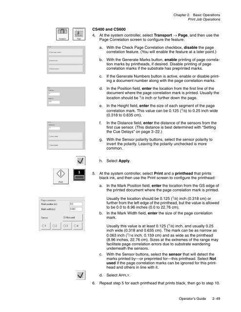
5. At the system controller, select Print and a printhead that prints<br />
black ink, and then use the Print screen to configure the printhead:<br />
a. In the Mark Position field, enter the location from the GS edge of<br />
the printed document where the page correlation mark is printed.<br />
Usually the location should be 0.125 ( 1 /8) inch (0.318 cm) or<br />
further from the left edge of the printhead, but the value is allowed<br />
to be 0.0 to 8.96 inches (0.0 to 22.76 cm).<br />
b. In the Mark Width field, enter the size of the page correlation<br />
mark.<br />
Usually this value is at least 0.125 ( 1 /8) inch, and usually 0.25<br />
inch wide (0.318 and 0.635 cm). The mark can be as narrow as<br />
0.063 inch ( 1 /16 inch, 0.159 cm) and as wide as the printhead<br />
(8.96 inches, 22.76 cm). Sizes at the extremes of the range may<br />
facilitate page correlation errors due to substrate wandering<br />
underneath the sensors.<br />
c. With the Sensor buttons, select the sensor that will detect the<br />
marks printed by—or preprinted for—this printhead. Select Not<br />
used if the page correlation marks can be ignored for this printhead<br />
and others in line with it.<br />
d. Select APPLY.<br />
6. Repeat step 5 for each printhead that prints black, then go to step 10.<br />
Operator’s <strong>Guide</strong> 2-49