

Design of X-Band FMCW Short Range Radar - Microwave and ...
Design of X-Band FMCW Short Range Radar - Microwave and ...
Design of X-Band FMCW Short Range Radar - Microwave and ...

Create successful ePaper yourself
Turn your PDF publications into a flip-book with our unique Google optimized e-Paper software.
<strong>Design</strong> <strong>of</strong> X-<strong>B<strong>and</strong></strong> <strong>FMCW</strong> <strong>Short</strong> <strong>Range</strong> <strong>Radar</strong><br />
Dong-hun Shin*<br />
Dept. <strong>of</strong> Electrical Engineering<br />
KAIST<br />
Daejeon, Korea<br />
husido@kaist.ac.kr<br />
Seong-ook Park<br />
Dept. <strong>of</strong> Electrical Engineering<br />
KAIST<br />
Daejeon, Korea<br />
sopark@ee.kaist.ac.kr<br />
Abstract— This paper researches on a X-b<strong>and</strong> <strong>FMCW</strong> short<br />
range radar. It has 160us sweep time <strong>and</strong> 600MHz b<strong>and</strong>width.<br />
The gain variable amplifier is used to remove the internal noise<br />
<strong>and</strong> compensate the path-loss. <strong>Range</strong> resolution is 25cm <strong>and</strong><br />
measurement data has less than 17cm error.<br />
Keywords-component; formatting; X-b<strong>and</strong>, SRR, <strong>FMCW</strong>,<br />
<strong>Radar</strong><br />
I. INTRODUCTION<br />
The range measurement <strong>and</strong> tracking system technology is<br />
classified according to source type. Ultrasound radar <strong>and</strong><br />
microwave radar are widely used. Ultrasound radar can<br />
measure accurate range with less than 10cm range resolution<br />
<strong>and</strong> is mainly used in robotics <strong>and</strong> industrial equipment. But,<br />
this radar is sensitive to the weather condition <strong>and</strong> range<br />
resolution is decreased in bad condition such as fog, rain,<br />
temperature, etc.<br />
The microwave radar can measure the distance <strong>and</strong><br />
acquisition <strong>of</strong> rough shape <strong>of</strong> the obstacles in any weather<br />
condition.[1] <strong>Microwave</strong> radar system used a short pulse signal<br />
or continuous-wave signals for the range detection. Pulse radar<br />
can detect the distance <strong>of</strong> multiples targets. However, it needs<br />
high power source to detect an object. In contrast, frequency<br />
modulation continuous wave (<strong>FMCW</strong>) radar can detect the<br />
distance <strong>of</strong> multiple targets <strong>and</strong> the speed <strong>of</strong> a moving object<br />
with lower power. In addition, it can be easily implemented<br />
due to the simple structure.[2] The microwave radar has a high<br />
technical accuracy for Precision range measurement <strong>and</strong><br />
tracking.[2-5]<br />
The size <strong>of</strong> the microwave radar system can be reduced by<br />
using higher frequency. But, some disadvantages are expensive<br />
<strong>and</strong> difficulty <strong>of</strong> producing. Regardless <strong>of</strong> the center frequency,<br />
short-range radar requires sufficient b<strong>and</strong>width in order to<br />
improve the distance resolution, but sufficient b<strong>and</strong>width is not<br />
allowed. So a compromise is needed in frequency b<strong>and</strong><br />
selection.<br />
Proposed <strong>Radar</strong> system is based on microwave <strong>FMCW</strong> <strong>and</strong><br />
has 600MHz b<strong>and</strong>width in x-b<strong>and</strong> with under 0dBm output<br />
power<br />
II.<br />
SHORT RANGE RADAR SYSTEM<br />
A. System Architecture<br />
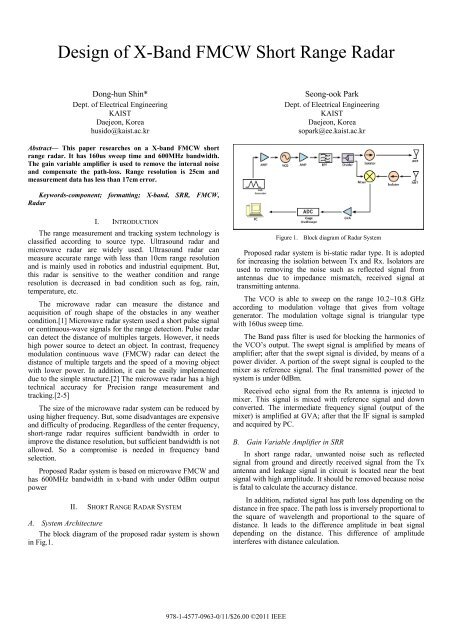
The block diagram <strong>of</strong> the proposed radar system is shown<br />
in Fig.1.<br />
Figure 1. Block diagram <strong>of</strong> <strong>Radar</strong> System<br />
Proposed radar system is bi-static radar type. It is adopted<br />
for increasing the isolation between Tx <strong>and</strong> Rx. Isolators are<br />
used to removing the noise such as reflected signal from<br />
antennas due to impedance mismatch, received signal at<br />
transmitting antenna.<br />
The VCO is able to sweep on the range 10.2~10.8 GHz<br />
according to modulation voltage that gives from voltage<br />
generator. The modulation voltage signal is triangular type<br />
with 160us sweep time.<br />
The <strong>B<strong>and</strong></strong> pass filter is used for blocking the harmonics <strong>of</strong><br />
the VCO’s output. The swept signal is amplified by means <strong>of</strong><br />
amplifier; after that the swept signal is divided, by means <strong>of</strong> a<br />
power divider. A portion <strong>of</strong> the swept signal is coupled to the<br />
mixer as reference signal. The final transmitted power <strong>of</strong> the<br />
system is under 0dBm.<br />
Received echo signal from the Rx antenna is injected to<br />
mixer. This signal is mixed with reference signal <strong>and</strong> down<br />
converted. The intermediate frequency signal (output <strong>of</strong> the<br />
mixer) is amplified at GVA; after that the IF signal is sampled<br />
<strong>and</strong> acquired by PC.<br />
B. Gain Variable Amplifier in SRR<br />
In short range radar, unwanted noise such as reflected<br />
signal from ground <strong>and</strong> directly received signal from the Tx<br />
antenna <strong>and</strong> leakage signal in circuit is located near the beat<br />
signal with high amplitude. It should be removed because noise<br />
is fatal to calculate the accuracy distance.<br />
In addition, radiated signal has path loss depending on the<br />
distance in free space. The path loss is inversely proportional to<br />
the square <strong>of</strong> wavelength <strong>and</strong> proportional to the square <strong>of</strong><br />
distance. It leads to the difference amplitude in beat signal<br />
depending on the distance. This difference <strong>of</strong> amplitude<br />
interferes with distance calculation.<br />
978-1-4577-0963-0/11/$26.00 ©2011 IEEE
Figure 2. Characteristic <strong>of</strong> Gain Variable Amp<br />
In this paper, gain variable amplifier is used to remove<br />
noise <strong>and</strong> compensate the path loss. Fig.2 shows characteristic<br />
<strong>of</strong> GVA. GVA has different gain depending on the frequency.<br />
III. RANGE MEASUREMENT<br />
To evaluate the performance <strong>of</strong> <strong>FMCW</strong> radar, a set <strong>of</strong><br />
simple test has been conducted. The specifications <strong>of</strong> the<br />
proposed <strong>FMCW</strong> radar are summarized in Table. Ⅰ . The<br />
microwave signals are transmitted <strong>and</strong> received via two<br />
pyramidal horn antennas (Gain : 22dBi, -3dB beam-width : 17 o<br />
@ 10.5GHz). The operation <strong>of</strong> the <strong>FMCW</strong> system was verified<br />
using a 50 x 50 cm2 piece <strong>of</strong> flat aluminum plate as a target.<br />
The target is positioned in front <strong>of</strong> antennas at intervals <strong>of</strong><br />
10cm from 0.5m to 5m. The beat frequency is achieved<br />
according to varying the location <strong>of</strong> the target using <strong>FMCW</strong><br />
radar.<br />
The result <strong>of</strong> measurement is shown in Fig.3. The solid line<br />
is measured result <strong>and</strong> dash line is ideally expected result.<br />
The measured range <strong>and</strong> the actual position <strong>of</strong> the target<br />
have compared. The maximum measurement error is less than<br />
17cm.<br />
Figure 3. <strong>Range</strong> measurement<br />
IV. CONCLUSION.<br />
<strong>Short</strong> range radar system has been presented. The proposed<br />
<strong>FMCW</strong> short range radar has 600MHz b<strong>and</strong>width <strong>and</strong> 160us<br />
sweep time (80us rising sweep <strong>and</strong> 80us falling sweep) with<br />
triangular sweep type. The GVA is used to remove unwanted<br />
noise <strong>and</strong> compensate the path-loss. And beat frequency signal<br />
was achieved according to the location <strong>of</strong> target.<br />
The operative frequency range <strong>and</strong> the radiated power<br />
follow the most recent international recommendations <strong>and</strong> it is<br />
possible to classify the system as a low power device for radio<br />
determination. The system has range error less than 17cm in<br />
5m range. This system can be implemented in many functions<br />
such as the parking aids, the stop-<strong>and</strong> go <strong>and</strong> the pre alarm <strong>of</strong><br />
the air bags.<br />
ACKNOWLEDGMENT<br />
This work was supported by the National IT Industry<br />
Promotion Agency (NIPA) through the project <strong>of</strong> rear detection<br />
microwave radar for construction equipment under contract<br />
ITAA1350100200020001000000000.<br />
TABLE I. SPECIFICATIONS OF <strong>FMCW</strong> RADAR<br />
Frequency<br />
10.2~10.8GHz<br />
<strong>B<strong>and</strong></strong>width<br />
600MHz in X-<strong>B<strong>and</strong></strong><br />
<strong>Range</strong> Resolution 0.25m<br />
Sweep type<br />
Triangular<br />
Sweep time<br />
160us<br />
Sampling Frequency 1Mbs<br />
Target <strong>Range</strong> 0.5~5m<br />
Target 50 x 50 cm 2 Aluminum<br />
Antennas<br />
X-<strong>B<strong>and</strong></strong> Horn Antenna<br />
REFERENCES<br />
[1] L. Giubbolini “A <strong>Microwave</strong> Imaging <strong>Radar</strong> in the Near Field for Anti<br />
collision(MIRANDA)” Trans. on M.T.A.T. vol. 47, No. 9 pp. 1891-<br />
1900, September 1999.<br />
[2] A.Chares, M. Charbit, J. Prada, A. Servel, M. Attia, “Frequency<br />
Modulated Continuous Wave <strong>Radar</strong> signal processing to improve active<br />
safety features.” IMeche, pp81-86, 1994.<br />
[3] Stove, A. G. “Linear <strong>FMCW</strong> radar techniques, IEEE Proceedings –F,<br />
Vol. 139, pp. 343-350, No.5 October1992K. Elissa, “Title <strong>of</strong> paper if<br />
known,” unpublished.<br />
[4] Igor V Komarov, Fundamentals <strong>of</strong> <strong>Short</strong> –range FM <strong>Radar</strong>, Artech<br />
House, 289pages, 2003.<br />
[5] M.I. Skolnik, <strong>Radar</strong> H<strong>and</strong>book, 3th Ed. Newyork; McGraw-Hill , 2008


