
You also want an ePaper? Increase the reach of your titles
YUMPU automatically turns print PDFs into web optimized ePapers that Google loves.
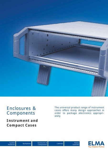
Enclosures &<br />
Components<br />
Instrument and<br />
Compact Cases<br />
The universal product range of instrument<br />
cases offers many design approaches in<br />
order to package electronics appropriately.<br />
System<br />
Platforms<br />
Backplanes<br />
Enclosures &<br />
Components<br />
Cabinets<br />
Rotary<br />
Switches
Local Service – global resources<br />
Switzerland USA Germany United Kingdom France Israel China Romania<br />
Elma is a global manufacturer of products for housing electronic systems.<br />
The company provides everything from components such as modular enclosures,<br />
cabinets and backplanes up to complete standard or custom system platforms.<br />
Elma also manufactures precision rotary switches. The company offers fast,<br />
flexible response to customer needs and extensive practical knowledge in<br />
tailoring solutions to specific applications.<br />
Founded in 1960, Elma is an industry innovator in the design and manufacture of electronic enclosures<br />
and passive electronic components. With vast expertise in Eurocard-based platforms, standard<br />
architectures include AdvancedTCA, CompactPCI, MicroTCA, Rugged COTS/ATR, VME, VME64x,<br />
VPX, VXI, VXS, and more. The company also tailors customised solutions to individual applications<br />
ensuring fast and cost-effective results. As a global company, Elma has production and assembly<br />
facilities in 8 countries and has representatives in over 40 countries. Elma has a broad base of<br />
customers in diverse industries such as telecommunications, industrial control, medical electronics,<br />
defense and aerospace.<br />
We provide products superior in quality, reliability, performance, and consistently presents new,<br />
innovative designs to the market. Elma also offers design and integration services backed by<br />
responsive and knowledge able technical support.<br />
Our leading quality level is reached through training of all employees and following of<br />
systematic procedures per ISO 9001 standards to which Elma has been registered.<br />
Why<br />
choose Elma?<br />
Flexibility<br />
Experience<br />
Compatibility<br />
Global Resources<br />
Elma tailors solutions to individual applications to ensure fast and costeffective<br />
results.<br />
Extensive practical experience in packaging electronic systems is used<br />
to minimise the time taken to develop new customised solutions without<br />
compromising system performance or reliability.<br />
Because the two key electromechanical components – enclosures<br />
and backplanes – are made in-house, Elma guarantees compatibility,<br />
consistency and reliability.<br />
With manufac turing in Europe, Asia and the USA, customers benefit from<br />
local service backed by global resources.<br />
2<br />
Elmaset<br />
www.elma.com
Custom Solutions<br />
Custom Solutions<br />
Customisation is the standard at Elma. With an extensive offering of modular standard<br />
products as a foundation, we are able to leverage existing solutions and proven design<br />
concepts to meet any custom application. This approach ensures that Elma will provide<br />
quality, compliant solutions with significantly reduced lead time, cost and risk.<br />
Combined with our integration capability for both embedded systems and switches,<br />
we provide a single solution to your outsourcing needs.<br />
Allow us to take your latest product from prototype to production quickly, cost<br />
effectively and with reduced risk.<br />
Design Capabilities<br />
Elma has been a leader in design innovation for over 45 years. We use advanced design<br />
software and equipment to perfect your design. We can utilise our vast resource of experienced<br />
designers and engineers from facilities all over the world. The result is a superb<br />
design solution, completed to your specifications in a timely and cost-efficient manner.<br />
Production<br />
Capabilities<br />
From base components to fully-integrated computing systems, Elma can be your<br />
solution partner each step of the way. With production and assembly facilities world wide,<br />
we can meet nearly any need – whether prototypes or high volumes, quickturn deliveries,<br />
or highly complex custom designs.<br />
Custom system platforms<br />
Over 20 years of expertise in system design with emphasis on thermal management<br />
Specialists in EMC, shock/vibration, system monitoring, reliability and maintainability<br />
Applications for industrial and rugged environment<br />
Custom backplanes<br />
Modified standards for all PICMG and VITA specifications<br />
NSC (non standard-based custom) design<br />
Proven, reliable high-speed designs with data rates up to 10 Gbps per differential pair<br />
Custom enclosures & components<br />
Modified standards for IEC, IEEE, ATCA, MicroTCA mechanics or proprietary solutions<br />
IP protection classes<br />
EMC security<br />
Custom cabinets<br />
Industrial, Rugged, Datacom/Server, or Shielded<br />
Highly complex or unusual configurations in any volume<br />
Silk screening, painting, tool making, validation testing, and agency certification<br />
Custom rotary switches<br />
Modifiable switches & LEDs<br />
Integration of switches, panels and other components<br />
Custom switch bracket fabrication<br />
www.elma.com Elmaset<br />
3
B<br />
Chapter Overview<br />
1. Unibox 14<br />
Universal case usable as sub rack<br />
or as desktop case<br />
2. <strong>Stylebox</strong> <strong>15</strong><br />
Elegantly designed EMC desktop or<br />
19” case with excellent product features<br />
3. Classicbox 32<br />
The classic of the desktop cases now in<br />
a revised version<br />
1<br />
Elmaset<br />
www.elma.com
B<br />
4. Guardbox 33<br />
Rugged EMC compact case with protection<br />
class up to IP65<br />
5. Varietybox 35<br />
Compact case with a very large variability<br />
and unlimited form factor<br />
www.elma.com Elmaset<br />
2
1: Unibox 14<br />
1.1 Unibox 14 Overview B | 1_3<br />
1.1.1 Complete Unibox 14 Kits B | 1_4<br />
B<br />
1.2 Frame for Unibox 14 B | 1_7<br />
1.2.1 Width B | 1_7<br />
1.2.2 Height B | 1_7<br />
1.2.3 Depth B | 1_8<br />
1.3 Cover Panel for Unibox 14 B | 1_9<br />
1.3.1 Top Cover Panel B | 1_9<br />
1.3.2 Bottom Cover Panel with Attached Feet B | 1_10<br />
1.3.3 Side Panels B | 1_10<br />
1.3.4 Drawing B | 1_11<br />
1.4 Adaptation Kits B | 1_12<br />
1.4.1 Adaptation Kit a B | 1_12<br />
1.4.2 Adaptation Kit b B | 1_13<br />
1.4.3 Adaptation Kit c B | 1_13<br />
1.4.4 Adaptation Kit d B | 1_14<br />
1.4.5 Adaptation Kit e B | 1_14<br />
1.4.6 Additional Extrusions Recessed Card Mounting B | 1_14<br />
1.4.7 Tapped Strips B | 1_<strong>15</strong><br />
1.4.8 Edge Connector Extrusion 66-145-xx B | 1_<strong>15</strong><br />
1.4.9 Edge Connector Extrusion 66-147-xx B | 1_<strong>15</strong><br />
1.5 Assembly Accessories B | 1_16<br />
1.5.1 Front Sub Division Vertical 6 U / 3 U B | 1_16<br />
1.5.2 Horizontal Card Mounting Kit B | 1_17<br />
B | 1_1<br />
Elmaset<br />
www.elma.com
1: Unibox 14<br />
1.6 General Accessories B | 1_19<br />
1.6.1 Perforated Cover Plates B | 1_19<br />
1.6.2 Mounting Chassis B | 1_20<br />
1.6.3 Earthing Set B | 1_22<br />
1.6.4 Card Guides IEC B | 1_23<br />
1.6.5 Flat Front Panels B | 1_25<br />
1.6.6 Fan Front Panel 84 HP for Vertical Ventilation B | 1_26<br />
B<br />
1.6.7 Fan Front Panel for Horizontal Ventilation B | 1_27<br />
1.6.8 Fan Front Panels for Direct Fan Mounting B | 1_27<br />
1.6.9 Top / Bottom-Hinged Front Panel B | 1_28<br />
1.6.10 Side-Hinged Front Panel B | 1_29<br />
1.6.11 Extruded Front Panels B | 1_30<br />
1.6.12 Front Panel with Cutout for IEC Ejector Handle B | 1_32<br />
1.6.13 Card Locks and Card Handles B | 1_33<br />
1.6.14 Card Holder acc. to IEC Standard B | 1_35<br />
1.6.<strong>15</strong> Middle Part B | 1_36<br />
1.6.16 Protective Cover for 6 U Printed Board B | 1_36<br />
1.6.17 Spacers B | 1_37<br />
1.6.18 Mounting Plates B | 1_38<br />
1.6.19 Hexagonal Spacers M3 Thread B | 1_38<br />
1.6.20 Covering Caps B | 1_38<br />
1.6.21 Mounting Bracket B | 1_39<br />
1.7 Extrusions B | 1_40<br />
1.7.1 Front Extrusions B | 1_40<br />
1.7.2 Height Extrusions B | 1_41<br />
1.7.3 Depth Extrusions B | 1_42<br />
1.7.4 Internal Extrusions B | 1_43<br />
1.7.5 Edge Connector Extrusions B | 1_45<br />
www.elma.com Elmaset<br />
B | 1_2
B<br />
1: Unibox 14<br />
1.1 Unibox 14 Overview<br />
• Usable as sub rack or as desktop case<br />
• Card mounting from front and back<br />
• Dimensions according to IEC 60297<br />
• Numerous adaptation options<br />
• The extruded aluminium frame can be used as a sub rack or, when clad with a set of easily fitted cover<br />
plates, transformed into a small table-top instrument case<br />
• Rack mount complete with cover plates possible<br />
• Panels and modules can be mounted from the front or the back<br />
• Adaptation kits available for mounting modules<br />
• Fitting of telescopic rails or guide rails only possible for 81 HP (upon request only)<br />
• Can be employed as a desktop case or sub rack for mounting in 19" cabinets<br />
• In either configuration it will accept PCBs and plug-in units based on standard card sizes conforming<br />
to DIN 41494 or IEC 60297<br />
• Recessed mounting with a pitch of 7.5 mm is possible<br />
• With metal cover plates fitted, the sub rack is suitable for use where it is subjected to continous vibration<br />
Side panel<br />
Top cover panel<br />
Trim strips<br />
Vertical section, rear<br />
Vertical section, rear<br />
Front extrusion 66-111<br />
with/without<br />
U handles<br />
Depth extrusion<br />
66-177<br />
Vertical extrusion front<br />
Bottom cover panel,<br />
complete with feet<br />
Tapped strip<br />
19” Vertical section, front<br />
B | 1_3<br />
Elmaset<br />
www.elma.com
1: Unibox 14<br />
1.1.1 Complete Unibox 14 Kits<br />
You can find the most used complete kits below.<br />
With the new order structure (see “Configuration” B|1_6) you have however the possibility of configure your individual<br />
housing in different steps. Use this offer or contact us for further information or any other help.<br />
1.1.1.1 Unibox 14 Frame Kit<br />
• Scope of delivery:<br />
• 2 front height extrusions (detail see 1.2.2)<br />
• 2 rear height extrusions (detail see 1.2.2)<br />
• 4 front/rear extrusions (detail see 1.2.1)<br />
• 4 depth extrusions (detail see 1.2.3)<br />
• 2 handles 9mm (detail see 1.2.2)<br />
• 1 label strip (detail see 1.2.1)<br />
• 1 set assembly material<br />
• Tapped strips have to be ordered separately, see below<br />
• Front / rear panel have to be ordered separately, see 1.6.5<br />
• Cover panels have to be ordered separately, see below or 1.3<br />
B<br />
Frame without 19” vertical sections, with handles<br />
Height<br />
2 U<br />
3 U<br />
4 U<br />
6 U<br />
Width<br />
Depth<br />
232.6 mm<br />
9.<strong>15</strong>”<br />
292.6 mm<br />
11.51”<br />
412.6 mm<br />
16.24”<br />
532.6 mm<br />
20.96”<br />
42 HP 14B522 14B523 - -<br />
63 HP 14B422 14B423 14B425 -<br />
84 HP 14B122 14B123 14B125 -<br />
42 HP 14B532 14B533 - -<br />
63 HP 14B432 14B433 14B435 -<br />
84 HP 14B132 14B133 14B135 14B137<br />
42 HP 14B542 14B543 - -<br />
63 HP 14B442 14B443 14B445 -<br />
84 HP 14B142 14B143 14B145 14B147<br />
42 HP 14B562 14B563 - -<br />
63 HP 14B462 14B463 14B465 -<br />
84 HP 14B162 14B163 14B165 14B167<br />
Frame with 19” vertical sections, with handles<br />
Depth<br />
Height Width 232.6 mm<br />
9.<strong>15</strong>”<br />
292.6 mm<br />
11.51”<br />
412.6 mm<br />
16.24”<br />
532.6 mm<br />
20.96”<br />
2 U 84 HP 14B022 14B023 14B025 -<br />
3 U 84 HP 14B032 14B033 14B035 14B037<br />
4 U 84 HP 14B042 14B043 14B045 14B047<br />
6 U 84 HP 14B062 14B063 14B065 14B067<br />
7 U 84 HP - - 14B075 14B077<br />
1.1.1.2 Tapped Strips<br />
• Steel, zinc-plated<br />
• Scope of delivery:<br />
• 10 tapped strips<br />
Size 42 HP 63 HP 84 HP<br />
M2.5 / 2 x 6 mm 63-057 63-062 63-089<br />
www.elma.com Elmaset<br />
B | 1_4
1: Unibox 14<br />
1.1.1.3 Unibox 14 Cover panel Kit<br />
• Scope of delivery:<br />
• 1 top cover panel, solid, light grey (detail see 1.3.1)<br />
• 1 bottom cover panel with feet, solid, light grey (detail see 1.3.2)<br />
• 2 side panels, solid, light grey (detail see 1.3.3)<br />
• 1 set of trim strips (detail see 1.3.3.1)<br />
• 1 set of rubber bands (detail see 1.3.3.2)<br />
• 1 set assembly material<br />
B<br />
Height<br />
Width<br />
Depth<br />
232.6 mm<br />
9.<strong>15</strong>”<br />
292.6 mm<br />
11.51”<br />
412.6 mm<br />
16.24”<br />
532.6 mm<br />
20.96”<br />
42 HP 14Z422-10 14Z423-10 - -<br />
2 U<br />
63 HP 14Z322-10 14Z323-10 14Z325-10 -<br />
84 HP 14Z122-10 14Z123-10 14Z125-10 -<br />
42 HP 14Z432-10 14Z433-10 14Z435-10 -<br />
3 U<br />
63 HP 14Z332-10 14Z333-10 14Z335-10 -<br />
84 HP 14Z132-10 14Z133-10 14Z135-10 14Z137-10<br />
42 HP 14Z442-10 14Z443-10 14Z445-10 -<br />
4 U<br />
63 HP 14Z342-10 14Z343-10 14Z345-10 -<br />
84 HP 14Z142-10 14Z143-10 14Z145-10 14Z147-10<br />
42 HP 14Z462-10 14Z463-10 14Z465-10 -<br />
6 U<br />
63 HP 14Z362-10 14Z363-10 14Z365-10 -<br />
84 HP 14Z162-10 14Z163-10 14Z165-10 14Z167-10<br />
7 U 84 HP - 14Z173-10 14Z175-10 14Z177-10<br />
B | 1_5<br />
Elmaset<br />
www.elma.com
1: Unibox 14<br />
Configuration<br />
Frame<br />
Width<br />
1.2.1<br />
- 42 HP / 63 HP / 84 HP<br />
(incl. assembly material))<br />
1.2.1.2 Label Strips<br />
Height<br />
1.2.2<br />
- 2 U / 3 U / 4 U / 6 U / 7 U<br />
- slim/19"<br />
- with/without holes for handles<br />
B<br />
1.2.2.1 Handles<br />
Depth<br />
1.2.3<br />
- 232.6 mm, 292.6 mm,<br />
532.6 mm, 412.6 mm<br />
Covers<br />
Top Cover<br />
1.3.1<br />
Assembly Material<br />
- light grey or black<br />
- solid/perforated<br />
- width 42 HP, 63 HP, 84 HP<br />
- formed for backplane mounting<br />
- for top cover<br />
Bottom Cover<br />
1.3.2<br />
Assembly Material<br />
- light grey or black<br />
- solid/perforated<br />
- width 42 HP, 63 HP, 84 HP<br />
- formed for backplane mounting<br />
- for bottom cover<br />
Side Panels<br />
2.2.6 / 2.3.6<br />
Trim Strip<br />
1.3.3.1<br />
- light grey or black<br />
- solid/perforated<br />
- height 2 U, 3 U, 4 U, 6 U, 7 U<br />
- depth 232.6 mm, 292.6 mm,<br />
412.6 mm, 532.1 mm<br />
- colour: light grey or black<br />
- depth: 232.6 mm, 292.6 mm,<br />
412.6 mm, 532.6 mm<br />
Assembly Material<br />
1.3.3.2<br />
- for side panels and trim strips<br />
1.4 Adaptation Kits<br />
1.5 Assembly Accessories<br />
1.6 General Accessories<br />
1.7 Extrusions<br />
www.elma.com Elmaset<br />
B | 1_6
B<br />
1: Unibox 14<br />
1.2 Frame for Unibox 14<br />
• Usable as sub rack<br />
• Different possibilities of card mounting<br />
• Dimensions according to IEC 60297<br />
1.2.1 Width<br />
• Scope of delivery:<br />
• 4 front/rear extrusions<br />
• 4 tapped strips M2.5<br />
• Assembly material: 1 set of screws cross recessed M4x10 (63-109)<br />
42 HP 63 HP 84 HP<br />
14M001 14M002 14M003<br />
Label Strips<br />
• Scope of delivery:<br />
• 1 label strip consisting of 4 single tapes<br />
Scope of Delivery<br />
2 pcs. each<br />
(upper and lower)<br />
42 HP<br />
(01-42/42-01)<br />
63 HP<br />
(01-63/63-01)<br />
63-142 63-143 63-046<br />
84 HP<br />
(01-84/84-01)<br />
1.2.2 Height<br />
• Scope of delivery:<br />
• 2 height extrusions<br />
• 2 sets have to be ordered (for front and rear)<br />
Description 2 U 3 U 4 U 6 U 7 U<br />
Slim without holes for handle 14M004 14M005 14M006 14M007 14M008<br />
Slim with holes for handle 14M009 14M010 14M011 14M012 14M013<br />
19" section without holes for handle 14M014 14M0<strong>15</strong> 14M016 14M017 14M018<br />
19" section with holes for handle 14M019 14M020 14M021 14M022 14M023<br />
1.2.2.1 Handles<br />
• Scope of delivery:<br />
• 1 handle<br />
• 2 handles have to be ordered per case<br />
• 2 screws per handle have to be ordered separately<br />
Description 2 U 3 U 4 U 6 U 7 U<br />
9 mm 60-527 60-528 60-529 60-531 60-529<br />
Universal handle<br />
(for 19” section only)<br />
60-553 60-554 60-556 60-554<br />
Screws cross sloted countersunk M4 x 10<br />
1 pc. 5342-10<br />
100 pcs. 1906-24<br />
B | 1_7<br />
Elmaset<br />
www.elma.com
B<br />
1: Unibox 14<br />
1.2.3 Depth<br />
• Scope of delivery:<br />
• 4 depth extrusions<br />
232.6 mm<br />
9.<strong>15</strong>"<br />
292.6 mm<br />
9.<strong>15</strong>"<br />
412.6 mm<br />
16.24"<br />
532.6 mm<br />
20.96"<br />
14M024 14M025 14M026 14M027<br />
Line drawings for sub rack without 19" vertical sections<br />
Plan view<br />
B<br />
b<br />
Side view section<br />
Front view<br />
Hs<br />
41<br />
H<br />
7.5 t<br />
T<br />
b<br />
B<br />
Heights<br />
for H mm H inch Hs mm Hs inch<br />
2 U 88.05 3.46 68.05 2.67<br />
3 U 132.50 5.21 112.50 4.42<br />
4 U 176.95 6.96 <strong>15</strong>6.95 6.17<br />
6 U 265.85 10.46 245.85 9.67<br />
7 U 310.30 12.21 290.30 11.42<br />
Width<br />
for B mm B inch b mm b inch<br />
42 HP 234.32 9.22 213.32 8.39<br />
63 HP 341.00 13.42 320.00 12.59<br />
84 HP 447.68 17.62 426.68 16.79<br />
Depths<br />
T mm T inch t mm t inch<br />
244.6 9.62 232.6 9.<strong>15</strong><br />
304.6 11.99 292.6 11.51<br />
424.6 16.71 412.6 16.24<br />
544.6 21.44 532.6 20.96<br />
Line drawings for sub rack with 19" vertical sections<br />
Plan view<br />
B<br />
b<br />
Side view section<br />
Front view<br />
Hs<br />
e<br />
H<br />
Heights<br />
for H mm H inch Hs mm H inch<br />
2 U 88.05 3.46 68.05 2.67<br />
3 U 132.50 5.21 112.50 4.42<br />
4 U 176.95 6.96 <strong>15</strong>6.95 6.17<br />
6 U 265.85 10.46 245.85 9.67<br />
7 U 310.30 12.21 290.30 11.42<br />
Width<br />
for B mm B inch b mm b inch<br />
84 HP 447.68 17.62 426.68 16.79<br />
3<br />
41<br />
7.5<br />
t<br />
T<br />
b<br />
465.9<br />
482.6<br />
Depths<br />
T mm T inch t mm t inch<br />
244.6 9.62 232.6 9.<strong>15</strong><br />
304.6 11.99 292.6 11.51<br />
424.6 16.71 412.6 16.24<br />
544.6 21.44 532.6 20.96<br />
www.elma.com Elmaset<br />
B | 1_8
B<br />
1: Unibox 14<br />
1.3 Cover Panel for Unibox 14<br />
• One sided film laminated sheet aluminium 1.5 mm<br />
• Perforated top and bottom covers are available for better ventilation<br />
• Bottom cover plates are supplied with feet attached<br />
• Sub rack can be mounted complete with cover plates in a cabinet<br />
• Formed top and bottom cover panels available for 84 HP for accomodation of backplane (drawing see 1.3.4.1)<br />
1.3.1 Top Cover Panel<br />
• Scope of delivery:<br />
• 1 top cover panel<br />
Description<br />
Solid, light grey<br />
Depth<br />
Width<br />
232.6mm<br />
9.<strong>15</strong>"<br />
292.6mm<br />
11.51"<br />
412.6mm<br />
16.24"<br />
— — — —<br />
Solid, graphite-black 14-817-60 14-818-60 14-820-60 —<br />
42 HP<br />
Perforated, light grey 14-817-11 14-818-11 14-820-11 —<br />
Perforated, graphite-black 14-817-61 14-818-61 14-820-61 —<br />
Solid, light grey<br />
— — — —<br />
Solid, graphite-black 14-812-60 14-813-60 14-8<strong>15</strong>-60 —<br />
63 HP<br />
Perforated, light grey 14-812-11 14-813-11 14-8<strong>15</strong>-11 —<br />
Perforated, graphite-black 14-812-61 14-813-61 14-8<strong>15</strong>-61 —<br />
Solid, light grey<br />
— — — —<br />
532.6mm<br />
20.96"<br />
Solid, graphite-black 14-802-60 14-803-60 14-805-60 14-828-60<br />
Perforated, light grey 14-802-11 14-803-11 14-805-11 14-828-11<br />
84 HP<br />
Perforated, graphite-black 14-802-61 14-803-61 14-805-61 14-828-61<br />
Solid, light grey, formed — 14-702-10 14-704-10 14-706-10<br />
Perforated, light grey, formed — 14-702-11 14-704-11 14-706-11<br />
Assembly Material<br />
• For mounting 1 top and 1 bottom cover onto the frame<br />
Description<br />
Part-No.<br />
1 set of cross recessed screws 63-111<br />
1 set of cross recessed screws for cranked version 63-195<br />
B | 1_9<br />
Elmaset<br />
www.elma.com
1: Unibox 14<br />
1.3.2 Bottom Cover Panel with Attached Feet<br />
1.3.3 Side Panels<br />
1.3.2 Bottom Cover Panel with Attached Feet<br />
• Scope of delivery:<br />
• 1 bottom cover panel<br />
Description<br />
Depth<br />
Width<br />
232.6mm<br />
9.<strong>15</strong>"<br />
292.6mm<br />
11.51"<br />
412.6mm<br />
16.24"<br />
532.6mm<br />
20.96"<br />
Solid, light grey<br />
— — — —<br />
Solid, graphite-black 14-867-60 14-868-60 14-870-60 —<br />
42 HP<br />
Perforated, light grey 14-867-11 14-868-11 14-870-11 —<br />
Perforated, graphite-black 14-867-61 14-868-61 14-870-61 —<br />
Solid, light grey<br />
— — — —<br />
Solid, graphite-black 14-862-60 14-863-60 14-865-60 —<br />
63 HP<br />
Perforated, light grey 14-862-11 14-863-11 14-865-11 —<br />
Perforated, graphite-black 14-862-61 14-863-61 14-865-61 —<br />
Solid, light grey<br />
— — — —<br />
Solid, graphite-black 14-852-60 14-853-60 14-855-60 14-848-60<br />
Perforated, light grey 14-852-11 14-853-11 14-855-11 14-848-11<br />
84 HP<br />
Perforated, graphite-black 14-852-61 14-853-61 14-855-61 14-848-61<br />
Solid, light grey, formed — 14-766-10 14-768-10 14-770-10<br />
Perforated, light grey, formed — 14-766-11 14-768-11 14-770-11<br />
Assembly Material<br />
• For mounting 1 top and 1 bottom cover onto the frame<br />
Description<br />
Part-No.<br />
1 set of cross recessed screws 63-111<br />
1 set of cross recessed screws for cranked version 63-195<br />
• Scope of delivery:<br />
• 1 side panel<br />
• 2 pieces have to be ordered (for left and right side)<br />
• Trim strips see 1.3.3.1<br />
• Assembly material see 1.3.3.2<br />
1.3.3 Side Panels<br />
Description<br />
Height 2 U 3 U 4 U 6 U 7 U<br />
Depth<br />
Solid, light grey 232.6 30-902-1 30-907-1 30-912-1 30-922-1 —<br />
Solid, graphite-black 9.<strong>15</strong>" 30-902-6 30-907-6 30-912-6 30-922-6 —<br />
Solid, light grey<br />
30-903-1 30-908-1 30-913-1 30-923-1 30-962-1<br />
292.6<br />
Solid, graphite-black 30-903-6 30-908-6 30-913-6 30-923-6 30-962-6<br />
11.51"<br />
Perforated, light grey 14-752-1 14-783-1 14-793-1 14-759-1 —<br />
Solid, light grey<br />
30-905-1 30-910-1 30-9<strong>15</strong>-1 30-925-1 14-603-10*<br />
412.6<br />
Solid, graphite-black 30-905-6 30-910-6 30-9<strong>15</strong>-6 30-925-6 —<br />
16.24"<br />
Perforated, light grey 14-754-1 14-785-1 14-795-1 14-761-1 —<br />
Solid, light grey<br />
— 30-988-1 30-989-1 30-991-1 14-613-10*<br />
Solid, graphite-black 532.6 — 30-988-6 30-989-6 30-991-6 —<br />
Perforated, light grey 20.96" — 14-787-1 14-797-1 14-763-1 —<br />
Perforated, graphite-black — 14-787-6 14-797-6 14-763-6 —<br />
*Assembly material for mounting 2 side panels 7 U, depth: 412.6/532.6 mm: 63-195<br />
B<br />
1.3.3.1 Trim Strips<br />
• Scope of delivery:<br />
• 4 trim strips<br />
Depth 232.6 mm 292.6 mm 412.6 532.6<br />
Description<br />
9.<strong>15</strong>" 11.51" 16.24" 20.96"<br />
Solid, light grey 30-932-1 30-933-1 30-935-1 30-944-1<br />
Solid, graphite-black 30-932-6 30-933-6 30-935-6 30-944-6<br />
1.3.3.2 Assembly Material for Side Panels and Trim Strips<br />
Description Depth mm Depth inch Part-No.<br />
1 set of rubber tubing 232.6 9.<strong>15</strong> 63-096<br />
1 set of rubber tubing 292.6 11.51 63-097<br />
1 set of rubber tubing 412.6 16.24 63-099<br />
1 set of rubber tubing 532.6 20.96 63-141<br />
www.elma.com Elmaset<br />
B | 1_10
1: Unibox 14<br />
1.3.4 Drawing<br />
1.3.4.1 Line Drawing Cover Panel Formed for Accomodation of Backplane<br />
t<br />
Extrusion 66-193-..<br />
for<br />
H<br />
mm<br />
inch<br />
B<br />
122.5<br />
122.5<br />
90 standard backplane max. 130<br />
H-2.5<br />
H+0.5<br />
Extrusion<br />
66-147-.. Extrusion 66-162-..<br />
Tapped strips<br />
(2x6 mm)<br />
DIN 41612<br />
H-7.2<br />
H-20<br />
H<br />
3 U 132.50 5.21<br />
4 U 176.95 6.96<br />
6 U 265.85 8.71<br />
7 U 310.30 10.46<br />
1.3.4.2 Line Drawing of Side Panel for Crossflow Ventilation<br />
Side panel 2U<br />
Case Depth t A B<br />
20<br />
33.7<br />
mm inch mm inch mm inch<br />
3 3<br />
292.6 11.51 225 8.85 292.3 11.50<br />
A<br />
412.6 16.24 345 13.58 412.3 16.23<br />
B<br />
532.6 20.96 465 18.30 532.3 20.95<br />
Side panel 3 U<br />
Side panel 4 U<br />
Side panel 6 U<br />
20 5<br />
70<br />
78.2<br />
10<br />
110<br />
122.7<br />
3 3<br />
A<br />
B<br />
3 3<br />
20<br />
A<br />
B<br />
20 10<br />
200<br />
211.7<br />
3 3<br />
A<br />
B<br />
B | 1_11<br />
Elmaset<br />
www.elma.com
B<br />
1: Unibox 14<br />
1.4 Adaptation Kits<br />
• Adaptation kits are used to subdivide the basic frame both in depth and height<br />
• Tapped strips have to be ordered separately, see 1.4.7<br />
Note:<br />
Information for Adaptation kits a - e:<br />
• 14-xxx- x for mounting:<br />
0 = standard extrusions, 66-144/66-124<br />
(when supplementary edge connector extrusions are also used, see 1.4.8)<br />
6 = backplane mounting 66-193<br />
(insulating strips see 1.7.4.3)<br />
• Scope of delivery is shown in blue in the following illustrations<br />
• Tapped strip see 1.4.7<br />
1.4.1 Adaptation Kit a<br />
• Range of Application:<br />
• Single eurocard depth 160 – 400 mm<br />
• Connector to IEC 60603-2/DIN 41617/MIL-C-21097<br />
• Motherboard<br />
• Modules, cassettes, plug-in units<br />
• Set for horizontal mounting of single, double triple eurocards, depth 160 + 400 mm<br />
• Crossflow ventilation with 3 U fan module<br />
• Drive mechanism receptacles 3 1 / 2 ”/5 1 / 4 ”<br />
3 U<br />
1.4.1 Adaptation Kit a<br />
• Scope of delivery:<br />
• 2 internal extrusions<br />
• 1 set assembly material<br />
Description 42 HP 63 HP 84 HP<br />
Front-mounting of single eurocards<br />
14-940-0 14-930-0 14-910-0<br />
14-940-6 14-930-6 14-910-6<br />
www.elma.com Elmaset<br />
B | 1_12
1: Unibox 14<br />
1.4.2 Adaptation Kit b<br />
• Range of Application:<br />
• Single eurocards, depth 160 – 400 mm<br />
• Connector to IEC 60603-2<br />
• Motherboard<br />
• Modules, cassettes, plug-in units<br />
• Vertical ventilation with 1 U fan module<br />
• Set for horizontal mounting of single, double, triple eurocards, depth 160 – 400 mm<br />
• Crossflow ventilation with 3 U fan module<br />
• Drive mechanism receptacles 3 1 / 2 ” / 5 1 / 4 ”<br />
B<br />
1.4.2 Adaptation Kit b<br />
• Scope of delivery:<br />
• 3 internal extrusions<br />
• 1 front extrusion<br />
• 2 depth dividers<br />
• 1 set assembly material<br />
Description Depth 84 HP<br />
mm<br />
inch<br />
Front-mounting of single eurocards<br />
in a 4 U case with possibility of crossflow ventilation<br />
292.6 11.51 14-913-05<br />
292.6 11.51 14-913-65<br />
412.6 16.24 14-9<strong>15</strong>-05<br />
412.6 16.24 14-9<strong>15</strong>-65<br />
1.4.3 Adaptation Kit c<br />
• Range of Application:<br />
• Double eurocards, depth 160 – 400 mm<br />
• Width dividin kit for single and double eurocards<br />
• Connector to IEC 60603-2<br />
• Motherboard<br />
• Modules, cassettes, plug-in units<br />
• Drive mechanism receptacles 5 1 / 4 ”<br />
1.4.3 Adaptation Kit c<br />
• Scope of delivery:<br />
• 2 internal extrusions<br />
• 2 divider sections<br />
• 1 centre extrusion<br />
• 1 set assembly material<br />
Description Depth 42 HP 63 HP 84 HP<br />
Front-mounting of double eurocards<br />
mm inch<br />
232.6 9.<strong>15</strong> 14-942-00 14-932-00 14-912-00<br />
232.6 9.<strong>15</strong> 14-942-60 14-932-60 14-912-60<br />
292.6 11.51 14-943-00 14-933-00 14-913-00<br />
292.6 11.51 14-943-60 14-933-60 14-913-60<br />
412.6 16.24 14-945-00 14-935-00 14-9<strong>15</strong>-00<br />
412.6 16.24 14-945-60 14-935-60 14-9<strong>15</strong>-60<br />
532.6 20.96 14-917-00<br />
532.6 20.96 14-917-60<br />
B | 1_13<br />
Elmaset<br />
www.elma.com
1: Unibox 14<br />
1.4.4 Adaptation Kit d<br />
• Range of Application:<br />
• Single eurocards, depth 160 – 400 mm<br />
• Connector to IEC 60603-2<br />
• Motherboard<br />
• Modules, cassettes, plug-in units<br />
• Drive mechanism receptacles 3 1 / 2 ” / 5 1 / 4 ”<br />
1.4.5 Adaptation Kit e<br />
1.4.4 Adaptation Kit d<br />
• Scope of delivery:<br />
• 4 internal extrusions<br />
• 2 front extrusions<br />
• 2 divider sections<br />
• 1 set assembly material<br />
Description Depth 42 HP 63 HP 84 HP<br />
mm inch<br />
232.6 9.<strong>15</strong> 14-942-01 14-932-01 14-912-01<br />
232.6 9.<strong>15</strong> 14-942-61 14-932-61 14-912-61<br />
292.6 11.51 14-943-01 14-933-01 14-913-01<br />
Front-mounting of single eurocards<br />
292.6 11.51 14-943-61 14-933-61 14-913-61<br />
in a 6 U case<br />
412.6 16.24 14-945-01 14-935-01 14-9<strong>15</strong>-01<br />
412.6 16.24 14-945-61 14-935-61 14-9<strong>15</strong>-61<br />
532.6 20.96 14-917-01<br />
532.6 20.96 14-917-61<br />
B<br />
• Range of Application:<br />
• Double eurocards,, depth 160 – 400 mm<br />
• Width dividing kit for single and double eurocards<br />
• Connectors to IEC 60603-2<br />
• Motherboard<br />
• Modules, cassettes, plug-in units<br />
• Vertical-flow ventilation with 1 U fan module<br />
• Drive mechanism receptacle 5 1 / 4 "<br />
1.4.5 Adaptation Kit e<br />
• Scope of delivery:<br />
• 3 internal extrusions<br />
• 1 front extrusion<br />
• 2 depth dividers<br />
• 2 divider sections<br />
• 1 centre extrusion<br />
• 2 sets assembly material<br />
Description Depth 84 HP<br />
mm<br />
inch<br />
292.6 11.51 14-913-03<br />
292.6 11.51 14-913-63<br />
Flush front-mounting of double eurocards in a 7<br />
U case with possibility of crossflow ventilation<br />
412.6 16.24 14-9<strong>15</strong>-03<br />
412.6 16.24 14-9<strong>15</strong>-63<br />
532.6 20.96 14-917-03<br />
532.6 20.96 14-917-63<br />
1.4.6 Additional Extrusions Recessed Card Mounting<br />
• For recessed mounting of Eurocards without individual front panels<br />
• Scope of delivery:<br />
• 2 internal extrusions<br />
• 1 set assembly material<br />
• For recessed card mounting two sets are necessary<br />
1.4.6 Additional Extrusions Recessed Card Mounting<br />
Description 42 HP 63 HP 84 HP<br />
3 U<br />
For frame width 14-940-0 14-930-0 14-910-0<br />
min. 37.5<br />
www.elma.com Elmaset<br />
B | 1_14
1: Unibox 14<br />
1.4.7 Tapped Strips<br />
• Steel, zinc-plated<br />
• Scope of delivery:<br />
• 10 tapped strips<br />
1.4.7.1 Tapped Strips for Use with Extrusion 66-144, 66-124<br />
Size 42 HP 63 HP 84 HP<br />
M2.5 / 2 x 6 mm 63-057 63-062 63-089<br />
B<br />
1.4.7.2 Tapped Strips for Use with Extrusion 66-193<br />
Size 42 HP 63 HP 84 HP<br />
M2.5 / 1.8 x 5 mm 63-081 63-082 63-084<br />
1.4.8 Edge Connector Extrusion 66-145-xx<br />
• For use with standard extrusion 66-144<br />
• Scope of delivery:<br />
• 1 aluminium extrusion, clear passivated (conductive)<br />
1.4.8 Supplementary Edge Connector Extrusion<br />
Description 8 HP 18 HP 28 HP 42 HP 63 HP 84 HP<br />
For edge connector, IEC<br />
60603-2<br />
1.4.8.1. Assembly Material<br />
Description<br />
66-145-40 66-145-41 66-145-42 66-145-63 66-145-65 66-145-52<br />
Part-No.<br />
Assembly material M2.5 (for 2 supplementary extrusions) 63-214<br />
1.4.9 Edge Connector Extrusion 66-147-xx<br />
• For use with extrusions for backplanes 66-193<br />
• Scope of delivery:<br />
• 1 aluminium extrusion, clear passivated (conductive)<br />
1.4.9 Edge Connector Extrusion<br />
Description 8 HP 18 HP 28 HP 42 HP 63 HP 84 HP<br />
For edge connector, IEC<br />
60603-2<br />
Assembly Material<br />
Description<br />
66-147-40 66-147-41 66-147-42 66-147-63 66-147-65 66-147-52<br />
Part-No.<br />
Assembly material M2.5 (for 2 supplementary extrusions) 63-214<br />
B | 1_<strong>15</strong><br />
Elmaset<br />
www.elma.com
B<br />
1: Unibox 14<br />
1.5 Assembly Accessories<br />
1.5.1 Front Sub Division Vertical 6 U / 3 U<br />
• Allows both single and double eurocards to be mounted together<br />
in a 6 U Unibox 14<br />
• Scope of delivery:<br />
• 1 divider extrusion front<br />
• 1 divider extrusion rear<br />
• 2 front extrusions<br />
• 2 internal extrusions<br />
• 1 set assembly material<br />
6 U<br />
• Tapped strip see below<br />
• Card guides see 1.6.4<br />
• Depth divider extrusion see 1.7.3.2<br />
c<br />
b<br />
a<br />
1.5.1 Front Sub Division Vertical 6 U / 3 U<br />
Usable<br />
Width b<br />
Width a 42 HP 63 HP 84 HP Part-No.<br />
21 HP c = 19 HP c = 40 HP c = 61 HP 14-979-2<br />
28 HP c = 12 HP c = 33 HP c = 54 HP 14-969-2<br />
32 HP c = 8 HP c = 29 HP c = 50 HP 14-959-2<br />
Tapped Strips for Front Extrusion<br />
Scope of Delivery Description Part-No.<br />
1 pc. tapped strip<br />
61-459<br />
M2.5 21 HP = 106.68 mm<br />
10 pcs. tapped strips 63-182<br />
1 pc. tapped strip<br />
61-458<br />
M2.5 28 HP = 142.24 mm<br />
10 pcs. tapped strips 63-183<br />
1 pc. tapped strip<br />
61-463<br />
M2.5 32 HP = 162.56 mm<br />
10 pcs. tapped strips 63-190<br />
www.elma.com Elmaset<br />
B | 1_16
B<br />
1: Unibox 14<br />
1.5.2 Horizontal Card Mounting Kit<br />
• For double eurocards (6 U)<br />
• Independent of card depth<br />
• The horizontal card mounting kit can be fitted recessed within<br />
the Unibox 14 by using two additional extrusions<br />
• Scope of delivery:<br />
• 4 distance plates (2 front / 2 rear)<br />
• 4 length extrusions (2 front / 2 rear)<br />
• 1 centre extrusion<br />
• 6 tapped strips M2.5<br />
• 1 set assembly material<br />
• Top and bottom cover plate when no overall fan front panel (1.5.2.1) is used<br />
• Top and bottom cover plate has to be ordered separately (see table)<br />
• Fan front panels for horizontal mounting kits see 1.5.2.1<br />
• Card guides see 1.6.4<br />
• Extruded front panels see 1.6.11<br />
Double eurocards = 52 HP<br />
Triple eurocards = 78 HP<br />
84 HP<br />
32 HP<br />
6 HP<br />
1.5.2 Horizontal Card Mounting Kit<br />
Mounting<br />
Height<br />
Usable<br />
Height<br />
IEC 60603-2 Backplane Cover plate<br />
top*<br />
Cover plate<br />
bottom*<br />
2 U 12 HP - 14-961-60 21N604-90 21N605-90<br />
3 U 20 HP 14-971-30 14-971-60 21N602-90 21N602-90<br />
4 U 28 HP - 14-981-60 21N602-90 21N603-90<br />
6 U 48 HP - 14-991-60 21N606-90 21N607-90<br />
* Assembly material for cover plate see 1.5.2.2<br />
B | 1_17<br />
Elmaset<br />
www.elma.com
1: Unibox 14<br />
1.5.2.1 Fan Front Panels for Horizontal Mounting Kits<br />
• For horizontal mounting of double eurocards<br />
• Aluminium 2.5mm, clear anodised (non-conductive)<br />
• Scope of delivery:<br />
• 1 perforated fan front panel<br />
• Front panel screw see 1.5.2.2<br />
• On-off switch see 1.5.2.3<br />
1.5.2.1 Fan Front Panels for Horizontal Mounting Kits<br />
Height Width Air passage Part-No.<br />
mm 2 sq. in.<br />
Without switch opening 3 U 63 HP 3195 4.95 21N363-07<br />
With switch opening 3 U 63 HP 2662 4.12 21N363-02<br />
B<br />
Height Width Air passage Part-No.<br />
mm 2 sq. in.<br />
Without switch opening 4 U 62 HP 4260 6.60 21N462-01<br />
With switch opening 4 U 62 HP 3727 5.77 21N462-02<br />
Height Width Air passage Part-No.<br />
mm 2 sq. in.<br />
Without switch opening 4 U 63 HP 4260 6.60 21N463-07<br />
With switch opening 4 U 63 HP 3727 5.77 21N463-02<br />
1.5.2.2 Front Panel Screws<br />
• Set of 10 screws<br />
• With treaded or press-fit bush<br />
• 8 screws are necessary per front panel<br />
Description<br />
Part-No.<br />
10 pcs.<br />
Recessed round head screw M2.5 x 11 with threaded bush M5 x 0.5 63-129<br />
Recessed round head screw M2.5 x 11 with press-fit bush Ø3.7 63-444<br />
1.5.2.3 On-Off Switch<br />
• Black body, plastic<br />
• 2 pole (only on-off switches)<br />
• 250V, 16A<br />
• Quick-connect terminal 6.3 x 0.8 mm<br />
• Panel Cut out for 69-410-05: 13 x 20 mm (0.51” x 0.78”)<br />
• Panel Cut out for others: 12.3 x 27.2 mm (0.48” x1.07”)<br />
Description<br />
Part-No.<br />
On-off switch, indicator light green 69-410-04<br />
On-off switch, indicator light green (for fan front panel 3 U) 69-410-05<br />
On-off switch, without signal light 69-410-09<br />
Single pole switch with momentary function 69-410-10<br />
www.elma.com Elmaset<br />
B | 1_18
B<br />
1: Unibox 14<br />
1.6 General Accessories<br />
1.6.1 Perforated Cover Plates<br />
• 1mm sheet aluminium, perforated<br />
• Front extrusions and internal extrusions are pre-drilled to accept<br />
the fixing screws<br />
• Provides mechanical protection for the card area<br />
• Scope of delivery:<br />
• 1 perforated cover plate<br />
• Assembly material see below<br />
• Cover plates for card depths 300 mm and 400 mm upon request<br />
1.6.1 Perforated Cover Plates<br />
Case<br />
Width<br />
Card<br />
Depth<br />
A B C D Part-No.<br />
42 HP<br />
63 HP<br />
84 HP<br />
160 mm<br />
6.30”<br />
220 mm<br />
8.66”<br />
160 mm<br />
6.30”<br />
220 mm<br />
8.66”<br />
160 mm<br />
6.30”<br />
220 mm<br />
8.66”<br />
280 mm<br />
11.02”<br />
217.64 mm<br />
8.56”<br />
217.64 mm<br />
8.56”<br />
324.32 mm<br />
12.76”<br />
324.32 mm<br />
12.76”<br />
431 mm<br />
16.96”<br />
431 mm<br />
16.96”<br />
431 mm<br />
16.96”<br />
149 mm<br />
5.86”<br />
209 mm<br />
8.22”<br />
149 mm<br />
5.86”<br />
209 mm<br />
8.22”<br />
149 mm<br />
5.86”<br />
209 mm<br />
8.22”<br />
269 mm<br />
10.59”<br />
207.5 mm<br />
8.16”<br />
207.5 mm<br />
8.16”<br />
311.5 mm<br />
12.26”<br />
311.5 mm<br />
12.26”<br />
4<strong>15</strong>.5 mm<br />
16.35”<br />
4<strong>15</strong>.5 mm<br />
16.35”<br />
4<strong>15</strong>.5 mm<br />
16.35”<br />
107.25 mm<br />
4.22”<br />
<strong>15</strong>9.75 mm<br />
6.28”<br />
107.25 mm<br />
4.22”<br />
<strong>15</strong>9.75 mm<br />
6.28”<br />
107.25 mm<br />
4.22”<br />
<strong>15</strong>9.75 mm<br />
6.28”<br />
212.25 mm<br />
8.35”<br />
11-701<br />
11-702<br />
11-703<br />
11-704<br />
11-706<br />
11-707<br />
11-708<br />
Assembly Material<br />
Description Scope of Delivery Part-No.<br />
Pack size 8 pieces 63-195<br />
Cross recessed screw M3x6<br />
Pack size 100 pieces 63-372<br />
B | 1_19<br />
Elmaset<br />
www.elma.com
B<br />
1: Unibox 14<br />
1.6.2 Mounting Chassis<br />
1.6.2.1 Mounting Chassis Full Depth of Unibox 14<br />
• For mounting non-standard modules and components<br />
• Mounting chassis is fixed directly to the depth extrusion<br />
• Aluminium 2.0 mm, raw<br />
• Scope of delivery:<br />
• 1 mounting chassis<br />
• Assembly material see below<br />
• Mounting chassis depth < 230 mm can be mounted with 4 screws (> 230 mm with 6 screws)<br />
1.6.2.1 Mounting Chassis Full Depth of Unibox 14<br />
Frame Depth Chassis Depth A Part-No.<br />
mm inch mm inch 42 HP 63 HP 84 HP<br />
232.6 9.<strong>15</strong> 168 6.61 14M028 14M029 14M030<br />
292.6 11.52 228 8.97 14M031 14M032 14M033<br />
412.6 16.24 318 12.52 - 14M034 14M035<br />
532.6 20.96 423 16.65 - - 14M036<br />
Assembly Material<br />
• For one mounting chassis<br />
• Scope of delivery:<br />
• 4 cross recessed cylinder head screw M4 x 6<br />
• 4 earthing nut M4<br />
• 4 retaining ring 2 mm<br />
Description<br />
Part-No.<br />
Assembly material for mounting chassis 63-314<br />
A<br />
10 14<br />
www.elma.com Elmaset<br />
B | 1_20
1: Unibox 14<br />
1.6.2.2 Mounting Chassis<br />
• For mounting non-standard modules and components<br />
• Mounting chassis is fixed directly to the depth extrusion<br />
• The hole pattern of 200 mm - version allows Elma standard extrusions<br />
to be installed for the accomodation of single, double and triple Eurocard-units<br />
• Scope of delivery:<br />
• 1 mounting chassis<br />
• Assembly material see 1.6.2.5<br />
B<br />
1.6.2.2 Mounting Chassis Depth 80mm<br />
Frame Width A D Part-No.<br />
mm inch mm inch<br />
42 HP 218.2 8.59 1.5 0.05 14-829<br />
63 HP 324.9 12.79 1.5 0.05 14-830<br />
84 HP 431.5 16.98 2.0 0.07 14-832<br />
D<br />
A<br />
8 16<br />
7<br />
80<br />
4.1<br />
50<br />
1.6.2.3 Mounting Chassis Depth 140 mm<br />
Frame Width A D Part-No.<br />
mm inch mm inch<br />
42 HP 218.2 8.59 1.5 0.05 14-833<br />
63 HP 324.9 12.79 1.5 0.05 14-834<br />
84 HP 431.5 16.98 2.0 0.07 14-836<br />
D<br />
A<br />
8 16<br />
7<br />
140<br />
100<br />
4.1<br />
1.6.2.4 Mounting Chassis Depth 200 mm<br />
• The hole pattern allows single, double and triple eurocards to be mounted<br />
• Mounting set see 2.5.6.4<br />
Frame Width A B C D Part-No.<br />
mm inch mm inch mm inch mm inch<br />
84 HP 431.5 16.98 23.<strong>15</strong> 0.91 <strong>15</strong> 0.59 2 0.07 14-840<br />
431.5<br />
= 118.5 14.85 118.5 14.85 118.5 =<br />
<strong>15</strong><br />
8 16<br />
7<br />
<strong>15</strong><br />
<strong>15</strong><br />
4.3<br />
2 27.8<br />
4.1<br />
119.7<br />
200<br />
4.4<br />
<strong>15</strong>0<br />
11.9<br />
4.1<br />
B | 1_21<br />
Elmaset<br />
www.elma.com
1: Unibox 14<br />
Earthing nut<br />
Retaining ring<br />
Depth extrusion<br />
1.6.2.5 Assembly Material<br />
Description<br />
Part-No.<br />
For one mounting chassis 63-314<br />
or<br />
Description Scope of Delivery Part-No.<br />
Earthing nut M4 Pack size 100 pieces 63-197<br />
Retaining ring 2 mm Pack size 100 pieces 63-006<br />
Philips screw M4x6 Pack size 100 pieces 1910-18<br />
Philips screw M4x6<br />
Top cover plate<br />
B<br />
usable height max. (H-18.5)<br />
Mounting chassis<br />
H<br />
Hs<br />
21.9<br />
Extrusion<br />
Bottom panel<br />
14.9<br />
(3.6)<br />
Front extrusion<br />
for 2 U 3 U 4 U 5 U 6 U 7 U 8 U 9 U 10 U 12 U<br />
H<br />
Hs<br />
mm 88.05 132.50 176.95 221.40 265.85 310.30 354.75 399.20 443.65 532.55<br />
inch 3.46 5.21 6.96 8.71 10.46 12.21 13.96 <strong>15</strong>.71 17.46 20.96<br />
mm 68.05 112.50 <strong>15</strong>6.95 201.40 245.85 290.30 334.75 379.20 423.65 512.55<br />
inch 2.67 4.42 6.17 7.92 9.67 11.42 13.17 14.92 16.67 20.17<br />
1.6.3 Earthing Set<br />
• Enable sub racks and cases to be earthed in conformance with VDE / SEV<br />
• Scope of delivery:<br />
• 1 earthing nut M4<br />
• 1 threaded bolt M4<br />
• 1 terminal clamp<br />
• 2 lock washer<br />
• 1 nut M4<br />
• 2 retaining rings 2 mm<br />
• 1 earthing symbol<br />
Additional in set for Unibox 14 with cover plates:<br />
• 2 earthing nut M4<br />
• 2 lock washer<br />
• 4 retaining rings 2 mm<br />
• 2 earthing clips<br />
• 2 cross recessed screws M4x6<br />
Earthing nut M4<br />
Depth extrusion<br />
Lock washer<br />
Earthing nut M4<br />
Earthing clip<br />
Lock washer<br />
Earthing symbol<br />
Threaded bolt M4<br />
Screw M4 x 6<br />
Terminal clamp<br />
Hex nut M4<br />
Lock washer<br />
1.6.3 Earthing Set<br />
Description<br />
Part-No.<br />
Earthing set for sub racks without cover plates 63-172<br />
Earthing set for sub racks with cover plates 63-173<br />
www.elma.com Elmaset<br />
B | 1_22
B<br />
1: Unibox 14<br />
1.6.4 Card Guides IEC<br />
• For positive location of circuit boards and plug-in units conforming to the<br />
dimensions of card depths of 80 mm, 160 mm, 220 mm<br />
and 280 mm<br />
• The card guides are non-flammable, made from a highquality plastic material<br />
reinforced with fibreglass<br />
• Including ESD provisions<br />
<strong>15</strong>0 81,3<br />
(For card depth 160 mm)<br />
(For rear card depth 80 mm)<br />
<strong>15</strong>0 <strong>15</strong>0<br />
81,3<br />
(For card depth 210 160 (For mm) card depth 160 mm)<br />
(For rear card depth (For 80 mm rea<br />
(For card depth 220 mm)<br />
210<br />
(For card depth 220 (For mm) card depth 220 mm)<br />
210<br />
1.6.4.1 Card Guides 1-Slot, IEC<br />
• Scope of delivery:<br />
• Card guide black plastic UL94 V-0<br />
• ESD Clip see below (not usable for card depth 80 mm)<br />
Card Thickness Card Depth Part-No.<br />
mm inch mm inch 10 pcs.<br />
1.6 0.06<br />
2.0 0.08<br />
ESD Clips<br />
• Connecting printed board with case<br />
• Stainless steel<br />
Description<br />
Part-No.<br />
100 pcs.<br />
80 3.<strong>15</strong> 63-319 63-322 –<br />
Part-No.<br />
1000 pcs.<br />
160 6.30 63-028 63-029 63-478<br />
220 8.66 63-103 63-104 63-479<br />
280 11.02 63-323 63-324 61-017-3<br />
160 6.30 63-328 63-329 –<br />
220 8.66 63-303 63-304 –<br />
280 11.02 63-445 63-446 –<br />
Part-No.<br />
10 pcs.<br />
Part-No.<br />
100 pcs.<br />
ESD clip front bottom/rear top 63-863 63-864<br />
ESD clip front top/rear bottom 63-865 63-866<br />
B | 1_23<br />
Elmaset<br />
www.elma.com
B<br />
1: Unibox 14<br />
1.6.4.2 Card Guides 7-Slot in 4 HP Steps, IEC<br />
• For reduced assembly time of multiple slot applications<br />
• For use with single, double and triple eurocards with a depth of 160 mm<br />
• For card thickness: 1.6 mm / 0.06"<br />
• Black plastic, UL94 V-0<br />
• ESD Clip not usable<br />
Card Thickness Card Depth Part-No. Part-No.<br />
mm inch mm inch<br />
1 pc.<br />
50 pcs.<br />
1.6 0.06 160 6.30 61-076 63-364<br />
1.6.4.3 Aluminium Card Guides 1-Slot, 3 Parts, IEC<br />
• Extrusion: Aluminium<br />
• End feet: plastic, UL94 HB<br />
• For card thickness: 1.6 mm / 0.06"<br />
• Card guide extrusion, aluminium, clear anodised<br />
• ESD clip not usable<br />
Extrusion<br />
Card Depth Length Part-No.<br />
mm inch mm inch<br />
Aluminium<br />
160 6.30 112.5 4.43 66-122-20<br />
220 8.66 172.5 6.79 66-122-21<br />
280 11.02 232.5 9.<strong>15</strong> 66-122-22<br />
340 13.38 292.5 11.51 66-122-23<br />
400 <strong>15</strong>.74 352.5 13.87 66-122-24<br />
- - 1350 53.<strong>15</strong> 66-122-14<br />
End Feet<br />
Description<br />
Part-No.<br />
1 Pair<br />
Part-No.<br />
50 Pairs<br />
End feet plastic, UL94 HB 61-069 63-030<br />
Board-retention<br />
Card guide<br />
1.6.4.4 Card Guide Board-Retention Bar<br />
Description<br />
Part-No.<br />
20 pcs.<br />
Board-retention bar, zinc-plated steel 61-291<br />
Assembly Material<br />
Description<br />
Part-No.<br />
Cross recessed round head screw M3 x 4 (100 pcs.) 1912-04<br />
Torx cylinder head screw M3 x 4, size T10 (1 pc.) 5470-01<br />
Front extrusion<br />
www.elma.com Elmaset<br />
B | 1_24
B<br />
1: Unibox 14<br />
1.6.5 Flat Front Panels<br />
• For sub racks and enclosures, solid<br />
• Aluminium 2.5 mm, clear anodised (non-conductive)<br />
n ≤ 8 HP (>2 HP)<br />
9-84 HP<br />
B<br />
• Scope of delivery:<br />
• Flat front panel<br />
• Front panel screws, see below<br />
• 1 HP and 2 HP are divider extrusions (not flat panels)<br />
m x 44.45-4.65<br />
m x 44.45-10.85<br />
7.52<br />
m x 44.45-4.65<br />
m x 44.45-10.85<br />
7.52 7.52<br />
1.6.5 Flat Front Panels for Sub Racks and Enclosures, Solid<br />
Width B Height Part-No.<br />
mm<br />
inch<br />
1 U<br />
39.8 mm<br />
ca. 1 U*<br />
42.<strong>15</strong> mm<br />
2 U<br />
84.2 mm<br />
3 U<br />
128.7 mm<br />
4 U<br />
173.1 mm<br />
6 U<br />
262.0 mm<br />
7 U<br />
306.5 mm<br />
9 U<br />
395.4 mm<br />
1 HP 5.0 0.19 — — — 66-1<strong>15</strong>-21 — 66-1<strong>15</strong>-25 — 66-1<strong>15</strong>-26<br />
2 HP 10.0 0.39 — — — 66-107-44 66-107-45 66-107-47 — 66-107-49<br />
3 HP <strong>15</strong>.2 0.59 — — — 21N303 21N403 21N603 — —<br />
4 HP 20.1 0.79 — — — 21N304 21N404 21N604 — 21N904<br />
5 HP 25.2 0.99 — — — 21N305 21N405 21N605 — —<br />
6 HP 30.3 1.19 — — — 21N306 21N406 21N606 — —<br />
7 HP 35.3 1.38 — — — 21N307 21N407 21N607 — —<br />
8 HP 40.4 1.59 — — — 21N308 21N408 21N608 — —<br />
10 HP 50.6 1.99 — — — 21N310 21N410 21N610 — —<br />
11 HP 55.7 2.19 — — — 21N311 — — — —<br />
12 HP 60.7 2.38 — — — 21N312 21N412 21N612 — —<br />
14 HP 70.9 2.79 — — — 21N314 21N414 21N614 — —<br />
16 HP 81.1 3.19 — — — 21N316 21N416 21N616 — —<br />
20 HP 101.4 3.59 — — — 21N320 21N420 21N620 — —<br />
21 HP 106.5 4.19 — — — 21N321 21N421 21N621 — —<br />
28 HP 142.0 5.59 — — — 21N328 — 21N628 — —<br />
32 HP 162.3 6.38 — — — 21N332 21N432 — — —<br />
42 HP 213.1 8.38 — — 21N242 21N342 21N442 21N642 — —<br />
52 HP 263.9 10.38 — — — 21N352 21N452 21N652 — —<br />
63 HP 319.8 12.59 — — 21N263 21N363 21N463 21N663 — —<br />
81 HP 411.3 16.19 — — 21N281 21N381 21N481 21N681 — —<br />
84 HP 426.5 16.79 21N184 21N084* 21N284 21N384 21N484 21N684 21N784 21N984<br />
* Coverplates for 1 U fan opening<br />
Front Panel Screws<br />
• Set of 10 screws, with screw retainer<br />
Description<br />
Part-No. 10 pcs.<br />
Torx screws M2.5 x 11.3, size T8 with plastic screw retainer<br />
63K<strong>15</strong>9<br />
Milled edge screws recessed M2.5 x 11.3 with plastic screw retainer 63-<strong>15</strong>9<br />
B | 1_25<br />
Elmaset<br />
www.elma.com
B<br />
1: Unibox 14<br />
1.6.6 Fan Front Panel 84 HP for Vertical Ventilation<br />
• Fan front panels are flat, perforated and designed<br />
to ensure an optimum air flow rate<br />
• Available with or without switch cut-out<br />
(switch opening 22 x 30.6 mm)<br />
• Aluminium 2.5 mm, clear anodised (non-conductive)<br />
• Scope of delivery:<br />
• 1 perforated fan front panel<br />
• Front panel screws see 1.6.6.1<br />
• On-off switch see 1.6.6.2<br />
1.6.6 Fan Front Panel 84 HP for Vertical Ventilation<br />
Description Height Air passage Part-No.<br />
mm 2<br />
sq. in.<br />
Without switch opening ~ 1 U 8664 13.42 21N084-01<br />
With switch opening ~ 1 U 8664 13.42 21N084-02<br />
Without switch opening 2 U 17328 26.85 21N284-01<br />
With switch opening 2 U 17328 26.85 21N284-02<br />
1.6.6.1 Front Panel Screws<br />
• Set of 10 screws<br />
• With screw retainer<br />
• Fan front panel ~1 U = 4 screws; 2 U= 6 screws<br />
Description<br />
Torx screws M2.5 x 11.3, size T8, with plastic screw retainer<br />
Part-No.<br />
10 pcs.<br />
63K<strong>15</strong>9<br />
Milled edge screws recessed M2.5 x 11.3, with plastic screw retainer 63-<strong>15</strong>9<br />
1.6.6.2 On-Off Switch<br />
• Black body, plastic<br />
• 2 pole (only on-off switches)<br />
• 250V, 16A<br />
• Quick-connect terminal 6.3 x 0.8 mm<br />
• Panel cut-out for 4426-00: 22 x 30.6 mm (0.87” x 1.20”)<br />
• Panel cut-out others: 12.3 x 27.2 mm (0.48 x 1.07”)<br />
Description<br />
Part-No.<br />
On-off switch, indicator light green 69-410-04<br />
On-off switch, without signal light 69-410-09<br />
Single pole switch with momentary function 69-410-10<br />
www.elma.com Elmaset<br />
B | 1_26
B<br />
1: Unibox 14<br />
1.6.7 Fan Front Panel for Horizontal Ventilation<br />
• Aluminium 2.5 mm, clear anodised (non-conductive)<br />
• Scope of delivery:<br />
• 1 perforated fan front panel<br />
• Front panel screws see below<br />
1.6.7 Fan Front Panel for Horizontal Ventilation<br />
Height Width Air passage Part-No.<br />
3 U<br />
4 U<br />
6 U<br />
mm 2<br />
sq. inch<br />
8 HP 3195 4.95 21N308-01<br />
12 HP 4793 7.42 21N312-01<br />
8 HP 4260 6.60 21N408-01<br />
16 HP 8520 13.20 21N416-01<br />
8 HP 6390 9.90 21N608-01<br />
12 HP 9586 14.85 21N612-01<br />
Front Panel Screws<br />
• Set of 10 screws<br />
• With screw retainer<br />
• Fan front panel width up to 8 HP = 2 screws; ≥ 12 HP = 4 screws<br />
Description<br />
Part-No.<br />
10 pcs.<br />
Torx screws M2.5 x 11.3, size T8 with plastic screw retainer<br />
63K<strong>15</strong>9<br />
Milled edge screws recessed M2.5 x 11.3 with plastic screw retainer 63-<strong>15</strong>9<br />
1.6.8 Fan Front Panels for Direct Fan Mounting<br />
• Aluminium 2.5 mm, clear anodised (non-conductive)<br />
• Scope of delivery:<br />
• 1 perforated fan front panel<br />
• Front panel screws see 1.6.8.1<br />
• Assembly material for fan mounting has to be ordered separately<br />
1.6.8 Fan Front Panels for Direct Fan Mounting<br />
Description Height Width Air passage Part-No.<br />
mm 2 sq. inch 1 pc.<br />
3 U 20 HP 4051 6.27 21N320-04<br />
Without switch opening<br />
4 U 24 HP 7022 10.88 21N424-03<br />
1.6.8.1 Front Panel Screws<br />
• Set of 10 screws<br />
• With screw retainer<br />
• Per front panel 4 screws are needed<br />
Description<br />
Part-No.<br />
10 pcs.<br />
63K<strong>15</strong>9<br />
Torx screws M2.5 x 11.3, size T8 with plastic screw retainer<br />
Milled edge screws recessed M2.5 x 11.3 with plastic screw retainer 63-<strong>15</strong>9<br />
1.6.8.2 Assembly Material for Fan Mounting<br />
Description<br />
Part-No.<br />
100 pcs.<br />
Countersunk screw, recessed M4 x 10 1906-24<br />
Hexagonal nut M4, 0.8D 1907-20<br />
B | 1_27<br />
Elmaset<br />
www.elma.com
B<br />
1: Unibox 14<br />
1.6.9 Top / Bottom-Hinged Front Panel<br />
• Hinges are attached to the front extrusions of the sub rack or case<br />
• Aluminium 2.5 mm, clear anodised (non-conductive)<br />
• Scope of delivery:<br />
• Front panel<br />
• Hinge extrusion<br />
• Assembly material M2.5, incl. hinges<br />
1.6.9 Top/Bottom-Hinged Front Panel<br />
Width<br />
Part-No.<br />
3 U<br />
Part-No.<br />
4 U<br />
63 HP 25N363-19 25N463-19<br />
Part-No.<br />
6 U<br />
Part-No.<br />
7 U<br />
84 HP 25N384-19 25N484-19 25N684-19 25N784-19<br />
Dimensions<br />
Nominal Width<br />
Width B<br />
HP mm inch mm inch<br />
63 HP 320.04 12.60 319.8 12.59<br />
84 HP 426.72 16.80 426.5 16.79<br />
Nominal Height Height H Height h<br />
U mm inch mm inch<br />
3 U 128.7 5.07 117 4.61<br />
4 U 173.<strong>15</strong> 6.81 161.4 6.35<br />
6 U 262.05 10.31 250.3 9.85<br />
7 U 306.5 12.07 294.8 11.60<br />
www.elma.com Elmaset<br />
B | 1_28
1: Unibox 14<br />
1.6.10 Side-Hinged Front Panel<br />
• Aluminium 2.5 mm, clear anodised (non-conductive)<br />
• Scope of delivery:<br />
• Front panel<br />
• Hinge extrusion<br />
• Assembly material M2.5, incl. hinges<br />
B<br />
1.6.10 Side-Hinged Front Panel<br />
Width<br />
Part-No.<br />
3 U<br />
42 HP 25N342-29<br />
63 HP 25N363-29<br />
Part-No.<br />
4 U<br />
Part-No.<br />
6 U<br />
Part-No.<br />
7 U<br />
84 HP 25N384-29 25N484-29 25N684-29 25N784-29<br />
Dimensions<br />
Nominal Width Width B Width b<br />
HP mm inch mm inch mm inch<br />
42 HP 213.36 8.40 213.1 8.39 201 7.91<br />
63 HP 320.04 12.60 319.8 12.59 307.7 12.11<br />
84 HP 426.72 16.80 426.5 16.79 414.3 16.31<br />
Nominal Height<br />
Height H<br />
U mm inch<br />
3 U 128.7 5.06<br />
4 U 173.<strong>15</strong> 6.81<br />
6 U 262.05 10.31<br />
7 U 306.5 12.07<br />
Use Elma’s front panel service for machining and screen printing of your panels!<br />
B | 1_29<br />
Elmaset<br />
www.elma.com
B<br />
1: Unibox 14<br />
1.6.11 Extruded Front Panels<br />
• Aluminium 2.5 mm, clear anodised (non-conductive)<br />
• PCB mounting lugs are formed on the rear face of the panel<br />
• No PCB fixing screws on the front face of the panel, leaving more space for silk<br />
screening and mounting front panel components<br />
• Suitable for all sub racks and cases<br />
• Thickness of the mounting lugs (3.48 mm) allows PCBs to be mounted on either side<br />
of the lugs<br />
• At rear drill marks for handle-fixing holes<br />
• Scope of delivery:<br />
• Extruded front panel, clear anodised<br />
• Front panel screws see 1.6.11.1<br />
1.6.11 Extruded Front Panels, without Openings<br />
Width B Part-No. Part-No. Part-No.<br />
mm<br />
inch<br />
3 U<br />
4 U<br />
6 U<br />
3 HP <strong>15</strong>.0 0.59 26N303 26N603<br />
4 HP 20.1 0.79 26N304 26N404 26N604<br />
5 HP 25.2 0.99 26N305 26N405 26N605<br />
6 HP 30.3 1.19 26N306 26N406 26N606<br />
7 HP 35.3 1.38 26N307 26N407 26N607<br />
8 HP 40.4 1.59 26N308 26N408 26N608<br />
10 HP 50.6 1.99 26N310 26N410 26N610<br />
12 HP 60.7 2.38 26N312 26N412 26N612<br />
14 HP 70.9 2.79 26N314 26N414 26N614<br />
16 HP 81.1 3.19 26N316 26N416 26N616<br />
21 HP 106.5 4.19 26N321 26N421<br />
1.6.11.1 Front Panel Screws<br />
• Set of 10 screws<br />
• With screw retainer<br />
• Front panel width up to 9 HP = 2 screws; ≥ 10 HP = 4 screws<br />
Description<br />
Torx screws M2.5 x 11.3, size T8, with plastic screw retainer<br />
Part-No.<br />
10 pcs.<br />
63K<strong>15</strong>9<br />
Milled edge screws recessed M2.5 x 11.3, with plastic screw retainer 63-<strong>15</strong>9<br />
www.elma.com Elmaset<br />
B | 1_30
B<br />
1: Unibox 14<br />
1.6.11.2 Rigid-Mounted Unit Handles with Identification Label<br />
• Black, plastic UL94 V-0, label aluminium anodised<br />
• Scope of delivery:<br />
• Rigid-mounted handle<br />
• Identification label<br />
• Assembly material see below<br />
1.6.11.2 Rigid-Mounted Handle with Identification Label<br />
Width Scope of Delivery Part-No.<br />
4 HP 10 pcs. 60-200-04<br />
5 HP 10 pcs. 60-200-05<br />
6 HP 10 pcs. 60-200-06<br />
7 HP 10 pcs. 60-200-07<br />
8 HP 10 pcs. 60-200-08<br />
10 HP 10 pcs. 60-200-10<br />
12 HP 10 pcs. 60-200-12<br />
14 HP 1 pc. 60-200-14<br />
• Other sizes (up to 84 HP) are available upon request<br />
Assembly Material<br />
Description<br />
Part-No.<br />
100 pcs.<br />
Recessed round head screw 1902-70<br />
1.6.11.3 Fluted Handles<br />
• Extruded aluminium handles, shaped to facilitate withdrawal of plug-in units<br />
• Two grooves in the front face will accept identification strips (0.5 x 9 mm)<br />
• Scope of delivery:<br />
• Extruded handle, clear anodised<br />
• Assembly material<br />
1.6.11.3 Fluted Handles for Front Panels to IEC<br />
Front Panel Width Handle Length Part-No.<br />
Width HP mm inch mm inch<br />
3 HP <strong>15</strong>.0 0.59 12.5 0.49 60-103<br />
4 HP 20.1 0.79 17.6 0.69 60-104<br />
5 HP 25.2 0.99 22.6 0.88 60-105<br />
6 HP 30.3 1.19 27.7 1.09 60-106<br />
7 HP 35.3 1.38 33.5 1.31 60-107<br />
8 HP 40.4 1.59 37.9 1.49 60-108<br />
10 HP 50.6 1.99 48.0 1.88 60-110<br />
12 HP 60.8 2.39 58.2 2.29 60-112<br />
14 HP 70.9 2.79 69.1 2.72 60-114<br />
16 HP 81.1 3.19 78.5 3.09 60-116<br />
21 HP 106.5 4.18 104.6 4.11 60-121<br />
30 HP <strong>15</strong>2.2 5.99 149.6 5.88 60-130<br />
40 HP 203.0 7.99 200.4 7.88 60-140<br />
60 HP 304.6 11.99 302.0 11.88 60-160<br />
84 HP 426.5 16.79 424.0 16.69 60-184<br />
B | 1_31<br />
Elmaset<br />
www.elma.com
1: Unibox 14<br />
1.6.12 Front Panel with Cutout for IEC Ejector Handle<br />
• Aluminium 2.5 mm, clear anodised (non-conductive)<br />
• PCB mounting lugs are formed on the rear face of the panel<br />
(only 3 U-Version)<br />
• No PCB fixing screws on the front face of the panel, leaving more space<br />
for silk screening and mounting front panel components<br />
• Suitable for all sub racks and cases<br />
• 3 U front panels prepared for one handle<br />
• 6 U front panels prepared for two handels<br />
• Scope of delivery:<br />
• Front panel, clear anodised<br />
• Front panel screws see 2.1.2.1 (for 3 U-Version only)<br />
• IEC ejector handles, see 2.1.2.2<br />
2.1.2 Front Panel with Cutout for IEC Ejector Handle<br />
Width B Part-No.<br />
Part-No.<br />
mm inch<br />
3 U<br />
6 U<br />
4 HP 20.0 0.79 26N304-51 21N604-51<br />
6 HP 30.2 1.19 21N606-51<br />
8 HP 40.3 1.59 21N608-51<br />
10 HP 50.5 1.99 21N610-51<br />
2.5<br />
6.2<br />
M2.5<br />
= =<br />
1<strong>15</strong>.3<br />
6.03<br />
20.1<br />
7.5<br />
2.6<br />
6.03<br />
6.03<br />
235.4<br />
2.5<br />
= =<br />
19.9<br />
2.6<br />
13.25<br />
261.9<br />
235.4<br />
6.03<br />
2.5<br />
9.9<br />
20.2<br />
6 HP = 30.08<br />
8 HP= 40.24<br />
13.25<br />
261.9<br />
235.4<br />
2.6<br />
6.03<br />
2.5<br />
9.9<br />
20.2<br />
50.4<br />
2.6<br />
B<br />
2.1.2.1 Front Panel Screws (for 3 U-Version only)<br />
• Set of 10 screws<br />
• With screw retainer<br />
• Front panel 3 U = 1 screw<br />
Description<br />
Part-No.<br />
10 pcs.<br />
63K<strong>15</strong>9<br />
Torx screws M2.5 x 11.3, size T8, with plastic screw retainer<br />
Milled edge screws recessed M2.5 x 11.3, with plastic screw retainer 63-<strong>15</strong>9<br />
1.6.12.2 Ergonomic Ejector Handles acc. to IEC<br />
• Simple assembly of plug-in units<br />
• Allows trouble-free extraction of electronic units with multi-pole connectors<br />
• Main features in one part: card holder, ejector handle and centring pin<br />
• Reset spring for safe insertion<br />
• One version for top and bottom only<br />
• Handle is injection moulded, glass-reinforced plastic, UL94 V-0<br />
• Card holder is zinc die-cast, nickel plated<br />
• Reset spring is stainless steel<br />
• Scope of delivery:<br />
• Ejector handle<br />
• Assembly material (screws M2.5 for fixing of<br />
card holder/printed board/front panel)<br />
• Front panel with special cutouts have to be ordered separately<br />
19.6<br />
22.6<br />
<strong>15</strong>.2<br />
14.7<br />
2.5<br />
M2.5<br />
16.8<br />
19.85<br />
23.35<br />
2.1.2.2 Ejector Handle acc. to IEC<br />
Description<br />
Part-No.<br />
10 pcs.<br />
Part-No.<br />
100 pcs.<br />
Ejector handle black 81-233-1 81-233-2<br />
Ejector handle grey 81-234-1 81-234-2<br />
Extraction process:<br />
Rest position Extraction End position<br />
Label<br />
Description<br />
Part-No.<br />
1 sheet A4 of 220 labels 81-031<br />
www.elma.com Elmaset<br />
B | 1_32
B<br />
1: Unibox 14<br />
1.6.13 Card Locks and Card Handles<br />
• The card lock is easily mounted onto the upper or lower front profile<br />
• When the PCB is pushed home, it is automatically locked into position<br />
• The card eject mechanism can be attached to the top or bottom front edge of the PCB and is<br />
used in conjunction with the card lock<br />
• The lever action ensures smooth and jerk-free card removal, especially useful when multi-pole<br />
connectors are being used<br />
• Transparent windows in different colours and self-adhesive labels set into the front face of the<br />
eject mechanism make card identification easy<br />
• The card lock and eject mechanism does not inhibit the use of front panels<br />
• For recessed cards, a special card lock is available, suitable for use with profile 66-144<br />
• Scope of delivery:<br />
• Card locks, eject mechanisms, windows and labels<br />
1.6.13.1 Card Locks, Card Injector/Ejector Handles<br />
Description Colour Part-No.<br />
10 pcs.<br />
Part-No.<br />
100 pcs.<br />
Card ejector handles 63-<strong>15</strong>1 63-<strong>15</strong>2<br />
Card locks 63-<strong>15</strong>3 63-<strong>15</strong>4<br />
Card locks to 66-144 63-163 63-164<br />
Transparent window<br />
• Other colours (yellow, green, blue, orange) upon request<br />
1.6.13.2 Labels<br />
Description<br />
Clear 63-<strong>15</strong>5-1 63-<strong>15</strong>6-1<br />
Red 63-<strong>15</strong>5-4 63-<strong>15</strong>6-4<br />
Part-No.<br />
1 pc.<br />
1 sheet A4 of 105 63-161<br />
Print PCB<br />
28,8 14,8<br />
B | 1_33<br />
Elmaset<br />
www.elma.com
B<br />
1: Unibox 14<br />
1.6.13.3 Card Handles<br />
• Coloured, transparent handles which will accept labels facilitate<br />
the handling and identification of PCBs<br />
• Scope of delivery:<br />
• 1 card handle<br />
• Two screws M2.5 x 5 are needed per handle and have to be<br />
ordered separately<br />
1.6.13.3 Card Handles<br />
Description Colour Part-No.<br />
1 pc.<br />
Card handle<br />
clear 1091-51<br />
red 1091-54<br />
Part-No.<br />
100 pcs.<br />
Cylindrical screw M2.5 x 5 1901-05<br />
Torx cylinder head screw M2.5 x 5, size T8 5470-07<br />
Labels (1 A4 sheet of 185) 1091-59<br />
• Other colours (blue, yellow, green, orange) upon request<br />
www.elma.com Elmaset<br />
B | 1_34
1: Unibox 14<br />
1.6.14 Card Holder acc. to IEC Standard<br />
• By using the zinc die-cast card holder, flat front panels can be connected to a PC card<br />
to form a plug-in unit to IEC 60297<br />
• The card can be mounted both in the standard position and offset 1 HP (5.08 mm)<br />
• For better positioning of 6 U cards, there is a card holder centre piece made of nylon<br />
(see 1.6.<strong>15</strong>)<br />
• The injector-/ejector handle can be used with the card holder<br />
• Scope of delivery:<br />
• 1 card holder<br />
• Assembly material see 1.6.14.3<br />
B<br />
1.6.14.1 Card Holder without Swivel Stop<br />
Description Application D Part-No.<br />
1 pc.<br />
Card holder without<br />
swivel stop<br />
Card holder without<br />
swivel stop<br />
Without injector/ejector<br />
handle<br />
With injector/ejector<br />
handle<br />
Part-No.<br />
10 pcs.<br />
Part-No.<br />
100 pcs.<br />
M2.5 61-<strong>15</strong>6 63-366 63-466<br />
Ø 2.5 61-<strong>15</strong>5 63-365 63-465<br />
1.6.14.2 Card Holder with Swivel Stop<br />
Description Application D Part-No.<br />
1 pc.<br />
Card holder with swivel<br />
stop<br />
Card holder with swivel<br />
stop<br />
Without injector/ejector<br />
handle<br />
With injector/ejector<br />
handle<br />
Part-No.<br />
100 pcs.<br />
M2.5 61-<strong>15</strong>6-01 61-<strong>15</strong>6-01-2<br />
Ø 2.5 61-<strong>15</strong>5-01 61-<strong>15</strong>5-01-2<br />
1.6.14.3 Assembly Material<br />
Description Application Part-No.<br />
1 pc.<br />
Part-No.<br />
100 pcs.<br />
Cross recessed countersunk<br />
screw M2.5 x 8<br />
For card holder 5322-08 1906-08<br />
Torx countersunk screw M2.5<br />
x 8, size T8<br />
For card holder 5470-21<br />
Slotted pan head screw M2.5<br />
For printed board<br />
x 6<br />
5571-06 1901-06<br />
Torx cylinder head screw<br />
M2.5 x 6, size T8<br />
For printed board 5470-04<br />
B | 1_35<br />
Elmaset<br />
www.elma.com
1: Unibox 14<br />
1.6.<strong>15</strong> Middle Part<br />
• Usable for all front panels<br />
• For positioning and fixing of 6 U and 9 U card circuit<br />
• Card thickness 1.6 mm<br />
• Self-adhesive, can optionally be screwed onto front panel and printed board<br />
• Material: Plastic black UL94 V-0<br />
• Scope of delivery:<br />
• Plastic middle part<br />
• Assembly material, see 1.6.<strong>15</strong>.1<br />
A<br />
1.6<br />
1.6.<strong>15</strong> Middle Part<br />
For Front Panels out of A Part-No. Part-No.<br />
mm<br />
inch<br />
10 pcs. 100 pcs.<br />
Aluminium 2.5 mm 2.5 0.10 61-960-1 61-960-2<br />
B<br />
1.6.<strong>15</strong>.1 Assembly Material<br />
Description<br />
Part-No.<br />
100 pcs.<br />
100 screws (PT-countersunk, 2.5 x 6) 5534-06-2<br />
1.6.16 Protective Cover for 6 U Printed Board<br />
1. Slide protective cover between front panel and printed board<br />
2. Press adhesive tape on protective cover through pins of connectors to attach onto<br />
printed board<br />
1.6.16 Protective Cover for 6 U Printed Board<br />
• Material: Polyester film mat, thickness 0.2 mm, UL94 VTM-2<br />
• Mechanical protection of soldering side<br />
For Card Depth<br />
Part-No.<br />
mm<br />
inch<br />
160 6.30 81-010-02<br />
www.elma.com Elmaset<br />
B | 1_36
1: Unibox 14<br />
1.6.17 Spacers<br />
• Four-sided, nickel-plated brass spacers with M2.5 internal threads at both ends<br />
• Using these spacers, additional PCBs may be mounted at a horizontal pitch of 5.08 mm<br />
• Mounting plate is 1.5 mm galvanized steel with mounting holes corresponding to PCBs conforming to IEC 60297<br />
(X-1) x 5,08<br />
X x 5,08 -1,6<br />
B<br />
n x 5,08<br />
11,04 X x 5,08<br />
A<br />
B<br />
A<br />
C<br />
1,6 (n-6) x 5,08 13,64<br />
(n-6) x 5,08<br />
n * 5.08 = theoretical width of front panel<br />
x * 5.08 = distance of printed PCBs<br />
n = multiple of the 5.08 pitch of the selected front panel<br />
x = selected multiple of the 5.08 pitch for the distance of printed PCBs<br />
1.6.17.1 Spacers Series A<br />
• Use between PCB mounting lugs and PCBs<br />
• Gives 5.08 mm pitch<br />
Length L<br />
Part-No.<br />
mm<br />
inch<br />
10 pcs.<br />
10.16 0.40 63-254<br />
<strong>15</strong>.24 0.60 63-256<br />
20.32 0.80 63-258<br />
30.48 1.20 63-262<br />
35.56 1.40 63-264<br />
81.28 3.20 63-274<br />
Series A<br />
Series B<br />
Length L<br />
1.6.17.2 Spacers Series B<br />
• Use between two PCBs<br />
• Gives 5.08 mm pitch<br />
Length L<br />
mm<br />
inch<br />
Part-No.<br />
10 pcs.<br />
13.64 0.53 63-275<br />
18.72 0.73 63-277<br />
23.80 0.93 63-279<br />
Series C<br />
Length L<br />
1.6.17.3 Spacers Series C<br />
• Use between a PCB with connector and a second PCB<br />
Length L<br />
Part-No.<br />
mm<br />
inch<br />
10 pcs.<br />
7.64 0.30 63-296<br />
B | 1_37<br />
Elmaset<br />
www.elma.com
1: Unibox 14<br />
1.6.18 Mounting Plates<br />
• Dimensions identical to eurocard dimensions<br />
• 1.5 mm galvanized sheet steel<br />
• Scope of delivery:<br />
• 1 mounting plate<br />
• Assembly material, see below<br />
1.6.18 Mounting Plates<br />
Height Dimensions Part-No.<br />
3 U 100 x 160 mm (3.93" x 6.29") 61-350<br />
6 U 233.35 x 160 mm (9.18" x 6.29") 61-351<br />
B<br />
Assembly Material<br />
Description<br />
Part-No.<br />
100 pcs.<br />
Screws recessed M2.5 x 5 1901-05<br />
Screws recessed M2.5 x 18 1901-09<br />
1.6.19 Hexagonal Spacers M3 Thread<br />
1922-0x<br />
1923-0x<br />
• Galvanised steel<br />
• Ideal for use as supports or spacers<br />
• Scope of delivery:<br />
• 1 spacer<br />
M3<br />
6 6<br />
Length L<br />
M3<br />
5.5<br />
M3<br />
5.5 6.5<br />
Length L<br />
M3<br />
5.5<br />
1.6.20 Covering Caps<br />
1.6.19 Hexagonal Spacers, M3 Thread<br />
Length L<br />
Part-No.<br />
mm<br />
inch<br />
1 pc.<br />
10 0.39 1922-01<br />
<strong>15</strong> 0.59 1922-02<br />
20 0.78 1922-03<br />
25 0.98 1922-04<br />
30 1.18 1922-05<br />
40 1.57 1922-07<br />
50 1.96 1922-09<br />
• The caps, fit openings for D-Sub connectors and can be fitted without special tools<br />
• Material: ABS grey UL94 HB<br />
• Scope of delivery:<br />
• Plastic covering caps<br />
Length L<br />
Part-No.<br />
mm<br />
inch<br />
1 pc.<br />
8.5 0.33 1923-01<br />
13.5 0.53 1923-02<br />
1.6.20 Covering Caps<br />
Opening A B C D E Part-No.<br />
Part-No.<br />
mm mm mm mm mm 10 pcs.<br />
100 pcs.<br />
DB9 9-pole 25.0 20.5 11.4 32.0 14.0 63-811 63-858<br />
DB<strong>15</strong> <strong>15</strong>-pole 33.3 28.8 11.4 40.3 14.0 63-812 63-859<br />
DB25 25-pole 47.0 42.5 11.4 54.0 14.0 63-813 63-860<br />
DB37 37-pole 63.5 59.1 11.4 70.5 14.0 63-814<br />
DB50 50-pole 61.1 56.3 14.1 68.1 16.6 63-8<strong>15</strong><br />
www.elma.com Elmaset<br />
B | 1_38
1: Unibox 14<br />
1.6.21 Mounting Bracket<br />
• Assembly of a separation<br />
• Separations are manufactured as required by the customer<br />
• Sheet steel<br />
• Scope of delivery:<br />
• 1 mounting bracket<br />
• Assembly material, see below<br />
Separation<br />
Mounting bracket<br />
Front extrusion<br />
B<br />
1.6.21 Mounting Bracket<br />
Description<br />
Part-No.<br />
1 pc.<br />
Part-No.<br />
100 pcs.<br />
Mounting brackets 61-416 63-656<br />
Assembly Material<br />
Description<br />
Part-No.<br />
1 pc.<br />
Part-No.<br />
100 pcs.<br />
Round head screws cross recessed M3 x 6 5335-06 1912-16<br />
Round head screws Torx M3 x 6, size T10 5473-01<br />
B | 1_39<br />
Elmaset<br />
www.elma.com
B<br />
1: Unibox 14<br />
1.7 Extrusions<br />
1.7.1 Front Extrusions<br />
1.7.1.1 Front Extrusion 66-111, IEC<br />
• For sub rack and cases front<br />
• Scope of delivery:<br />
• 1 front extrusion without assembly material<br />
10<br />
6.4<br />
3<br />
0<br />
M4<br />
3.2/5.08<br />
0 3<br />
11<br />
18<br />
Card Guide Mounting side<br />
5<br />
0<br />
29.3 35.3<br />
Standard version<br />
Length<br />
Part-No.<br />
for clear black clear<br />
HP mm inch anodised anodised passivated raw<br />
21 111.8 4.40 66-111-26<br />
28 147.3 5.80 66-111-25<br />
32 167.6 6.80 66-111-62<br />
42 218.4 8.60 66-111-60 66-111-75<br />
63 325.1 12.80 66-111-61 66-111-76<br />
81 416.6 16.40 66-111-22 66-111-77<br />
84 431.8 17.00 66-111-23 66-111-56 66-111-78 66-111-28<br />
1350.0 53.<strong>15</strong> 66-111-19<br />
Note: Throughout the catalogue all EMC parts are highlighted in yellow<br />
Height divider right<br />
Length<br />
Part-No.<br />
for HP mm inch anodised<br />
4.5 22.86 0.90 66-111-70<br />
8.5 43.18 1.70 66-111-71<br />
12.5 63.82 2.54 66-111-72<br />
www.elma.com Elmaset<br />
B | 1_40
1: Unibox 14<br />
Height divider left<br />
Length<br />
Part-No.<br />
for HP mm inch anodised<br />
4.5 22.86 0.90 66-111-80<br />
8.5 43.18 1.70 66-111-81<br />
12.5 63.82 2.54 66-111-82<br />
1.7.2 Height Extrusions<br />
B<br />
1.7.2.1 Height Extrusion 66-173<br />
• Height extrusion for Unibox 14<br />
• Slim version with or without fixing hole for handle<br />
• Scope of delivery:<br />
• 1 height extrusion without assembly material<br />
38<br />
1.7.2.1 Height Extrusion 66-173<br />
Length<br />
Part-No.<br />
clear anodised<br />
0<br />
6<br />
for<br />
fixing hole for handle<br />
U mm inch without with<br />
2 88.1 3.46 66-173-20 66-173-21<br />
3 132.5 5.20 66-173-22 66-173-23<br />
10.5<br />
0<br />
fixing hole<br />
for handle<br />
4 177.0 6.96 66-173-24 66-173-25<br />
5 221.5 8.72 66-173-26 66-173-27<br />
6 265.9 10.46 66-173-28 66-173-29<br />
1.7.2.2 Height Extrusion 66-179<br />
• With or without fixing hole for handle<br />
• 19" height extrusion for Unibox 14 / 84 HP<br />
• Scope of delivery:<br />
• 1 height extrusion without assembly material<br />
1.7.2.2 Height Extrusion 66-179<br />
0 3 6 for<br />
fixing hole for handle<br />
U mm inch without with<br />
38<br />
Length<br />
Part-No.<br />
clear anodised<br />
2 88.1 3.46 66-179-22 66-179-32<br />
27.6<br />
3 132.5 5.20 66-179-23 66-179-33<br />
4 177.0 6.96 66-179-24 66-179-34<br />
fixing hole<br />
for handle<br />
0<br />
5<br />
6<br />
221.5<br />
265.9<br />
8.72<br />
10.46<br />
66-179-25<br />
66-179-26<br />
66-179-35<br />
66-179-36<br />
7 310.3 12.20 66-179-27 66-179-37<br />
8 354.8 13.96 66-179-28 66-179-38<br />
9 399.2 <strong>15</strong>.71 66-179-29 66-179-39<br />
B | 1_41<br />
Elmaset<br />
www.elma.com
1: Unibox 14<br />
1.7.3 Depth Extrusions<br />
1.7.3.1 Depth Extrusion 66-177<br />
• Depth extrusion for universal sub rack Unibox 14<br />
• Scope of delivery:<br />
• 1 depth extrusion without assembly material<br />
41 +7.5+7.5<br />
5 0<br />
6.3<br />
2.5<br />
0<br />
532 20.94 61-511<br />
1.7.3.1 Depth Extrusion 66-177<br />
30<br />
Length<br />
Part-No.<br />
22<br />
clear<br />
black<br />
mm inch anodised anodised<br />
172.6 6.79 66-177-20<br />
7<br />
232.6 9.<strong>15</strong> 66-177-21<br />
0<br />
292.6 11.51 66-177-22 66-177-32<br />
352.6 13.55 66-177-23<br />
412.6 16.24 66-177-24<br />
532.6 20.96 66-177-26<br />
0<br />
8.1<br />
1.7.3.2 Depth Divider Extrusion 66-176<br />
• Depth divider extrusion for universal sub rack Unibox 14<br />
• Scope of delivery:<br />
• 1 depth extrusion without assembly material<br />
1.7.3.2 Depth Divider Extrusion 66-176<br />
17.5<br />
Length<br />
Part-No.<br />
13.9<br />
mm inch clear passivated<br />
7.45<br />
0<br />
7.45<br />
232<br />
292<br />
352<br />
9.13<br />
11.49<br />
13.58<br />
66-176-21<br />
66-176-22<br />
66-176-23<br />
412 16.22 66-176-24<br />
13.9<br />
17.5<br />
532 20.94 66-176-26<br />
Note: Throughout the catalogue all EMC parts are highlighted in yellow<br />
0 5.4<br />
1.7.3.3 Depth Extrusion Special<br />
• Depth extrusion for Adaptation of universal sub rack Unibox 14<br />
• Scope of delivery:<br />
• 1 depth extrusion without assembly material<br />
1.7.3.3 Depth Extrusion Special<br />
Ø4.1<br />
Length<br />
Part-No.<br />
mm inch raw<br />
27.5<br />
25<br />
21.2<br />
232<br />
292<br />
9.13<br />
11.49<br />
61-496<br />
61-497<br />
412 16.22 61-499<br />
11<br />
B<br />
26<br />
www.elma.com Elmaset<br />
B | 1_42
1: Unibox 14<br />
1.7.4 Internal Extrusions<br />
1.7.4.1 Standard Internal Extrusion 66-144<br />
• Standard extrusion for mounting supplementary edge connector extrusions in sub racks and cases<br />
• Scope of delivery:<br />
• 1 internal extrusion without assembly material<br />
1.7.4.1 Standard Internal Extrusion 66-144<br />
B<br />
8.6<br />
5.2<br />
2.2<br />
0<br />
M4<br />
3.2/5.08 0 3<br />
11 18<br />
29.3<br />
4.3<br />
0<br />
Length<br />
Part-No.<br />
for HP mm inch clear passivated raw<br />
42 218.4 8.60 66-144-60<br />
63 325.1 12.80 66-144-61 66-144-27<br />
81 416.6 16.40 66-144-22<br />
84 431.8 17.00 66-144-23 66-144-28<br />
Card Guide Mounting side<br />
1350.0 53.14 66-144-19<br />
Note: Throughout the catalogue all EMC parts are highlighted in yellow<br />
1.7.4.2 Internal Extrusion 66-193 for Insulated Backplane Mounting<br />
• For mounting backplanes in sub racks, grooved to accept 1.8 x 5 mm tapped strips<br />
• To use with insulation strips 66-901<br />
• Scope of delivery:<br />
• 1 internal extrusion without assembly material<br />
8.75<br />
6.4<br />
30<br />
1.7.4.2 Internal Extrusion 66-193 for Use of Insulating Strip<br />
Length<br />
Part-No.<br />
for HP mm inch clear passivated<br />
M4<br />
3.2/5.08<br />
0 3<br />
11<br />
18<br />
Card Guide Mounting side<br />
29.1<br />
5<br />
0<br />
81 416.6 16.40 66-193-24<br />
84 431.8 17.00 66-193-25<br />
Note: Throughout the catalogue all EMC parts are highlighted in yellow<br />
B | 1_43<br />
Elmaset<br />
www.elma.com
1: Unibox 14<br />
1.7.4.3 Insulating Strips 66-901<br />
• Plastic grey<br />
• In use with extrusions 66-112, 66-192, 66-193, 66-288<br />
4.35<br />
2.4<br />
0<br />
2.4<br />
4.35<br />
Ø3.2/5.08<br />
1.7.4.3 Insulating Strips 66-901<br />
Length<br />
Part-No.<br />
for HP mm inch<br />
42 216.44 8.52 66-901-20<br />
63 323.12 12.72 66-901-21<br />
81 414.56 16.32 66-901-22<br />
84 429.80 16.92 66-901-23<br />
B<br />
01.8 3.2<br />
Screw M2.5 x 12<br />
Insulation strip<br />
Mounting with Insulation Strips<br />
Part Packing unit Part-No.<br />
Screw to insulation extrusion 100 pcs. 1910-07<br />
Backplane<br />
Internal extrusion<br />
Tapped strip<br />
1.7.4.4 Internal Extrusion 66-194 for Conductive Backplane Mounting<br />
• For mounting backplanes without an insulating strip<br />
• Grooved to accept 1.8 x 5 mm tapped strips<br />
• Scope of delivery:<br />
• 1 internal extrusion without assembly material<br />
8.75<br />
6.4<br />
30<br />
1.7.4.4 Internal Extrusion 66-194 without Use of Insulating Strip<br />
Length Holes Part-No.<br />
for HP mm inch n x C clear passivated<br />
M4<br />
3.2/5.08<br />
0 3<br />
5<br />
0<br />
81 416.6 16.40 2 x 170.48 66-194-24<br />
84 431.8 17.00 2 x 178.1 66-194-25<br />
Note: Throughout the catalogue all EMC parts are highlighted in yellow<br />
11 18<br />
Card Guide Mounting side 32.2<br />
www.elma.com Elmaset<br />
B | 1_44
1: Unibox 14<br />
1.7.5 Edge Connector Extrusions<br />
1.7.5.1 Edge Connector Extrusion 66-145<br />
• Supplementary edge connector extrusion for IEC 60603-2 connectors<br />
• Matches 66-144, 66-133 and 66-124<br />
• Scope of delivery:<br />
• 1 supplemenatry edge connector extrusion without assembly material<br />
B<br />
19.8<br />
<strong>15</strong>.7<br />
Ø3.2/5.08<br />
2.35<br />
0<br />
0 3.25.7<br />
M2.5/5.08<br />
1.7.5.1 Edge Connector Extrusion 66-145<br />
Length<br />
Part-No.<br />
for HP mm inch clear passivated raw<br />
8 40.6 1.59 66-145-40<br />
18 91.4 3.59 66-145-41<br />
28 142.2 5.60 66-145-42<br />
42 213.4 8.40 66-145-63<br />
63 320.0 12.60 66-145-65<br />
81 411.5 16.20 66-145-22<br />
84 426.7 16.80 66-145-52<br />
1350.0 53.14 66-145-19<br />
Note: Throughout the catalogue all EMC parts are highlighted in yellow<br />
1.7.5.2 Edge Connector Extrusion 66-147<br />
• Supplementary edge connector extrusion for IEC 60603-2<br />
• Matches 66-112, 66-192 and 66-193<br />
• Scope of delivery:<br />
• 1 supplemenatry edge connector extrusion without assembly material<br />
Ø3.2/5.08<br />
22.2<br />
18.6<br />
2.4<br />
0<br />
0 3.2 6.1<br />
M2.5/5.08<br />
1.7.5.2 Edge Connector Extrusion 66-147<br />
Length<br />
Part-No.<br />
for HP mm inch clear passivated raw<br />
8 40.6 1.59 66-147-40<br />
18 91.4 3.59 66-147-41<br />
28 142.2 5.60 66-147-42<br />
42 213.4 8.40 66-147-63<br />
63 320.0 12.60 66-147-65<br />
81 411.5 16.20 66-147-22<br />
84 426.7 16.80 66-147-52<br />
1350.0 53.14 66-147-19<br />
Note: Throughout the catalogue all EMC parts are highlighted in yellow<br />
B | 1_45<br />
Elmaset<br />
www.elma.com
B<br />
Application<br />
Source: Ibak, Germany<br />
www.elma.com Elmaset<br />
B | 1_46
2: <strong>Stylebox</strong> <strong>15</strong><br />
2.1 <strong>Stylebox</strong> <strong>15</strong> Overview B | 2_3<br />
2.1.1 Complete <strong>Stylebox</strong> <strong>15</strong> Kits B | 2_7<br />
2.1.2 <strong>Stylebox</strong> <strong>15</strong> Standard Kit B | 2_8<br />
B<br />
2.2 <strong>Stylebox</strong> <strong>15</strong> Smart B | 2_10<br />
2.2.1 Width B | 2_11<br />
2.2.2 Height Bezel B | 2_11<br />
2.2.3 Depth B | 2_11<br />
2.2.4 Top Cover Panel B | 2_12<br />
2.2.5 Bottom Cover B | 2_12<br />
2.2.6 Side Panel B | 2_13<br />
2.2.7 Rear Panel B | 2_14<br />
2.2.8 Portable Desktop Handle B | 2_14<br />
2.2.9 Rear Feet for <strong>Stylebox</strong> <strong>15</strong> Smart B | 2_14<br />
2.3 <strong>Stylebox</strong> <strong>15</strong> Standard B | 2_<strong>15</strong><br />
2.3.1 Width B | 2_16<br />
2.3.2 Height Bezel B | 2_16<br />
2.3.3 Depth B | 2_16<br />
2.3.4 Top Cover B | 2_17<br />
2.3.5 Bottom Cover B | 2_17<br />
2.3.6 Side Panel B | 2_18<br />
2.3.7 Portable Desktop Handle B | 2_18<br />
2.3.8 Drawing <strong>Stylebox</strong> <strong>15</strong> Smart and Standard B | 2_19<br />
2.4 Adaptation Kits B | 2_22<br />
2.4.1 Adaptation Kit a B | 2_22<br />
2.4.2 Adaptation Kit b B | 2_23<br />
2.4.3 Adaptation Kit c B | 2_23<br />
2.4.4 Adaptation Kit d B | 2_23<br />
2.4.5 Adaptation Kit e B | 2_24<br />
2.4.6 Edge Connector Extrusion 66-147-xx B | 2_24<br />
B | 2_1<br />
Elmaset<br />
www.elma.com
2: <strong>Stylebox</strong> <strong>15</strong><br />
2.5 Assembly Accessories B | 2_25<br />
2.5.1 Front Sub Division Vertical for 6 U System or 6 U Assembly B | 2_25<br />
2.5.2 EMC Front Sub Division Vertical Small B | 2_26<br />
2.5.3 Horizontal Card Mounting Kit for Double Eurocards (6 U) B | 2_26<br />
2.5.4 Fan Front Panels for Horizontal Mounting Kits B | 2_27<br />
2.5.5 EMC Horizontal Card Mounting Kit for Double Eurocards (6 U) B | 2_28<br />
2.5.6 Mounting Chassis B | 2_29<br />
B<br />
2.5.7 Rear Feet for <strong>Stylebox</strong> <strong>15</strong> Standard B | 2_31<br />
2.5.8 EMC Shielding B | 2_31<br />
2.5.9 Earthing Set B | 2_33<br />
2.6 General Accessories B | 2_34<br />
2.6.1 Card Guides IEC B | 2_34<br />
2.6.2 Card Guides acc. to IEEE B | 2_36<br />
2.7 Front Panels B | 2_39<br />
2.7.1 Flat Front Panels B | 2_39<br />
2.7.2 EMC Flat Front Panels B | 2_40<br />
2.7.3 Fan Front Panels B | 2_43<br />
2.7.4 Hinged Front Panels B | 2_45<br />
2.7.5 Plug-In Units acc. to IEC B | 2_47<br />
2.7.6 EMC Plug-In Units acc. to IEC B | 2_50<br />
2.7.7 Plug-In Units acc. to IEEE B | 2_55<br />
2.8 Extrusions B | 2_59<br />
2.8.1 Front Extrusions B | 2_59<br />
2.8.2 Internal Extrusions B | 2_61<br />
www.elma.com Elmaset<br />
B | 2_2
B<br />
2: <strong>Stylebox</strong> <strong>15</strong><br />
2.1 <strong>Stylebox</strong> <strong>15</strong> Overview<br />
• The Elma <strong>Stylebox</strong> <strong>15</strong> case system consists of four longitudinal sections<br />
and two side panels as loadbearing frame and casing<br />
• The top and bottom covers are provided with spring catches, which engage in special slots on<br />
the longitudinal sections. They are also screwed at the side to increase the torsional rigidity of the case<br />
• The lateral cover plates are secured with a simple Velcro fastener<br />
• The front of the case can be fitted as required with cover panels, front handles or 19” fixing brackets.<br />
This permits subsequent conversion from a desktop case to a 19” module unit and vice-versa<br />
• The mounting dimensions at front and rear comply with IEC 60297<br />
• The side panels are passivated. The supporting surfaces of the longitudal sections and top/bottom<br />
plates are clear and clear passivated. This provides a large contact area for long-term EMI/RFI protection<br />
• The top design and the variety of sizes and models, together with the full range of Elma accessories, are ideal<br />
solutions for a wide range of applications, including measuring units, controllers, computer systems, etc.<br />
Sturdy, flexible and portable<br />
Technical features<br />
• Superior EMC-shielding options available<br />
• Easy conversion from desktop to 19” rack mount case<br />
• Dimensions to IEC 60297<br />
• Simple assembly<br />
• Easy access<br />
• Elegant design<br />
Options<br />
• Numerous accessories<br />
• Internal mounting chassis<br />
• Horizontal and vertical insertion of eurocards<br />
• Cooling<br />
Applications<br />
• Measurement and test instruments<br />
• Lab and field service instruments<br />
• Controls<br />
• Computers<br />
Colours<br />
• <strong>Stylebox</strong> <strong>15</strong> Smart<br />
• Light grey (RAL 7035)<br />
• <strong>Stylebox</strong> <strong>15</strong> Standard<br />
• Case elements powder-coated light-grey (NCS 2502-B)<br />
• Frame powder-coated, feet plastic dark-grey (NCS 5010-R90B)<br />
• Other colours available upon request, see section F “Customisation and Services”<br />
B | 2_3<br />
Elmaset<br />
www.elma.com
B<br />
2: <strong>Stylebox</strong> <strong>15</strong><br />
Types and Sizes<br />
<strong>Stylebox</strong> <strong>15</strong> Smart<br />
• Extrusions and sides aluminium<br />
• Covers of galvanized steel<br />
• Advanced EMC-shielding as standard<br />
<strong>Stylebox</strong> <strong>15</strong> Standard<br />
• Extrusions and inner sides aluminium<br />
• Aluminium covers<br />
• EMC-shielding basic as standard<br />
Desktop Case without Handles<br />
Desktop Case with Front Handles<br />
Portable Desktop Case<br />
19” Case with Front Handles<br />
Width 42 HP 63 HP 84 HP<br />
Height Smart Standard Smart Standard Smart Standard<br />
2 U<br />
3 U<br />
4 U<br />
6 U<br />
Depth 245 mm 305 mm 395 mm 500 mm<br />
9.64" 12.00" <strong>15</strong>.55" 19.68"<br />
www.elma.com Elmaset<br />
B | 2_4
2: <strong>Stylebox</strong> <strong>15</strong><br />
EMC<br />
“Electromagnetic comptability is the ability of a system to operate in the intended environment without causing or suffering unacceptable<br />
degradation of performance due to unintentinal electromagnetic radiation or response.” The EMC characterstics of a system therefore<br />
consist of an appropriate immunity from interference (noise immunity) and a limited emission of interference (noise emission).<br />
Elma’s EMC concept describes three levels of electromagnetic shielding performance (Performance Level). The attenuation levels will simplify<br />
the selection of sub racks for the user. Test setup: The first measurement E1 is without the enclosure. The next measurement E2 is made<br />
with the transmitting antenna installed inside the enclosure. The difference between the received signal without and with the enclosure<br />
represents the shielding effectiveness in dB.<br />
B<br />
Performance Level 30 - 230 MHz 230 - 1000 MHz 1000 - 2000 MHz<br />
1 / Elma: Basic level 20 dB 10 dB 0 dB<br />
2 / Elma: Advanced level 40 dB 30 dB 20 dB<br />
3 / Elma: Superior level 60 dB 50 dB 40 dB<br />
The standard configuration will provide you with a basic (<strong>Stylebox</strong> <strong>15</strong> Standard) or an advanced EMC level (<strong>Stylebox</strong> <strong>15</strong> Smart). If you<br />
require an advanced or superior EMC level for your system, you need to order additional EMC parts. Throughout the catalogue we<br />
have put all EMC parts in a yellow table.<br />
Typical Attenuation<br />
EMC basic level Case size 4 U‐x‐42 HP‐x‐245 mm (9.64")<br />
with standard front panels<br />
(cover panels perforated and unperforated)<br />
EMC basic level Case size 4 U‐x‐84 HP‐x‐395 mm (<strong>15</strong>.55")<br />
with standard front panels<br />
(cover panels perforated and unperforated)<br />
Advanced EMC level Case size 4 U‐x‐84 HP‐x‐395 mm (<strong>15</strong>.55")<br />
with EMC front panels and gasket set for advanced EMC level<br />
(cover panels perforated and unperforated)<br />
Superior EMC level Case size 4 U‐x‐84 HP‐x‐395 mm (<strong>15</strong>.55")<br />
with EMC front panels and gasket set for superior EMC level<br />
(cover panels perforated and unperforated)<br />
B | 2_5<br />
Elmaset<br />
www.elma.com
B<br />
2: <strong>Stylebox</strong> <strong>15</strong><br />
EMC Layout & Configuration Options<br />
Basic Level<br />
<strong>Stylebox</strong> <strong>15</strong> Standard<br />
Size 4 U x 42 HP x 245 mm<br />
with standard front panels<br />
(cover plates perforated or unperforated)<br />
Basic Level<br />
<strong>Stylebox</strong> <strong>15</strong> Standard<br />
Size 4 U x 84 HP x 395 mm<br />
with standard front panels<br />
(cover plates perforated or unperforated)<br />
Advanced Level<br />
<strong>Stylebox</strong> <strong>15</strong> Standard<br />
Size 4 U x 84 HP x 395 mm<br />
with EMC front panels and gasket kit<br />
(cover plates perforated or unperforated)<br />
Superior Level<br />
<strong>Stylebox</strong> <strong>15</strong> Standard<br />
Size 4 U x 84 HP x 395 mm<br />
with EMC front panels and gasket kit<br />
(cover plates perforated or unperforated)<br />
www.elma.com Elmaset<br />
B | 2_6
2: <strong>Stylebox</strong> <strong>15</strong><br />
2.1.1 Complete <strong>Stylebox</strong> <strong>15</strong> Kits<br />
You can find the most used complete kits below.<br />
With the new order structure (see “Configuration” on page 2_9) you have however the possibility of configure<br />
your individual housing in different steps. Use this offer or contact us for further information or any other help.<br />
B<br />
2.1.1 <strong>Stylebox</strong> <strong>15</strong> Smart Kit<br />
• Scope of delivery:<br />
• 2 height bezels (detail see 2.2.2)<br />
• 2 front extrusions (detail see 2.2.1)<br />
• 2 tapped strips M2.5 (detail see 2.2.1)<br />
• 1 top cover panel, solid, light grey (detail see 2.2.4)<br />
• 1 bottom cover panel, solid, light grey (detail see 2.2.5)<br />
• 2 internal side panels (detail see 2.2.3)<br />
• 2 external side panels, solid, light grey (detail see 2.2.6)<br />
• 1 set of 4 pieces plastic feet (detail see 2.2.5.2)<br />
• 1 set assembly material<br />
• 1 set of EMC gaskets (detail see 2.5.8.1)<br />
• Rear panel have to be ordered separately, see 2.2.7<br />
Description Height Width Depth<br />
245 mm<br />
9.64”<br />
305 mm<br />
12.00”<br />
395 mm<br />
<strong>15</strong>.55”<br />
Desktop<br />
with front handles<br />
42 HP <strong>15</strong>A02212-30 <strong>15</strong>A02213-30 -<br />
Desktop<br />
63 HP <strong>15</strong>A02222-30 <strong>15</strong>A02223-30 -<br />
with front handles<br />
2 U<br />
Desktop<br />
84 HP <strong>15</strong>A02242-30 <strong>15</strong>A02243-30 -<br />
With front handles<br />
19” case<br />
with front handles<br />
84 HP <strong>15</strong>A03242-30 <strong>15</strong>A03243-30 -<br />
Desktop<br />
with front handles<br />
42 HP <strong>15</strong>A02312-30 <strong>15</strong>A02313-30 -<br />
Desktop<br />
63 HP <strong>15</strong>A02322-30 <strong>15</strong>A02323-30 <strong>15</strong>A02324-30<br />
with front handles<br />
3 U<br />
Desktop<br />
84 HP <strong>15</strong>A02342-30 <strong>15</strong>A02343-30 <strong>15</strong>A02344-30<br />
With front handles<br />
19” case<br />
with front handles<br />
84 HP <strong>15</strong>A03342-30 <strong>15</strong>A03343-30 <strong>15</strong>A03344-30<br />
Desktop<br />
with front handles<br />
63 HP - <strong>15</strong>A02423-30 <strong>15</strong>A02424-30<br />
Desktop<br />
With front handles<br />
4 U 84 HP - <strong>15</strong>A02443-30 <strong>15</strong>A02444-30<br />
19” case<br />
with front handles<br />
84 HP - <strong>15</strong>A03443-30 <strong>15</strong>A03444-30<br />
B | 2_7<br />
Elmaset<br />
www.elma.com
2: <strong>Stylebox</strong> <strong>15</strong><br />
2.1.2 <strong>Stylebox</strong> <strong>15</strong> Standard Kit<br />
• Scope of delivery:<br />
• 2 front height bezels (detail see 2.3.2)<br />
• 2 rear height bezels (detail see 2.3.2)<br />
• 4 front/rear extrusions IEC (detail see 2.3.1)<br />
• 1 top cover panel, solid, light grey (detail see 2.3.4)<br />
• 1 bottom cover panel incl. feet, solid, light grey (detail see 2.3.5)<br />
• 2 internal side panels (detail see 2.3.3)<br />
• 2 external side panels, solid, light grey (detail see 2.3.6)<br />
• 1 set assembly material<br />
• Tapped strips have to be ordered separately, see below<br />
• Front / Rear panel have to be ordered separately, see 2.7<br />
Description Height Width Depth<br />
Desktop<br />
with front handles<br />
Desktop<br />
with front handles<br />
Desktop<br />
With front handles<br />
19” case<br />
with front handles<br />
Desktop<br />
with front handles<br />
Desktop<br />
with front handles<br />
Desktop<br />
With front handles<br />
19” case<br />
with front handles<br />
Desktop<br />
with front handles<br />
Desktop<br />
With front handles<br />
19” case<br />
with front handles<br />
19” case<br />
with front handles<br />
2 U<br />
3 U<br />
4 U<br />
245 mm<br />
9.64”<br />
305 mm<br />
12.00”<br />
42 HP <strong>15</strong>-02212-10 <strong>15</strong>-02213-10 -<br />
395 mm<br />
<strong>15</strong>.55”<br />
63 HP <strong>15</strong>-02222-10 <strong>15</strong>-02223-10 <strong>15</strong>-02224-10<br />
84 HP - <strong>15</strong>-02243-10 <strong>15</strong>-02244-10<br />
84 HP - <strong>15</strong>-03243-10 <strong>15</strong>-03244-10<br />
42 HP <strong>15</strong>-02312-10 <strong>15</strong>-02313-10 -<br />
63 HP <strong>15</strong>-02322-10 <strong>15</strong>-02323-10 <strong>15</strong>-02324-10<br />
84 HP - <strong>15</strong>-02343-10 <strong>15</strong>-02344-10<br />
84 HP - <strong>15</strong>-03343-10 <strong>15</strong>-03344-10<br />
63 HP - <strong>15</strong>-02423-10 <strong>15</strong>-02424-10<br />
84 HP - <strong>15</strong>-02443-10 <strong>15</strong>-02444-10<br />
84 HP - <strong>15</strong>-03443-10 <strong>15</strong>-03444-10<br />
6 U 84 HP - <strong>15</strong>-03643-10 <strong>15</strong>-03644-10<br />
B<br />
2.1.2.1 Tapped Strips<br />
• Steel, zinc-plated<br />
• Scope of delivery:<br />
• 10 tapped strips<br />
Size 42 HP 63 HP 84 HP<br />
M2.5 / 2 x 6mm 63-057 63-062 63-089<br />
www.elma.com Elmaset<br />
B | 2_8
B<br />
2: <strong>Stylebox</strong> <strong>15</strong><br />
Configuration<br />
Type<br />
<strong>Stylebox</strong> <strong>15</strong> Smart<br />
Follow 2.2<br />
<strong>Stylebox</strong> <strong>15</strong> Standard<br />
Follow 2.3<br />
Frame<br />
Width<br />
2.2.1 / 2.3.1<br />
Height<br />
2.2.2 / 2.3.2<br />
Depth<br />
2.2.3 / 2.3.3<br />
- 42 HP / 63 HP / 84 HP<br />
- 2 U / 3 U / 4 U / 6 U (Standard only)<br />
- Without / with handles<br />
- Portable desktop<br />
- 19” with front handles<br />
- 245 mm / 305 mm / 395 mm /<br />
500 mm (Standard only)<br />
Covers<br />
Top Cover<br />
2.2.4 / 2.3.4<br />
- Solid / perforated<br />
- Width: 42 HP / 63 HP / 84 HP<br />
Bottom Cover<br />
2.2.5 / 2.3.5<br />
- Solid / perforated<br />
- Width: 42 HP / 63 HP / 84 HP<br />
Feet<br />
Side Panels<br />
2.2.6 / 2.3.6<br />
Rear Panel<br />
2.2.7 / 2.3.7<br />
Portable Desktop Handle<br />
2.2.8 / 2.3.8<br />
- Height: 2 U / 3 U / 4 U<br />
- Width: 42 HP / 63 HP / 84 HP<br />
- Solid / solid for portable desktop<br />
- Height: 2 U / 3 U / 4 U /<br />
6 U (Standard only)<br />
- Depth: 245 mm / 305 mm / 395 mm /<br />
500 mm (Standard only)<br />
2.4 Adapation Kits<br />
2.5 Assembly Accessories<br />
2.6 General Accessories<br />
2.7 Front Panels<br />
2.8 Extrusions<br />
B | 2_9<br />
Elmaset<br />
www.elma.com
B<br />
2: <strong>Stylebox</strong> <strong>15</strong><br />
2.2 <strong>Stylebox</strong> <strong>15</strong> Smart<br />
• Extrusions and sides aluminium<br />
• Covers of galvanized steel<br />
• Advanced EMC-shielding as standard<br />
• Dimensions to IEC 60297<br />
• Modern design<br />
• Simple assembly<br />
• Conductive contact surfaces<br />
• Visible surfaces are powder-coated<br />
• Colour: Light grey (RAL 7035)<br />
2 U<br />
Top cover<br />
3 U + 4 U<br />
Rear panel<br />
Internal side panel<br />
Side panel<br />
Front Extrusion<br />
3 U + 4 U<br />
Height bezel<br />
Tapped strip<br />
Feet<br />
Bottom cover<br />
www.elma.com Elmaset<br />
B | 2_10
2: <strong>Stylebox</strong> <strong>15</strong><br />
2.2.1 Width<br />
• For <strong>Stylebox</strong> <strong>15</strong> Smart<br />
• Extrusions: Aluminium, conductive<br />
• Scope of delivery:<br />
• 2 front extrusions<br />
• 2 tapped strips M2.5<br />
• 1 set of 8 screws cross recessed M4 x 10<br />
B<br />
2.2.1 Width<br />
42 HP 63 HP 84 HP<br />
<strong>15</strong>S001 <strong>15</strong>S002 <strong>15</strong>S003<br />
2.2.2 Height Bezel<br />
• For <strong>Stylebox</strong> <strong>15</strong> Smart<br />
• Die cast parts: Aluminium, powder coated<br />
• Contact area conductive<br />
• Scope of delivery:<br />
• 2 height bezels<br />
2.2.2 Height Bezel<br />
Description 2 U 3 U 4 U<br />
Without handles <strong>15</strong>S010 <strong>15</strong>S011 <strong>15</strong>S012<br />
With front handles <strong>15</strong>S013 <strong>15</strong>S014 <strong>15</strong>S0<strong>15</strong><br />
19” with front handles <strong>15</strong>S016 <strong>15</strong>S017 <strong>15</strong>S018<br />
2.2.3 Depth<br />
• For <strong>Stylebox</strong> <strong>15</strong> Smart<br />
• 2.0 mm Aluminium, clear passivated<br />
• Scope of delivery:<br />
• 1 internal side panel<br />
• 2 pcs. have to be ordered (for left and right side)<br />
2.2.3 Depth<br />
For Height<br />
245 mm<br />
9.64”<br />
305 mm<br />
12.00”<br />
2 U <strong>15</strong>A520 <strong>15</strong>A522 -<br />
395 mm<br />
<strong>15</strong>.55”<br />
3 U <strong>15</strong>A530 <strong>15</strong>A532 <strong>15</strong>A534<br />
4 U left - <strong>15</strong>A542 <strong>15</strong>A544<br />
4 U right - <strong>15</strong>A543 <strong>15</strong>A545<br />
B | 2_11<br />
Elmaset<br />
www.elma.com
2: <strong>Stylebox</strong> <strong>15</strong><br />
2.2.4 Top Cover Panel<br />
• For <strong>Stylebox</strong> <strong>15</strong> Smart<br />
• 0.75 mm sheet steel, powder coated, contact area conductive<br />
• Scope of delivery:<br />
• 1 top cover panel<br />
• Assembly material see below<br />
2.2.4.1 Versions for Height 2 U<br />
Description Width Depth<br />
245 mm<br />
9.64”<br />
305 mm<br />
12.00”<br />
Solid, light grey 42 HP <strong>15</strong>A221-30 <strong>15</strong>A222-30<br />
Perforated, light grey <strong>15</strong>A221-31 <strong>15</strong>A222-31<br />
Solid, light grey 63 HP <strong>15</strong>A226-30 <strong>15</strong>A227-30<br />
Perforated, light grey <strong>15</strong>A226-31 <strong>15</strong>A227-31<br />
Solid, light grey 84 HP <strong>15</strong>A231-30 <strong>15</strong>A232-30<br />
Perforated, light grey <strong>15</strong>A231-31 <strong>15</strong>A232-31<br />
B<br />
2.2.4.2 Versions for Height > 2 U<br />
Description Width Depth<br />
245 mm<br />
9.64”<br />
305 mm<br />
12.00”<br />
Solid, light grey 42 HP <strong>15</strong>A201-30 <strong>15</strong>A202-30<br />
Perforated, light grey <strong>15</strong>A201-31 <strong>15</strong>A202-31<br />
395 mm<br />
<strong>15</strong>.55”<br />
Solid, light grey 63 HP <strong>15</strong>A206-30 <strong>15</strong>A207-30 <strong>15</strong>A208-30<br />
Perforated, light grey <strong>15</strong>A206-31 <strong>15</strong>A207-31 <strong>15</strong>A208-31<br />
Solid, light grey 84 HP <strong>15</strong>A211-30 <strong>15</strong>A212-30 <strong>15</strong>A213-30<br />
Perforated, light grey <strong>15</strong>A211-31 <strong>15</strong>A212-31 <strong>15</strong>A213-31<br />
2.2.4.3 Assembly material<br />
• For 2 U Version<br />
Description<br />
Part-No.<br />
Assembly material (4 x M3x6) 63-878<br />
2.2.5 Bottom Cover<br />
• For <strong>Stylebox</strong> <strong>15</strong> Smart<br />
• 0.75 mm sheet steel, powder coated, contact area conductive<br />
• Scope of delivery:<br />
• 1 bottom cover panel<br />
• Feet for bottom cover panel see 2.2.5.2<br />
2.2.5.1 Bottom Cover Panel<br />
Description Width Depth<br />
245 mm<br />
9.64”<br />
305 mm<br />
12.00”<br />
395 mm<br />
<strong>15</strong>.55”<br />
Solid, light grey 42 HP <strong>15</strong>A301-30 <strong>15</strong>A302-30 -<br />
Perforated, light grey <strong>15</strong>A301-31 <strong>15</strong>A302-31 -<br />
Solid, light grey 63 HP <strong>15</strong>A306-30 <strong>15</strong>A307-30 <strong>15</strong>A308-30<br />
Perforated, light grey <strong>15</strong>A306-31 <strong>15</strong>A307-31 <strong>15</strong>A308-31<br />
Solid, light grey 84 HP <strong>15</strong>A311-30 <strong>15</strong>A312-30 <strong>15</strong>A313-30<br />
Perforated, light grey <strong>15</strong>A311-31 <strong>15</strong>A312-31 <strong>15</strong>A313-31<br />
www.elma.com Elmaset<br />
B | 2_12
2: <strong>Stylebox</strong> <strong>15</strong><br />
2.2.5.2 Feet<br />
• For <strong>Stylebox</strong> <strong>15</strong> Smart<br />
• Plastic, UL 94 V0<br />
• Easy and fast mounting without tools<br />
• Scope of delivery:<br />
• Set of 4 pieces plastic feet<br />
• Incl. push rivet<br />
ø20<br />
10<br />
<strong>15</strong>.2<br />
B<br />
2.2.5.2 Feet<br />
Description<br />
Part-No.<br />
Set of case feet light grey (RAL 7035) 63-529<br />
Set of case feet black (RAL 9005) 63-528<br />
2.2.6 Side Panel<br />
• For <strong>Stylebox</strong> <strong>15</strong> Smart<br />
• Outer side, visible surface<br />
• 0.75 mm sheet steel, powder coated<br />
• Scope of delivery:<br />
• 1 side panel<br />
• 2 pieces have to be ordered (for left and right side)<br />
(Side panels for 2U-Version integrated in top cover, see 2.2.4.1)<br />
• Assembly material see below<br />
2.2.6.1 Side Panel<br />
Description Depth Height<br />
mm inch 3 U 4 U<br />
Solid, light grey 245 9.64 <strong>15</strong>A606-30 -<br />
Solid, light grey portable desktop <strong>15</strong>A661-30 -<br />
Solid, light grey 305 12.00 <strong>15</strong>A607-30 <strong>15</strong>A612-30<br />
Solid, light grey portable desktop <strong>15</strong>A662-30 <strong>15</strong>A667-30<br />
Solid, light grey 395 <strong>15</strong>.55 <strong>15</strong>A608-30 <strong>15</strong>A613-30<br />
Solid, light grey portable desktop <strong>15</strong>A663-30 <strong>15</strong>A668-30<br />
2.2.6.2 Assembly material<br />
• For 1 side panel<br />
Description<br />
Part-No.<br />
4 cross recessed countersunk screw M3x6 63-878<br />
B | 2_13<br />
Elmaset<br />
www.elma.com
2: <strong>Stylebox</strong> <strong>15</strong><br />
2.2.7 Rear Panel<br />
• For <strong>Stylebox</strong> <strong>15</strong> Smart<br />
• 2.5 mm Aluminium, front anodised, rear conductive<br />
• Scope of delivery:<br />
• 1 rear panel<br />
• Rear feet for portable desktop application see 2.2.9<br />
• Rear panel drawing see 2.3.8<br />
• Assembly material see below<br />
2.2.7.1 Rear Panel<br />
Description Width Height<br />
2 U 3 U 4 U<br />
Solid 42 HP 21A242 21A342 -<br />
Solid, portable desktop - - -<br />
Solid 63 HP 21A263 21A363 21A463<br />
Solid, portable desktop - 21A363-2 21A463-2<br />
Solid 84 HP 21A284 21A384 21A484<br />
Solid, portable desktop - 21A384-2 21A484-2<br />
B<br />
2.2.8 Portable Desktop Handle<br />
• For <strong>Stylebox</strong> <strong>15</strong> Smart<br />
• Scope of delivery:<br />
• 2 adapters / 2 side parts / 1 handle extrusion, softfeel<br />
• Assembly material<br />
2.2.7.2 Assembly Material for Rear Panel<br />
Description<br />
2.2.8 Portable Desktop Handle<br />
63 HP 84 HP<br />
<strong>15</strong>S041<br />
Part-No.<br />
10 cross recessed pan shead screw M3x8 63-879<br />
<strong>15</strong>S042<br />
2.2.9 Rear Feet for <strong>Stylebox</strong> <strong>15</strong> Smart<br />
• Mounting of feet direct onto rear panel for portable desktop application<br />
• Scope of delivery:<br />
• 4 feet, ABS grey<br />
• 4 cross-sloted cylinder head screws M4 x 20<br />
• 4 hexagonal nuts M4<br />
• 4 flat washers<br />
• 4 serrated washers<br />
2.2.9 Rear Feet for <strong>Stylebox</strong> <strong>15</strong> Smart<br />
Description<br />
Part-No.<br />
Set of rear feet 63-867<br />
www.elma.com Elmaset<br />
B | 2_14
B<br />
2: <strong>Stylebox</strong> <strong>15</strong><br />
2.3 <strong>Stylebox</strong> <strong>15</strong> Standard<br />
• Extrusions and inner sides aluminium<br />
• Aluminium covers<br />
• EMC-shielding basic as standard<br />
• Identical front and rear for insertion of boards, modules, etc.<br />
• Dimensions to IEC 60297<br />
• Top design<br />
• Simple assembly<br />
• Lightweight and sturdy<br />
• Conductive contact surfaces<br />
• Visible surfaces are powder-coated<br />
• Colour: Cover light grey (NCS 2502-B), frame and feet dark grey (NCS 5010-R90B)<br />
Top cover<br />
Internal side panel<br />
Height bezel<br />
Side panel<br />
Front extrusion<br />
Bottom cover<br />
Height bezel<br />
Tapped strip<br />
Feet<br />
B | 2_<strong>15</strong><br />
Elmaset<br />
www.elma.com
2: <strong>Stylebox</strong> <strong>15</strong><br />
2.3.1 Width<br />
• For <strong>Stylebox</strong> <strong>15</strong> Standard<br />
• Extrusions: Aluminium, conductive<br />
• Scope of delivery:<br />
• 4 front/rear extrusions<br />
• 4 tapped strips M 2.5<br />
• 1 set of 16 screws (Cross recessed M4x10)<br />
2.3.1 Width<br />
Description 42 HP 63 HP 84 HP<br />
IEC Application <strong>15</strong>S004 <strong>15</strong>S005 <strong>15</strong>S006<br />
IEEE Application <strong>15</strong>S007 <strong>15</strong>S008 <strong>15</strong>S009<br />
B<br />
2.3.2 Height Bezel<br />
• For <strong>Stylebox</strong> <strong>15</strong> Standard<br />
• Die cast parts: Aluminium, powder coated<br />
• Contact area conductive<br />
• Scope of delivery:<br />
• 2 height bezels<br />
• 2 sets have to be ordered (for front and rear side)<br />
2.3.2 Height Bezel<br />
Description 2 U 3 U 4 U 6 U<br />
Without handles <strong>15</strong>S020 <strong>15</strong>S021 <strong>15</strong>S022 <strong>15</strong>S023<br />
With front handles <strong>15</strong>S024 <strong>15</strong>S025 <strong>15</strong>S026<br />
Portable desktop (rear) <strong>15</strong>S027 <strong>15</strong>S028 <strong>15</strong>S029<br />
19” with front handles <strong>15</strong>S030 <strong>15</strong>S031 <strong>15</strong>S032 <strong>15</strong>S033<br />
2.3.3 Depth<br />
• For <strong>Stylebox</strong> <strong>15</strong> Standard<br />
• 2.0 mm Aluminium, clear passivated<br />
• Scope of delivery:<br />
• 1 internal side panel<br />
• 2 pieces have to be ordered (for left and right side)<br />
2.3.3 Depth<br />
For Height<br />
245 mm<br />
9.64”<br />
305 mm<br />
12.00”<br />
395 mm<br />
<strong>15</strong>.55”<br />
2 U <strong>15</strong>-520 <strong>15</strong>-522 <strong>15</strong>-524 -<br />
500 mm<br />
19.68”<br />
3 U <strong>15</strong>-530 <strong>15</strong>-532 <strong>15</strong>-534 <strong>15</strong>-536<br />
4 U left <strong>15</strong>-540 <strong>15</strong>-542 <strong>15</strong>-544 <strong>15</strong>-546<br />
4 U right <strong>15</strong>-541 <strong>15</strong>-543 <strong>15</strong>-545 <strong>15</strong>-547<br />
6 U - <strong>15</strong>-562 <strong>15</strong>-564 <strong>15</strong>-566<br />
www.elma.com Elmaset<br />
B | 2_16
2: <strong>Stylebox</strong> <strong>15</strong><br />
2.3.4 Top Cover<br />
B<br />
• For <strong>Stylebox</strong> <strong>15</strong> Standard<br />
• 1.0 mm Aluminium, powder coated, contact area conductive<br />
• Scope of delivery:<br />
• 1 top cover panel<br />
2.3.4 Top Cover<br />
Description Width Depth<br />
245 mm<br />
9.64”<br />
305 mm<br />
12.00”<br />
395 mm<br />
<strong>15</strong>.55”<br />
500 mm<br />
19.68”<br />
solid, light grey 42 HP <strong>15</strong>-201-10 <strong>15</strong>-202-10 <strong>15</strong>-203-10 <strong>15</strong>-204-10<br />
perforated, light grey <strong>15</strong>-201-11 <strong>15</strong>-202-11 <strong>15</strong>-203-11 <strong>15</strong>-204-11<br />
solid, light grey 63 HP <strong>15</strong>-206-10 <strong>15</strong>-207-10 <strong>15</strong>-208-10 <strong>15</strong>-209-10<br />
perforated, light grey <strong>15</strong>-206-11 <strong>15</strong>-207-11 <strong>15</strong>-208-11 <strong>15</strong>-209-11<br />
solid, light grey 84 HP <strong>15</strong>-211-10 <strong>15</strong>-212-10 <strong>15</strong>-213-10 <strong>15</strong>-214-10<br />
perforated, light grey <strong>15</strong>-211-11 <strong>15</strong>-212-11 <strong>15</strong>-213-11 <strong>15</strong>-214-11<br />
2.3.5 Bottom Cover<br />
• For <strong>Stylebox</strong> <strong>15</strong> Standard<br />
• 1.0 mm Aluminium, powder coated, contact area conductive<br />
• Scope of delivery:<br />
• 1 bottom cover with mounted feet<br />
2.3.5 Bottom Cover<br />
Description Width Depth<br />
245 mm<br />
9.64”<br />
305 mm<br />
12.00”<br />
395 mm<br />
<strong>15</strong>.55”<br />
500 mm<br />
19.68”<br />
Solid, light grey 42 HP <strong>15</strong>-351-10 <strong>15</strong>-352-10 <strong>15</strong>-353-10 <strong>15</strong>-354-10<br />
Perforated, light grey <strong>15</strong>-351-11 <strong>15</strong>-352-11 <strong>15</strong>-353-11 <strong>15</strong>-354-11<br />
Solid, light grey 63 HP <strong>15</strong>-356-10 <strong>15</strong>-357-10 <strong>15</strong>-358-10 <strong>15</strong>-359-10<br />
Perforated, light grey <strong>15</strong>-356-11 <strong>15</strong>-357-11 <strong>15</strong>-358-11 <strong>15</strong>-359-11<br />
Solid, light grey 84 HP <strong>15</strong>-361-10 <strong>15</strong>-362-10 <strong>15</strong>-363-10 <strong>15</strong>-364-10<br />
Perforated, light grey <strong>15</strong>-361-11 <strong>15</strong>-362-11 <strong>15</strong>-363-11 <strong>15</strong>-364-11<br />
B | 2_17<br />
Elmaset<br />
www.elma.com
2: <strong>Stylebox</strong> <strong>15</strong><br />
2.3.6 Side Panel<br />
• For <strong>Stylebox</strong> <strong>15</strong> Standard<br />
• Outer side, visible surface<br />
• 1.0 mm Aluminium, powder coated<br />
• Scope of delivery:<br />
• 2 side panels<br />
• Assembly material (8 cross recessed countersunk screw M3x6, 2 hock-and-loop fastener)<br />
• 2 pieces have to be ordered (for left and right side)<br />
2.3.6 Side Panel<br />
Description Depth Height<br />
mm inch 2 U 3 U 4 U 6 U<br />
Solid, light grey 245 9.64 <strong>15</strong>S070 <strong>15</strong>S071 <strong>15</strong>S072 -<br />
Solid, light grey<br />
portable desktop<br />
<strong>15</strong>S060 <strong>15</strong>S061 - -<br />
Solid, light grey 305 12.00 <strong>15</strong>S073 <strong>15</strong>S074 <strong>15</strong>S075 <strong>15</strong>S076<br />
Solid, light grey<br />
portable desktop<br />
<strong>15</strong>S062 <strong>15</strong>S063 <strong>15</strong>S064 -<br />
Solid, light grey 395 <strong>15</strong>.55 <strong>15</strong>S077 <strong>15</strong>S078 <strong>15</strong>S079 <strong>15</strong>S080<br />
Solid, light grey<br />
portable desktop<br />
<strong>15</strong>S066 <strong>15</strong>S067 <strong>15</strong>S068 -<br />
Solid, light grey 500 19.68 - - <strong>15</strong>S081 <strong>15</strong>S082<br />
Solid, light grey<br />
portable desktop<br />
- - <strong>15</strong>S069 -<br />
B<br />
2.3.7 Portable Desktop Handle<br />
• For <strong>Stylebox</strong> <strong>15</strong> Standard<br />
• Scope of delivery:<br />
• 2 adapters<br />
• 2 side parts<br />
• 1 handle extrusion, softfeel<br />
• Assembly material<br />
2.3.7 Portable Desktop Handle<br />
Height 42 HP 63 HP 84 HP<br />
2 HP <strong>15</strong>S043 <strong>15</strong>S044 <strong>15</strong>S045<br />
3/4 HP <strong>15</strong>S046 <strong>15</strong>S047 <strong>15</strong>S048<br />
Our ability to adapt existing components to your application,<br />
make Elma your preferred solution partner.<br />
www.elma.com Elmaset<br />
B | 2_18
B<br />
2: <strong>Stylebox</strong> <strong>15</strong><br />
2.3.8 Drawing <strong>Stylebox</strong> <strong>15</strong> Smart and Standard<br />
Front view<br />
Side view<br />
Heights<br />
U H Hs<br />
mm inch mm inch<br />
2 U 88.05 3.46 68.05 2.67<br />
3 U 132.50 5.21 112.50 4.42<br />
4 U 176.95 6.96 <strong>15</strong>6.95 6.17<br />
6 U 265.85 10.46 245.85 9.67<br />
Widths<br />
HP B b<br />
mm inch mm inch<br />
42 HP 235.2 9.25 213.4 8.40<br />
63 HP 341.9 13.46 320.1 12.60<br />
84 HP 448.6 17.66 426.8 16.80<br />
Depths<br />
T<br />
t<br />
mm inch mm inch<br />
245 9.64 232.6 9.<strong>15</strong><br />
305 12.00 292.6 11.51<br />
395 <strong>15</strong>.55 382.6 <strong>15</strong>.06<br />
500 19.68 487.6 19.19<br />
Feet / Type I<br />
mm<br />
inch<br />
smart 10.0 0.39<br />
standard 21.5 0.89<br />
Top view<br />
Air Flow <strong>Stylebox</strong> <strong>15</strong> Smart<br />
mm<br />
HP M K L<br />
mm mm 2 mm mm<br />
42 HP 208 8685 40 105<br />
63 HP 323 13510 40 105<br />
84 HP 4<strong>15</strong> 17370 40 105<br />
inch<br />
HP M K L<br />
inch sq. inch inch inch<br />
42 HP 8.18 13.46 1.57 4.13<br />
63 HP 12.71 20.94 1.57 4.13<br />
84 HP 16.33 26.92 1.57 4.13<br />
B | 2_19<br />
Elmaset<br />
www.elma.com
2: <strong>Stylebox</strong> <strong>15</strong><br />
Top view<br />
Air Flow <strong>Stylebox</strong> <strong>15</strong> Standard<br />
mm<br />
HP Depth M K L<br />
mm mm mm 2 mm mm<br />
42 HP 245/305 208 4340 64 47.2<br />
63 HP 245/305 4<strong>15</strong> 6270 64 47.2<br />
395/500 4<strong>15</strong> 1<strong>15</strong>80 40 95.2<br />
84 HP 245/305 300 8680 64 47.2<br />
395/500 300 16400 40 95.2<br />
inch<br />
HP Depth M K L<br />
B<br />
inch inch sq. inch inch inch<br />
42 HP 9.64/12.00 8.18 6.72 2.51 1.85<br />
63 HP 9.64/12.00 16.33 9.71 2.51 1.85<br />
<strong>15</strong>.55/12.00 16.33 17.94 1.57 3.74<br />
84 HP 9.64/12.00 11.81 13.45 2.51 1.85<br />
<strong>15</strong>.55/19.68 11.81 25.42 1.57 3.74<br />
Rear Panel Smart<br />
Dimensions Rear Panel <strong>Stylebox</strong> <strong>15</strong> Smart<br />
Height G1 G2 G3<br />
mm inch mm inch mm inch<br />
2 U 84.35 3.32 74.05 2.91 74.05 2.91<br />
3 U 128.80 5.07 118.50 4.66 118.50 4.66<br />
4 U 173.25 6.82 162.95 6.41 129.95 5.11<br />
Width F1 F2 n<br />
mm inch mm inch<br />
42 HP 229.3 9.02 107.9 4.24 2<br />
63 HP 336.0 13.22 107.5 4.23 3<br />
84 HP 442.7 17.42 107.3 4.22 4<br />
www.elma.com Elmaset<br />
B | 2_20
B<br />
2: <strong>Stylebox</strong> <strong>15</strong><br />
Drawing Side Panels<br />
2 U<br />
3 U<br />
4 U<br />
6 U<br />
B | 2_21<br />
Elmaset<br />
www.elma.com
B<br />
2: <strong>Stylebox</strong> <strong>15</strong><br />
2.4 Adaptation Kits<br />
• Adaptation kits are used to subdivide the <strong>Stylebox</strong> <strong>15</strong><br />
both in its depths and heights<br />
• The adaptation kits for the flush or recessmounted circuit boards<br />
or cassettes include the necessary internal extrusions and assembly material<br />
• Scope of delivery is show in blue in the following illustrations<br />
Note:<br />
Information for Adaptation Kits a - e:<br />
<strong>15</strong>-xxx- x for mounting:<br />
6 = 66-193, for insulated backplane mounting<br />
7 = 66-194, for conductive backplane mounting<br />
2.4.1 Adaptation Kit a<br />
• Range of Application:<br />
• Single eurocard depth 160 – 280 mm<br />
• Motherboard<br />
• Modules, cassettes, plug-in units<br />
• Set for horizontal mounting of single, double triple eurocards, depth 160 – 280mm<br />
• Crossflow ventilation with 3 U fan module<br />
• Drive mechanism receptacles 3 1 / 2 "/5 1 / 4 "<br />
2.4.1 Adaptation Kit a<br />
3 U<br />
160 / 220 / 280<br />
140<br />
• Scope of delivery:<br />
• 2 internal extrusions<br />
• 2 insulating strips (-6 only)<br />
• 2 tapped strips M2.5<br />
• 1 set assembly material<br />
Description 42 HP 63 HP 84 HP<br />
T<br />
Flush front-mounting of single eurocards<br />
<strong>15</strong>-041-6 <strong>15</strong>-031-6 <strong>15</strong>-011-6<br />
<strong>15</strong>-041-7 <strong>15</strong>-031-7 <strong>15</strong>-011-7<br />
www.elma.com Elmaset<br />
B | 2_22
2: <strong>Stylebox</strong> <strong>15</strong><br />
2.4.2 Adaptation Kit b<br />
• Range of Application:<br />
• Recessed single eurocards, depth 160 – 220 mm<br />
• Without individual front panels<br />
• Motherboard<br />
B<br />
3 U<br />
160 / 220<br />
60 80<br />
T<br />
2.4.2 Adaptation Kit b<br />
• Scope of delivery:<br />
• 4 internal extrusions<br />
• 2 insulating strips (-6 only)<br />
• 2 tapped strips M2.5<br />
• 1 set assembly material<br />
Description 42 HP 63 HP 84 HP<br />
Recessed mounting of single eurocards<br />
without front panels<br />
<strong>15</strong>-042-6 <strong>15</strong>-032-6 <strong>15</strong>-012-6<br />
<strong>15</strong>-042-7 <strong>15</strong>-032-7 <strong>15</strong>-012-7<br />
2.4.3 Adaptation Kit c<br />
• Range of Application:<br />
• Recessed mounting of single eurocards, depth 160 – 220 mm<br />
• With or without individual front panels<br />
• Max. fan height 26 mm<br />
• Motherboard<br />
• Modules, cassettes, plug-in units<br />
• Drive mechanism receptacles 5 1 / 4 "<br />
4 U<br />
160 / 220<br />
∞<br />
60 140<br />
T<br />
2.4.3 Adaptation Kit c<br />
• Scope of delivery:<br />
• 2 internal extrusions<br />
• 2 front extrusions 66-111<br />
• 2 insulating strips (-6 only)<br />
• 1 auxiliary cover top<br />
• 1 auxiliary cover bottom<br />
• 4 tapped strip M2.5<br />
• 1 set assembly material<br />
Description<br />
Recessed mounting of single<br />
eurocards with front panels<br />
84 HP<br />
<strong>15</strong>-013-6<br />
<strong>15</strong>-013-7<br />
2.4.4 Adaptation Kit d<br />
• Range of Application:<br />
• Double eurocards, depth 160 – 280 mm<br />
• Motherboard<br />
• Modules, cassettes, plug-in units<br />
• Drive mechanism receptacles 3 1 / 2 " / 5 1 / 4 "<br />
6 U<br />
160 / 220 / 280<br />
2.4.4 Adaptation Kit d<br />
• Scope of delivery:<br />
• 2 internal extrusions<br />
• 1 centre extrusion<br />
• 4 insulating strips<br />
• 4 tapped strips M2.5<br />
• 2 sets assembly material<br />
T<br />
140<br />
Description 42 HP 63 HP 84 HP<br />
Flush front-mounting of double<br />
eurocards<br />
<strong>15</strong>-044-6 <strong>15</strong>-034-6 <strong>15</strong>-014-6<br />
B | 2_23<br />
Elmaset<br />
www.elma.com
2: <strong>Stylebox</strong> <strong>15</strong><br />
2.4.5 Adaptation Kit e<br />
• Range of Application:<br />
• Recessed mounting of double eurocards, depth 160 – 220 mm<br />
• Without individual front panels<br />
• Motherboard<br />
2.4.5 Adaptation Kit e<br />
6 U<br />
60<br />
160 / 220<br />
T<br />
140<br />
• Scope of delivery:<br />
• 4 internal extrusions<br />
• 1 centre extrusion<br />
• 4 insulating strips<br />
• 4 tapped strips<br />
• 2 set assembly material<br />
Description 42 HP 63 HP 84 HP<br />
Recessed mounting of double eurocards<br />
without front panels<br />
<strong>15</strong>-045-6 <strong>15</strong>-035-6 <strong>15</strong>-0<strong>15</strong>-6<br />
B<br />
2.4.6 Edge Connector Extrusion 66-147-xx<br />
• For use with extrusions for backplanes 66-193<br />
• Scope of delivery:<br />
• 1 aluminium extrusion, clear passivated (conductive)<br />
22.2<br />
18.6<br />
2.4<br />
0<br />
Ø3.2/5.08<br />
0 3.2 6.1<br />
M2.5/5.08<br />
2.4.6 Edge Connector Extrusion<br />
Length<br />
Part-No.<br />
for HP mm inch clear passivated raw<br />
8 40.6 1.59 66-147-40<br />
18 91.4 3.59 66-147-41<br />
28 142.2 5.60 66-147-42<br />
42 213.4 8.40 66-147-63<br />
63 320.0 12.60 66-147-65<br />
81 411.5 16.20 66-147-22<br />
84 426.7 16.80 66-147-52<br />
1350.0 53.14 66-147-19<br />
Assembly Material<br />
Description<br />
Part-No.<br />
Assembly material M2.5 (for 2 supplementary extrusions) 63-214<br />
www.elma.com Elmaset<br />
B | 2_24
B<br />
2: <strong>Stylebox</strong> <strong>15</strong><br />
2.5 Assembly Accessories<br />
2.5.1 Front Sub Division Vertical for 6 U System or 6 U Assembly<br />
• Allows both single and double eurocards to be mounted together<br />
in a 6 U <strong>Stylebox</strong> <strong>15</strong><br />
• Scope of delivery:<br />
• 1 divider extrusion front<br />
• 1 divider extrusion rear<br />
• 2 front extrusions<br />
• 2 internal extrusions<br />
• 1 assembly material<br />
• Tapped strips for front extrusion see below<br />
• Card guides see 2.6.1<br />
6 U<br />
c<br />
84 HP<br />
a<br />
2.5.1 Front Sub Division Vertical for 6 U Assembly<br />
Nominal Width<br />
Part-No.<br />
6 U (c) 2 x 3 U (a) IEC 60297<br />
50 HP 32 HP 11-959-2<br />
40 HP 42 HP 11-949-2<br />
19 HP 63 HP 11-939-2<br />
Tapped Strips for Front Extrusion<br />
Scope of Delivery Description Part-No.<br />
1 pc. tapped strip<br />
61-463<br />
M2,5 32 HP = 162.56 mm<br />
10 pcs. tapped strips 63-190<br />
1 pc. tapped strip<br />
61-464<br />
M2,5 42 HP = 213.36 mm<br />
10 pcs. tapped strips 63-057<br />
B | 2_25<br />
Elmaset<br />
www.elma.com
2: <strong>Stylebox</strong> <strong>15</strong><br />
2.5.2 EMC Front Sub Division Vertical Small<br />
• For dividing 6 U-systems<br />
• Direct mounting onto the height extrusion and side panel<br />
• For width of 4 HP and 8 HP<br />
• Other sizes available upon request<br />
• Scope of delivery:<br />
• 2 divider extrusions front<br />
• 2 divider extrusions rear<br />
• 2 tapped strips M2.5<br />
• 8 cylinder head screws M4 x 10<br />
• 4 slotted countersunk screws M4 x 10<br />
• 2 set screws for fixing of tapped strips M2.5 x 8<br />
• 2 card guides 160mm (4 pcs. for 8 HP version)<br />
2.5.2 EMC Front Sub Division Vertical Small<br />
Description<br />
Part-No.<br />
d = 4 HP<br />
Part-No.<br />
d = 8 HP<br />
Front sub division vertical small IEEE 80-504-11 80-508-11<br />
Front sub division vertical small IEC 80-204-11 80-208-11<br />
6 U<br />
d<br />
B<br />
2.5.3 Horizontal Card Mounting Kit for Double Eurocards (6 U)<br />
• For double eurocards (6 U)<br />
• Independent of card depth<br />
• The horizontal card mounting kit can be fitted recessed within<br />
the <strong>Stylebox</strong> <strong>15</strong> by using two additional extrusions<br />
• Scope of delivery:<br />
• 4 distance plates (2 front / 2 rear)<br />
• 4 length extrusions (2 front / 2 rear)<br />
• 1 centre extrusion<br />
• 6 tapped strips M2.5<br />
• 1 set assembly material<br />
• Top and bottom cover plate when no overall fan front panel (2.5.4) is used<br />
• Top and bottom cover plate has to be ordered separately<br />
• Fan front panels for horizontal mounting kits see 2.5.4<br />
• Card guides see 26.1<br />
• Extruded front panels see 2.7.5<br />
Double eurocards = 52 HP<br />
Triple eurocards = 78 HP<br />
84 HP<br />
32 HP<br />
6 HP<br />
2.5.3 Horizontal Card Mounting Kit<br />
Mounting<br />
height<br />
Usable<br />
height<br />
IEC 60603-2 Backplane Cover plate<br />
top*<br />
Cover plate<br />
bottom*<br />
2 U 12 HP - 14-961-60 21N604-90 21N605-90<br />
3 U 20 HP 14-971-30 14-971-60 21N602-90 21N602-90<br />
4 U 28 HP - 14-981-60 21N602-90 21N603-90<br />
6 U 48 HP - 14-991-60 21N606-90 21N607-90<br />
* Assembly material for cover plate see 2.5.4.1<br />
www.elma.com Elmaset<br />
B | 2_26
2: <strong>Stylebox</strong> <strong>15</strong><br />
2.5.4 Fan Front Panels for Horizontal Mounting Kits<br />
• For horizontal mounting of double eurocards<br />
• Aluminium 2.5 mm, clear anodised (non-conductive)<br />
• Scope of delivery:<br />
• 1 perforated fan front panel<br />
• Front panel screw see 2.5.4.1<br />
• On-off switch see 2.5.4.2<br />
2.5.4 Fan Front Panels for Horizontal Mounting Kits<br />
Height Width Air passage Part-No.<br />
B<br />
mm 2 sq. in.<br />
Without switch opening 3 U 63 HP 3195 4.95 21N363-07<br />
With switch opening 3 U 63 HP 2662 4.12 21N363-02<br />
Height Width Air passage Part-No.<br />
mm 2 sq. in.<br />
Without switch opening 4 U 62 HP 4260 6.60 21N462-01<br />
With switch opening 4 U 62 HP 3727 5.77 21N462-02<br />
Height Width Air passage Part-No.<br />
mm 2 sq. in.<br />
Without switch opening 4 U 63 HP 4260 6.60 21N463-07<br />
With switch opening 4 U 63 HP 3727 5.77 21N463-02<br />
2.5.4.1 Front Panel Screws<br />
• Set of 10 screws<br />
• With treaded or press-fit bush<br />
• 8 screws are necessary per front panel<br />
Description<br />
Part-No.<br />
10 pcs.<br />
Recessed round head screw, M2.5 x 11.3 with threaded bush M5 x0.5 63-129<br />
Recessed round head screw, M2.5 x 11.3 with press-fit bush Ø3.7 63-444<br />
2.5.4.2 On-Off Switches<br />
• Black body, plastic<br />
• 2 pole (only on-off switches)<br />
• 250V, 16A<br />
• Quick-connect terminal 6.3 x 0.8 mm<br />
• Cut-out for 69-410-05: 13 x 20 mm (0.51” x 0.78”)<br />
• Cut-out for others: 12.3 x 27.2 mm (0.48 “x1.07”)<br />
Description<br />
Part-No.<br />
On-off switch, indicator light green 69-410-04<br />
On-off switch, indicator light green (for fan front panel 3 U) 69-410-05<br />
On-off switch, without signal light 69-410-09<br />
Single pole switch with momentary function 69-410-10<br />
B | 2_27<br />
Elmaset<br />
www.elma.com
2: <strong>Stylebox</strong> <strong>15</strong><br />
2.5.5 EMC Horizontal Card Mounting Kit for Double Eurocards (6 U)<br />
• For 160 mm card depth<br />
• For backplane mounting with insulating strips<br />
• Scope of delivery:<br />
• 1 fan tray incl. fan<br />
• 1 connector plate<br />
• 2 +14 card guides<br />
• 2 cover plates<br />
• 2 endplates<br />
• 2 front extrusions<br />
• 2 internal extrusions<br />
• 4 insulating strips<br />
• 1 fan tray incl. fan<br />
• 4 tapped strips M2.5<br />
• 1 set of assembly material<br />
• 1 set of EMC gaskets<br />
• 14 ESD Clips and 14 ESD springs (IEEE Version only)<br />
! Fan module has to be on the right side of the horizontal card mounting kit<br />
*This space is necessary for the air flow.<br />
Assemble blind panel or monitoring module<br />
B<br />
2.5.5 EMC Horizontal Card Mounting Kit for Double Eurocards (6 U)<br />
U Nominal Height Part-No.<br />
IEEE<br />
IEC<br />
4 28 HP 14-987-60 14-986-60<br />
www.elma.com Elmaset<br />
B | 2_28
2: <strong>Stylebox</strong> <strong>15</strong><br />
2.5.6 Mounting Chassis<br />
2.5.6.1 Mounting Chassis Full Depth of <strong>Stylebox</strong> <strong>15</strong> Standard<br />
• For mounting non-standard modules and components<br />
• Mounting chassis is fixed directly on the side panels<br />
• Aluminium 2.0 mm, raw<br />
• Scope of delivery:<br />
• 1 mounting chassis<br />
• Assembly material see below<br />
• Mounting chassis depth < 230 mm can be mounted with 4 screws (> 230 mm with 6 screws)<br />
B<br />
2.5.6.1 Mounting Chassis Full Depth of <strong>Stylebox</strong> <strong>15</strong> Standard<br />
Case Depth Chassis Depth A Part-No.<br />
mm inch mm inch 42 HP 63 HP 84 HP<br />
245 9.64 168 6.61 14M028 14M029 14M030<br />
305 12.00 228 8.97 14M031 14M032 14M033<br />
395 <strong>15</strong>.55 318 12.52 - 14M034 14M035<br />
500 19.68 428 16.65 - - 14M036<br />
Assembly Material<br />
• For one mounting chassis<br />
• Scope of delivery:<br />
• 4 cross recessed cylinder head screw M4 x 6<br />
• 4 earthing nut M4<br />
Description<br />
Part-No.<br />
Assembly material for mounting chassis 63-861<br />
A<br />
10 14<br />
2.5.6.2 Mounting Chassis Full Depth of <strong>Stylebox</strong> <strong>15</strong> Smart<br />
• For mounting non-standard modules and components<br />
• Mounting chassis is fixed directly to the side panel<br />
• Scope of delivery:<br />
• 1 Mounting Chassis<br />
• 1 set of assembly material (4 earthing nut, 4 screw M4 x 6)<br />
Case Depth Chassis Depth 42 HP 63 HP 84 HP<br />
mm inch mm inch<br />
245 9.64 195 7.67 <strong>15</strong>A101-01 <strong>15</strong>A102-01 <strong>15</strong>A103-01<br />
305 12.00 255 10.03 <strong>15</strong>A104-01 <strong>15</strong>A105-01 <strong>15</strong>A106-01<br />
395 <strong>15</strong>.55 345 13.58 - <strong>15</strong>A108-01 <strong>15</strong>A109-01<br />
B | 2_29<br />
Elmaset<br />
www.elma.com
2: <strong>Stylebox</strong> <strong>15</strong><br />
2.5.6.3 Mounting Chassis Small for Mounting of Power Supplies, etc.<br />
Chassis depth 80 mm<br />
Case Width A D Part-No.<br />
mm inch mm inch<br />
84 HP 431.5 16.98 2 0.08 14-832-50<br />
D<br />
A<br />
8 16<br />
7<br />
B<br />
D<br />
A<br />
8 16<br />
7<br />
140<br />
100<br />
80<br />
4.1<br />
50<br />
Chassis depth 140 mm<br />
Case Width A D Part-No.<br />
mm inch mm inch<br />
42 HP 218.2 8.59 1.5 0.06 14-833-50<br />
63 HP 324.9 12.79 1.5 0.06 14-834-50<br />
84 HP 431.5 16.98 2.0 0.08 14-836-50<br />
4.1<br />
2.5.6.4 Mounting Chassis for Horizontal Mounting of Eurocards<br />
• Chassis depth 200 mm<br />
• The hole pattern allows single, double and triple eurocards to be mounted<br />
Case Width<br />
Part-No.<br />
84 HP 14-840-50<br />
431.5<br />
= 118.5 14.85 118.5 14.85 118.5 =<br />
<strong>15</strong><br />
8 16<br />
7<br />
119.7<br />
200<br />
<strong>15</strong><br />
<strong>15</strong><br />
4.3<br />
2 27.8<br />
4.1<br />
4.4<br />
11.9<br />
<strong>15</strong>0<br />
4.1<br />
Mounting Set for One Eurocard<br />
• Scope of delivery:<br />
• 2 front extrusions<br />
• 2 internal extrusions<br />
• Card guides (2 - 6 pcs.)<br />
• tapped strips<br />
• Assembly material<br />
Extrusion Length<br />
Part-No.<br />
4.5 HP IEC 80-204-11<br />
8.5 HP IEC 80-208-11<br />
12.5 HP IEC 80-212-11<br />
4.5 HP IEEE 80-504-11<br />
8.5 HP IEEE 80-508-11<br />
www.elma.com Elmaset<br />
B | 2_30
2: <strong>Stylebox</strong> <strong>15</strong><br />
2.5.7 Rear Feet for <strong>Stylebox</strong> <strong>15</strong> Standard<br />
• Protects the <strong>Stylebox</strong> <strong>15</strong> from damage when the case is lifted<br />
and set down by using the case handle<br />
• Scope of delivery:<br />
• 2 height bezels rear<br />
• 4 rear feet<br />
• 4 screws M4x10<br />
• 4 plastic inserts<br />
B<br />
2.5.7 Rear Feet for <strong>Stylebox</strong> <strong>15</strong> Standard<br />
Case Height Description Part-No.<br />
Standard<br />
Dark grey (NCS 5010-R90B)<br />
2 U Pair of rear feet 2 U incl. height bezel <strong>15</strong>-112-5<br />
3 U Pair of rear feet 3 U incl. height bezel <strong>15</strong>-113-5<br />
4 U Pair of rear feet 4 U incl. height bezel <strong>15</strong>-114-5<br />
2.5.8 EMC Shielding<br />
2.5.8.1 Gaskets for Advanced EMC level (<strong>Stylebox</strong> <strong>15</strong> Standard)<br />
• Vertical gaskets for cover plates (partial)<br />
• To achive an advanced EMC level with <strong>Stylebox</strong> <strong>15</strong> Standard<br />
• No additional gaskets for width necessary<br />
• Drawing shows the position of the gaskets<br />
Depth Gaskets for Covers<br />
Case Depth Scope of Delivery Part-No.<br />
mm inch<br />
245 9.64 4 self-adhesive HF gaskets L = 30 mm 63-836-07<br />
305 12.00 4 self-adhesive HF gaskets L = 30 mm 63-836-07<br />
395 <strong>15</strong>.55 8 self-adhesive HF gaskets L = 30 mm 63-836-08<br />
500 19.68 12 self-adhesive HF gaskets L = 30 mm 63-836-09<br />
B | 2_31<br />
Elmaset<br />
www.elma.com
2: <strong>Stylebox</strong> <strong>15</strong><br />
2.5.8.2 Gaskets for Superior EMC Level (<strong>Stylebox</strong> <strong>15</strong> Smart)<br />
• Vertical and horizontal gaskets for cover plates (overall)<br />
• To achive a superior EMC level with <strong>Stylebox</strong> <strong>15</strong> Smart<br />
• Order 1 set each for width, depth and rear panel<br />
• Drawing shows the position of the gaskets<br />
Width Gaskets for Covers<br />
Width Scope of Delivery Part-No.<br />
42 HP 2 self-adhesive HF gaskets L = 216.5 mm 63-836-33<br />
63 HP 2 self-adhesive HF gaskets L = 323 mm 63-836-34<br />
84 HP 2 self-adhesive HF gaskets L = 430 mm 63-836-35<br />
B<br />
Depth Gaskets for Covers<br />
Depth Scope of Delivery Part-No.<br />
mm inch<br />
245 9.64 4 self-adhesive HF gaskets L = 195 mm 63-836-10<br />
305 12.00 4 self-adhesive HF gaskets L = 255 mm 63-836-11<br />
395 <strong>15</strong>.55 4 self-adhesive HF gaskets L = 345 mm 63K836-04<br />
Gasket Set for Rear Panel<br />
Length Scope of Delivery Part-No.<br />
mm inch<br />
430 16.92 2 pieces 63-836-80<br />
2.5.8.3 Gaskets for Superior EMC level (<strong>Stylebox</strong> <strong>15</strong> Standard)<br />
• Vertical and horizontal gaskets for cover plates (overall)<br />
• To achive superior EMC level with <strong>Stylebox</strong> <strong>15</strong> Standard<br />
• Order 1 set each for width and depth<br />
• Drawing shows the position of the gaskets<br />
Width Gaskets for Covers<br />
Width Scope of Delivery Part-No.<br />
42 HP 4 self-adhesive HF gaskets L = 216.5 mm 63-836-20<br />
63 HP 4 self-adhesive HF gaskets L = 323 mm 63-836-21<br />
84 HP 4 self-adhesive HF gaskets L = 430 mm 63-836-23<br />
Depth Gaskets for Covers<br />
Depth Scope of Delivery Part-No.<br />
mm inch<br />
245 9.64 4 self-adhesive HF gaskets L = 195 mm 63-836-10<br />
305 12.00 4 self-adhesive HF gaskets L = 255 mm 63-836-11<br />
395 <strong>15</strong>.55 4 self-adhesive HF gaskets L = 345 mm 63K836-04<br />
500 19.68 4 self-adhesive HF gaskets L = 445 mm 63K836-05<br />
www.elma.com Elmaset<br />
B | 2_32
B<br />
2: <strong>Stylebox</strong> <strong>15</strong><br />
2.5.8.4 EMC Contact Strips (Advanced EMC-level)<br />
• 2 contact strips<br />
• For front panels, fixing on extrusion<br />
• Self-adhesive<br />
For HP Length Part-No.<br />
42 212.1 mm 63-836-67<br />
63 318.1 mm 63-836-68<br />
84 424.2 mm 63-836-70<br />
2.5.9 Earthing Set<br />
• Enables cases to be earthed in conformance with EN / VDE / SEV<br />
• Scope of delivery:<br />
• 1 press-in threaded bolt M4<br />
• 2 serrated lock washers<br />
• 2 hexagonal nuts M4<br />
• 1 terminal clamp<br />
• 1 earthing symbol<br />
Press-in<br />
threaded<br />
M4x12<br />
Earthing terminal symbol<br />
Side panel<br />
Serrated lock washer<br />
Hexagonal nut<br />
Clamp strap<br />
Serrated lock washer<br />
Hexagonal nut<br />
2.5.9 Earthing Set<br />
Description<br />
Part-No.<br />
Earthing set according to EN VDE / SEV 63-174<br />
B | 2_33<br />
Elmaset<br />
www.elma.com
B<br />
2: <strong>Stylebox</strong> <strong>15</strong><br />
2.6 General Accessories<br />
2.6.1 Card Guides IEC<br />
<strong>15</strong>0 81,3<br />
• For positive location of PCBs and plug-in units<br />
(For card depth 160 mm)<br />
(For rear card depth 80 mm)<br />
conforming to the dimensions of card depths of 80 mm,<br />
160 mm, 220 mm and 280 mm<br />
• The card guides are non-flammable, made from a high quality plastic<br />
material reinforced with fibreglass<br />
<strong>15</strong>0<br />
210<br />
(For <strong>15</strong>0 card depth 160 mm)<br />
81,3 (Fo<br />
• Including ESD provisions<br />
(For card depth 220 (For mm) card depth 160 mm) (For rear card depth 80<br />
(For card depth 210220 mm)<br />
(For card depth 220 mm)<br />
210<br />
2.6.1.1 Card Guides 1-Slot, IEC<br />
• Scope of delivery:<br />
• Card guide black plastic UL94 V-0<br />
• ESD Clip see below (not usable for card depth 80 mm)<br />
Card Thickness Card Depth Part-No.<br />
mm inch mm inch 10 pcs.<br />
1.6 0.06<br />
2.0 0.08<br />
ESD Clips<br />
• Connecting PCB with case<br />
• Stainless steel<br />
Description<br />
Part-No.<br />
100 pcs.<br />
Part-No.<br />
1000 pcs.<br />
80 3.<strong>15</strong> 63-319 63-322<br />
160 6.30 63-028 63-029 63-478<br />
220 8.66 63-103 63-104 63-479<br />
280 11.02 63-323 63-324 61-017-3<br />
160 6.30 63-328 63-329<br />
220 8.66 63-303 63-304<br />
280 11.02 63-445 63-446<br />
Part-No.<br />
10 pcs.<br />
Part-No.<br />
100 pcs.<br />
ESD clip front bottom/rear top 63-863 63-864<br />
ESD clip front top/rear bottom 63-865 63-866<br />
www.elma.com Elmaset<br />
B | 2_34
B<br />
2: <strong>Stylebox</strong> <strong>15</strong><br />
2.6.1.2 Card Guides 7-Slot in 4 HP Steps, IEC<br />
• For reduced assembly time of multiple slot applications<br />
• For use with single, double and triple eurocards with a depth of 160 mm<br />
• For card thickness: 1.6 mm / 0.06”<br />
• Black plastic, UL94 V-0<br />
• ESD Clip not usable<br />
Card Thickness Card Depth Part-No. Part-No.<br />
mm inch mm inch<br />
1 pc.<br />
50 pcs.<br />
1.6 0.06 160 6.30 61-076 63-364<br />
2.6.1.3 Aluminium Card Guides 1-Slot, 3 Parts, IEC<br />
• Extrusion: Aluminium<br />
• End feet: plastic, UL94 HB<br />
• For card thickness: 1.6 mm / 0.06"<br />
• Card guide extrusion, aluminium, clear anodised<br />
• ESD clip not usable<br />
Extrusion<br />
Card Depth Length Part-No.<br />
mm inch mm inch<br />
Aluminium<br />
160 6.30 112.5 4.43 66-122-20<br />
220 8.66 172.5 6.79 66-122-21<br />
280 11.02 232.5 9.<strong>15</strong> 66-122-22<br />
340 13.38 292.5 11.51 66-122-23<br />
400 <strong>15</strong>.74 352.5 13.87 66-122-24<br />
- - 1350 53.<strong>15</strong> 66-122-14<br />
End Feet<br />
Description<br />
Part-No.<br />
1 Pair<br />
Part-No.<br />
50 Pairs<br />
End feet plastic, UL94 HB 61-069 63-030<br />
Board-retention<br />
2.6.1.4 Card Guide Board-Retention Bar<br />
Description<br />
Part-No.<br />
20 pcs.<br />
Board-retention bar, zinc-plated steel 61-291<br />
Assembly Material<br />
Description<br />
Part-No.<br />
Card guide<br />
Cross recessed round head screw M3 x 4 (100 pcs.) 1912-04<br />
Torx cylinder head screw M3 x 4, size T10 (1 pc.) 5470-01<br />
Front extrusion<br />
B | 2_35<br />
Elmaset<br />
www.elma.com
B<br />
2: <strong>Stylebox</strong> <strong>15</strong><br />
2.6.2 Card Guides acc. to IEEE<br />
• For positive location of PCBs and plug-in units conforming to the<br />
dimensions of card depths 80 mm, 160 mm, 220 mm, 280 mm<br />
and 340 mm<br />
• The card guides are non-inflammable, made from<br />
a highquality plastic material reinforced<br />
with fibreglass<br />
• With ESD provisions<br />
• With keying and alignment pin possibilities<br />
<strong>15</strong>0 33<br />
70<br />
(For card depth 160 mm)<br />
(For rear card depth 80 mm)<br />
2.6.2.1 Card Guides 1-Slot, IEEE<br />
• Card thickness 1.6 mm / 0.06" and 2.0 mm / 0.08"<br />
• Plastic UL94 V-0<br />
Card Depth Colour Part-No. Part-No.<br />
mm<br />
inch<br />
5 Pairs<br />
50 Pairs<br />
80 3.<strong>15</strong> black 61-949-01-1 61-949-01-2<br />
Card Depth Colour Part-No. Part-No.<br />
mm<br />
inch<br />
10 pcs.<br />
100 pcs.<br />
160 6.30 black 61-950-01-1 61-950-01-2<br />
160 6.30 red 61-950-03-1 61-950-03-2<br />
2.6.2.2 Card Guides 1-Slot, incl. mounted ESD-Components, IEEE<br />
• Bottom: 1 ESD clip and 1 ESD spring<br />
• Top: 1 ESD spring<br />
• Black plastic UL94 V-0<br />
Card Depth Description Part-No.<br />
mm<br />
inch<br />
5 Pairs<br />
Part-No.<br />
50 Pairs<br />
80 3.<strong>15</strong> 1 pair top/bottom 61-949-02-1 61-949-02-2<br />
Card Depth Description Part-No. Part-No.<br />
mm<br />
inch<br />
10 pcs.<br />
100 pcs.<br />
160 6.30 1 piece bottom 61-950-02-1 61-950-02-2<br />
160 6.30 1 piece top 61-950-04-1 61-950-04-2<br />
Clip<br />
Spring<br />
Spring<br />
Clip<br />
Spring<br />
www.elma.com<br />
Clip<br />
Elmaset<br />
B | 2_36
2: <strong>Stylebox</strong> <strong>15</strong><br />
2.6.2.3.1 Aluminium Card Guides 1-Slot, 3 Parts, IEEE<br />
• Extrusion: Aluminium<br />
• End feet: Plastic UL94 V-0<br />
• For card thickness 1.6 mm / 0.06" and 2.0 mm / 0.08"<br />
Extrusion<br />
Card Depth<br />
Part-No. Part-No. Part-No.<br />
mm<br />
inch<br />
1 pc.<br />
10 pcs.<br />
100 pcs.<br />
160 6.30 66-452-20 66-452-20-1 66-452-20-2<br />
220 8.66 66-452-25 66-452-25-1 66-452-25-2<br />
280 11.02 66-452-30 66-452-30-1 66-452-30-2<br />
340 13.38 66-452-35 66-452-35-1 66-452-35-2<br />
B<br />
End Feet<br />
Colour<br />
Part-No.<br />
1 Pair<br />
Part-No.<br />
5 Pairs<br />
Part-No.<br />
50 Pairs<br />
Black 61-955-01 61-955-01-1 61-955-01-2<br />
Red 61-955-03 61-955-03-1 61-955-03-2<br />
End Feet Offset<br />
Colour<br />
Part-No.<br />
1 Pair<br />
Part-No.<br />
5 Pairs<br />
Part-No.<br />
50 Pairs<br />
Pearlwhite 61-961-01 61-961-01-1 61-961-01-2<br />
2.6.2.3.2 Aluminium Card Guides 1-Slot, 3 Parts, IEEE<br />
• Extrusion: Aluminium<br />
• End feet: Plastic UL94 V-0<br />
• For card thickness 2.4 mm / 0.094"<br />
Extrusion<br />
Card Depth<br />
Part-No. Part-No. Part-No.<br />
mm<br />
inch<br />
1 pc.<br />
10 pcs.<br />
100 pcs.<br />
160 6.30 66-453-20 66-453-20-1 66-453-20-2<br />
220 8.66 66-453-25 66-453-25-1 66-453-25-2<br />
280 11.02 66-453-30 66-453-30-1 66-453-30-2<br />
340 13.38 66-453-35 66-453-35-1 66-453-35-2<br />
End Feet<br />
Colour<br />
Part-No.<br />
1 Pair<br />
Part-No.<br />
5 Pairs<br />
Part-No.<br />
50 Pairs<br />
Black 61-956-01 61-956-01-1 61-956-01-2<br />
2.6.2.4 ESD Clips<br />
• Connecting printed board with case<br />
Description<br />
Part-No.<br />
10 pcs.<br />
Part-No.<br />
100 pcs.<br />
ESD clip front bottom/rear top 63-863 63-864<br />
ESD clip front top/rear bottom 63-865 63-866<br />
B | 2_37<br />
Elmaset<br />
www.elma.com
B<br />
2: <strong>Stylebox</strong> <strong>15</strong><br />
2.6.2.5 ESD Spring<br />
• Connecting ESD pin with case<br />
• BeCu galvanised<br />
• Note: Notch inward-looking<br />
Description<br />
Part-No.<br />
10 pcs.<br />
Part-No.<br />
100 pcs.<br />
ESD spring 61-420-1 61-420-2<br />
2.6.2.6 Coding Pins<br />
• Acc. to IEC 60297-3-103<br />
• Plastic, UL94 V-0<br />
• Can be rotated in 4 positions<br />
Description<br />
Part-No.<br />
1 pc.<br />
Part-No.<br />
100 pcs.<br />
Grey 81-054-02 81-054-02-2<br />
Dark red 81-054-06 81-054-06-2<br />
Black 81-054-04 81-054-04-2<br />
www.elma.com Elmaset<br />
B | 2_38
B<br />
2: <strong>Stylebox</strong> <strong>15</strong><br />
2.7 Front Panels<br />
2.7.1 Flat Front Panels<br />
• For sub racks and enclosures, solid<br />
• Aluminium 2.5 mm, clear anodised (non-conductive)<br />
• Scope of delivery:<br />
• Flat front panel<br />
• Front panel screws, see below<br />
• 1 HP and 2 HP are divider extrusions (not flat panels)<br />
m x 44.45-4.65<br />
m x 44.45-10.85<br />
7.52<br />
n ≤ 8 HP (>2 HP)<br />
m x 44.45-4.65<br />
m x 44.45-10.85<br />
9-84 HP<br />
B<br />
7.52 7.52<br />
2.7.1 Flat Front Panels for Sub Racks and Enclosures, Solid<br />
Width B Height Part-No.<br />
mm<br />
inch<br />
1 U<br />
39.8 mm<br />
ca. 1 U*<br />
42.<strong>15</strong> mm<br />
2 U<br />
84.2 mm<br />
3 U<br />
128.7 mm<br />
4 U<br />
173.1 mm<br />
6 U<br />
262.0 mm<br />
1 HP 5.0 0.19 — — — 66-1<strong>15</strong>-21 — 66-1<strong>15</strong>-25<br />
2 HP 10.0 0.39 — — — 66-107-44 66-107-45 66-107-47<br />
3 HP <strong>15</strong>.2 0.59 — — — 21N303 21N403 21N603<br />
4 HP 20.1 0.79 — — — 21N304 21N404 21N604<br />
5 HP 25.2 0.99 — — — 21N305 21N405 21N605<br />
6 HP 30.3 1.19 — — — 21N306 21N406 21N606<br />
7 HP 35.3 1.38 — — — 21N307 21N407 21N607<br />
8 HP 40.4 1.59 — — — 21N308 21N408 21N608<br />
10 HP 50.6 1.99 — — — 21N310 21N410 21N610<br />
11 HP 55.7 2.19 — — — 21N311 — —<br />
12 HP 60.7 2.38 — — — 21N312 21N412 21N612<br />
14 HP 70.9 2.79 — — — 21N314 21N414 21N614<br />
16 HP 81.1 3.19 — — — 21N316 21N416 21N616<br />
20 HP 101.4 3.59 — — — 21N320 21N420 21N620<br />
21 HP 106.5 4.19 — — — 21N321 21N421 21N621<br />
28 HP 142.0 5.59 — — — 21N328 — 21N628<br />
32 HP 162.3 6.38 — — — 21N332 21N432 —<br />
42 HP 213.1 8.38 — — 21N242 21N342 21N442 21N642<br />
52 HP 263.9 10.38 — — — 21N352 21N452 21N652<br />
63 HP 319.8 12.59 — — 21N263 21N363 21N463 21N663<br />
81 HP 411.3 16.19 — — 21N281 21N381 21N481 21N681<br />
84 HP 426.5 16.79 21N184 21N084* 21N284 21N384 21N484 21N684<br />
* Coverplates for 1 U fan opening<br />
Front Panel Screws<br />
• Set of 10 screws, with screw retainer<br />
Description<br />
Part-No.<br />
10 pcs.<br />
63K<strong>15</strong>9<br />
Torx screws M2.5 x 11.3, size T8 with plastic screw retainer<br />
Milled edge screws recessed M2.5 x 11.3 with plastic screw retainer 63-<strong>15</strong>9<br />
B | 2_39<br />
Elmaset<br />
www.elma.com
2: <strong>Stylebox</strong> <strong>15</strong><br />
2.7.2 EMC Flat Front Panels<br />
2.7.2.1 EMC Filler Panel with EMC Gasket<br />
• High stability (U-profile)<br />
• Extruded aluminium<br />
• Pressed-in centring pin and bushes M2.5<br />
• Front side clear anodised, rear side conductive<br />
• Scope of delivery:<br />
• EMC front panel incl. pressed-in centering pin and bushes M2.5<br />
• EMC-gasket see below<br />
• Front panel screw see below<br />
2.7.2.1 EMC Front Panel<br />
Width Part-No.<br />
3 U<br />
Part-No.<br />
4 U<br />
Part-No.<br />
6 U<br />
4 HP 66-514-73 66-514-74 66-514-76<br />
5 HP 66-5<strong>15</strong>-73 66-5<strong>15</strong>-76<br />
6 HP 66-516-73 66-516-74 66-516-76<br />
8 HP 66-518-73 66-518-74 66-518-76<br />
9 HP 66-519-73 66-519-76<br />
10 HP 66-520-73 66-520-76<br />
12 HP 66-522-73 66-522-74 66-522-76<br />
14 HP 66-534-73 66-534-76<br />
B<br />
EMC Gasket (Stainless Steel)<br />
Height Part-No.<br />
1 pc.<br />
Part-No.<br />
10 pcs.<br />
Part-No.<br />
100 pcs.<br />
3 U 81-062-03 81-062-03-1 81-062-03-2<br />
4 U 81-062-04 81-062-04-1 81-062-04-2<br />
6 U 81-062-06 81-062-06-1 81-062-06-2<br />
Front Panel Screws<br />
• Front panel width up to 9 HP = 2 screws; ≥ 10 HP = 4 screws<br />
Description<br />
Part-No.<br />
1 pc.<br />
Part-No.<br />
100 pcs.<br />
Torx screw, M2.5 x 11.3, size T8 5443-08 1904K41<br />
Round head screw, cross recessed M2.5 x 12.7 61-287 1904-41<br />
2.7.2.2 EMC Filler Panel without EMC-Gasket<br />
• Front panel standard, solid<br />
• Front clear anodised<br />
• Rear conductive<br />
• Basic level EMC<br />
• Scope of delivery:<br />
• 1 front panel incl. press-fit bushes M2.5 (pressed-in)<br />
• Front panel screws, see below<br />
• Spacer see next page<br />
2.7.2.2 EMC Filler Panel without Gasket<br />
Width<br />
Part-No.<br />
3 U<br />
4 HP 21B304<br />
10 HP 21B310<br />
12 HP 21B312<br />
Part-No.<br />
4 U<br />
Part-No.<br />
6 U<br />
16 HP 21B316 21B416<br />
21 HP 21B321 21B421 21B621<br />
42 HP 21B342 21B442 21B642<br />
63 HP 21B363 21B463<br />
84 HP 21B384 21B484 21B684<br />
Front Panel Screws<br />
• Front panel width up to 9 HP = 2 screws; ≥ 10 HP = 4 screws<br />
Description<br />
Part-No.<br />
1 pc.<br />
Part-No.<br />
100 pcs.<br />
Torx screw, M2.5 x 11.3, size T8 5443-08 1904K41<br />
Round head screw, cross recessed M2.5 x 12.7 61-287 1904-41<br />
www.elma.com Elmaset<br />
B | 2_40
2: <strong>Stylebox</strong> <strong>15</strong><br />
Spacer for EMC Front Panel Flat<br />
• EMC-Level: Advanced<br />
• Scope of delivery:<br />
• 1 spacer incl. gasket<br />
• 2 Torx sheet metal screws 2.9 x 6.5; size T 10<br />
Height<br />
Part-No.<br />
3 U 81K023<br />
4 U 81K024<br />
6 U 81K026<br />
7 U 81K027<br />
B<br />
Optional Cross Recessed Screws for Spacer<br />
(Torx round head screws as standard included)<br />
Description<br />
Part-No.<br />
1 set (2 screws) 63-607<br />
Cut B-B<br />
Holes in some cases<br />
needed for mounting<br />
telescopic rails<br />
2.7.2.3 EMC Flat Front Panels<br />
• Aluminium 2.5 mm (conductive)<br />
• Closes the front or rear of the sub rack with very high shielding effectiveness<br />
• Contact between the flat front panel and the case is made via EMC gaskets<br />
43 127<br />
42 HP<br />
32,85 127<br />
127<br />
63 HP<br />
22,7 127<br />
127<br />
127<br />
84 HP<br />
1 U - 3 U<br />
2.7.2.3 EMC Flat Front Panels for Advanced EMC Level<br />
• Scope of delivery:<br />
• EMC flat front panel<br />
• Contact angle, incl. screws (4 + 6 U version only)<br />
• EMC gasket for contact angle (4 + 6 U version only)<br />
• Front panel screws see below<br />
• Front panel width 42 HP = 4 screws<br />
• Front panel width 63 HP = 6 screws<br />
• Front panel width 84 HP = 8 screws<br />
Width<br />
Part-No.<br />
1 U<br />
Part-No.<br />
2 U<br />
Part-No.<br />
3 U<br />
Part-No.<br />
4 U<br />
Part-No.<br />
6 U<br />
42 HP 21C242 21C342<br />
63 HP 21C263 21C363 21C463<br />
84 HP 21C184 21C284 21C384 21C484 21C684<br />
Front Panel Screws<br />
Description<br />
Part-No.<br />
10 pcs.<br />
63K480<br />
Torx screws M2.5 x 11.3, size T8, with press-fit bush<br />
Screw recessed M2.5 x 11.3, with press-fit bush 63-444<br />
Screw cross recessed M2.5 x 12.7, with press-fit bush 63-480<br />
4 U - 6 U<br />
Contact angle<br />
EMC gasket partial<br />
(side/front panel)<br />
B | 2_41<br />
Elmaset<br />
www.elma.com
2: <strong>Stylebox</strong> <strong>15</strong><br />
2.7.2.4 EMC Flat Front Panels for Superior EMC Level<br />
• Scope of delivery:<br />
• EMC flat front panel<br />
• Contact angle, incl. screws<br />
• EMC gasket for contact angle<br />
• EMC gasket for front<br />
extrusion/front panel<br />
• Front panel screws, see below<br />
• Front panel width 42 HP = 4 screws<br />
• Front panel width 63 HP = 6 screws<br />
• Front panel width 84 HP = 8 screws<br />
2 U - 6 U<br />
EMC gasket<br />
(front extrusion / front panel)<br />
Contact angle<br />
with conductive tape<br />
EMC gasket full height<br />
(side/front panel)<br />
Width<br />
Part-No.<br />
2 U<br />
Part-No.<br />
3 U<br />
Part-No.<br />
4 U<br />
Part-No.<br />
6 U<br />
42 HP 21D242 21D342<br />
63 HP 21D263 21D363 21D463<br />
84 HP 21D284 21D384 21D484 21D684<br />
B<br />
Front Panel Screws<br />
Description<br />
Part-No.<br />
10 pcs.<br />
63K480<br />
Torx screws M2.5 x 11.3, size T8, with press-fit bush<br />
Screw recessed M2.5 x 11.3, with press-fit bush 63-444<br />
Screw cross recessed M2.5 x 12.7, with press-fit bush 63-480<br />
2.7.2.5 Perforated EMC Front Panel 84 HP<br />
• Front anodised, rear conductive<br />
• Advanced EMC level<br />
• Width: 84 HP<br />
• Scope of delivery:<br />
• Perforated flat front panel<br />
• Front panel screws see below<br />
• On-off switch see below<br />
Ø 6<br />
2.7.2.5 Perforated EMC Front Panel 84 HP<br />
Height<br />
Air<br />
Switch Opening<br />
Passage<br />
Part-No. with Part-No. without<br />
1 U 39.65 mm 1.56" 4’100 mm 2 21C184-01<br />
2 U 84.1 mm 3.31" 12’300/11’700 mm 2 21C284-01 21C284-02<br />
Front Panel Screws<br />
Description<br />
Torx screws M2.5 x 11.3, size T8, with press-fit bush<br />
Part-No.<br />
10 pcs.<br />
63K480<br />
Screws recessed M2.5 x 11.3, with press-fit bush 63-444<br />
Screws cross recessed M2.5 x 12.7, with press-fit bush 63-480<br />
On-Off Switch<br />
• Black body, plastic<br />
• 2 pole (only on-off switches)<br />
• 250V, 16A<br />
• Quick-connect terminal 6.3 x 0.8 mm<br />
• Cut-out: 12.3 x 27.2 mm (0.48" x 1.07")<br />
Description<br />
Part-No.<br />
On-off switch, indicator light green 69-410-04<br />
On-off switch, without signal light 69-410-09<br />
Single pole switch with momentary function 69-410-10<br />
www.elma.com Elmaset<br />
B | 2_42
B<br />
2: <strong>Stylebox</strong> <strong>15</strong><br />
2.7.3 Fan Front Panels<br />
2.7.3.1 Fan Front Panel 84 HP for Vertical Ventilation<br />
• Fan front panels are flat, perforated and designed<br />
to ensure an optimum air flow rate<br />
• Available with or without switch cut-out<br />
(switch opening 22 x 30.6 mm)<br />
• Aluminium 2.5 mm, clear anodised (non-conductive)<br />
• Scope of delivery:<br />
• 1 perforated fan front panel<br />
• Front panel screws see below<br />
• On-off switch see below<br />
2.7.3.1 Fan Front Panel 84 HP for Vertical Ventilation<br />
Description Height Air passage Part-No.<br />
mm 2<br />
sq. inch<br />
Without switch opening ~ 1 U 8664 13.42 21N084-01<br />
With switch opening ~ 1 U 8664 13.42 21N084-02<br />
Without switch opening 2 U 17328 26.85 21N284-01<br />
With switch opening 2 U 17328 26.85 21N284-02<br />
Front Panel Screws<br />
• Set of 10 screws<br />
• With screw retainer<br />
• Fan front panel ~1 U = 4 screws; 2 U= 6 screws<br />
Description<br />
Part-No.<br />
10 pcs.<br />
Torx screws M2.5 x 11.3 , size T8, with plastic screw retainer<br />
63K<strong>15</strong>9<br />
Milled edge screws recessed M2.5 x 11.3, with plastic screw retainer 63-<strong>15</strong>9<br />
On-Off Switch<br />
• Black body, plastic<br />
• 2 pole (only on-off switches)<br />
• 250V, 16A<br />
• Quick-connect terminal 6.3 x 0.8 mm<br />
• Cut-out for 4426-00: 22 x 30.6 mm (0.87” x 1.20”)<br />
Cut-out others: 12.3 x 27.2 mm (0.48 x 1.07”)<br />
Description<br />
Part-No.<br />
On-off switch, indicator light green 69-410-04<br />
On-off switch, without signal light 69-410-09<br />
Single pole switch with momentary function 69-410-10<br />
B | 2_43<br />
Elmaset<br />
www.elma.com
B<br />
2: <strong>Stylebox</strong> <strong>15</strong><br />
2.7.3.2 Fan Front Panel for Horizontal Ventilation<br />
• Aluminium 2.5 mm, clear anodised (non-conductive)<br />
• Scope of delivery:<br />
• 1 perforated fan front panel<br />
• Front panel screws see below<br />
2.7.3.2 Fan Front Panel for Horizontal Ventilation<br />
Height Width Air passage Part-No.<br />
3 U<br />
4 U<br />
6 U<br />
mm 2<br />
sq. inch<br />
8 HP 3195 4.95 21N308-01<br />
12 HP 4793 7.42 21N312-01<br />
8 HP 4260 6.60 21N408-01<br />
16 HP 8520 13.20 21N416-01<br />
8 HP 6390 9.90 21N608-01<br />
12 HP 9586 14.85 21N612-01<br />
Front Panel Screws<br />
• Set of 10 screws<br />
• With screw retainer<br />
• Fan front panel width up to 8 HP = 2 screws; ≥ 12 HP = 4 screws<br />
Description<br />
Part-No.<br />
10 pcs.<br />
Torx screws M2.5 x 11.3 , size T8, with plastic screw retainer<br />
63K<strong>15</strong>9<br />
Milled edge screws recessed M2.5 x 11.3, with plastic screw retainer 63-<strong>15</strong>9<br />
2.7.3.3 Fan Front Panels for Direct Fan Mounting<br />
• Aluminium 2.5 mm, clear anodised (non-conductive)<br />
• Scope of delivery:<br />
• 1 perforated fan front panel<br />
• Front panel screws see below<br />
• Assembly material for fan mounting has to be ordered separately<br />
2.7.3.3 Fan Front Panels for Direct Fan Mounting<br />
Description Height Width Air passage Part-No.<br />
mm 2 sq. inch 1 pc.<br />
3 U 20 HP 4051 6.27 21N320-04<br />
Without switch opening<br />
4 U 24 HP 7022 10.88 21N424-03<br />
Front Panel Screws<br />
• Set of 10 screws<br />
• With screw retainer<br />
• Per front panel 4 screws are needed<br />
Part-No.<br />
Description<br />
10 pcs.<br />
Torx screws M2.5 x 11.3 , size T8, with plastic screw retainer<br />
63K<strong>15</strong>9<br />
Milled edge screws recessed M2.5 x 11.3, with plastic screw retainer 63-<strong>15</strong>9<br />
Assembly Material for Fan Mounting<br />
Description<br />
Part-No.<br />
100 pcs.<br />
Countersunk screw, recessed M4 x 10 1906-24<br />
Hexagonal nut M4, 0.8D 1907-20<br />
www.elma.com Elmaset<br />
B | 2_44
B<br />
2: <strong>Stylebox</strong> <strong>15</strong><br />
2.7.4 Hinged Front Panels<br />
2.7.4.1 Top / Bottom-Hinged Front Panel<br />
• Hinges are attached to the front extrusions of<br />
the sub rack or case<br />
• Aluminium 2.5 mm, clear anodised (non-conductive)<br />
• Scope of delivery:<br />
• Front panel<br />
• Hinge extrusion<br />
• Assembly material M2.5, incl. hinges<br />
2.7.4.1 Top/Bottom-Hinged Front Panel<br />
Width<br />
Part-No.<br />
3 U<br />
Part-No.<br />
4 U<br />
63 HP 25N363-19 25N463-19<br />
Part-No.<br />
6 U<br />
84 HP 25N384-19 25N484-19 25N684-19<br />
Dimensions<br />
Nominal Width<br />
Width B<br />
HP mm inch mm inch<br />
63 HP 320.04 12.60 319.8 12.59<br />
84 HP 426.72 16.80 426.5 16.79<br />
Nominal Height Height H Height h<br />
U mm inch mm inch<br />
3 U 128.7 5.07 117 4.61<br />
4 U 173.<strong>15</strong> 6.81 161.4 6.35<br />
6 U 262.05 10.31 250.3 9.85<br />
B | 2_45<br />
Elmaset<br />
www.elma.com
2: <strong>Stylebox</strong> <strong>15</strong><br />
2.7.4.2 EMC Top / Bottom-Hinged Front Panel<br />
• Width: 84 HP<br />
• Offers optimum protection from electromagnetic interference<br />
• Aluminium 2.5 mm, front anodised, rear conductive<br />
• Scope of delivery:<br />
• EMC front panel<br />
• Hinge extrusions<br />
• Assembly material M2.5, incl. hinges<br />
• EMC gaskets<br />
2.6.4.2 EMC Top / Bottom-Hinged Front Panel<br />
EMC Level<br />
Part-No.<br />
3 U<br />
Part-No.<br />
4 U<br />
Part-No.<br />
6 U<br />
Advanced 25C384-11 25C484-11 25C684-11<br />
Superior 25D384-11 25D484-11 25D684-11<br />
B<br />
1 1 / 2 HP 4 1 / 2 HP<br />
2.7.4.3 Side-Hinged Front Panel<br />
• Aluminium 2.5 mm, clear anodised (non-conductive)<br />
• Scope of delivery:<br />
• Front panel<br />
• Hinge extrusion<br />
• Assembly material M2.5, incl. hinges<br />
b-9.5<br />
b<br />
2.7.4.3 Side-Hinged Front Panel<br />
Width<br />
Part-No.<br />
3 U<br />
42 HP 25N342-29<br />
63 HP 25N363-29<br />
Part-No.<br />
4 U<br />
Part-No.<br />
6 U<br />
84 HP 25N384-29 25N484-29 25N684-29<br />
Dimensions<br />
Nominal Width Width B Width b<br />
HP mm inch mm inch mm inch<br />
42 HP 213.36 8.40 213.1 8.39 201 7.91<br />
63 HP 320.04 12.60 319.8 12.59 307.7 12.11<br />
84 HP 426.72 16.80 426.5 16.79 414.3 16.31<br />
Nominal Height<br />
Height H<br />
U mm inch<br />
3 U 128.7 5.06<br />
4 U 173.<strong>15</strong> 6.81<br />
6 U 262.05 10.31<br />
Use Elma’s front panel service for machining and screen printing of your panels see chapter 6!<br />
www.elma.com Elmaset<br />
B | 2_46
B<br />
2: <strong>Stylebox</strong> <strong>15</strong><br />
2.7.5 Plug-In Units acc. to IEC<br />
2.7.5.1 Extruded Front Panel<br />
• Aluminium 2.5 mm, clear anodised (non-conductive)<br />
• PCB mounting lugs are formed on the rear face of the panel<br />
• No PCB fixing screws on the front face of the panel, leaving more space for silk<br />
screening and mounting front panel components<br />
• Suitable for all sub racks and cases<br />
• Thickness of the mounting lugs (3.48 mm) allows PCBs to be mounted on either side<br />
of the lugs<br />
• Drill marks at rear for handle-fixing holes<br />
• Scope of delivery:<br />
• Extruded front panel, clear anodised<br />
• Front panel screws see below<br />
2.7.5.1 Extruded Front Panels, without Openings<br />
Width B Part-No. Part-No. Part-No.<br />
mm<br />
inch<br />
3 U<br />
4 U<br />
6 U<br />
3 HP <strong>15</strong>.0 0.59 26N303 26N603<br />
4 HP 20.1 0.79 26N304 26N404 26N604<br />
5 HP 25.2 0.99 26N305 26N405 26N605<br />
6 HP 30.3 1.19 26N306 26N406 26N606<br />
7 HP 35.3 1.38 26N307 26N407 26N607<br />
8 HP 40.4 1.59 26N308 26N408 26N608<br />
10 HP 50.6 1.99 26N310 26N410 26N610<br />
12 HP 60.7 2.38 26N312 26N412 26N612<br />
14 HP 70.9 2.79 26N314 26N414 26N614<br />
16 HP 81.1 3.19 26N316 26N416 26N616<br />
21 HP 106.5 4.19 26N321 26N421<br />
Front Panel Screws<br />
• Set of 10 screws<br />
• With screw retainer<br />
• Front panel width up to 9 HP = 2 screws; ≥ 10 HP = 4 screws<br />
Description<br />
Torx screws M2.5 x 11.3 , size T8, with plastic screw retainer<br />
Part-No.<br />
10 pcs.<br />
63K<strong>15</strong>9<br />
Milled edge screws recessed M2.5 x 11.3, with plastic screw retainer 63-<strong>15</strong>9<br />
B | 2_47<br />
Elmaset<br />
www.elma.com
B<br />
2: <strong>Stylebox</strong> <strong>15</strong><br />
Rigid-Mounted Unit Handles with Identification Label<br />
• Black, plastic UL94 V-0, label aluminium anodised<br />
• Scope of delivery:<br />
• Rigid-mounted handle<br />
• Identification label<br />
• Assembly material see below<br />
Rigid-Mounted Handle with Identification Label<br />
Width Scope of Delivery Part-No.<br />
4 HP 10 pcs. 60-200-04<br />
5 HP 10 pcs. 60-200-05<br />
6 HP 10 pcs. 60-200-06<br />
7 HP 10 pcs. 60-200-07<br />
8 HP 10 pcs. 60-200-08<br />
10 HP 10 pcs. 60-200-10<br />
12 HP 10 pcs. 60-200-12<br />
14 HP 1 pc. 60-200-14<br />
• Other sizes (up to 84 HP) are available upon request<br />
Assembly Material<br />
Description<br />
Part-No.<br />
100 pcs.<br />
Recessed round head screw 1902-70<br />
Fluted Handles<br />
• Extruded aluminium handles, shaped to facilitate withdrawal of plug-in units<br />
• Two grooves in the front face will accept identification strips (0.5 x 9 mm)<br />
• Scope of delivery:<br />
• Extruded handle, clear anodised<br />
• Assembly material<br />
Fluted Handles for Front Panels to IEC<br />
Front Panel Width Handle Length Part-No.<br />
Width HP mm inch mm inch<br />
3 HP <strong>15</strong>.0 0.59 12.5 0.49 60-103<br />
4 HP 20.1 0.79 17.6 0.69 60-104<br />
5 HP 25.2 0.99 22.6 0.88 60-105<br />
6 HP 30.3 1.19 27.7 1.09 60-106<br />
7 HP 35.3 1.38 33.5 1.31 60-107<br />
8 HP 40.4 1.59 37.9 1.49 60-108<br />
10 HP 50.6 1.99 48.0 1.88 60-110<br />
12 HP 60.8 2.39 58.2 2.29 60-112<br />
14 HP 70.9 2.79 69.1 2.72 60-114<br />
16 HP 81.1 3.19 78.5 3.09 60-116<br />
21 HP 106.5 4.18 104.6 4.11 60-121<br />
30 HP <strong>15</strong>2.2 5.99 149.6 5.88 60-130<br />
40 HP 203.0 7.99 200.4 7.88 60-140<br />
60 HP 304.6 11.99 302.0 11.88 60-160<br />
84 HP 426.5 16.79 424.0 16.69 60-184<br />
www.elma.com Elmaset<br />
B | 2_48
2: <strong>Stylebox</strong> <strong>15</strong><br />
B<br />
2.7.5.2 Front Panel with Cutout for IEC Ejector Handle<br />
• Aluminium 2.5 mm, clear anodised (non-conductive)<br />
• PCB mounting lugs are formed on the rear face of the panel (3 U-Version only)<br />
• No PCB fixing screws on the front face of the panel, leaving more space for silk<br />
screening and mounting front panel components<br />
• Suitable for all sub racks and cases<br />
• 3 U front panels prepared for one handle<br />
• 6 U front panels prepared for two handels<br />
• Scope of delivery:<br />
• Front panel, clear anodised<br />
• Front panel screws see 2.1.2.1 (for 3 U-Version only)<br />
• IEC ejector handles, see 2.1.2.2<br />
2.7.5.2 Front Panel with Cutout for IEC Ejector Handle<br />
Width B Part-No.<br />
Part-No.<br />
mm inch<br />
3 U<br />
6 U<br />
4 HP 20.0 0.79 26N304-51 21N604-51<br />
6 HP 30.2 1.19 21N606-51<br />
8 HP 40.3 1.59 21N608-51<br />
10 HP 50.5 1.99 21N610-51<br />
2.5<br />
6.2<br />
M2.5<br />
= =<br />
1<strong>15</strong>.3<br />
6.03<br />
20.1<br />
7.5<br />
2.6<br />
6.03<br />
6.03<br />
235.4<br />
2.5<br />
= =<br />
19.9<br />
2.6<br />
13.25<br />
261.9<br />
235.4<br />
6.03<br />
2.5<br />
9.9<br />
20.2<br />
6 HP = 30.08<br />
8 HP= 40.24<br />
13.25<br />
261.9<br />
235.4<br />
2.6<br />
6.03<br />
2.5<br />
9.9<br />
20.2<br />
50.4<br />
2.6<br />
Front Panel Screws (for 3 U-Version only)<br />
• Set of 10 screws<br />
• With screw retainer<br />
• Front panel 3 U = 1 screw<br />
Description<br />
Part-No.<br />
10 pcs.<br />
63K<strong>15</strong>9<br />
Torx screws M2.5 x 11.3, size T8, with plastic screw retainer<br />
Milled edge screws recessed M2.5 x 11.3, with plastic screw retainer 63-<strong>15</strong>9<br />
2.7.5.3 Ergonomic Ejector Handles acc. to IEC<br />
• Simple assembly of plug-in units<br />
• Allows trouble-free extraction of electronic units with multi-pole connectors<br />
• Main features in one part: card holder, ejector handle and centring pin<br />
• Reset spring for safe insertion<br />
• One version for top and bottom only<br />
• Handle is injection moulded, glass-reinforced plastic, UL94 V-0<br />
• Card holder is zinc die-cast, nickel plated<br />
• Reset spring is stainless steel<br />
• Scope of delivery:<br />
• Ejector handle<br />
• Assembly material (cross recessed screws M2.5 for fixing of<br />
card holder/printed board/front panel)<br />
• Front panel with special cutouts have to be ordered separately<br />
19.6<br />
22.6<br />
<strong>15</strong>.2<br />
14.7<br />
2.5<br />
M2.5<br />
16.8<br />
19.85<br />
23.35<br />
2.7.5.3 Ejector Handle acc. to IEC<br />
Description<br />
Part-No.<br />
10 pcs.<br />
Part-No.<br />
100 pcs.<br />
Ejector handle black 81-233-1 81-233-2<br />
Ejector handle grey 81-234-1 81-234-2<br />
Extraction process:<br />
Rest position Extraction End position<br />
Label<br />
Description<br />
Part-No.<br />
1 sheet A4 of 220 labels 81-031<br />
B | 2_49<br />
Elmaset<br />
www.elma.com
B<br />
2: <strong>Stylebox</strong> <strong>15</strong><br />
2.7.6 EMC Plug-In Units acc. to IEC<br />
• Excellent EMC shielding<br />
• Made of aluminium extrusions<br />
• Rear side: conductive surface finish (clear passivated)<br />
• Used in the assembly of plug-in units<br />
• The EMC-gasket is integrated into the front panel profile to protect it from damage<br />
• A pressfit centering pin guarantees optimum positioning of the panel as well as the right pressure<br />
between the contact strip and the next panel<br />
2.7.6.1 EMC Filler Panel without Openings<br />
• High stability<br />
• Extruded aluminium<br />
• Pressed-in centring pin and bushes M2.5<br />
• Front side clear anodised, rear side conductive<br />
• Scope of delivery:<br />
• EMC front panel, incl. pressed-in centering pin and bushes M2.5<br />
• EMC-gasket see below<br />
• Front panel screw see below<br />
• Handles and card holders cannot be fitted with this type of front panel<br />
Width<br />
Part-No.<br />
3 U<br />
Part-No.<br />
6 U<br />
4 HP 66-514-73 66-514-76<br />
6 HP 66-516-73 66-516-76<br />
8 HP 66-518-73 66-518-76<br />
EMC Gasket (Stainless Steel)<br />
Height<br />
Part-No.<br />
1 pc.<br />
Part-No.<br />
10 pcs.<br />
Part-No.<br />
100 pcs.<br />
3 U 81-062-03 81-062-03-1 81-062-03-2<br />
6 U 81-062-06 81-062-06-1 81-062-06-2<br />
Front Panel Screws<br />
• Front panel width up to 8 HP = 2 screws<br />
Description<br />
Part-No.<br />
1 pc.<br />
Part-No.<br />
100 pcs.<br />
Torx screw, M2.5 x 11.3, size T8 5443-08 1904K41<br />
Round head screw, cross recessed M2.5 x 12.7 61-287 1904-41<br />
Use Elma's font panel service for machining and screen printing of your panels!<br />
www.elma.com Elmaset<br />
B | 2_50
B<br />
2: <strong>Stylebox</strong> <strong>15</strong><br />
2.7.6.2 EMC Front Panels for IEC Plug-In Units with Cutout for Ejector Handle acc. to IEC<br />
EMC Front Panels Aluminium with EMC Gasket<br />
• Excellent EMC shielding<br />
• Immune to snagging<br />
• EMC-gasket slid onto the extrusion<br />
• Scope of delivery:<br />
• EMC front panel, incl. pressed-in bushes M2.5 (size ≥ 10 HP)<br />
• EMC-gasket see below<br />
• Handle has to be ordered separately, see below<br />
• Front panel screw (size ≥10 HP), see below<br />
4 HP -0,3<br />
L 2<br />
M 2,5<br />
L 3<br />
L 1<br />
7,47 + n x 5,08<br />
5/6/7/8 HP -0,3<br />
9/10/12/14 HP -0,3<br />
6,2<br />
Front Anodised, Rear Conductive (2 cutouts)<br />
• With 2 cutouts (bottom + top)<br />
Width<br />
Part-No.<br />
3 U<br />
Part-No.<br />
6 U<br />
Part-No.<br />
9 U<br />
4 HP 66-514-23 66-514-26 66-514-29<br />
5 HP 66-5<strong>15</strong>-23 66-5<strong>15</strong>-26<br />
6 HP 66-516-23 66-516-26 66-516-29<br />
7 HP 66-517-23 66-517-26<br />
8 HP 66-518-23 66-518-26 66-518-29<br />
9 HP 66-519-23 66-519-26<br />
10 HP 66-520-23 66-520-26 66-520-29<br />
12 HP 66-522-23 66-522-26 66-522-29<br />
14 HP 66-534-23 66-534-26<br />
Front Anodised, Rear Conductive (1 cutout)<br />
• With 1 cutout (bottom)<br />
• Incl. pressed-in centring pin and bush M2.5 (top)<br />
• Incl. cutout for mounting of card holder 61-<strong>15</strong>6 (top) with screw 5322-08 (see 2.2.2.7)<br />
Width Part-No.<br />
3 U<br />
4 HP 66-514-43<br />
5 HP 66-5<strong>15</strong>-43<br />
6 HP 66-516-43<br />
7 HP 66-517-43<br />
8 HP 66-518-43<br />
9 HP 66-519-43<br />
10 HP 66-520-43<br />
12 HP 66-522-43<br />
14 HP 66-534-43<br />
Front and Rear Side Raw<br />
• With 2 cutouts (bottom + top)<br />
Width Part-No.<br />
3 U<br />
Part-No.<br />
6 U<br />
4 HP 66-514-63 66-514-66<br />
6 HP 66-516-63 66-516-66<br />
8 HP 66-518-63 66-518-66<br />
10 HP 66-520-63 66-520-66<br />
12 HP 66-522-63 66-522-66<br />
Dimensions<br />
Height L1 mm L1 inch L2 mm L2 inch L3 mm L3 inch<br />
3 U 128.55 5.06 102.05 4.01 122.50 4.82<br />
6 U 261.90 10.31 235.40 9.27 255.85 10.07<br />
9 U 395.25 <strong>15</strong>.56 368.75 14.51 389.20 <strong>15</strong>.32<br />
B | 2_51<br />
Elmaset<br />
www.elma.com
2: <strong>Stylebox</strong> <strong>15</strong><br />
EMC-Gasket (Stainless Steel)<br />
Unit<br />
Part-No.<br />
3 U<br />
Part-No.<br />
6 U<br />
Part-No.<br />
9 U<br />
1 pc. 81-062-03 81-062-06 81-062-09<br />
10 pcs. 81-062-03-1 81-062-06-1 81-062-09-1<br />
100 pcs. 81-062-03-2 81-062-06-2 81-062-09-2<br />
Front Panel Screw<br />
• For EMC front panels size ≥ 10 HP = 2 additional screws are needed<br />
Description<br />
Part-No.<br />
2 pcs.<br />
Part-No.<br />
100 pcs.<br />
Cross recessed round head screws M2.5 x 12.7 61-287-4 1904-41<br />
Torx screws M2.5 x 11.3, size T8 63K482 1904K41<br />
B<br />
2.7.6.3 Ergonomic Ejector Handles acc. to IEC<br />
• Simple assembly of plug-in units<br />
• Allows trouble-free extraction of electronic units with multi-pole connectors<br />
• Main features in one part: card holder, ejector handle and centring pin<br />
• Reset spring for safe insertion<br />
• One version for top and bottom only<br />
• Handle is injection moulded, glass-reinforced plastic, UL94 V-0<br />
• Card holder is zinc die-cast, nickel plated<br />
• Reset spring is stainless steel<br />
22.6<br />
<strong>15</strong>.2<br />
14.7<br />
M2.5<br />
16.8<br />
19.85<br />
23.35<br />
• Scope of delivery:<br />
• Ejector handle<br />
• Assembly material (cross recessed screws M2.5 for fixing of<br />
card holder/printed board/front panel)<br />
2.5<br />
• Front panel with special cutouts have to be ordered separately<br />
19.6<br />
2.7.6.3 Ejector Handle acc. to IEC<br />
Description<br />
Part-No.<br />
10 pcs.<br />
Part-No.<br />
100 pcs.<br />
Ejector handle black 81-233-1 81-233-2<br />
Ejector handle grey 81-234-1 81-234-2<br />
Extraction process:<br />
Rest position Extraction End position<br />
Label<br />
Description<br />
Part-No.<br />
1 sheet A4 of 220 labels 81-031<br />
www.elma.com Elmaset<br />
B | 2_52
2: <strong>Stylebox</strong> <strong>15</strong><br />
2.7.6.4 Card Holder acc. to IEC Standard<br />
• By using the zinc die-cast card holder, flat front panels and EMC front panels acc. to<br />
IEC can be connected to a PC card to form a plug-in unit<br />
• The card can be mounted both in the standard position and offset 1 HP (5.08 mm)<br />
• Scope of delivery:<br />
• Card holder<br />
• Assembly material see below<br />
B<br />
2.7.6.4 Card Holder without Swivel Stop<br />
Description Application D Part-No.<br />
1 pc.<br />
Card holder without<br />
swivel stop<br />
Without injector / ejector<br />
handle<br />
Part-No.<br />
10 pcs.<br />
Part-No.<br />
100 pcs.<br />
M2.5 61-<strong>15</strong>6 63-366 63-466<br />
Assembly Material<br />
Description Application Part-No.<br />
1 pc.<br />
Part-No.<br />
100 pcs.<br />
Cross recessed countersunk<br />
screw M2.5 x 8<br />
For card holder 5322-08 1906-08<br />
Torx countersunk screw M2.5<br />
x 8, size T8<br />
For card holder 5470-21<br />
Slotted pan head screw M2.5<br />
For printed board<br />
x 6<br />
5571-06 1901-06<br />
Torx cylinder head screw<br />
M2.5 x 6, size T8<br />
For printed board 5470-04<br />
2.7.6.5 Card Holder/End Piece without ESD Pin<br />
• Scope of delivery:<br />
• End piece card holder (zinc die-cast, nickel plated)<br />
• Assembly material<br />
(screws M2.5 for fixing of front panel/card holder/printed board)<br />
2.7.6.5 Card Holder/End Piece without ESD Pin<br />
Description<br />
Part-No.<br />
1 pc.<br />
Part-No.<br />
100 pcs.<br />
Top 81-018-01 81-018-01-2<br />
Bottom 81-019-01 81-019-01-2<br />
B | 2_53<br />
Elmaset<br />
www.elma.com
B<br />
Notes<br />
www.elma.com Elmaset<br />
B | 2_54
B<br />
2: <strong>Stylebox</strong> <strong>15</strong><br />
2.7.7 Plug-In Units acc. to IEEE<br />
2.7.7.1 EMC Front Panels Aluminium with EMC Gasket acc. IEEE<br />
• Excellent EMC shielding<br />
• Immune to snagging<br />
• EMC-gasket slid onto the extrusion<br />
• Scope of delivery:<br />
• EMC front panel, incl. press-in bushes M2.5 (size ≥ 10 HP)<br />
• EMC-gasket see below<br />
• Handle has to be ordered separately, see 2.7.7.5<br />
• Front panel screw (size ≥10 HP), see below<br />
2.7.7.1 Front Anodised, Side Conductive (2 cutouts)<br />
• With 2 cutouts (bottom + top)<br />
Width<br />
Part-No.<br />
3 U<br />
Part-No.<br />
6 U<br />
4 HP 66-514-23 66-514-26<br />
5 HP 66-5<strong>15</strong>-23 66-5<strong>15</strong>-26<br />
6 HP 66-516-23 66-516-26<br />
7 HP 66-517-23 66-517-26<br />
8 HP 66-518-23 66-518-26<br />
9 HP 66-519-23 66-519-26<br />
10 HP 66-520-23 66-520-26<br />
12 HP 66-522-23 66-522-26<br />
14 HP 66-534-23 66-534-26<br />
2.7.7.2 Front Anodised, Rear Conductive (1 cutout)<br />
• With 1 cutout (bottom)<br />
• Incl. pressed-in centring pin and bush M2.5 (top)<br />
• Incl. cutout for mounting of card holder 61-<strong>15</strong>6 (top) with screw 5322-08 (see 2.7.6.2)<br />
Width Part-No.<br />
3 U<br />
4 HP 66-514-43<br />
5 HP 66-5<strong>15</strong>-43<br />
6 HP 66-516-43<br />
7 HP 66-517-43<br />
8 HP 66-518-43<br />
9 HP 66-519-43<br />
10 HP 66-520-43<br />
12 HP 66-522-43<br />
14 HP 66-534-43<br />
B | 2_55<br />
Elmaset<br />
www.elma.com
2: <strong>Stylebox</strong> <strong>15</strong><br />
2.7.7.3 Front and Rear Side Raw<br />
• With 2 cutouts (bottom + top)<br />
Width Part-No.<br />
3 U<br />
Part-No.<br />
6 U<br />
4 HP 66-514-63 66-514-66<br />
6 HP 66-516-63 66-516-66<br />
8 HP 66-518-63 66-518-66<br />
10 HP 66-520-63 66-520-66<br />
12 HP 66-522-63 66-522-66<br />
EMC-Gasket (Stainless Steel)<br />
Unit<br />
Part-No.<br />
3 U<br />
Part-No.<br />
6 U<br />
1 pc. 81-062-03 81-062-06<br />
10 pcs. 81-062-03-1 81-062-06-1<br />
100 pcs. 81-062-03-2 81-062-06-2<br />
B<br />
Front Panel Screw<br />
• For EMC front panels size ≥ 10 HP = 2 additional screws are needed<br />
Description<br />
Part-No.<br />
2 pcs.<br />
Part-No.<br />
100 pcs.<br />
Cross recessed round head screws M2.5 x 12.7 61-287-4 1904-41<br />
Torx screws M2.5 x 11.3, size T8 63K482 1904K41<br />
L 2<br />
L 3<br />
L 1<br />
4 HP -0,3<br />
5/6/7/8 HP -0,3<br />
M 2,5<br />
7,47 + n x 5,08<br />
9/10/12/14 HP -0,3<br />
Dimensions<br />
Height L1 mm L1 inch L2 mm L2 inch L3 mm L3 inch<br />
3 U 128.55 5.06 102.05 4.01 122.50 4.82<br />
6 U 261.90 10.31 235.40 9.27 255.85 10.07<br />
6,2<br />
2.7.7.4 EMC Front Panel Stainless Steel acc. IEEE<br />
• Very good EMC shielding<br />
• Economic solution<br />
• EMC-spring integrated in front panel<br />
• Stainless steel<br />
• Scope of delivery:<br />
• EMC front panel<br />
• Handle has to be ordered separately, see 2.7.7.5<br />
L 2<br />
L 1<br />
4 HP -0,3<br />
8 HP -0,3<br />
Integrated EMC gasket<br />
6,2<br />
2.7.7.4 Front and Rear Side Untreated, Stainless Steel<br />
Width Part-No.<br />
3 U<br />
Part-No.<br />
6 U<br />
4 HP 28-304 28-604<br />
8 HP 28-308 28-608<br />
www.elma.com Elmaset<br />
B | 2_56
B<br />
2: <strong>Stylebox</strong> <strong>15</strong><br />
Classic<br />
Telecom long<br />
Ergonomic<br />
Ergonomic<br />
Hot Swap<br />
Telecom<br />
Microswitch<br />
2.7.7.5 Injector/Ejector Handles acc. to IEEE<br />
Type Mounting ESD Pin Colour Part-No<br />
1 pc.<br />
Part-No.<br />
100 pcs.<br />
Ergonomic Bottom With ESD-pin Black 81-076 81-076-2<br />
Ergonomic Top With ESD-pin Black 81-075 81-075-2<br />
Ergonomic Bottom Without ESD-pin Black 81-076-01 81-076-01-2<br />
Ergonomic Top Without ESD-pin Black 81-075-01 81-075-01-2<br />
Ergonomic Hot Swap Bottom With ESD-pin Black 81-096 81-096-2<br />
Ergonomic Hot Swap Top With ESD-pin Black 81-095 81-095-2<br />
Ergonomic Hot Swap Bottom Without ESD-pin Black 81-096-01 81-096-01-2<br />
Ergonomic Hot Swap Top Without ESD-pin Black 81-095-01 81-095-01-2<br />
Ergonomic Hot Swap Offset Bottom With ESD-pin Black 81-185 81-185-2<br />
Ergonomic Hot Swap Offset Top With ESD-pin Black 81-184 81-184-2<br />
Classic Bottom With ESD-pin Black 81-261 81-261-2<br />
Classic Top With ESD-pin Black 81-260 81-260-2<br />
Classic Offset Bottom With ESD-pin Black 81-161 81-161-2<br />
Classic Offset Top With ESD-pin Black 81-160 81-160-2<br />
Classic Hot Swap Bottom With ESD-pin Black 81-256 81-256-2<br />
Classic Hot Swap Top With ESD-pin Black 81-255 81-255-2<br />
Classic Hot Swap Offset Bottom With ESD-pin Black 81-<strong>15</strong>6 81-<strong>15</strong>6-2<br />
Classic Hot Swap Offset Top With ESD-pin Black 81-<strong>15</strong>5 81-<strong>15</strong>5-2<br />
Telecom Hot Swap Bottom With ESD-pin Black 81-206 81-206-2<br />
Telecom Hot Swap Top With ESD-pin Black 81-205 81-205-2<br />
Telecom Hot Swap Bottom Without ESD-pin Black 81-206-01 81-206-01-2<br />
Telecom Hot Swap Top Without ESD-pin Black 81-205-01 81-205-01-2<br />
Telecom Hot Swap Offset Bottom With ESD-pin Black 81-189 81-189-2<br />
Telecom Hot Swap Offset Top With ESD-pin Black 81-188 81-188-2<br />
Telecom long Hot Swap Bottom With ESD-pin Black 81-2<strong>15</strong> 81-2<strong>15</strong>-2<br />
Telecom long Hot Swap Top With ESD-pin Black 81-214 81-214-2<br />
Telecom long Hot Swap Offset Bottom With ESD-pin Black 81-116 81-116-2<br />
Telecom long Hot Swap Offset Top With ESD-pin Black 81-117 81-117-2<br />
Microswitch 81-088-1 (10 pcs.) 81-088-2<br />
For more information refer to chapter C | “Handles”<br />
B | 2_57<br />
Elmaset<br />
www.elma.com
B<br />
2: <strong>Stylebox</strong> <strong>15</strong><br />
2.7.7.6 Card Holder and Coding Pins acc. to IEEE<br />
• Scope of delivery:<br />
• End piece card holder (zinc die-cast, nickel plated)<br />
• Assembly material<br />
(screws M2.5 for fixing of front panel/card holder/printed board)<br />
Card Holder/End Piece with ESD Pin<br />
Description<br />
Part-No.<br />
1 pc.<br />
Part-No.<br />
100 pcs.<br />
Top 81-018 81-018-2<br />
Bottom 81-019 81-019-2<br />
Card Holder/End Piece without ESD Pin<br />
Description<br />
Part-No.<br />
1 pc.<br />
Part-No.<br />
100 pcs.<br />
Top 81-018-01 81-018-01-2<br />
Bottom 81-019-01 81-019-01-2<br />
1.6<br />
A<br />
Middle Part<br />
• Usable for all front panels<br />
• For positioning and fixing of 6 U and 9 U cards, card thickness 1.6 mm<br />
• Material: Plastic UL94 V-0<br />
Description A Part-No.<br />
mm inch 10 pcs.<br />
Part-No.<br />
100 pcs.<br />
Aluminium 2.5 mm 2.5 0.10 61-960-1 61-960-2<br />
Assembly Material<br />
Description<br />
Part-No.<br />
100 pcs.<br />
100 screws (PT-countersunk, 2.5 x 6) 5534-06-2<br />
Coding Pins<br />
• Acc. to IEC 60297-3-103<br />
• Plastic, UL94 V-0<br />
• Can be rotated in 4 positions<br />
Description<br />
Part-No.<br />
1 pc.<br />
Part-No.<br />
100 pcs.<br />
Grey 81-054-02 81-054-02-2<br />
Dark red 81-054-06 81-054-06-2<br />
Black 81-054-04 81-054-04-2<br />
www.elma.com Elmaset<br />
B | 2_58
B<br />
2: <strong>Stylebox</strong> <strong>15</strong><br />
2.8 Extrusions<br />
2.8.1 Front Extrusions<br />
2.8.1.1 Front Extrusion 66-111, IEC<br />
• For sub racks and cases front<br />
• Scope of delivery:<br />
• 1 front extrusion without assembly material<br />
10<br />
6.4<br />
3<br />
0<br />
M4<br />
3.2/5.08<br />
0 3<br />
11<br />
18<br />
Card Guide Mounting side<br />
5<br />
0<br />
29.3 35.3<br />
Standard Version<br />
Length<br />
Part-No.<br />
for clear black clear<br />
HP mm inch anodised anodised passivated raw<br />
21 111.8 4.40 66-111-26<br />
28 147.3 5.80 66-111-25<br />
32 167.6 6.80 66-111-62<br />
42 218.4 8.60 66-111-60 66-111-75<br />
63 325.1 12.80 66-111-61 66-111-76<br />
81 416.6 16.40 66-111-22 66-111-77<br />
84 431.8 17.00 66-111-23 66-111-56 66-111-78 66-111-28<br />
1350.0 53.<strong>15</strong> 66-111-19<br />
B | 2_59<br />
Elmaset<br />
www.elma.com
B<br />
2: <strong>Stylebox</strong> <strong>15</strong><br />
EMC Version<br />
Length Holes Part-No.<br />
for<br />
HP mm inch n x C clear passivated<br />
42 218.4 8.60 2 x 71.42 66-111-50<br />
63 325.1 12.80 3 x 83.17 66-111-51<br />
81 416.6 16.40 4 x 85.24 66-111-52<br />
84 431.8 17.00 4 x 89.05 66-111-53<br />
Height Divider Right<br />
Length<br />
Part-No.<br />
for HP mm inch anodised<br />
4.5 22.86 0.90 66-111-70<br />
8.5 43.18 1.70 66-111-71<br />
12.5 63.82 2.54 66-111-72<br />
Height Divider Left<br />
Length<br />
Part-No.<br />
for HP mm inch anodised<br />
4.5 22.86 0.90 66-111-80<br />
8.5 43.18 1.70 66-111-81<br />
12.5 63.50 2.50 66-111-82<br />
2.8.1.2 Front Extrusion 66-282, IEC<br />
• For <strong>Stylebox</strong> <strong>15</strong> Smart<br />
• Scope of delivery:<br />
• 1 front extrusion without assembly material<br />
9<br />
2.8.1.2 Front Extrusion 66-282, IEC<br />
Length<br />
Part-No.<br />
3<br />
0<br />
for HP mm inch clear passivated<br />
42 218.4 8.60 66-282-26<br />
For M4<br />
0<br />
11<br />
Card Guide 18<br />
Mounting side<br />
29.3<br />
5<br />
0<br />
63 325.1 12.80 66-282-27<br />
84 431.8 17.00 66-282-28<br />
1350 53.<strong>15</strong> 66-282-19<br />
2.6<br />
6.7<br />
Length<br />
www.elma.com Elmaset<br />
B | 2_60
2: <strong>Stylebox</strong> <strong>15</strong><br />
2.8.1.3 Front Extrusion 66-281 , IEEE<br />
• For <strong>Stylebox</strong> <strong>15</strong> standard according to IEEE<br />
• Scope of delivery:<br />
• 1 extrusion without assembly material, powder-coated<br />
10<br />
2<br />
0<br />
Standard Version<br />
Length<br />
for HP mm inch<br />
Part-No.<br />
B<br />
for M4<br />
0 3<br />
11<br />
18<br />
Card Guide Mounting side<br />
29.3<br />
39.3<br />
5<br />
0<br />
84 431.8 17.00 66-281-54<br />
63 325.1 12.80 66-281-61<br />
42 218.4 8.60 66-281-60<br />
5.08 3.2<br />
5.5 20.8<br />
16.7<br />
2.6<br />
3.5<br />
Length<br />
R 1.5<br />
2.8.2 Internal Extrusions<br />
2.8.2.1 Internal Extrusion 66-193 for Insulated Backplane Mounting<br />
• For mounting backplanes in sub racks<br />
• insulating strip see 2.8.2.6<br />
• Scope of delivery:<br />
• 1 extrusion without assembly material<br />
8.75<br />
6.4<br />
30<br />
M4<br />
3.2/5.08<br />
0 3<br />
11<br />
18<br />
Card Guide Mounting side<br />
29.1<br />
5<br />
0<br />
Standard Version<br />
Length<br />
Part-No.<br />
for HP mm inch clear passivated raw<br />
32 167.6 6.60 66-193-26<br />
42 218.4 8.60 66-193-20<br />
63 325.1 12.80 66-193-21<br />
81 416.6 16.40 66-193-22<br />
84 431.8 17.00 66-193-23<br />
1350.0 53.14 66-193-19<br />
EMC Version<br />
Length Holes Part-No.<br />
for HP mm inch n x C clear passivated<br />
84 431.8 17.00 2 x 178.1 66-193-63<br />
B | 2_61<br />
Elmaset<br />
www.elma.com
2: <strong>Stylebox</strong> <strong>15</strong><br />
2.8.2.2 Internal Extrusion 66-194 for Conductive Backplane Mounting<br />
• For mounting backplanes without an insulating strip<br />
• Scope of delivery:<br />
• 1 extrusion without assembly material<br />
8.75<br />
6.4<br />
30<br />
M4<br />
3.2/5.08<br />
0 3<br />
5<br />
0<br />
B<br />
11 18<br />
Card Guide Mounting side 32.2<br />
Standard Version<br />
Length<br />
Part-No.<br />
for HP mm inch clear passivated raw<br />
84 431.8 17.00 66-194-23<br />
1350.0 53.14 66-194-19<br />
2.8.2.3 Internal Extrusion 66-138 for Card Guides<br />
• For mounting card guides<br />
• Tapped strip not required<br />
• Scope of delivery:<br />
• 1 extrusion without assembly material<br />
Card guide<br />
M4<br />
6.4<br />
3<br />
3.2/5.08 0<br />
0 3<br />
11 18 21<br />
Standard Version<br />
Length<br />
Part-No.<br />
for HP mm inch clear passivated raw<br />
21 111.8 4.40 66-138-28<br />
28 147.3 5.70 66-138-25<br />
42 218.4 8.60 66-138-26<br />
63 325.1 12.79 66-138-27<br />
81 416.6 16.40 66-138-22<br />
84 431.8 17.00 66-138-23<br />
1350.0 53.14 66-138-19<br />
www.elma.com Elmaset<br />
B | 2_62
2: <strong>Stylebox</strong> <strong>15</strong><br />
Height Divider Left<br />
Length<br />
Part-No.<br />
for HP mm inch clear passivated<br />
4.5 22.86 0.90 66-138-70<br />
Height Divider Right<br />
B<br />
Length<br />
Part-No.<br />
for HP mm inch clear passivated<br />
4.5 22.86 0.90 66-138-80<br />
2.8.2.4 Double Extrusion 66-192 for Insulated Backplane Mounting<br />
• For mounting backplanes, matches 66-193, 66-288<br />
• For use with insulating strips<br />
• Insulating strip see 2.8.2.6<br />
• Assembly material with adapter: 63-175<br />
• Scope of delivery:<br />
• 1 extrusion without assembly material<br />
10.3<br />
5.5<br />
0<br />
5.5<br />
10.3<br />
M3<br />
0 3 7.3<br />
Length<br />
Part-No.<br />
for HP mm inch clear passivated raw<br />
84 431.8 17.00 66-192-24<br />
1350.0 53.14 66-192-14<br />
Length<br />
Part-No.<br />
for HP mm inch clear passivated<br />
42 213.4 8.40 66-192-20<br />
63 320.0 12.59 66-192-21<br />
81 411.5 16.20 66-192-22<br />
84 426.7 16.79 66-192-23<br />
B | 2_63<br />
Elmaset<br />
www.elma.com
2: <strong>Stylebox</strong> <strong>15</strong><br />
2.8.2.5 Double Extrusion 66-195 for Conductive Backplane Mounting<br />
• For mounting backplanes without insulating strips<br />
• Matches 66-194, 66-289, 66-290<br />
• Assembly material with adapter: 63-175<br />
• Scope of delivery:<br />
• 1 extrusion without assembly material<br />
10.3<br />
5.5<br />
0<br />
5.5<br />
10.3<br />
M3<br />
Length<br />
Part-No.<br />
for HP mm inch clear passivated<br />
84 431.8 17.00 66-195-24<br />
Length<br />
Part-No.<br />
for HP mm inch clear passivated<br />
81 411.5 16.20 66-195-22<br />
84 426.7 16.77 66-195-23<br />
B<br />
0 3 10.4<br />
2.8.2.6 Insulating Strip 66-901<br />
• Plastic grey<br />
• Use with extrusions 66-112, 66-192, 66-193, 66-288<br />
4.35<br />
2.4<br />
0<br />
2.4<br />
4.35<br />
Length<br />
Part-No.<br />
for HP mm inch<br />
42 216.44 8.52 66-901-20<br />
63 323.12 12.72 66-901-21<br />
81 414.56 16.32 66-901-22<br />
84 429.80 16.92 66-901-23<br />
Ø3.2/5.08<br />
01.8 3.2<br />
Screw M2.5 x 12<br />
Mounting with Insulation Strips<br />
Insulation strip<br />
Description Packing unit Part-No.<br />
Screw to insulation extrusion 100 pieces 1910-07<br />
Backplane<br />
Internal extrusion<br />
Tapped strip<br />
www.elma.com Elmaset<br />
B | 2_64
2: <strong>Stylebox</strong> <strong>15</strong><br />
2.8.2.7 Edge Connector Extrusion 66-147<br />
• Supplementary edge connector extrusion for DIN 41612 (IEC 60603-2)<br />
• Matches 66-112, 66-192, 66-193<br />
• Scope of delivery:<br />
• 1 extrusion without assembly material<br />
B<br />
22.2<br />
18.6<br />
2.4<br />
0<br />
Ø3.2/5.08<br />
0 3.2 6.1<br />
M2.5/5.08<br />
Length<br />
Part-No.<br />
for HP mm inch clear passivated raw<br />
8 40.6 1.59 66-147-40<br />
18 91.4 3.59 66-147-41<br />
28 142.2 5.60 66-147-42<br />
42 213.4 8.40 66-147-63<br />
63 320.0 12.60 66-147-65<br />
81 411.5 16.20 66-147-22<br />
84 426.7 16.80 66-147-52<br />
1350.0 53.14 66-147-19<br />
2.8.2.8 Assembly Material for Extrusions<br />
Scope of Delivery Description Part-No.<br />
100 pcs. screws Torx screws M4 x 10, size T20 5443-01-2<br />
1'000 pcs. screws Torx screws M4 x 10, size T20 5443-01-3<br />
100 pcs. screws Screws cross recessed M4 x 10 1904-12<br />
1'000 pcs. screws Screws cross recessed M4 x 10 61-260-3<br />
100 pcs. screws Philips countersunk cross recessed M4 x 10 1906-24<br />
100 pcs. screws Philips countersunk Torx recessed M4 x 10 5470-26-2<br />
B | 2_65<br />
Elmaset<br />
www.elma.com
B<br />
Application<br />
3 U x 84 HP<br />
x special depth<br />
●<br />
Instrumentation case<br />
4 U x 84 HP x 305 mm<br />
●<br />
●<br />
●<br />
Horizontal mounting of<br />
double eurocards<br />
Fan with front entrance<br />
Floppy disk drive<br />
4 U x 84 HP x 395 mm<br />
●<br />
Recessed mounting of<br />
eurocards and modules<br />
www.elma.com Elmaset<br />
B | 2_66
B<br />
Application<br />
Source: Interscience, Netherlands<br />
B | 2_67<br />
Elmaset<br />
www.elma.com
B<br />
3: Classicbox 32<br />
3.1 Classicbox 32 Overview B | 3_2<br />
3.2 Basic Case B | 3_3<br />
3.3 Assembly Accessories B | 3_4<br />
3.3.1 Front Panel B | 3_4<br />
3.3.2 Mounting Chassis B | 3_5<br />
3.3.3 EMC Chassis Kit B | 3_5<br />
3.3. Handle B | 3_7<br />
3.3.6 Feet B | 3_8<br />
3.3.7 Foot / Cable Set (stone-grey) B | 3_8<br />
3.3.8 Earthing Set B | 3_9<br />
3.4 Dimensions of Classicbox 32 B | 3_10<br />
3.4.1 Basic Case Dimensions B | 3_10<br />
www.elma.com Elmaset<br />
B | 3_1
B<br />
3: Classicbox 32<br />
3.1 Classicbox 32 Overview<br />
• The method of construction together with the comprehensive range<br />
of accessories allows a wide variety of possible combinations<br />
• This all-aluminium case is easily assembled from just a few parts and, when in service,<br />
offers quick and total access to the interior for maintenance purposes<br />
• The bezels, top and bottom covers are non-loadbearing all internal parts being mounted on the depth extrusion<br />
Bezel<br />
• The bezels are fixed to the depth extrusion by means of 2 screws from the side<br />
• The bezel conceals all the fixing screws in the front plate (no visible screws from the front)<br />
Top and bottom cover plates<br />
• Solid top and bottom cover plates made from powdered aluminium (ventilation slits available on request)<br />
• The bottom plates are supplied with four black feet attached<br />
Colour<br />
• The aluminium cover plates have a powder coated surface and are available in silver (RAL 9006) as standard<br />
• Front and rear bezels as well as depth extrusions are powder-coated in charcoal (RAL 7016)<br />
• You find our most common colours in chapter 6.4, but we can deliver your customised Classicbox 32<br />
in any other colour.<br />
Application<br />
• For applications where easy handling, shape and colour are decisive factors<br />
• By taking advantage of the available accessories, non-standard components can be mounted in addition to<br />
standardized parts<br />
Front bezel<br />
Top Cover<br />
Front plate<br />
Depth extrusions<br />
Bottom cover<br />
B | 3_2<br />
Elmaset<br />
www.elma.com
B<br />
3: Classicbox 32<br />
3.2 Basic Case<br />
• Scope of delivery:<br />
• 2 depth extrusions<br />
• 2 trim strips<br />
• 1 bottom cover incl. black feet<br />
• 1 top cover<br />
• 2 front bezels<br />
• Assembly material<br />
• Note: Front panel is not included with the basic model. See 3.3.1<br />
3.2 Basic Case<br />
Height Depth Width<br />
mm inch 42 HP 63 HP 84 HP<br />
2 U 260 10.23 32-72212-10<br />
340 13.38 32-72213-10<br />
3 U 260 10.23 32-72312-10<br />
340 13.38 32-72323-10<br />
4 U 340 13.38 32-72423-10<br />
340 13.38 32-72443-10<br />
www.elma.com Elmaset<br />
B | 3_3
B<br />
3: Classicbox 32<br />
3.3 Assembly Accessories<br />
3.3.1 Front Panel<br />
• This panel is mounted directly onto the ends of the depth sections for good case stability<br />
• Front panels can be removed after removal of the bezel<br />
• A full-width panel can be mounted at the front or rear of the case<br />
• Accepts controls, indicators, connectors, etc.<br />
• Aluminium 3 mm, anodised<br />
• Scope of delivery:<br />
• 1 front panel<br />
• 4 cross recessed cylinder screws M4 x 10<br />
3.3.1 Front Panel<br />
Height<br />
Width<br />
42 HP 63 HP 84 HP<br />
2 U 32-25210-00<br />
3 U 32-25310-00 32-25320-00<br />
4 U 32-25420-00 32-25440-00<br />
C<br />
Width 42 HP 63 HP 84 HP<br />
Height 2 U 3 U 3 U 4 U 4 U<br />
A mm 241.44 241.44 348.12 348.12 454.80<br />
34<br />
4.3<br />
45<br />
B<br />
inch 9.50 9.50 13.70 13.70 17.90<br />
B mm 84.55 129.00 129.00 173.45 173.45<br />
inch 3.32 5.07 5.07 6.83 6.83<br />
A<br />
4.5<br />
C mm 232.44 232.44 339.12 339.12 445.80<br />
inch 9.<strong>15</strong> 9.<strong>15</strong> 13.35 13.35 17.55<br />
B | 3_4<br />
Elmaset<br />
www.elma.com
3: Classicbox 32<br />
3.3.2 Mounting Chassis<br />
• Formed from 2 mm (0.07”) sheet aluminium in various sizes to match the height and<br />
width of case used<br />
• The chassisis mounted directly onto the depth extrusions<br />
• Scope of delivery:<br />
• 1 Mounting chassis (aluminium raw)<br />
• Fixing material<br />
3.3.2 Mounting Chassis<br />
Height Depth Width<br />
mm inch 42 HP 63 HP 84 HP<br />
2 U / 3 U 180 7.08 32-23312-00<br />
240 9.44 32-23313-00 32-23323-00<br />
300 11.81 32-23324-00<br />
4 U 240 9.44 32-23623-00 32-23643-00<br />
300 11.81 32-23624-00 32-23644-00<br />
B<br />
3.3.3 EMC Chassis Kit<br />
“Electromagnetic comptability is the ability of a system to operate in the intended environment without causing or suffering unacceptable<br />
degradation of performance due to unintentinal electromagnetic radiation or response.” The EMC characterstics of a system therefore<br />
consist of an appropriate immunity from interference (noise immunity) and a limited emission of interference (noise emission).<br />
Elma’s EMC concept describes three levels of electromagnetic shielding performance (Performance Level). The attenuation levels will simplify<br />
the selection of sub racks for the user. Test setup: The first measurement E1 is without the enclosure. The next measurement E2 is made<br />
with the transmitting antenna installed inside the enclosure. The difference between the received signal without and with the enclosure<br />
represents the shielding effectiveness in dB.<br />
Performance Level 30 - 230 MHz 230 - 1000 MHz 1000 - 2000 MHz<br />
1 / Elma: Basic level 20 dB 10 dB 0 dB<br />
2 / Elma: Advanced level 40 dB 30 dB 20 dB<br />
3 / Elma: Superior level 60 dB 50 dB 40 dB<br />
Throughout the catalogue we have put these EMC parts in a yellow table.<br />
www.elma.com Elmaset<br />
B | 3_5
3: Classicbox 32<br />
3.3.3 EMC Chassis Kit<br />
• For EMC Advanced level<br />
• Scope of delivery:<br />
• 1 aluminium chassis, conductive<br />
• 2 front-/rear panels (front anodised, rear conductive)<br />
• Assembly material<br />
B<br />
3.3.3 EMC Chassis Kit<br />
Height Depth Width<br />
mm inch 42 HP 63 HP 84 HP<br />
2 U 260 10.23 32-722-12<br />
340 13.38 32-722-13<br />
3 U 260 10.23 32-723-12<br />
340 13.38 32-723-23<br />
4 U 340 13.38 32-724-23<br />
340 13.38 32-724-43<br />
A<br />
42 Sectionalview A-A<br />
42<br />
B<br />
C<br />
A<br />
A<br />
8.5<br />
D<br />
EMC Chassis Dimensions<br />
Case size A B C D<br />
mm inch mm inch mm inch mm inch<br />
2 U x 42 HP x 260 mm 214.1 8.43 68.4 2.69 89.6 3.53 232.2 9.14<br />
2 U x 42 HP x 340 mm 214.1 8.43 68.4 2.69 89.6 3.53 312.2 12.29<br />
3 U x 42 HP x 260 mm 214.1 8.43 112.8 4.44 134.1 5.28 232.2 9.14<br />
3 U x 63 HP x 340 mm 320.8 12.63 112.8 4.44 134.1 5.28 312.2 12.29<br />
4 U x 63 HP x 340 mm 320.8 12.63 <strong>15</strong>7.3 6.19 178.5 7.03 312.2 12.29<br />
4 U x 84 HP x 340 mm 457.5 18.00 <strong>15</strong>7.3 6.19 178.5 7.03 312.2 12.29<br />
B | 3_6<br />
Elmaset<br />
www.elma.com
3: Classicbox 32<br />
3.3. Handle<br />
• The new carry handle is easy to mount, lightweight but robust<br />
• The handle has a press button mechanism which locks in<br />
increments of 30°<br />
• The fully assembled side arms are made from glass fibre<br />
reinforced and impact modified Polyamide (UL94 HB)<br />
• Safe carrying is ensured with the aluminium cross bar coated with black<br />
non-slip varnish<br />
• Portable units up to 4 U high<br />
+ 60 °C<br />
- 20 °C<br />
max. 30 kg<br />
max. 30 kg<br />
• Scope of delivery:<br />
• 2 side arms assembled<br />
• 1 cross bar<br />
• Assembly material<br />
• Assembly instruction<br />
B<br />
• Note: the assembly instructions contains a drilling template for marking the<br />
fixing holes<br />
3.3.5 Handle<br />
Width L B Part-No<br />
mm inch mm inch<br />
42 HP 266.44 10.49 251.04 9.88 32-590-61<br />
63 HP 373.12 14.69 357.72 14.08 32-590-62<br />
84 HP 479.80 18.89 464.40 18.28 32-590-64<br />
www.elma.com Elmaset<br />
B | 3_7
3: Classicbox 32<br />
3.3.6 Feet<br />
B<br />
• The feet are made of reinforced polyamide and are screwed onto the<br />
corners of the rear bezel. This does not reduce the inside dimensions of the bezel<br />
• Rubber inserts pressed into the feet ensure that they do not slip<br />
• The feet protrude approximately 10 mm from the bezel<br />
• The main purpose of the feet is to prevent damage to the rear bezel<br />
when the case is lifted and set down using the case handle<br />
• For use on front and rear bezel, protrude approx. 10 mm / 0.4”<br />
• Scope of delivery:<br />
• 2 feet right<br />
• 2 feet left<br />
• 4 earthing screws M3<br />
• 1 adhesive tape<br />
• 4 rubber inserts<br />
• Assembly instructions<br />
3.3.6 Feet<br />
Case Height<br />
Black<br />
3 U / 4 U 32-530<br />
3.3.7 Foot / Cable Set (stone-grey)<br />
• The cable cramp foot is made of stone-grey (Elma special grey) aluminium section and is designed<br />
to be screwed to the rear bezel<br />
• Caps of black NBR rubber prevent the case from slipping on smooth surfaces<br />
• Inside dimensions are not reduced as a result<br />
• The mains cable is wound onto the cable cramp<br />
• The cable cramp foot is used with all portable units. It protects the rear bezel and other possible<br />
components (plugs, etc.) from damage when the case is set down<br />
• Mains and signal cable are easily wound onto the cramp<br />
• Scope of delivery:<br />
• 2 foot / cable cramps<br />
• 4 feet caps<br />
• Assembly material<br />
• The drilling template needed to position the holes has to be ordered separately<br />
3.3.7 Foot / Cable Set (stone-grey)<br />
Description 3 U 4 U<br />
Foot / cable set (incl. fixing material) 32-518-17 32-518-18<br />
Drilling template for foot / cable cramp 61-540 61-541<br />
B | 3_8<br />
Elmaset<br />
www.elma.com
3: Classicbox 32<br />
3.3.8 Earthing Set<br />
• The earthing set consists of an earthing terminal and earthing clips to ensure electrical<br />
conduction between the component parts of the case<br />
• The set enables the case to be earthed to VDE / SEV regulations<br />
• Scope of delivery:<br />
• 4 cross recessed screws M4x8<br />
• 1 hexagonal nut M4<br />
• 5 nut retainers<br />
• 2 earthing clips<br />
• 5 earthing nuts M4<br />
• 1 threaded bolt M4<br />
• 1 terminal clamp<br />
• 1 earthing symbol<br />
• 6 lock washers<br />
Nut Retainer<br />
Earthing Nut M4<br />
(Depth Extrusion)<br />
Earthing Symbol<br />
Lock Washer<br />
Threaded Bolt M4<br />
Terminal Clamp<br />
Lock Washer<br />
Nut Retainer<br />
Lock Washer<br />
Earthing Nut M4<br />
Earthing Clip<br />
Philips Screw M4x8<br />
B<br />
Hex. Nut<br />
3.3.8 Earthing Set<br />
Description<br />
Part-No.<br />
Earthing set 32-521<br />
www.elma.com Elmaset<br />
B | 3_9
B<br />
3: Classicbox 32<br />
3.4 Dimensions of Classicbox 32<br />
3.4.1 Basic Case Dimensions<br />
X<br />
D<br />
E<br />
F<br />
A<br />
X<br />
B<br />
C<br />
H<br />
G<br />
3.4.1 Basic Case Dimensions<br />
U HP Overall Overall Max. us- Accept. Dimensions Internal Internal<br />
Width Depth able Depth Width Height<br />
A C B D E F G H<br />
mm inch mm inch mm inch mm inch mm inch mm inch mm inch mm inch<br />
2 42 260 10.23<br />
260 10.23 229 9.01<br />
340 13.38 309 12.16<br />
68.4 2.69 85 3.34 214 8.42 222.44 8.75 94.25 3.71<br />
3 42 260 10.23 260 10.23 229 9.01 112.9 4.44 129.5 5.09 214 8.42 222.44 8.75 138.70 5.46<br />
3 63 366 14.40 340 13.38 309 12.16 <strong>15</strong>7.3 6.19 173.9 6.84 320.6 12.62 329.12 12.95 138.70 5.46<br />
4 63 366 14.40 340 13.38 309 12.16 <strong>15</strong>7.3 6.19 173.9 6.84 320.6 12.62 329.12 12.95 183.<strong>15</strong> 7.21<br />
4 84 473 18.62 340 13.38 309 12.16 <strong>15</strong>7.3 6.19 173.9 6.84 427.3 16.82 435.80 17.<strong>15</strong> 183.<strong>15</strong> 7.21<br />
B | 3_10<br />
Elmaset<br />
www.elma.com
B<br />
Notes<br />
www.elma.com Elmaset<br />
B | 3_11
B<br />
4: Guardbox 33<br />
4.1 Guardbox 33 Overview B | 4_3<br />
4.1.1 Complete Guardbox 33 Kit’s B | 4_7<br />
4.2 Basic Case B | 4_9<br />
4.2.1 Basic Case Light Grey B | 4_9<br />
4.2.2 Basic Case Black B | 4_9<br />
4.2.3 Basic Case Pebble Grey B | 4_9<br />
4.3 Bezel B | 4_10<br />
4.4 Front / Rear Panel B | 4_10<br />
4.4.1 Front / Rear Panel B | 4_10<br />
4.4.2 Replacement Seals IP65 B | 4_11<br />
4.4.3 Replacement Seals IP54/EMC B | 4_11<br />
B | 4_1<br />
Elmaset<br />
www.elma.com
4: Guardbox 33<br />
4.5 Accessories B | 4_12<br />
4.5.1 Assembly Material B | 4_12<br />
4.5.2 Assembly Instructions B | 4_12<br />
4.5.3 Supplementary EMC Gasket Set B | 4_13<br />
4.5.4 Carrying Handle B | 4_14<br />
4.5.5 Case Mount B | 4_<strong>15</strong><br />
4.5.6 Bracket for Mounting in Consoles B | 4_16<br />
B<br />
4.5.7 Sliding Blocks for Handle Slots and Feet Slots B | 4_17<br />
4.5.8 Single-Eurocard Mounting Sets B | 4_18<br />
4.5.9 Card Guides B | 4_20<br />
4.5.10 Mounting Set for Plug-In Units (Single Eurocards) B | 4_21<br />
4.5.11 Card Stop Set B | 4_23<br />
4.5.12 Mounting Plates B | 4_24<br />
4.5.13 Earthing Terminal B | 4_24<br />
4.6 Dimensions / Technical Information B | 4_25<br />
4.6.1 Cross Sections of Extrusions B | 4_25<br />
4.6.2 Line Drawings B | 4_25<br />
4.6.3 IP Protection Classes B | 4_26<br />
4.6.4 Climatic and Mechanical Tests B | 4_27<br />
www.elma.com Elmaset<br />
B | 4_2
B<br />
4: Guardbox 33<br />
4.1 Guardbox 33 Overview<br />
• The Elma Guardbox 33 is manufactured from 2 aluminium sections only<br />
• A U-shaped section forms the bottom with integrated sides and provides superior strength<br />
• The extruded cover is held in place by the screws used for front/rear panel mounting<br />
• The main features of this vibration-proof case are its rugged construction, ease of assembly and<br />
serviceability as well as its modern design<br />
• The four screws used to assemble the Guardbox 33, and the fastenings for the feet and handle, are not visible<br />
• The position of the feet is infinitely variable, allowing the case to be tilted to any angle within certain limits<br />
• The aluminium design provides a high level of interference attenuation<br />
• This compact case is available with or without ventilation slots in the base and front/rear panels<br />
• Protection to IP30 is assured with ventilation slots, IP40 without ventilation slots<br />
• A special sealing set allows the Guardbox 33 to be adapted to conform to protection class IP65<br />
• This compact case is ideally used for test and measurement instruments, drive modules as well as for controls where rugged construction,<br />
design, colour and ease of serviceability are important<br />
• The Guardbox 33 can easily accept single and double Eurocards as well as non-standard board sizes or other components<br />
Cover profile<br />
U-shaped section<br />
Front panel<br />
Bezel<br />
Fixing material<br />
B | 4_3<br />
Elmaset<br />
www.elma.com
B<br />
4: Guardbox 33<br />
Sturdy, flexible and portable<br />
Suitable for<br />
• Mounting grooves<br />
• Mounting panels<br />
• Single eurocard<br />
• Double eurocard (direct arrangement with case size 2, 3 and 5)<br />
Application examples<br />
• Measurement, control and test instrumentation<br />
• Laboratory and maintenance equipment<br />
• Equipment on train, trams, etc.<br />
Versions<br />
• EMC as standard<br />
• IP65<br />
• IP54 and EMC combined<br />
Description<br />
• Sturdy<br />
• Handy<br />
• Ease of service access<br />
• Tilt-up feet<br />
• No visible screws<br />
• Optional carrying handle<br />
Thermal Solutions<br />
• Bottom with or without air perforation<br />
• Front/rear panel with or without air perforation<br />
The basic case consists of two aluminium extrusions<br />
and guarantees optimal and professional packaging<br />
of your boards or components.<br />
Colours<br />
• Colours bottom and cover: light grey (RAL 7035), black (RAL 9005), pebble grey (RAL 7032), other colours acc.<br />
to colour list upon request (MOQ: 10 pcs., no stock)<br />
• Colours bezel: light grey (RAL 7035), black (RAL 9011), stone grey (RAL 7030)<br />
Cases and sizes<br />
Case 5<br />
230.5 x 41<br />
Case 0<br />
129.5 x 55<br />
Case 1<br />
129.5 x 71.5<br />
Case 2<br />
230.5 x 55<br />
Case 3<br />
230.5 x 89<br />
Case 4<br />
183.5 x 111<br />
The Guardbox 33 series comes in 3 different widths and overall 6 different sizes to meet many different requirements.<br />
www.elma.com Elmaset<br />
B | 4_4
4: Guardbox 33<br />
Guardbox 33 Standard<br />
• EMC level basic plus+<br />
• Top and bottom extrusions as well as front panels have conductive<br />
connections<br />
• This provides effective EMC protection<br />
Typical attenuation<br />
EMC level basic plus+<br />
B<br />
typ. shielding effectiveness in db<br />
100<br />
90<br />
80<br />
70<br />
60<br />
50<br />
40<br />
30<br />
20<br />
10<br />
0<br />
10 100 1000<br />
Frequency in MHz<br />
Guardbox 33 EMC<br />
• EMC level advanced<br />
• Standard housing and additional EMC Gasket set<br />
• The EMC case for demanding applications!<br />
Typical attenuation<br />
EMC level advanced<br />
typ. shielding effectiveness in db<br />
100<br />
90<br />
80<br />
70<br />
60<br />
50<br />
40<br />
30<br />
20<br />
10<br />
0<br />
10 100 1000<br />
Frequency in MHz<br />
Guardbox 33 IP54 and EMC<br />
• EMC level advanced plus+<br />
• Standard housing and additional IP54/EMC set<br />
• The EMC case for the most demanding applications!<br />
• This version protects your electronics against splashes and dust<br />
Typical attenuation<br />
EMC level advanced plus+<br />
typ. shielding effectiveness in db<br />
100<br />
90<br />
80<br />
70<br />
60<br />
50<br />
40<br />
30<br />
20<br />
10<br />
0<br />
10 100 1000<br />
Frequency in MHz<br />
Guardbox 33 IP65<br />
• This version protects your electronics against dust and water jets<br />
from a nozzle in all directions<br />
B | 4_5<br />
Elmaset<br />
www.elma.com
4: Guardbox 33<br />
Colours<br />
Powder Coating<br />
Powder coating is a method of applying coatings to surfaces without using solvents. The coating is applied as a free flowing powder and<br />
heated to cause it to flow and adhere to the surface. The powder may be a thermoplastic or a thermoset polymer. It is normally used to<br />
create a hard finish on metals. Powder coating is mainly used for coating of metals, such as "white goods", aluminium extrusions and<br />
automobiles. The polymer used by Elma is polyester-epoxy.<br />
The most common way of applying the powder coating is to spray the powder using an electrostatic gun. The gun imparts an electric<br />
charge on the powder, which is then sprayed to the object which is grounded. The object is then heated, and the powder melts to form a<br />
hard coating.<br />
Colour samples (Standard-colours):<br />
• Light grey, RAL 7035, structure, silky lustre<br />
B<br />
• Jet black, RAL 9005, structure, silky lustre<br />
• Pebble grey, RAL 7032<br />
Other colours (options):<br />
• Elma blue, Pantone 280C, structure, silky lustre<br />
• Blue grey, NCS 5010-R 90B, structure, silky lustre<br />
• Anthrazit, PES5803ME713 85A10, structure, silky lustre<br />
Wet Painting<br />
In a general, lacquer is a clear or coloured coating, that dries by solvent evaporation only<br />
which produces a hard, durable finish, that can be polished to a very high gloss, and gives<br />
the illusion of depth.<br />
• Silver/Berluran Pantone 043.094.190, smooth<br />
Note: other colours available upon request<br />
www.elma.com Elmaset<br />
B | 4_6
4: Guardbox 33<br />
4.1.1 Complete Guardbox 33 Kit’s<br />
Cases and sizes<br />
You find the most used complete kit’s below.<br />
Case 5<br />
230.5 x 41<br />
With the new order structure (see “Configuration” on<br />
next page) you have however the possibility of configure<br />
your individual housing in different steps. Use<br />
this offer or contact us for further information or any<br />
other help.<br />
Case 0<br />
129.5 x 55<br />
Case 1<br />
129.5 x 71.5<br />
Case 2<br />
230.5 x 55<br />
Case 3<br />
230.5 x 89<br />
Case 4<br />
183.5 x 111<br />
B<br />
4.1.1 Guardbox 33 Kit EMC Basic<br />
• Scope of delivery:<br />
• 1 basic case without perforation (detail see 4.2)<br />
• 2 bezels (detail see 4.3)<br />
• 2 front / rear panels without perforation (detail see 4.4)<br />
• 1 set assembly material (detail see 4.5.1)<br />
Case Colour<br />
Depth<br />
Size<br />
120 mm<br />
4.72”<br />
180 mm<br />
7.08”<br />
240 mm<br />
9.44”<br />
300 mm<br />
11.81”<br />
0 black 33E012-25 33E018-25 33E024-25 -<br />
0 light grey 33E012-45 33E018-45 33E024-45 -<br />
1 black 33E112-25 33E118-25 33E124-25 -<br />
1 light grey 33E112-45 33E118-45 33E124-45 -<br />
2 black - - 33E224-25 33E230-25<br />
2 light grey - - 33E224-45 33E230-45<br />
3 black - - 33E324-25 33E330-25<br />
3 light grey - - 33E324-45 33E330-45<br />
4 black - 33E418-25 33E424-25 33E430-25<br />
4 light grey - 33E418-45 33E424-45 33E430-45<br />
5 black - 33E518-25 33E524-25 -<br />
5 light grey - 33E518-45 33E524-45 -<br />
B | 4_7<br />
Elmaset<br />
www.elma.com
B<br />
4: Guardbox 33<br />
Configuration<br />
• The flexible way of setting your Guardbox 33 up:<br />
Basic Case:<br />
• Type<br />
• Depth<br />
• With/without perforation<br />
Colour<br />
4.2.1 Light Grey<br />
4.2.3 Pebble Grey<br />
4.2.2 Black<br />
4.3 Bezel<br />
(order 2 bezels per case)<br />
4.4<br />
Front-/Rear<br />
Panel<br />
Solid<br />
(order 2 panels per case)<br />
With Perforation<br />
(order 2 panels per case)<br />
IP65 incl. gasket<br />
(order 1 set per case)<br />
IP54 / EMC<br />
(order 1 set per case)<br />
4.5.1 Assembly Material:<br />
• Colour<br />
• Case size<br />
Options<br />
• 4.5.2 Assembly instructions<br />
• 4.5.3 EMC level advanced<br />
• 4.5.4 Carrying handle<br />
• 4.5.5 Case mount<br />
• 4.5.6 Bracket<br />
• 4.5.7 Sliding blocks<br />
• 4.5.8 Eurocard mounting sets<br />
• 4.5.9 Card guides<br />
• 4.5.10 Plug-in Units<br />
• 4.5.11 Card stop<br />
• 4.5.12 Mounting plates<br />
• 4.5.13 Earthing terminal<br />
www.elma.com Elmaset<br />
B | 4_8
4: Guardbox 33<br />
4.2 Basic Case<br />
Cases and sizes<br />
• Extruded aluminium<br />
• Powder coated<br />
• With or without air perforation slots in bottom<br />
• Scope of delivery:<br />
• 1 U-shaped bottom<br />
• 1 cover<br />
Case 0<br />
129.5 x 55<br />
Case 1<br />
Case 5<br />
230.5 x 41<br />
Case 2<br />
230.5 x 55<br />
Case 3<br />
Case 4<br />
129.5 x 71.5<br />
230.5 x 89<br />
183.5 x 111<br />
B<br />
4.2.1 Basic Case Light Grey<br />
Case Size Without Air Perforation With Air Perforation<br />
Depth mm 120 180 240 300 240 300<br />
Depth inch 4.72 7.08 9.44 11.81 9.44 11.81<br />
0 33E717 33E721 33E725<br />
1 33E705 33E709 33E713<br />
2 33E733 33E737 33E734 33E738<br />
3 33E757 33E761 33E758 33E762<br />
4 33E777 33E781 33E785 33E782 33E786<br />
5 33E741 33E744<br />
4.2.2 Basic Case Black<br />
Case Size Without Air Perforation With Air Perforation<br />
Depth mm 120 180 240 300 240 300<br />
Depth inch 4.72 7.08 9.44 11.81 9.44 11.81<br />
0 33E717-06 33E721-06 33E725-06<br />
1 33E705-06 33E709-06 33E713-06<br />
2 33E733-06 33E737-06 33E734-06 33E738-06<br />
3 33E757-06 33E761-06 33E758-06 33E762-06<br />
4 33E777-06 33E781-06 33E785-06 33E782-06 33E786-06<br />
5 33E741-06 33E744-06<br />
4.2.3 Basic Case Pebble Grey<br />
Case Size Without Air Perforation With Air Perforation<br />
Depth mm 120 180 240 300 240 300<br />
Depth inch 4.72 7.08 9.44 11.81 9.44 11.81<br />
0 33E717-00 33E721-00 33E725-00<br />
1 33E705-00 33E709-00 33E713-00<br />
2 33E733-00 33E737-00 33E734-00 33E738-00<br />
3 33E757-00 33E761-00 33E758-00 33E762-00<br />
4 33E777-00 33E781-00 33E785-00 33E782-00 33E786-00<br />
5 33E741-00 33E744-00<br />
Note: Throughout the catalogue we put all EMC parts in a yellow table<br />
B | 4_9<br />
Elmaset<br />
www.elma.com
4: Guardbox 33<br />
4.3 Bezel<br />
• Guards the complete case<br />
• Moulded highquality plastic, UL94 V-0<br />
• Scope of delivery:<br />
• 1 plastic bezel<br />
• Note: For 1 Guardbox two bezels have to be ordered<br />
4.3 Bezel<br />
Case Size Light grey Black Stone grey<br />
0 33-000-03 33-000-06 33-000<br />
1 33-001-03 33-001-06 33-001<br />
2 33-002-03 33-002-06 33-002<br />
3 33-003-03 33-003-06 33-003<br />
4 33-004-03 33-004-06 33-004<br />
5 33-005-03 33-005-06 33-005<br />
B<br />
4.4 Front / Rear Panel<br />
• The 2.5 mm (0.9") front panels of anodised aluminium serve both as front and rear panels<br />
• They are screwed to the front end of the case profiles to give the snap-on bezel the required stability<br />
• The panels are available with or without perforations<br />
• IP54 / EMC and IP65: A special seal matching the Guardbox 33 ensures reliable sealing of the box<br />
• Scope of delivery:<br />
• 1 Front- / Rear panel with or without perforation (Note: for one Guardbox 33 two panels have to be ordered)<br />
• IP65 and IP54 / EMC set: 1 Front- and 1 rear panel, 2 self-adhesive seals, sealing hose, washers<br />
• Replacement seals IP65 see 4.4.2 / IP54 / EMC see 4.4.3<br />
• Torque of mounting screws to ensure IP protection: 0.70Nm - 0.75Nm<br />
4.4.1 Front / Rear Panel<br />
Case Size<br />
EMC level<br />
Without<br />
Perforation<br />
basic advanced<br />
(4.5.3)<br />
With<br />
Perforation<br />
basic<br />
(4.5.3)<br />
IP65 Set<br />
incl. Gasket<br />
IP54 / EMC Set<br />
incl. Gasket<br />
- advanced plus<br />
0 33E400-50 33E400-51 33-520 33E520<br />
1 33E401-50 33-521 33E521<br />
2 33E402-50 33E402-51 33-522 C 33E522<br />
3 33E403-50 33E403-51 33-523 A 33E523<br />
4 33E404-50 33E404-51 33-524 33E524<br />
5 33E405-50 33-525 33E525<br />
R5<br />
D<br />
B<br />
R5<br />
R5<br />
D<br />
B<br />
20<br />
3<br />
2,3<br />
C<br />
A<br />
n<br />
Case Size A B C D n<br />
mm inch mm inch mm inch mm inch mm inch<br />
R5<br />
0 142.3 5.60 63.5 2.50 137.0 5.39 35 1.37 126.5 4.98<br />
1 142.3 5.60 80 3.14 137.0 5.39 51.5 2.02<br />
2 243.3 9.57 63.5 2.50 238.4 9.38 35 1.37 212.9 8.38<br />
3 244.4 9.62 97.5 3.83 238.4 2,39.38 69 2.71 212.9 8.38<br />
4 197.5 7.77 119.5 4.70 190.6 7.50 91 3.58 169.7 6.68<br />
5 243.3 9.57 49.5 1.94 238.4 9.38 21 0.82<br />
3<br />
20<br />
www.elma.com Elmaset<br />
B | 4_10
4: Guardbox 33<br />
4.4.2 Replacement Seals IP65<br />
• As spare part<br />
• Foamed plastic PVC grey, UL94 V-0<br />
• Self-adhesive seals<br />
4.4.2 Replacement Seals IP65<br />
Case Size Scope of Delivery Part-No.<br />
0 5 pcs. 33-530<br />
1 5 pcs. 33-531<br />
2 5 pcs. 33-532<br />
3 5 pcs. 33-533<br />
B<br />
4 5 pcs. 33-534<br />
5 5 pcs. 33-535<br />
4.4.3 Replacement Seals IP54/EMC<br />
• As spare part<br />
• Foamed plastic conductive PET-PU black, UL94 V-0<br />
• Self-adhesive seals<br />
A<br />
D<br />
C<br />
B<br />
4.4.3 Replacement Seals IP54/EMC<br />
Case Size Scope of Delivery Part-No.<br />
0 5 pcs. 33E530<br />
1 5 pcs. 33E531<br />
E<br />
G<br />
F<br />
R5<br />
25<br />
2 5 pcs. 33E532<br />
H<br />
3 5 pcs. 33E533<br />
4 5 pcs. 33E534<br />
5 5 pcs. 33E535<br />
Case A B C D E F G H<br />
Type mm inch mm inch mm inch mm inch mm inch mm inch mm inch mm inch<br />
0 149 5.86 130 5.11 137 5.39 138 5.43 64.5 2.53 35 1.37 52.5 2.06 R6.5 0.25<br />
1 149 5.86 130 5.11 137 5.39 138 5.43 81 3.18 51.5 2.02 69 2.71 R6.5 0.25<br />
2 250 9.84 231 9.09 239 9.40 239 9.40 64.5 2.53 35 1.37 52.5 2.06 R7 0.27<br />
3 251 9.88 231 9.09 239 9.40 240 9.44 98 3.85 69 2.71 86 3.38 R7 0.27<br />
4 204 8.03 184 7.24 191 7.51 193 7.59 120.5 4.74 91 3.58 108.5 4.27 R7.5 0.29<br />
5 249.5 9.82 231 9.09 239 9.40 239 9.40 50 1.96 21 0.82 38 1.49 R7 0.27<br />
Guardbox 33 with IP54 / EMC Set or IP65 Set<br />
Case cover<br />
Sealing hose (Silicone)<br />
Seal (self-adhesive)<br />
Washer<br />
Tapping screw<br />
(Torque: 0,70-0,75Nm)<br />
Case<br />
Sealing front panel<br />
Bezel<br />
B | 4_11<br />
Elmaset<br />
www.elma.com
4: Guardbox 33<br />
4.5 Accessories<br />
4.5.1 Assembly Material<br />
• One set with all necessary materials for mounting one Guardbox 33<br />
• Scope of delivery:<br />
• 4 feet (2 tilted) incl. screws, UL94 V-0<br />
• 4 tapping screws to assemble the case<br />
• Assembly material for internal extension (10 screws M3 x 8, 10 screw nuts M3, 10 nut holders)<br />
4.5.1 Assembly Material<br />
Case Size Light Grey Black Stone Grey<br />
0 - 4 33-640 33-620 33-621<br />
5 33-641 33-624 33-622<br />
B<br />
4.5.2 Assembly Instructions<br />
• For a fast and secure assembly of the Guardbox 33<br />
• Scope of delivery:<br />
• Detailed assembly instruction (1 Page)<br />
4.5.2 Assembly Instructions<br />
Description<br />
Version: EMC only<br />
Part-No.<br />
33E100<br />
Version: For Standard, IP65 and IP54/EMC 33-200<br />
www.elma.com Elmaset<br />
B | 4_12
4: Guardbox 33<br />
4.5.3 Supplementary EMC Gasket Set<br />
• For EMC level advanced when using no perforations<br />
• For EMC level basic when using perforations<br />
• Increased EMC level by approximate 10 dB<br />
• Scope of delivery:<br />
• 4 berrylium-copper contact strips<br />
• 2 stainless steel springs<br />
B<br />
4.5.3 Supplementary EMC Gasket Set<br />
Case Size Description Part-No.<br />
0 - 5 Increased by approx. 10 dB 33-642<br />
B | 4_13<br />
Elmaset<br />
www.elma.com
B<br />
4: Guardbox 33<br />
4.5.4 Carrying Handle<br />
• Zinc die-cast, powder-coated<br />
• Handle piece: Black polyurethane, UL94 V-0<br />
• The handle is inserted into the side groove on the case and can<br />
be fixed in any position<br />
• The handle is looking at 90°, while the carrying position has a<br />
slight detent only<br />
• Following the case size, there are handles available in two different<br />
widths<br />
+ 60 °C<br />
- 10 °C<br />
max. 8 kg<br />
Zeichnung Gewicht<br />
max. 8 kg<br />
• Scope of delivery:<br />
• Pre-assembled handle with assembly material<br />
4.5.4 Carrying Handle<br />
Colour Part-No. 212 mm (8.34")<br />
for case size 2 + 3<br />
Carrying capacity dependent on distribution of load and handling.<br />
Decreases with dynamic stress<br />
Light grey 33-635 33-636<br />
Black 33-645 33-646<br />
Pebble grey 33-630 33-631<br />
Part-No. 188 mm (7.40")<br />
for case size 4<br />
20<br />
116.5<br />
188<br />
212<br />
www.elma.com Elmaset<br />
B | 4_14
B<br />
4: Guardbox 33<br />
4.5.5 Case Mount<br />
• Made of 3 mm (0.11") sheet aluminium, powder-coated<br />
• Can be attached at any point along the slots in the side of the compact case<br />
• Allows case to be tilted at a maximum angle of 45° to the horizontal axis<br />
• Two knurled screws are tightened to fix the case in the desired position<br />
• Used to attach the Guardbox 33 to a wall, ceiling or swivel arm<br />
• Fitted with rubber feet, it can also be used as a stand for a table-top case<br />
• Scope of delivery:<br />
• 1 case mount<br />
• 2 sliding blocks<br />
• Assembly material (2 knurled screws, 4 rubber feet, 4 washers)<br />
4.5.5 Case Mount<br />
Colour<br />
Part-No. for<br />
Case Size 0 + 1<br />
Part-No. for<br />
Case Size 2 + 3<br />
Part-No. for<br />
Case Size 4<br />
Light grey 33-671-03 33-673-03 33-674-03<br />
Black 33-671-06 33-673-06 33-674-06<br />
Pebble grey 33-671 33-673 33-674<br />
B<br />
17<br />
ø 4,5<br />
100<br />
C<br />
100<br />
A<br />
Case Size A B C<br />
mm inch mm inch mm inch<br />
0 + 1 <strong>15</strong>8 6.22 117.7 4.63 120 4.72<br />
2 + 3 260 10.23 110.7 4.35 140 2.51<br />
4 213 8.38 117.7 4.63 140 2.51<br />
B | 4_<strong>15</strong><br />
Elmaset<br />
www.elma.com
B<br />
4: Guardbox 33<br />
4.5.6 Bracket for Mounting in Consoles<br />
• 3 mm (0.11") sheet aluminium mounting bracket<br />
• Inserted into the slots on the sides of the Guardbox 33 and positioned using two M4 x 6 mm set screws<br />
• Using the mounting brackets, the compact case can be mounted in consoles, etc.<br />
• Scope of delivery:<br />
• 2 mounting brackets<br />
• 4 screws M4 x 6<br />
4.5.6 Bracket for Mounting in Consoles<br />
Description<br />
Part-No.<br />
For case sizes 0 - 4 33-650<br />
Cut-out drawing:<br />
C ± 0,3<br />
Mounting position of brackets:<br />
A ± 0,5<br />
R7<br />
68 ± 0,2<br />
B ± 0,5<br />
Ø 4,5<br />
Case Size A B C<br />
mm inch mm inch mm inch<br />
0 65 2.55 <strong>15</strong>2 5.98 178.5 7.02<br />
1 81.5 3.20 <strong>15</strong>2 5.98 178.5 7.02<br />
2 65 2.55 253 9.96 279.5 11.00<br />
3 99 3.89 254 10.00 280.5 11.02<br />
4 121 4.76 207 8.14 233.5 9.19<br />
www.elma.com Elmaset<br />
B | 4_16
B<br />
4: Guardbox 33<br />
Handle groove<br />
Foot groove<br />
4.5.7 Sliding Blocks for Handle Slots and Feet Slots<br />
• The sliding blocks (extruded aluminium) provide an optional means of<br />
attachment for the Guardbox 33<br />
• The blocks are inserted in the handle slot on the side of the case or in<br />
place of the feet<br />
• Scope of delivery:<br />
• Sliding blocks incl. screws<br />
4.5.7 Sliding Blocks for Handle and Feet Slots<br />
Case Size Description Scope of Delivery Part-No.<br />
0 - 4 Handle groove 1 pc. 33-665<br />
0 - 5 Foot groove 4 pcs. 33-666<br />
Handle groove slot nut<br />
M5(2x)<br />
14 14<br />
Foot groove slot nut<br />
1010<br />
M8<br />
36<br />
24<br />
5,6<br />
M4(3x)<br />
27<br />
14<br />
7<br />
B | 4_17<br />
Elmaset<br />
www.elma.com
B<br />
4: Guardbox 33<br />
4.5.8 Single-Eurocard Mounting Sets<br />
• Card carrier of 1 mm (0.03") galvanised sheet steel for mounting in case sizes 0 - 4<br />
• Card guides are the same as used in Elma Type 23 cassettes<br />
• For 100 x 160 mm (3.93 x 6.29") eurocards with plug-in connectors acc. to IEC 60603-2<br />
• Other use is: for vertical mounting of cards in case size 4 (fastening lugs have to be removed)<br />
• Scope of delivery:<br />
• 1 card carrier<br />
• Assembly material included in set see 4.5.1<br />
• Please note: A mounting plate (see 4.5.12) has to be ordered if cards are to be mounted horizontally in case sizes 2, 3<br />
and 4<br />
4.5.8 Single-Eurocard Mounting Sets<br />
Case Size Mounting of Cards Part-No.<br />
1, 3 and 4 horizontally 33-205<br />
0 and 2 horizontally 33-204<br />
4 vertically 33-210<br />
www.elma.com Elmaset<br />
B | 4_18
B<br />
172,6<br />
4: Guardbox 176 33<br />
102<br />
120<br />
Line drawing, cards mounted horizontally<br />
7,2<br />
23 20 20 23 6<br />
n4<br />
Ø<br />
4<br />
120 26<br />
9,5 (85) 9,5<br />
109<br />
A<br />
B<br />
<strong>15</strong>7<br />
172,6<br />
176<br />
4,35<br />
3,1<br />
C<br />
90<br />
102<br />
120<br />
D<br />
Case Size A B 7,2 C D<br />
mm inch mm inch mm inch mm inch<br />
23 20 20 23 6<br />
0 + 2 49.76 1.95 7 x 5.08 0.20 7 x 5.08 0.20 41.76 1.64<br />
1, 3, 4 65 2.55 10 x 5.08 0.20 10 x 5.08 0.20 57 2.24<br />
n4<br />
4<br />
120 26<br />
9,5 (85) 9,5<br />
109<br />
Card carrier<br />
Fastening lugs<br />
Cards mounted vertically<br />
Note: For vertical mounting of<br />
cards in case size 4, fastening lugs<br />
have to be removed<br />
Line drawing, case size 4, card mounted vertically<br />
B | 4_19<br />
Elmaset<br />
www.elma.com
4: Guardbox 33<br />
4.5.9 Card Guides<br />
• In each pair, one card guide is fitted with a card locking mechanism<br />
• Light Grey UL94 V-0<br />
• Scope of delivery:<br />
• 1 pair of card guides<br />
• Card handles see 4.5.9.1<br />
4.5.9 Card guides<br />
Card Depth Scope of Delivery Part-No.<br />
160 mm (6.29")<br />
5 pairs 63-120<br />
50 pairs 63-121<br />
B<br />
136<br />
144<br />
7<br />
116<br />
4.5.9.1 Card Handles<br />
• Coloured, transparent handles which will accept labels and facilitate the handling and<br />
identification of PCBs<br />
• Scope of delivery:<br />
• 1 card handle<br />
• Two screws M2.5 x 5 are needed per handle and have to be ordered separately<br />
Description Colour Part-No.<br />
1 pc.<br />
Card handle<br />
clear 1091-51<br />
red 1091-54<br />
Part-No.<br />
100 pcs.<br />
Cylindrical screw M2.5 x 5 1901-05<br />
Torx cylinder head screw M2.5 x 5, size T8 5470-07<br />
Labels (1 A4 sheet of 185) 1091-59<br />
• Other colours (blue, yellow, green, orange) upon request<br />
www.elma.com Elmaset<br />
B | 4_20
B<br />
4: Guardbox 33<br />
4.5.10 Mounting Set for Plug-In Units (Single Eurocards)<br />
• Galvanised sheet steel plug-in sub-unit allowing 3U plug-in units (eurocards 100 x 160 mm with<br />
IEC 60603-2 connectors and flat or extruded front panels) to be mounted horizontally in the Guardbox 33<br />
• The usable height is 12 HP<br />
• The case front panel with the 129.2 x 61 mm (5.08 x 2.40") opening is made from 2.5 mm (0.07")<br />
thick anodised sheet aluminium<br />
• Scope of delivery:<br />
• 1 plug-in card carrier sub-unit<br />
• 1 front panel with opening for case size 1<br />
• Assembly material for sub-unit<br />
• Sub-unit for case size 3 and 4 see 4.5.10.1<br />
• Card guides see 4.5.9<br />
4.5.10 Mounting Set for Plug-In Units (single eurocard)<br />
Description<br />
Part-No.<br />
Complete sub-unit for case 1 33-207<br />
4.5.10.1 Sub-unit for case size 3 and 4<br />
• The sub-unit can also be used for case size 3 and 4. The case front panel can be manufactured with<br />
openings to your own specifications<br />
• An appropriate mounting plate (see 4.5.12) is required to mount the sub-unit. The mounting plate<br />
has to be ordered separately<br />
• For front panels for single eurocards see 4.5.10.2<br />
Description<br />
Part-No.<br />
Plug-in card carrier sub-unit 33-206<br />
Assembly material for plug-in unit 33-616<br />
B | 4_21<br />
Elmaset<br />
www.elma.com
4: Guardbox 33<br />
4.5.10.2 Extruded Front Panels<br />
• Aluminium 2.5 mm, clear anodised (non-conductive)<br />
• PCB mounting lugs are formed on the rear face of the panel<br />
• No PCB fixing screws on the front face of the panel, leaving more space for silk screening<br />
and mounting front panel components<br />
• Suitable for all sub racks and cases<br />
• Thickness of the mounting lugs (3.48 mm) allows PCBs to be mounted on either side of the<br />
lugs<br />
• At rear drill marks for handle-fixing holes<br />
• Scope of delivery:<br />
• Extruded front panel, clear anodised<br />
• Front panel screws see below<br />
Width B Part-No.<br />
mm<br />
inch<br />
3 U<br />
3 HP <strong>15</strong>.0 0.59 26N303<br />
4 HP 20.1 0.79 26N304<br />
5 HP 25.2 0.99 26N305<br />
6 HP 30.3 1.19 26N306<br />
7 HP 35.3 1.38 26N307<br />
8 HP 40.4 1.59 26N308<br />
10 HP 50.6 1.99 26N310<br />
12 HP 60.7 2.38 26N312<br />
B<br />
Front Panel Screws<br />
• Set of 10 screws<br />
• With screw retainer<br />
• Front panel width up to 9 HP = 2 screws; ≥ 10 HP = 4 screws<br />
Description<br />
Part-No.<br />
10 pcs.<br />
63K<strong>15</strong>9<br />
Torx screws M2.5 x 11.3, size T8, with plastic screw retainer<br />
Milled edge screws recessed M2.5 x 11.3, with plastic screw retainer 63-<strong>15</strong>9<br />
4.5.10.3 Rigid-Mounted Handle with Identification Label<br />
• Black, plastic UL94 V-0, label aluminium anodised<br />
• Scope of delivery:<br />
• Rigid-mounted handle<br />
• Identification label<br />
• Assembly material see below<br />
Width Scope of Delivery Part-No.<br />
4 HP 10 pcs. 60-200-04<br />
5 HP 10 pcs. 60-200-05<br />
6 HP 10 pcs. 60-200-06<br />
7 HP 10 pcs. 60-200-07<br />
8 HP 10 pcs. 60-200-08<br />
10 HP 10 pcs. 60-200-10<br />
12 HP 10 pcs. 60-200-12<br />
• Other sizes (up to 84 HP) are available upon request<br />
Assembly Material<br />
Description<br />
Part-No.<br />
100 pcs.<br />
Recessed round head screw 1902-70<br />
Other front panels and handles see chapter C “Front Panels, Handles and Plug-In Units”<br />
www.elma.com Elmaset<br />
B | 4_22
B<br />
4: Guardbox 33<br />
4.5.11 Card Stop Set<br />
• Card stoppers are used for card fixation when direct horizontal insertion of double eurocards<br />
(case size 2, 3 and 5) or other inserted cards is required<br />
• Scope of delivery:<br />
• 4 extruded card stoppers<br />
• 4 hexagon socket set screws<br />
• 1 hexagon socket key<br />
4.5.11 Card Stop Set<br />
Case Size<br />
Part-No.<br />
0 - 5 33-618<br />
B | 4_23<br />
Elmaset<br />
www.elma.com
4: Guardbox 33<br />
4.5.12 Mounting Plates<br />
• Made of 2 mm (0.07") thick sheet aluminium<br />
• Dimensions correspond to the respective case size<br />
• The position of the slots allows various mounting arrangements<br />
• The mounting plate is screwed to the grooved case profile<br />
• Scope of delivery:<br />
• Mounting plate, blank aluminium<br />
• Assembly material included with in set see 3.5.1<br />
4.5.12 Mounting Plates<br />
Case Size<br />
Part-No.<br />
120 mm<br />
4.72 inch<br />
Part-No.<br />
180 mm<br />
7.08 inch<br />
Part-No.<br />
240 mm<br />
9.44 inch<br />
0 + 1 33-312 33-313 33-314<br />
Part-No.<br />
300 mm<br />
11.81 inch<br />
2, 3, 5 33-324 33-325<br />
4 33-343 33-344 33-345<br />
B<br />
4.5.13 Earthing Terminal<br />
• The earthing terminal facilitates grounding of the Guardbox 33 in accordance<br />
with EN / VDE / SEV standard<br />
• Scope of delivery:<br />
• 1 earthing nut M3.5<br />
• 1 threaded bolt M3.5<br />
• 1 clamping yoke<br />
• 2 serrated washers<br />
• 1 nut M3.5<br />
• 1 earthing symbol<br />
4.5.13 Earthing Terminal<br />
Case Size Description Part-No.<br />
0 - 5 Earthing terminal 33-619<br />
www.elma.com Elmaset<br />
B | 4_24
B<br />
4: Guardbox 33<br />
4.6 Dimensions / Technical Information<br />
4.6.1 Cross Sections of Extrusions<br />
Case size 0 and 2 Case size 1 Case size 3 Case size 4 Case size 5<br />
4.6.2 Line Drawings<br />
Front View Internal Dimensions Side View Bottom Air Perforation<br />
J<br />
S<br />
C<br />
D<br />
M<br />
G<br />
2.3<br />
20<br />
A<br />
B<br />
H<br />
E<br />
F<br />
t<br />
T = t +24<br />
K<br />
L<br />
K<br />
t<br />
Type A B C D E F F G H J K M±0.5 S L if L if<br />
Intern. Board<br />
t=240 t=300<br />
Width Width<br />
9.44" 11.81"<br />
0 mm<br />
inch<br />
1 mm<br />
inch<br />
2 mm<br />
inch<br />
3 mm<br />
inch<br />
4 mm<br />
inch<br />
5 mm<br />
inch<br />
129.5<br />
5.10<br />
129.5<br />
5.10<br />
230.5<br />
9.07<br />
230.5<br />
9.07<br />
183.5<br />
7..22<br />
230.5<br />
9.07<br />
<strong>15</strong>5.5<br />
6.12<br />
<strong>15</strong>5.5<br />
6.12<br />
256.5<br />
10.10<br />
257.5<br />
10.14<br />
210.5<br />
8.29<br />
256.5<br />
10.10<br />
55<br />
2.16<br />
71.5<br />
2.81<br />
55<br />
2.16<br />
89<br />
3.50<br />
111<br />
4.37<br />
41<br />
1.61<br />
69<br />
2.71<br />
85.5<br />
3.37<br />
69<br />
2.71<br />
103<br />
4.05<br />
125<br />
4.92<br />
56<br />
2.20<br />
130<br />
5.12<br />
130<br />
5.12<br />
231<br />
9.09<br />
231<br />
9.09<br />
184<br />
7.24<br />
231<br />
9.09<br />
134<br />
5.27<br />
134<br />
5.27<br />
235<br />
9.25<br />
235<br />
9.25<br />
188<br />
7.40<br />
235<br />
9.25<br />
133<br />
5.23<br />
133<br />
5.23<br />
233.35<br />
9.18<br />
233.35<br />
9.18<br />
186.6<br />
7.34<br />
233.35<br />
9.18<br />
51.7<br />
2.03<br />
68.4<br />
2.69<br />
51.7<br />
2.03<br />
85.5<br />
3.36<br />
106.9<br />
4.21<br />
43<br />
1.69<br />
109<br />
4.29<br />
109<br />
4.29<br />
210<br />
8.26<br />
210<br />
8.26<br />
163<br />
6.41<br />
210<br />
8.26<br />
7.5<br />
0.29<br />
7.5<br />
0.29<br />
7.5<br />
0.29<br />
7.5<br />
0.29<br />
7.5<br />
0.29<br />
4.7<br />
0.18<br />
<strong>15</strong>1<br />
5.94<br />
<strong>15</strong>1<br />
5.94<br />
252<br />
9.92<br />
253<br />
9.96<br />
206<br />
8.11<br />
249.5<br />
9.82<br />
64<br />
2.52<br />
80.5<br />
3.17<br />
64<br />
2.52<br />
98<br />
3.86<br />
120<br />
4.72<br />
50<br />
1.97<br />
148.1<br />
5.83<br />
148.1<br />
5.83<br />
104.9<br />
4.13<br />
45<br />
1.77<br />
45<br />
1.77<br />
70<br />
2.75<br />
45<br />
1.77<br />
70<br />
2.75<br />
70<br />
2.75<br />
t=120<br />
4.72"<br />
t=180<br />
7.08"<br />
<br />
t=240<br />
9.44"<br />
<br />
<br />
<br />
<br />
t=300<br />
11.81"<br />
<br />
<br />
<br />
<br />
<br />
B | 4_25<br />
Elmaset<br />
www.elma.com
4: Guardbox 33<br />
4.6.3 IP Protection Classes<br />
• Protection against contact and foreign bodies<br />
• Protection against water<br />
• Acc. to IEC 60529<br />
Evaluation of classification<br />
• The test results according to the standard do not entirely exclude leaks and<br />
an individual test is therefore recommended in critical cases (with the actual<br />
equipment layout)<br />
• The protection class for cabinets and enclosures is specified by IP (International<br />
Protection) and two indices<br />
Example IP 55<br />
B<br />
Protection against penetration by water<br />
jets from all directions<br />
Complete protection against contact with<br />
internal parts and against dust deposition<br />
3.6.3 IP Protection Classes<br />
First Index<br />
Contact<br />
Protection<br />
Foreign-Body<br />
Protection<br />
Second Index<br />
Water Protection<br />
0 No special protection 0<br />
No special<br />
protection<br />
Ø ≥ 50<br />
1<br />
Against large areas of<br />
body<br />
Large foreign bodies Ø<br />
≥ 50 mm (1.97")<br />
1<br />
Against water<br />
dripping vertically<br />
2<br />
Ø ≥ 12.5<br />
Against fingers or objects<br />
of similar size<br />
Medium-sized<br />
foreign bodies<br />
Ø ≥ 12.5 mm (0.49")<br />
2<br />
<strong>15</strong>°<br />
Against water dripping<br />
at an angle (up to <strong>15</strong>°<br />
from the vertical)<br />
3<br />
Ø ≥ 2.5<br />
Against tools, wires, etc.<br />
with a thickness of ≥<br />
2.5 mm<br />
Granular foreign bodies<br />
Ø ≥ 2.5 mm (0.10")<br />
3<br />
60°<br />
Against spray water<br />
(any direction up to 60°<br />
from the vertical)<br />
4<br />
Ø ≥ 1<br />
Against tools, wires,<br />
etc. with thickness ≥<br />
1.0 mm<br />
Granular foreign bodies<br />
Ø ≥ 1.0 mm (0.04")<br />
4<br />
360°<br />
Against spray water<br />
from all directions<br />
5 Complete protection<br />
Dust-protected; dust<br />
deposits are permitted,<br />
but their volume must<br />
not affect the function of<br />
the unit<br />
5<br />
360°<br />
360°<br />
Against water jets from<br />
a nozzle in all directions<br />
6 Complete protection Dust-proof 6 Against inundation<br />
7 Against immersion<br />
8 Against submersion<br />
www.elma.com Elmaset<br />
B | 4_26
B<br />
4: Guardbox 33<br />
4.6.4 Climatic and Mechanical Tests<br />
The Guardbox 33 fulfils the following test according to:<br />
• Vibration EN 50<strong>15</strong>5 (EN 61373)<br />
• Shock EN 60068-2-27<br />
• IP Protection IEC 60529<br />
• Salt Spray Test DIN 50021<br />
The functionality of the box was ensured during all tests<br />
Detail information to climatic and mechanical tests:<br />
• Vibration EN 50<strong>15</strong>5 (EN 61373, Cat. 1, Class B)<br />
Eff. Acceleration: 7.9m/s 2 , Duration: 5h/Axis<br />
Frequency: 5Hz to <strong>15</strong>0Hz<br />
Axis of stimulation: X, Y, Z<br />
• Shock EN 60068-2-27<br />
Shockform: Halfsinus Acceleration: <strong>15</strong>0m/s 2 Duration: 11ms<br />
Number of Shocks: 3 per Axle<br />
Total: 18 Shocks<br />
• IP Protection IEC 60529<br />
IP65: Guardbox 33 with IP65 sealing kit<br />
IP54: Guardbox 33 with IP54/EMC sealing kit<br />
• Salt Spray Test DIN 50021<br />
Salt concentration: 5g/l Duration: 96h<br />
Temperature: +35°C<br />
B | 4_27<br />
Elmaset<br />
www.elma.com
B<br />
Application<br />
Source: Ellisys, Switzerland<br />
www.elma.com Elmaset<br />
B | 4_28
5: Varietybox 35<br />
5.1 Varietybox 35 Overview B | 5_2<br />
5.1.1 Construction and Features B | 5_2<br />
5.1.2 Multifunctional Corner Extrusion B | 5_4<br />
5.2 Configuration Basic Box B | 5_7<br />
B<br />
5.2.1 Corner Extrusions B | 5_7<br />
5.2.2 Extrusion Plates B | 5_8<br />
5.2.3 Front / Rear Termination Plates B | 5_12<br />
5.3 Accessories B | 5_14<br />
5.3.1 Bumpon (Self adhesive Feet) B | 5_14<br />
5.3.2 Sealing Gasket B | 5_14<br />
5.3.3 Mounting Plates B | 5_<strong>15</strong><br />
5.3.4 Card Stop B | 5_<strong>15</strong><br />
5.3.5 EMC Gasket B | 5_16<br />
5.3.6 Earthing Terminal B | 5_16<br />
5.3.7 Assembly Material B | 5_17<br />
5.3.8 U-Handle Aluminium B | 5_17<br />
5.3.9 Spacers B | 5_18<br />
5.3.10 Mounting Plates B | 5_19<br />
5.3.11 Hexagonal Spacers M3 Thread B | 5_19<br />
5.3.12 Covering Caps B | 5_19<br />
5.3.13 Mounting Bracket B | 5_20<br />
5.4 Technical Information B | 5_21<br />
5.4.1 IP Protection Classes B | 5_21<br />
www.elma.com Elmaset<br />
B | 5_1
B<br />
5: Varietybox 35<br />
5.1 Varietybox 35 Overview<br />
5.1.1 Construction and Features<br />
• The Varietybox 35 is constructed from 4 equal corner extrusions and 6 flat plates<br />
• Multifunctional corner extrusion made from aluminium<br />
• Flat plates made from aluminium sheet metal 2.0 mm<br />
• Fast assembly (1-2 minutes)<br />
• Very cost effective solution<br />
• Easy to modify<br />
• Protection to IP30 is assured with ventilation slots, IP40 without ventilation slots<br />
• EMC level basic can be achieved when using clear passivated corner extrusions<br />
• Hard and wear resistant solution with standard anodised corner extrusions<br />
Termination Plate<br />
DIN-Rail-Clip<br />
Extrusion Plate<br />
Tapped Strip<br />
Corner Extrusion<br />
Termination Plate<br />
Mounting Panel<br />
Extrusion Plate<br />
Extrusion Plate<br />
B | 5_2<br />
Elmaset<br />
www.elma.com
B<br />
5: Varietybox 35<br />
Very flexible and portable<br />
• Desktop enclosures<br />
• DIN-Rail enclosures<br />
• Wall-mounted enclosures<br />
• Flat enclosures<br />
• Multi-purpose enclosures<br />
• Hand-held boxes<br />
• 19” rack-mount enclosures (modified standard)<br />
Application examples<br />
• Measurement equipment<br />
• Control instruments<br />
• Test equipment<br />
• Maintenance unit<br />
Colours<br />
• Our ability to adapt existing components to your application, makes Elma your<br />
preferred solution partner<br />
• You find our most common colours in section F, but we can deliver your customised<br />
Varietybox 35 in any other colour<br />
Standard outer-dimensions<br />
A<br />
B<br />
C<br />
mm inch mm inch mm inch<br />
74 2.91 74 2.91 64 2.52<br />
104 4.09 104 4.09 94 3.70<br />
125 4.92 125 4.92<br />
134 5.27<br />
X<br />
134 5.27<br />
X<br />
124 4.88<br />
194 7.63 194 7.63 184 7.24<br />
254 10.0 244 9.60<br />
258.35 10.17 258.35 10.17<br />
314 12.36 314 12.36 304 11.96<br />
Other dimensions available upon request<br />
www.elma.com Elmaset<br />
B | 5_3
B<br />
5: Varietybox 35<br />
5.1.2 Multifunctional Corner Extrusion<br />
• Functions symmetrical<br />
• Can be mounted twisted<br />
• Dimension: approximately 30 mm<br />
• Outer radius 5 mm<br />
• Material: Aluminium<br />
• Different colours (anodised or painted)<br />
• Conductive or wear resistant<br />
• Take-up of sheet metal 1.5 mm or 2.0 mm<br />
• Mounting through insertion<br />
• Use of flat sheet metal<br />
• Use of different materials possible<br />
• Different surfaces, colours<br />
• Insertion of tapped strip 6x2 mm, M3 or M2.5<br />
• Insertion of square nut M3<br />
• Possibility of screw down extrusion plates<br />
• For better EMC-contacting<br />
• For better stability<br />
• For accessibility with removable extrusion plates<br />
• Groove for insertion of a sealing gasket<br />
• For secure EMC-contacting<br />
• For higher IP-Protection<br />
• For firmer securing of non-screwed extrusion plates<br />
• Insertion of tapped strip 6x2 mm, M3 or M2.5<br />
• Insertion of square nut M3<br />
• For direct mounting of components within the Varietybox 35<br />
• For assembling a mounting plate<br />
• For mounting of a card stopper<br />
B | 5_4<br />
Elmaset<br />
www.elma.com
B<br />
5: Varietybox 35<br />
• Groove for direct insertion of PCB’s<br />
• Sufficient space for double sided PCB’s<br />
• Simple insertion until the card stopper<br />
• Groove for direct sliding of a mounting panel or a PCB<br />
• Sufficient place for feet as well as for press-in nuts,<br />
screw heads, etc.<br />
• Mounting of an earthing terminal M3.5<br />
• Secure connections to the ground<br />
• Hole for direct mounting of front<br />
and rear panel<br />
• Mounting with 4 screws M4<br />
• Use of flat sheet metal<br />
• Use of different materials possible<br />
• Various surfaces colours<br />
• Front-/Rear panel can be used as a side panel<br />
(by relating the whole box by 90°)<br />
• Hole for direct mounting of an intermediate plate<br />
• For additional stability<br />
• For integration of further features<br />
www.elma.com Elmaset<br />
B | 5_5
B<br />
5: Varietybox 35<br />
Configuration<br />
Corner Extrusions<br />
5.2.1<br />
- Different lengths<br />
- Different versions<br />
Extrusions Plates<br />
5.2.2<br />
- With or without mounting holes<br />
- With or without air perforation<br />
- With or without holes for mounting feet<br />
- With or without holes for handle<br />
Front / Rear<br />
Terminations Plates<br />
5.2.3<br />
- Standard<br />
- For Eurocard mounting<br />
- For DIN-Rail Snap-on mounting<br />
- For wall-mounting<br />
Accessories<br />
5.3<br />
- Bumpon (self adhesive feet)<br />
- Sealing gasket<br />
- Mounting plates<br />
- Card Stop<br />
- EMC gasket<br />
- Earthing terminal<br />
- Assembly material<br />
- U-handle<br />
- Spacers<br />
Termination Plate<br />
DIN-Rail-Clip<br />
Extrusion Plate<br />
Tapped Strip<br />
Corner Extrusion<br />
Termination Plate<br />
Mounting Panel<br />
Extrusion Plate<br />
Extrusion Plate<br />
B | 5_6<br />
Elmaset<br />
www.elma.com
B<br />
5: Varietybox 35<br />
5.2 Configuration Basic Box<br />
5.2.1 Corner Extrusions<br />
• Extruded aluminium<br />
• Versions: clear anodised / black anodised / clear passivated (conductive)<br />
• 7 different lengths<br />
• Other sizes, colours and surface treatments available upon request<br />
• Scope of delivery:<br />
• 1 corner extrusion<br />
• Note: for one Varietybox 35 you have to order 4 corner extrusions<br />
5.2.1 Corner Extrusions<br />
Length Part-No. Part-No. Part-No. Part-No.<br />
mm inch clear anodised black anodised clear passivated raw<br />
60 2.36 66-244-060-1 66-244-060-2 66-244-060-3<br />
90 3.54 66-244-090-1 66-244-090-2 66-244-090-3<br />
120 4.72 66-244-120-1 66-244-120-2 66-244-120-3<br />
180 7.08 66-244-180-1 66-244-180-2 66-244-180-3<br />
240 9.44 66-244-240-1 66-244-240-2 66-244-240-3<br />
300 11.81 66-244-300-1 66-244-300-2 66-244-300-3<br />
1350 53.<strong>15</strong> 66-244-1350-1 66-244-1350-2 66-244-1350-3 66-244-100<br />
www.elma.com Elmaset<br />
B | 5_7
B<br />
5: Varietybox 35<br />
5.2.2 Extrusion Plates<br />
• Without holes can be slipped into the extrusion<br />
• With or without air perforation<br />
• With or without holes for mounting feet<br />
• With holes for screwing for more stability and for direct access<br />
• Material: aluminium 2.0 mm, front clear anodised, rear conductive<br />
• Other sizes, colours and surface treatments available upon request<br />
• Scope of delivery:<br />
• 1 extrusion plate<br />
• Note: for one Varietybox 35 you have to order 4 extrusion plates<br />
5.2.2.1 5.2.2.2 5.2.2.3 5.2.2.4 5.2.2.5<br />
Without holes With mounting With air With holes With holes for handle<br />
holes perforation for feet<br />
Conversion help<br />
If extrusion plate size (X) is<br />
then use termination plate size (Y)<br />
mm inch mm inch<br />
60 2.36 74 2.91<br />
90 3.54 104 4.09<br />
120 4.72 134 5.27<br />
180 7.08 194 7.63<br />
240 9.44 254 10.0<br />
300 11.81 314 12.36<br />
5.2.2.1 Extrusion Plates without Holes<br />
• For direct insertion into the corner extrusions<br />
• Scope of delivery:<br />
• 1 extrusion plate<br />
• Sealing gasket for firmer securing of non-screwed extrusion plates see 5.3.2<br />
5.2.2.1 Extrusion Plates without Holes<br />
Dimensions<br />
mm<br />
inch<br />
Part-No.<br />
60 x 60 2.36 x 2.36 35-20001<br />
60 x 90 2.36 x 3.54 35-20002<br />
60 x 120 2.36 x 4.72 35-20003<br />
60 x 180 2.36 x 7.08 35-20004<br />
60 x 240 2.36 x 9.44 35-20005<br />
90 x 90 3.54 x 3.54 35-20036<br />
90 x 120 3.54 x 4.72 35-20006<br />
90 x 180 3.54 x 7.08 35-20007<br />
90 x 240 3.54 x 9.44 35-20008<br />
120 x 120 4.72 x 4.72 35-20009<br />
120 x 180 4.72 x 7.08 35-20010<br />
120 x 240 4.72 x 9.44 35-20012<br />
120 x 300 4.72 x 11.81 35-20041<br />
180 x 180 7.08 x 7.08 35-20013<br />
180 x 240 7.08 x 9.44 35-20014<br />
180 x 300 7.08 x 11.81 35-20042<br />
240 x 240 9.44 x 9.44 35-20016<br />
240 x 300 9.44 x 11.81 35-20037<br />
300 x 300 11.81 x 11.81 35-20038<br />
For mounting of Single or Double Eurocards<br />
• Suitable termination plates see 5.2.3.2 and 5.2.3.3<br />
Dimensions<br />
mm<br />
inch<br />
Part-No.<br />
111.00 x 180 4.37 x 7.08 35-20011<br />
244.35 x 180 9.62 x 7.08 35-200<strong>15</strong><br />
B | 5_8<br />
Elmaset<br />
www.elma.com
5: Varietybox 35<br />
5.2.2.2 Extrusion Plates with Mounting Holes<br />
• For more stability<br />
• Removable for maintenance and accessibility<br />
• Scope of delivery:<br />
• 1 extrusion plate<br />
• Assembly material see below<br />
5.2.2.2 Extrusion Plates with Holes<br />
For dimensions Eff. dimensions Part-No.<br />
mm inch mm inch<br />
120 x 120 4.72 x 4.72 117.5 x 120 4.62 x 4.72 35-20017<br />
120 x 180 4.72 x 7.08 117.5 x 180 4.62 x 7.08 35-20018<br />
120 x 240 4.72 x 9.44 117.5 x 240 4.62 x 9.44 35-20019<br />
180 x 120 7.08 x 4.72 177.5 x 120 6.98 x 4.72 35-20020<br />
180 x 180 7.08 x 7.08 177.5 x 180 6.98 x 7.08 35-20021<br />
180 x 240 7.08 x 9.44 177.5 x 240 6.98 x 9.44 35-20022<br />
240 x 120 9.44 x 4.72 237.5 x 120 9.35 x 4.72 35-20023<br />
240 x 180 9.44 x 7.08 237.5 x 180 9.35 x 7.08 35-20024<br />
240 x 240 9.44 x 9.44 237.5 x 240 9.35 x 9.44 35-20025<br />
B<br />
Assembly Material<br />
Description For length / eff. length Part-No. Part-No.<br />
1 pc. 100 pcs.<br />
Cross recessed countersunk screw M3 x 6 5332-06 1906-12<br />
Torx countersunk screw M3 x 6, size T10 5470-22<br />
Tapped strip 2 x 6 mm, M3 120 mm / 106.2 mm 61-457<br />
Tapped strip 2 x 6 mm, M3 180 mm / 212.9 mm 61-428<br />
Tapped strip 2 x 6 mm, M3 240 mm / 212.9 mm 61-454<br />
Square nut M3 5621-40 1907-87<br />
Plastic glider 61-0<strong>15</strong> 63-006<br />
Set screw for fixing of tapped strips M3 x 6 5413-06 1902-21<br />
5.2.2.3 Extrusion Plates with Air Perforation<br />
• For thermal optimisation<br />
• IP30 is assured with ventilation slots<br />
• Scope of delivery:<br />
• 1 extrusion plate<br />
• Sealing gasket for firmer securing of non-screwed extrusion plates see 5.3.2<br />
5.2.2.3 Extrusion Plates with Air Perforation<br />
Dimensions<br />
Part-No.<br />
mm<br />
inch<br />
120 x 300 4.72 x 11.81 35-20044<br />
180 x 240 7.08 x 9.44 35-20026<br />
180 x 300 7.08 x 11.81 35-20046<br />
240 x 180 9.44 x 7.08 35-20027<br />
240 x 240 9.44 x 9.44 35-20028<br />
300 x 300 11.81 x 11.81 35-20045<br />
www.elma.com Elmaset<br />
B | 5_9
B<br />
5: Varietybox 35<br />
5.2.2.4 Extrusion Plates with Holes for Feet<br />
• For mounting of case feet, see below<br />
• Scope of delivery:<br />
• 1 extrusion plate<br />
5.2.2.4 Extrusion Plates with Holes for Feet<br />
Dimensions<br />
Part-No.<br />
mm<br />
inch<br />
180 x 240 7.08 x 9.44 35-20029<br />
180 x 300 7.08 x 11.81 35-20043<br />
240 x 240 9.44 x 9.44 35-20030<br />
240 x 300 9.44 x 11.81 35-20039<br />
300 x 300 11.81 x 11.81 35-20040<br />
ø20<br />
Case Feet<br />
• Black plastic, UL94 V-0<br />
• Easy and fast mounting<br />
• Mounting without tools<br />
• Scope of delivery:<br />
• Set of 4 pieces plastic feet<br />
• Incl. push rivet<br />
Description<br />
Part-No.<br />
10<br />
<strong>15</strong>.2<br />
Set of case feet, black (RAL 9005) 63-528<br />
Set of case feet, light grey (RAL 7035) 63-529<br />
Our ability to adapt existing components to your application,<br />
make Elma your preferred solution partner.<br />
B | 5_10<br />
Elmaset<br />
www.elma.com
5: Varietybox 35<br />
5.2.2.5 Extrusion Plates with Holes for Handle<br />
• For mounting a handle onto Varietybox 35<br />
• Scope of delivery:<br />
• 1 extrusion plate<br />
• Carrying handle see below<br />
• Screws to mount carrying handle see below<br />
5.2.2.5 Extrusion Plates with Holes for Handle<br />
Dimensions<br />
Part-No.<br />
mm<br />
inch<br />
90 x 180 3.54 x 7.08 35-20031<br />
90 x 240 3.54 x 9.44 35-20032<br />
120 x 180 4.72 x 7.08 35-20033<br />
120 x 240 4.72 x 9.44 35-20034<br />
180 x 240 7.08 x 9.44 35-20035<br />
B<br />
Carrying Handle<br />
• Zinc die-cast powder-coated<br />
• Handle piece: Black polyurethane, UL 94V-0<br />
• The handle is looking at 90°, while the carrying position<br />
has a slight detent only<br />
• Following the case size, there are handles available in<br />
two different widths<br />
+ 60 °C<br />
- 10 °C<br />
max. 8 kg<br />
max. 8 kg<br />
• Scope of delivery:<br />
• Pre-assembled handle with assembly material<br />
Carrying Handle<br />
Colour<br />
Carrying capacity dependent on distribution of load and handling.<br />
Decreases with dynamic stress<br />
Part-No.<br />
212 mm (8.34")<br />
Black 33-645 33-646<br />
Part-No.<br />
188 mm (7.40")<br />
Assembly Material for Handle<br />
Description Part-No. Part-No.<br />
Set of 2 pcs. 100 pcs.<br />
Cross recessed countersunk screw M4 x 10 63-325 1906-24<br />
Torx countersunk screw M4 x 10, size T20 63K325 5470-26-2<br />
www.elma.com Elmaset<br />
B | 5_11
5: Varietybox 35<br />
B<br />
5.2.3 Front / Rear Termination Plates<br />
• Aluminium sheet metal 2.0 mm<br />
• Front clear anodised, rear conductive<br />
• Other sizes, colours and surface treatments available upon request<br />
• Scope of delivery:<br />
• 1 front / rear termination plate<br />
• Note: for one Varietybox 35 you have to order 2 termination plates (1 front / 1 rear)<br />
Conversion help<br />
If extrusion plate size (X) is<br />
then use termination plate size (Y)<br />
mm inch mm inch<br />
60 2.36 74 2.91<br />
90 3.54 104 4.09<br />
120 4.72 134 5.27<br />
180 7.08 194 7.63<br />
240 9.44 254 10.0<br />
300 11.81 314 12.36<br />
5.2.3.1 Termination Plates Standard<br />
• Standard termination of Varietybox 35<br />
• Scope of delivery:<br />
• 1 termination plate<br />
• Per termination plate 4 screws are needed, see 5.2.3.5<br />
5.2.3.1 Termination Plates Standard<br />
Dimensions<br />
Part-No.<br />
mm<br />
inch<br />
74 x 74 2.91 x 2.91 35-10001<br />
74 x 104 2.91 x 4.09 35-10002<br />
74 x 134 2.91 x 5.27 35-10003<br />
74 x 194 2.91 x 7.63 35-10004<br />
74 x 254 2.91 x 10.00 35-10005<br />
104 x 104 4.09 x 4.09 35-10006<br />
104 x 134 4.09 x 5.27 35-10007<br />
104 x 194 4.09 x 7.63 35-10008<br />
104 x 254 4.09 x 10.0 35-10009<br />
134 x 134 5.27 x 5.27 35-10010<br />
134 x 194 5.27 x 7.63 35-10011<br />
134 x 254 5.27 x 10.0 35-10012<br />
134 x 314 5.27 x 12.36 35-10022<br />
194 x 194 7.63 x 7.63 35-10024<br />
194 x 254 7.63 x 10.0 35-10013<br />
194 x 314 7.63 x 12.39 35-10023<br />
254 x 254 10.00 x 10.00 35-10019<br />
254 x 314 10.00 x 12.36 35-10020<br />
314 x 314 12.36 x 12.36 35-10021<br />
5.2.3.2 Termination Plates for Eurocard Mounting<br />
• Direct sliding of Single or Double Eurocard within Varietybox 35<br />
• Suitable termination plates for DIN-Rail mounting 5.2.3.3<br />
• Scope of delivery:<br />
• 1 termination plate<br />
• Per termination plate 4 screws are needed, see 5.2.3.5<br />
5.2.3.2 Termination Plates for Eurocard Mounting<br />
Dimensions Description Part-No.<br />
mm<br />
inch<br />
125.00 x 10⁴ 4.92 x 4.09 for Single Eurocard 35-10014<br />
258.35 x 10⁴ 10.17 x 4.09 for Double Eurocard 35-10016<br />
B | 5_12<br />
Elmaset<br />
www.elma.com
5: Varietybox 35<br />
5.2.3.3 Termination Plates for DIN-Rail Snap-on Mounting<br />
• Incl. riveted steel DIN-clip<br />
• Suitable for top hat rails 35 mm, acc. to IEC 607<strong>15</strong> or EN 50022<br />
• Suitable front termination plates see 5.2.3.2<br />
• Scope of delivery:<br />
• 1 termination plate<br />
• Per termination plate 4 screws are needed, see 5.2.3.5<br />
5.2.3.3 Termination Plates for DIN-Rail Snap-on Mounting<br />
Dimensions Description Part-No.<br />
mm<br />
inch<br />
125.00 x 10⁴ 4.92 x 4.09 DIN-Rail mounting 35-100<strong>15</strong><br />
258.35 x 10⁴ 10.17 x 4.09 DIN-Rail mounting 35-10017<br />
B<br />
5.2.3.4 Termination Plate for Wall Mounting<br />
• For direct wall mounting of Varietybox 35<br />
• Suitable front termination plates see 5.2.3.1<br />
• Scope of delivery:<br />
• 1 termination plate<br />
• Per termination plate 4 screws are needed, see 5.2.3.5<br />
5.2.3.4 Termination Plate for Wall Mounting<br />
Dimensions<br />
Part-No.<br />
mm<br />
inch<br />
104 x 164 4.09 x 6.45 for 104 x 134 35-10018<br />
Other dimensions and arrangements available upon request<br />
5.2.3.5 Screws for Mounting Termination Plates<br />
• Small head<br />
• Per termination plate 4 screws are needed (8 screws per Varietybox 35)<br />
5.2.3.5 Screws for Mounting Termination Plates<br />
Description Part-No. Part-No.<br />
1 pc. 100 pcs.<br />
Torx countersunk screw M4x10, size T10 5441-54 5441-54-2<br />
Torx countersunk screw M4x10, size T10, black 5441-57 5441-57-2<br />
www.elma.com Elmaset<br />
B | 5_13
B<br />
5: Varietybox 35<br />
5.3 Accessories<br />
5.3.1 Bumpon (Self adhesive Feet)<br />
• Self adhesive bumpon<br />
• Black polyurethane, UL94 HB<br />
• Scope of delivery:<br />
• Set of 4 pcs.<br />
5.3.1 Bumpon (Self adhesive Feet)<br />
Description<br />
Part-No.<br />
Set of 4 plastic bumpon 7650-52-4<br />
7.9<br />
Ø 16<br />
5.3.2 Sealing Gasket<br />
• For EMC-sealing from extrusion to extrusion plates<br />
• For higher IP-protection (upon request, still in engineering process)<br />
• Firmer securing of non-screwed extrusion plates<br />
• Conductive sealing<br />
• Scope of delivery:<br />
• 1 sealing gasket (conductive or non-conductive)<br />
5.3.2 Sealing Gasket<br />
Description<br />
Part-No.<br />
Sealing gasket conductive, length 700 mm<br />
33E025<br />
Sealing gasket non-conductive, length 1000 mm 33-025<br />
B | 5_14<br />
Elmaset<br />
www.elma.com
5: Varietybox 35<br />
5.3.3 Mounting Plates<br />
• Made of 2 mm (0.07") thick sheet aluminium<br />
• Dimensions correspond to the respective mounting plate dimensions<br />
• The position of the slots allows various mounting arrangements<br />
• The mounting plate is screwed to corner extrusion via M3 nut and screw in 4 places<br />
• Scope of delivery:<br />
• 1 mounting plate, blank aluminium<br />
• Assembly material see 5.3.7<br />
5.3.3 Mounting Plates<br />
For termination Plate Width Mounting Plate Dimension Part-No.<br />
mm inch mm inch<br />
134 5.27 100 x 116.5 3.93 x 4.72 35-30001<br />
134 5.27 100 x 176.5 3.93 x 7.08 35-30002<br />
134 5.27 100 x 236.5 3.93 x 9.44 35-30003<br />
194 7.63 160 x 116.5 6.30 x 4.72 35-30004<br />
194 7.63 160 x 176.5 6.30 x 7.08 35-30005<br />
194 7.63 160 x 236.5 6.30 x 9.44 35-30006<br />
254 10.0 220 x 116.5 8.66 x 4.72 35-30007<br />
254 10.0 220 x 176.5 8.66 x 7.08 35-30008<br />
254 10.0 220 x 236.5 8.66 x 9.44 35-30009<br />
314 12.36 280 x 296.5 11.02 x 11.67 35-30012<br />
194 7.63 160 x 296.5 6.30 x 11.67 35-30013<br />
314 12.36 280 x 116.5 11.02 x 4.72 35-30014<br />
B<br />
5.3.4 Card Stop<br />
• Card stoppers are used for card or mounting plate fixation when directly inserted<br />
• Scope of delivery:<br />
• 1 card stopper aluminium<br />
• 1 cross recessed screw M3 x 6<br />
• 1 square nut M3<br />
• 2 plastic gliders<br />
5.3.4 Card Stop<br />
Description<br />
Part-No.<br />
Straight version 35-00001<br />
Angled version 35-00002<br />
www.elma.com Elmaset<br />
B | 5_<strong>15</strong>
B<br />
5: Varietybox 35<br />
5.3.5 EMC Gasket<br />
• For EMC level advanced<br />
• Increased EMC level by approximate 10 dB<br />
• Self-adhesive<br />
• Mounting direct onto the front / rear termination plate<br />
• Scope of delivery:<br />
• 1 berrylium-copper contact strip<br />
5.3.5 EMC Gasket<br />
Description<br />
Part-No.<br />
EMC-Gasket, L = 29 mm 7739-31<br />
5.3.6 Earthing Terminal<br />
• The earthing terminal facilitates grounding of the Varietybox 35 in<br />
accordance with VDE/SEV standard<br />
• Scope of delivery:<br />
• 1 earthing nut M3.5<br />
• 1 threaded bolt M3.5<br />
• 1 clamping yoke<br />
• 2 serrated washers<br />
• 1 nut M3.5<br />
• 1 earthing symbol<br />
5.3.6 Earthing Terminal<br />
Description<br />
Part-No.<br />
Earthing terminal 33-619<br />
B | 5_16<br />
Elmaset<br />
www.elma.com
5: Varietybox 35<br />
5.3.7 Assembly Material<br />
5.3.7 Assembly Material<br />
Description For Length / eff. Length Part-No. Part-No.<br />
1 pc. 100 pcs.<br />
Cross recessed countersunk screw M4 x 10 5441-51 63-431<br />
Cross recessed countersunk screw M3 x 6 5332-06 1906-12<br />
Torx countersunk screw M3 x 6, size T10 5470-22<br />
Raised cross recessed screw M3 x 6 5330-06 1912-06<br />
Torx cylinder head screw M3 x 6, size T10 5470-02<br />
Tapped strip 2 x 6 mm, M3 120 mm / 106.2 mm 61-457<br />
Tapped strip 2 x 6 mm, M3 180 mm / 172.2 mm 61-428<br />
Tapped strip 2 x 6 mm, M3 240 mm / 212.9 mm 61-454<br />
Square nut M3 5621-40 1907-87<br />
Plastic glider 61-0<strong>15</strong> 63-006<br />
Set screw for fixing of tapped strips M3 x 6 5413-06 1902-21<br />
B<br />
Mounting position of plastic gliders and square nut:<br />
5.3.8 U-Handle Aluminium<br />
• Anodised aluminium extrusion<br />
• Width: 9 mm<br />
• Scope of delivery:<br />
• 1 aluminium handle<br />
• Per handle 2 screws are needed, see 5.3.8.1<br />
• Holes for mounting U-handle not included in termination plates (upon request)<br />
A<br />
9<br />
41<br />
M4 x 8<br />
5.3.8 U-handle aluminium<br />
A<br />
Part-No.<br />
Part-No.<br />
mm<br />
inch<br />
clear anodised<br />
black anodised<br />
44.5 1.75 60-527 60-527-6<br />
88.9 3.5 60-528 60-528-6<br />
133.4 5.25 60-529 60-529-6<br />
177.8 7.00 60-530 60-530-6<br />
222.3 8.75 60-531 60-531-6<br />
5.3.8.1 Screws<br />
Material Pcs. Part-No.<br />
Special philips cylindrical 100 1904-12<br />
earthing screw M4 x 10 1000 61-260-3<br />
www.elma.com Elmaset<br />
B | 5_17
5: Varietybox 35<br />
5.3.9 Spacers<br />
• Four-sided, nickel-plated brass spacers with M2.5 internal threads at both ends<br />
• Using these spacers, additional PCBs may be mounted at a horizontal pitch of 5.08 mm<br />
• Mounting plate is 1.5 mm galvanized steel with mounting holes corresponding to PCBs conforming<br />
to IEC 60297<br />
Example of use:<br />
(X-1) x 5,08<br />
X x 5,08 -1,6<br />
B<br />
n x 5,08<br />
11,04 X x 5,08<br />
A<br />
B<br />
A<br />
C<br />
1,6 (n-6) x 5,08 13,64<br />
(n-6) x 5,08<br />
n * 5.08 = theoretical width of front panel<br />
x * 5.08 = distance of printed PCBs<br />
n = multiple of the 5.08 pitch of the selected front panel<br />
x = selected multiple of the 5.08 pitch for the distance of printed PCBs<br />
5.3.9.1 Spacers Series A<br />
• Use between PCB mounting lugs and PCBs<br />
• Gives 5.08 mm pitch<br />
Length L<br />
Part-No.<br />
mm inch 10 pcs.<br />
10.16 0.40 63-254<br />
<strong>15</strong>.24 0.60 63-256<br />
20.32 0.80 63-258<br />
30.48 1.20 63-262<br />
35.56 1.40 63-264<br />
81.28 3.20 63-274<br />
Series A<br />
Series B<br />
Length L<br />
5.3.9.2 Spacers Series B<br />
• Use between two PCBs<br />
• Gives 5.08 mm pitch<br />
Length L<br />
Part-No.<br />
mm inch 10 pcs.<br />
13.64 0.53 63-275<br />
18.72 0.73 63-277<br />
23.80 0.93 63-279<br />
Series C<br />
Length L<br />
5.3.9.3 Spacers Series C<br />
• Use between a PCB with connector and a second PCB<br />
Length L<br />
Part-No.<br />
mm inch 10 pcs.<br />
7.64 0.30 63-296<br />
Length L<br />
B | 5_18<br />
Elmaset<br />
www.elma.com
5: Varietybox 35<br />
5.3.10 Mounting Plates<br />
• Dimensions identical to eurocard dimensions<br />
• 1.5 mm galvanized sheet steel<br />
• Scope of delivery:<br />
• 1 mounting plate<br />
• Assembly material, see 5.3.10.1<br />
5.3.10 Mounting Plates<br />
Height Dimensions Part-No.<br />
3 U 100 x 160 mm (3.93" x 6.29") 61-350<br />
6 U 233.35 x 160 mm (9.18" x 6.29") 61-351<br />
B<br />
5.3.10.1 Assembly Material<br />
Description<br />
Part-No.<br />
100 pcs.<br />
Screws recessed M2.5 x 5 1901-05<br />
Screws recessed M2.5 x 18 1901-09<br />
5.3.11 Hexagonal Spacers M3 Thread<br />
1922-0x 1923-0x<br />
• Galvanized steel<br />
• Ideal for use as supports or spacers<br />
• Scope of delivery:<br />
• 1 spacer<br />
M3<br />
5.5 6.5<br />
LengthL<br />
M3<br />
5.5<br />
M3<br />
6 6<br />
Length L<br />
M3<br />
5.5<br />
5.3.12 Covering Caps<br />
5.3.11 Hexagonal Spacers, M3 Thread<br />
Length L<br />
Part-No.<br />
mm inch 1 pc.<br />
10 0.39 1922-01<br />
<strong>15</strong> 0.59 1922-02<br />
20 0.78 1922-03<br />
25 0.98 1922-04<br />
30 1.18 1922-05<br />
40 1.57 1922-07<br />
50 1.96 1922-09<br />
Length L<br />
• The caps, fit openings for D-Sub connectors and can be fitted<br />
without special tools<br />
• Material: ABS grey UL94 HB<br />
• Scope of delivery:<br />
• Plastic covering caps<br />
Part-No.<br />
mm inch 1 pc.<br />
8.5 0.33 1923-01<br />
13.5 0.53 1923-02<br />
5.3.12 Covering Caps<br />
Opening<br />
A<br />
mm<br />
B<br />
mm<br />
C<br />
mm<br />
D<br />
mm<br />
E<br />
mm<br />
Part-No.<br />
10 pcs.<br />
Part-No.<br />
100 pcs.<br />
DB9 9-pole 25.0 20.5 11.4 32.0 14.0 63-811 63-858<br />
DB<strong>15</strong> <strong>15</strong>-pole 33.3 28.8 11.4 40.3 14.0 63-812 63-859<br />
DB25 25-pole 47.0 42.5 11.4 54.0 14.0 63-813 63-860<br />
DB37 37-pole 63.5 59.1 11.4 70.5 14.0 63-814<br />
DB50 50-pole 61.1 56.3 14.1 68.1 16.6 63-8<strong>15</strong><br />
www.elma.com Elmaset<br />
B | 5_19
5: Varietybox 35<br />
5.3.13 Mounting Bracket<br />
• Assembly of a separation<br />
• Separations are manufactured as required by the customer<br />
• Sheet steel<br />
• Scope of delivery:<br />
• 1 mounting bracket<br />
• Assembly material, see 5.3.13.1<br />
B<br />
5.3.13 Mounting Bracket<br />
Description<br />
Part-No.<br />
1 pc.<br />
Part-No.<br />
100 pcs.<br />
Mounting brackets 61-416 63-656<br />
5.3.13.1 Assembly Material<br />
Description<br />
Part-No.<br />
1 pc.<br />
Part-No.<br />
100 pcs.<br />
Round head screws cross recessed M3 x 6 5335-06 1912-16<br />
Round head screws Torx M3 x 6, size T10 5473-01<br />
B | 5_20<br />
Elmaset<br />
www.elma.com
5: Varietybox 35<br />
5.4 Technical Information<br />
5.4.1 IP Protection Classes<br />
• Protection against contact and foreign bodies<br />
• Protection against water<br />
• Acc. to IEC 60529<br />
Evaluation of classification<br />
• The test results according to the standard do not entirely exclude leaks and<br />
an individual test is therefore recommended in critical cases (with the actual<br />
equipment layout)<br />
• The protection class for cabinets and enclosures is specified by IP (International<br />
Protection) and two indices<br />
B<br />
Example IP 55<br />
Protection against penetration by water<br />
jets from all directions<br />
Complete protection against contact with<br />
internal parts and against dust deposition<br />
First Index<br />
Contact<br />
Protection<br />
Foreign-Body<br />
Protection<br />
Second Index<br />
Water Protection<br />
0 No special protection 0<br />
No special<br />
protection<br />
Ø ≥ 50<br />
1<br />
Against large areas of<br />
body<br />
Large foreign bodies Ø<br />
≥ 50 mm (1.97")<br />
1<br />
Against water<br />
dripping vertically<br />
2<br />
Ø ≥ 12.5<br />
Against fingers or objects<br />
of similar size<br />
Medium-sized<br />
foreign bodies<br />
Ø ≥ 12.5 mm (0.49")<br />
2<br />
<strong>15</strong>°<br />
Against water dripping<br />
at an angle (up to <strong>15</strong>°<br />
from the vertical)<br />
3<br />
Ø ≥ 2.5<br />
Against tools, wires, etc.<br />
with a thickness of ≥<br />
2.5 mm<br />
Granular foreign bodies<br />
Ø ≥ 2.5 mm (0.10")<br />
3<br />
60°<br />
Against spray water<br />
(any direction up to 60°<br />
from the vertical)<br />
4<br />
Ø ≥ 1<br />
Against tools, wires,<br />
etc. with thickness ≥<br />
1.0 mm<br />
Granular foreign bodies<br />
Ø ≥ 1.0 mm (0.04")<br />
4<br />
360°<br />
Against spray water<br />
from all directions<br />
5 Complete protection<br />
Dust-protected; dust<br />
deposits are permitted,<br />
but their volume must<br />
not affect the function of<br />
the unit<br />
5<br />
360°<br />
360°<br />
Against water jets from<br />
a nozzle in all directions<br />
6 Complete protection Dust-proof 6 Against inundation<br />
7 Against immersion<br />
8 Against submersion<br />
www.elma.com Elmaset<br />
B | 5_21
Elma Electronic AG<br />
Hofstrasse 93, Postfach<br />
CH-8620 Wetzikon<br />
Phone +41 44 933 41 11<br />
Fax +41 44 933 42 <strong>15</strong><br />
sales@elma.ch<br />
Elma Electronic<br />
France SASU<br />
ZA du Buisson Rond<br />
F-38460 Villemoirieu<br />
Phone +33 4 37 06 21 10<br />
Fax +33 4 37 06 21 19<br />
sales@elma-electronic.fr<br />
Elma Electronic Inc.<br />
44350 Grimmer Blvd.<br />
Fremont, CA 94538<br />
Phone +1 510 656 3400<br />
Fax +1 510 656 3783<br />
sales@elma.com<br />
Elma Bustronic Corp.<br />
44350 Grimmer Blvd.<br />
Fremont, CA 94538<br />
Phone +1 510 490 7388<br />
Fax +1 510 490 1853<br />
sales@elmabustronic.com<br />
Elma Electronic/Optima EPS<br />
2166 Mountain Industrial Blvd.<br />
Tucker, GA 30084<br />
Phone +1 770 496-4000<br />
Fax +1 770 496-4041<br />
sales@elma.com<br />
ACT/Technico<br />
760 Veterans Circle<br />
Warminster, PA 18974-3531<br />
Phone +1 2<strong>15</strong> 956-1200<br />
Fax +1 2<strong>15</strong> 956-1201<br />
sales@acttechnico.com<br />
Elma Trenew<br />
Electronic GmbH<br />
Stuttgarter Strasse 11<br />
D-75179 Pforzheim<br />
Phone +49 7231 97 34 0<br />
Fax +49 7231 97 34 97<br />
info@elma.de<br />
Elma Electronic<br />
Israel Ltd.<br />
34, Modi'in St.<br />
IL-I.Z. Sgula Petach Tikva 49271<br />
Phone +972 3 930 5025<br />
Fax +972 3 931 3134<br />
sales@elma.co.il<br />
Elma Electronic UK Limited<br />
Solutions House<br />
Fraser Road, Priory Business Park<br />
Bedford, MK44 3BF<br />
Phone +44 1234 838 822<br />
Fax +44 1234 836 650<br />
sales@elma-mektron.co.uk<br />
Elma Electronic<br />
Romania SRL<br />
Calea Buziasului Nr. 11 A<br />
300699 Timisoara<br />
Phone +40 256 222 290<br />
Fax +40 256 222 490<br />
Elma Electronic<br />
(China) Co., Ltd.<br />
8F, 355, Fu Te Road (West 1)<br />
Wai Gao Qiao Free Trade Zone<br />
Pudong District<br />
Shanghai, 200131, China<br />
Phone +86 21 5866 5908<br />
Fax +86 21 5866 5918<br />
sales@elmachina.com<br />
Elma Asia Pacific Pte Ltd<br />
1<strong>15</strong>-A Commonwealth Drive<br />
#03-14 Tanglin Halt Industrial Estate<br />
149596 Singapore<br />
Phone +65 6479 8552<br />
Fax +65 6479 8662<br />
Your local solution partner:<br />
part of the Elmaset catalogue<br />
K-2000-3<br />
Edition 07/09 E<br />
www.elma.com