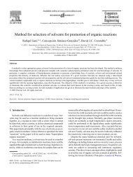
ICAS-PAT manual for Design of process monitoring and ... - CAPEC
ICAS-PAT manual for Design of process monitoring and ... - CAPEC
ICAS-PAT manual for Design of process monitoring and ... - CAPEC

Create successful ePaper yourself
Turn your PDF publications into a flip-book with our unique Google optimized e-Paper software.
<strong>ICAS</strong>-<strong>PAT</strong> <strong>manual</strong><br />
<strong>for</strong><br />
<strong>Design</strong> <strong>of</strong> <strong>process</strong> <strong>monitoring</strong> <strong>and</strong> analysis systems<br />
(<strong>PAT</strong> systems)<br />
Ravendra Singh, Krist V. Gernaey, Rafiqul Gani<br />
June 2009<br />
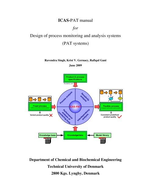
Product & <strong>process</strong><br />
specifications<br />
Provided by user<br />
Fixed <strong>process</strong><br />
(without <strong>monitoring</strong> & control system)<br />
Variant product quality<br />
Process analysis<br />
Per<strong>for</strong>mance<br />
analysis <strong>of</strong><br />
<strong>monitoring</strong> tools<br />
<strong>ICAS</strong>-<strong>PAT</strong><br />
Sensitivity<br />
analysis<br />
Interdependency<br />
analysis<br />
C<br />
Consistent predefined<br />
product quality<br />
M<br />
Flexible <strong>process</strong><br />
(<strong>Design</strong>ed <strong>monitoring</strong> & control system)<br />
Knowledge base<br />
Knowledge/data<br />
Model library<br />
Department <strong>of</strong> Chemical <strong>and</strong> Biochemical Engineering<br />
Technical University <strong>of</strong> Denmark<br />
2800 Kgs. Lyngby, Denmark
Contents .................................................................................................................Page no.<br />
1. Introduction................................................................................................................. 2<br />
1.1. Prerequisites........................................................................................................ 2<br />
1.2. Registration <strong>of</strong> COM object................................................................................ 2<br />
1.3. Precheck.............................................................................................................. 2<br />
2. Main interface ............................................................................................................. 2<br />
2.1. Open solved example.......................................................................................... 2<br />
2.2. Find applications <strong>of</strong> <strong>monitoring</strong> tools................................................................. 3<br />
2.3. Retrieve knowledge/data..................................................................................... 4<br />
2.4. Problem specific supporting tools....................................................................... 6<br />
2.4.1. Problem specific knowledge base............................................................... 6<br />
2.4.2. Problem specific model library................................................................... 7<br />
2.4.3. Problem specific interface........................................................................... 7<br />
3. <strong>Design</strong> <strong>of</strong> <strong>process</strong> <strong>monitoring</strong> <strong>and</strong> analysis systems (<strong>PAT</strong> systems).......................... 9<br />
3.1. Product quality specifications (Step 1) ............................................................. 10<br />
3.2. Process specifications (Step 2).......................................................................... 10<br />
3.3. Process analysis (Step 3)................................................................................... 12<br />
3.4. Sensitivity analysis (Step 4).............................................................................. 13<br />
3.5. Interdependency analysis (Step 5) .................................................................... 16<br />
3.6. Per<strong>for</strong>mance analysis <strong>of</strong> <strong>monitoring</strong> tools (Step 6)........................................... 19<br />
3.7. Proposed <strong>process</strong> <strong>monitoring</strong> <strong>and</strong> analysis system (Step 7) ............................. 22<br />
3.8. Validation (Step 8)............................................................................................ 22<br />
3.9. Final <strong>process</strong> <strong>monitoring</strong> & analysis system (Step 9)....................................... 26<br />
4. Data management...................................................................................................... 27<br />
4.1. Save workbook.................................................................................................. 27<br />
4.2. Build report in MS Word .................................................................................. 27<br />
Appendix A: report generated in MS Word...................................................................... 29<br />
1
1. Introduction<br />
1.1. Prerequisites<br />
• <strong>PAT</strong>_Prototype.xls, user interface, as an excel file<br />
• knowledge base.xls, knowledge base, as an excel file<br />
• Model library containing the MoT files<br />
• MoT_Model_Interface.xls, MoT excel interface, as an excel file<br />
• Installed <strong>ICAS</strong> in the computer<br />
1.2. Registration <strong>of</strong> COM object<br />
Double click on the bat file named, RegCOMMoT.bat in the bin folder:<br />
C:\<strong>CAPEC</strong>\<strong>ICAS</strong>\bin<br />
1.3. Precheck<br />
Make sure that macros are allowed in the excel file. If this is not the case, the following<br />
steps are needed to allow the use <strong>of</strong> macros in excel:<br />
• On the Tools menu, click Options.<br />
• Click the Security tab.<br />
• Under Macro Security, click Macro Security.<br />
• Click the Security Level tab, <strong>and</strong> then select the medium security level.<br />
2. Main interface<br />
Open the file, <strong>PAT</strong>_Prototype.xls, <strong>and</strong> allow the macros to run. The main interface <strong>of</strong><br />
<strong>ICAS</strong>-<strong>PAT</strong> is shown in Figure 1. Different features <strong>of</strong> <strong>ICAS</strong>-<strong>PAT</strong> are described as<br />
follows:<br />
2.1. Open solved example<br />
To load a previously solved example click on the comm<strong>and</strong> button, “Open solved<br />
example”, (see Figure 1, top, right) <strong>and</strong> follow the instructions. Solved examples are<br />
saved in the folder <strong>PAT</strong>\result.<br />
2
Figure 1: Main interface <strong>of</strong> <strong>ICAS</strong>-<strong>PAT</strong><br />
2.2. Find applications <strong>of</strong> <strong>monitoring</strong> tools<br />
Click on comm<strong>and</strong> button, “Find applications <strong>of</strong> <strong>monitoring</strong> tools” (see Figure 1, top,<br />
right) to find the applications <strong>of</strong> <strong>monitoring</strong> tools. This action will open a new window as<br />
shown in figure 2. The following steps need to be taken to find the applications <strong>of</strong><br />
<strong>monitoring</strong> tools:<br />
2.2.1 Write the path <strong>of</strong> the directory containing the knowledge base (e.g.<br />
D:/<strong>PAT</strong>/knowledge base.xls) in the provided text box (the browse option can be<br />
used to search the file <strong>and</strong> copy the directory) <strong>and</strong> click on the comm<strong>and</strong> button,<br />
“Activate knowledge base”.<br />
2.2.2 Click on the comm<strong>and</strong> button, “Type/select <strong>monitoring</strong> technique”, <strong>and</strong> select a<br />
<strong>monitoring</strong> technique from the adjacent drop-down list.<br />
2.2.3 Click on the comm<strong>and</strong> button, “Select <strong>monitoring</strong> tools”, <strong>and</strong> select <strong>monitoring</strong><br />
tools from the adjacent drop-down list (note that, multiple selections are possible).<br />
2.2.4 Click on the comm<strong>and</strong> button, “Find applications”, to list the applications <strong>of</strong><br />
selected <strong>monitoring</strong> tools. Result will be listed in the same window as shown in<br />
figure 2 (all applications are not shown in the figure because <strong>of</strong> space limitations).<br />
2.2.5 Click on the comm<strong>and</strong> button, “Main interface”, to return to main interface.<br />
3
Figure 2: Find applications <strong>of</strong> <strong>monitoring</strong> tools, user interface (left) with a part <strong>of</strong> result (right)<br />
2.3. Retrieve knowledge/data<br />
Click on comm<strong>and</strong> button, “Retrieve the knowledge/data” (see Figure 1, top, right) to<br />
access the direct search engine. This action will open a new window as shown in Figure<br />
3. The following steps need to be taken to search the knowledge/data:<br />
2.3.1. Write the path <strong>of</strong> the directory containing the knowledge base (e.g.<br />
D:/<strong>PAT</strong>/knowledge base.xls) in the provided text box (the browse option (not<br />
shown in figure) can be used to search the file <strong>and</strong> copy the directory) <strong>and</strong> click on<br />
the comm<strong>and</strong> button, “Load knowledge base”.<br />
2.3.2. Click on the comm<strong>and</strong> button, “Select <strong>process</strong>”, <strong>and</strong> select a <strong>process</strong> from the<br />
adjacent drop-down list.<br />
2.3.3. Click on the comm<strong>and</strong> button, “Select <strong>process</strong> points”, <strong>and</strong> select <strong>process</strong> points<br />
from the adjacent list box (note that, multiple selections are possible). There are 3<br />
additional options (‘Select all’, ‘Not found’ <strong>and</strong> ‘Do not know’) that can be<br />
selected if needed.<br />
4
2.3.4. Tick the box “Actuator c<strong>and</strong>idates” (see Figure 3, left), if actuator c<strong>and</strong>idates<br />
also need to be retrieved.<br />
2.3.5. Click on the comm<strong>and</strong> button, “Select <strong>process</strong> variables”, this action will retrieve<br />
the <strong>process</strong> knowledge as shown in Figure 3 (see result selection). If the user is<br />
only interested in retrieving <strong>process</strong> knowledge then there is no need to proceed<br />
further, but if the user wants to retrieve the knowledge on measurement methods<br />
<strong>and</strong> tools also then the next steps need to be followed as well.<br />
2.3.6. Select <strong>process</strong> variables from the list box (adjacent to comm<strong>and</strong> button, “Select<br />
<strong>process</strong> variables”) <strong>and</strong> also select the corresponding variable type from the list<br />
box just below the list box containing the <strong>process</strong> variables.<br />
2.3.7. Click on the comm<strong>and</strong> button, “Select <strong>monitoring</strong> techniques”, <strong>and</strong> select<br />
<strong>monitoring</strong> techniques from the adjacent list box (note that, multiple selections are<br />
possible).<br />
2.3.8. Click on the comm<strong>and</strong> button, “Select <strong>monitoring</strong> tools”, <strong>and</strong> select <strong>monitoring</strong><br />
tools from the adjacent list box (note that, multiple selections are possible).<br />
2.3.9. Click on the comm<strong>and</strong> button, “Select specifications”, <strong>and</strong> select specifications<br />
from the adjacent list box (note that, multiple selections are possible).<br />
2.3.10. Tick the box “Suppliers” (see Figure 3, bottom, left), if in<strong>for</strong>mation on<br />
equipment suppliers also needs to be retrieved.<br />
2.3.11. Click on the comm<strong>and</strong> button, “Search specifications &/or suppliers <strong>of</strong><br />
<strong>monitoring</strong> tools”, to retrieve the <strong>process</strong> knowledge <strong>and</strong> knowledge on<br />
measurement methods <strong>and</strong> tools.<br />
2.3.12. Click on the comm<strong>and</strong> button, “Main interface”, to return to the main interface.<br />
5
Figure 3: Knowledge/data retrieval system, user interface (left) with example <strong>of</strong> a result on the right<br />
(only <strong>process</strong> knowledge is shown)<br />
2.4. Problem specific supporting tools<br />
For new problems, the problem specific supporting tools (knowledge base & model<br />
library) need to be created first be<strong>for</strong>e the problem specific interface can be accessed,<br />
while <strong>for</strong> existing problems, the user can move directly to the problem specific interface<br />
(see Figure 1) <strong>and</strong> can go through each design step.<br />
2.4.1. Problem specific knowledge base<br />
The following steps need to be taken to create the problem specific knowledge base (see<br />
Figure 1, left):<br />
• Write the path <strong>of</strong> the directory containing the knowledge base (e.g.<br />
D:/<strong>PAT</strong>/knowledge base.xls) in the provided text box (the browse option can be used<br />
to search the file <strong>and</strong> copy the directory) <strong>and</strong> click on the comm<strong>and</strong> button, “Load<br />
knowledge base”.<br />
• Click on the comm<strong>and</strong> button, “Select <strong>process</strong>”, <strong>and</strong> select a <strong>process</strong> from the<br />
adjacent drop-down list.<br />
6
• Click on the comm<strong>and</strong> button, “Select <strong>process</strong> points”, <strong>and</strong> select <strong>process</strong> points from<br />
the adjacent list box (note that, multiple selections are possible).<br />
• Click on the comm<strong>and</strong> button, “Problem specific knowledge base”, to create a<br />
problem specific knowledge base.<br />
2.4.2. Problem specific model library<br />
The following steps need to be taken to create the problem specific model library (see<br />
Figure 1, left, bottom):<br />
• Write the path <strong>of</strong> the directory containing the model library (e.g. D:/<strong>PAT</strong>/model<br />
library.xls) in the provided text box (the browse option can be used to search the file<br />
<strong>and</strong> copy the directory) <strong>and</strong> click on the comm<strong>and</strong> button, “Load model library”.<br />
• Select the <strong>process</strong> models from the left list box <strong>and</strong> click on the comm<strong>and</strong> button,<br />
“Add to problem specific model library”, to add the selected <strong>process</strong> model to the<br />
right list box. This action will open the corresponding <strong>process</strong> model <strong>and</strong> the user<br />
needs to save it in a folder named ‘problem specific model library’.<br />
After creating the problem specific supporting tools, Click on the comm<strong>and</strong> button,<br />
“Problem specific interface”, to proceed with the design <strong>of</strong> a <strong>PAT</strong> system.<br />
2.4.3. Problem specific interface<br />
Click on the comm<strong>and</strong> button, “Problem specific interface”, <strong>for</strong> design <strong>of</strong> <strong>PAT</strong> systems.<br />
This action will open a new window containing all the design steps as shown in Figure 4.<br />
Each design step needs to be followed sequentially in order to get the final <strong>PAT</strong> system.<br />
As described in section 3 <strong>of</strong> this <strong>manual</strong>, each design step consists <strong>of</strong> a separate window<br />
through which the input in<strong>for</strong>mation can be provided <strong>and</strong> the output in<strong>for</strong>mation can be<br />
accessed.<br />
7
Figure 4: Problem specific interface (steps <strong>for</strong> design <strong>of</strong> a <strong>PAT</strong> system)<br />
8
3. <strong>Design</strong> <strong>of</strong> <strong>process</strong> <strong>monitoring</strong> <strong>and</strong> analysis systems (<strong>PAT</strong> systems)<br />
The application <strong>of</strong> <strong>ICAS</strong>-<strong>PAT</strong> <strong>for</strong> design <strong>of</strong> a <strong>PAT</strong> system is demonstrated in this <strong>manual</strong><br />
through a fermentation <strong>process</strong> case study. The flowsheet <strong>of</strong> the fermentation <strong>process</strong> is<br />
shown in Figure 5.<br />
Figure 5: Fermentation <strong>process</strong> flowsheet<br />
9
3.1. Product quality specifications (Step 1)<br />
The following steps need to be taken in this phase <strong>of</strong> the design procedure (see Figure<br />
6):<br />
3.1.1. Click on the comm<strong>and</strong> button “1. Product quality specifications”<br />
3.1.2. Write the number <strong>of</strong> products in the allocated place (cell C5 <strong>of</strong> the spreadsheet).<br />
3.1.3. Click on the comm<strong>and</strong> button, “Next” <strong>and</strong> write the name <strong>of</strong> the products in the<br />
allocated place (starting from cell C6 <strong>of</strong> the spreadsheet).<br />
3.1.4. Click on the comm<strong>and</strong> button, “List the specifications” <strong>and</strong> type the<br />
specifications <strong>of</strong> each product in the allocated place.<br />
After completing Step 1, click on the comm<strong>and</strong> button “2. Process specifications” to<br />
proceed to the next step <strong>of</strong> the design procedure.<br />
Figure 6: Product quality specifications<br />
3.2. Process specifications (Step 2)<br />
The following steps need to be taken in this phase <strong>of</strong> the design procedure (see Figure<br />
7):<br />
3.2.1. Write the path <strong>of</strong> the directory containing the knowledge base (e.g.<br />
D:/<strong>PAT</strong>/knowledge base.xls) in the provided text box (the browse option can be<br />
used to search the file <strong>and</strong> copy the directory <strong>of</strong> file) <strong>and</strong> click on the comm<strong>and</strong><br />
button, “Load Knowledge base”.<br />
3.2.2. Click on the comm<strong>and</strong> button, “Select the <strong>process</strong>” <strong>and</strong> select the <strong>process</strong> from<br />
the drop-down list <strong>for</strong> which the <strong>PAT</strong> system has to be designed. Select the option<br />
‘Not found’, if the <strong>process</strong> is not found in the list.<br />
10
3.2.3. Click on the comm<strong>and</strong> button, “Next” <strong>and</strong> write the number <strong>of</strong> equipments used in<br />
the <strong>process</strong>, in the spreadsheet cell that is reserved <strong>for</strong> that in<strong>for</strong>mation. Write the<br />
number <strong>of</strong> raw materials used in the <strong>process</strong> in the appropriate place <strong>and</strong> write the<br />
name <strong>of</strong> each raw material under the heading, Raw material list.<br />
3.2.4. Click on the comm<strong>and</strong> button, Select equipments <strong>and</strong> select the equipments from<br />
the drop-down list. Select the option ‘Not found’ <strong>for</strong> further instruction, if any<br />
equipment is not found in the list. The selected number <strong>of</strong> equipments must be<br />
equal to the number <strong>of</strong> equipments specified in step 3.2.3.<br />
3.2.5. Generate flowsheet: The open loop <strong>process</strong> flowsheet can be generated through<br />
<strong>ICAS</strong>-<strong>PAT</strong> (see Figure 7, top, right corner). The following steps need to be taken<br />
to generate the simplified <strong>process</strong> flowsheet:<br />
• Click on comm<strong>and</strong> button, “Provide input/output in<strong>for</strong>mation” <strong>and</strong> provide the<br />
input/output in<strong>for</strong>mation <strong>of</strong> the <strong>process</strong> as shown in Figure 8. Type the name <strong>of</strong> the<br />
equipments, the corresponding operations, <strong>and</strong> the input/output streams under the<br />
specified headings. Leave blanks, if some options are not applicable.<br />
• Click on comm<strong>and</strong> button, “Draw flowsheet” to generate the flowsheet, as shown in<br />
Figure 9.<br />
After completing Step 2, click on the comm<strong>and</strong> button “3. Process analysis” to go to the<br />
next step <strong>of</strong> the procedure.<br />
Figure 7: Process specifications<br />
11
Equipments Operations Main stream in Side stream in Main stream out Side stream out<br />
Mixing tank Mixing Mixed media Water Mixed media<br />
Media<br />
Heat sterilizer Heat sterilization Sterilized media<br />
Fermentor Fermentation Ammonia Biomass Air<br />
Air<br />
Figure 8: Input/output in<strong>for</strong>mation to draw the flowsheet (fermentation <strong>process</strong>)<br />
Water<br />
Mixing tank<br />
Heat sterilizer<br />
Ammonia<br />
Fermentor<br />
Air<br />
Media<br />
Air<br />
Mixing<br />
Heat sterilization<br />
Fermentation<br />
Biomass<br />
Figure 9: Generated flowsheet (fermentation <strong>process</strong>)<br />
3.3. Process analysis (Step 3)<br />
The following steps need to be taken in this phase <strong>of</strong> the design procedure (see Figure<br />
10):<br />
3.3.1. Click on the comm<strong>and</strong> button, “List the <strong>process</strong> points”.<br />
3.3.2. Write the path <strong>of</strong> the directory containing the knowledge base (e.g.<br />
D:/<strong>PAT</strong>/knowledge base.xls) in the provided list box (the browse option can be<br />
used to search the file <strong>and</strong> copy the directory <strong>of</strong> file) <strong>and</strong> click on the comm<strong>and</strong><br />
button, “List the variables related to each <strong>process</strong> point”.<br />
3.3.3. Process variables are user specific. Thus, the user has to check each listed <strong>process</strong><br />
variable thoroughly, <strong>and</strong> modify the list if needed (remove the unnecessary<br />
variables from the list, or add extra variables if required. Note that no empty<br />
(blank) cells should be left between the variables).<br />
3.3.4. Write the values <strong>of</strong> the lower <strong>and</strong> the upper operational limit, <strong>and</strong> add the unit <strong>of</strong><br />
each listed variable in the place reserved <strong>for</strong> that in<strong>for</strong>mation. The user can refer to<br />
a data sheet (data_sheet.xls) to access this in<strong>for</strong>mation.<br />
After completing Step 3, click on the comm<strong>and</strong> button “4. Sensitivity analysis” to<br />
proceed to the next step <strong>of</strong> the design procedure.<br />
12
Figure 10: Process analysis<br />
3.4. Sensitivity analysis (Step 4)<br />
If <strong>process</strong> operational data are already available (either from experiments or based on a<br />
simulation), then load the saved data by clicking on the comm<strong>and</strong> button, “Load the<br />
saved data (open loop)” (see Figure 11), <strong>and</strong> skip the steps 4.2 to 4.3. If the <strong>process</strong><br />
operational data are not available then the following steps need to be taken (see Figure<br />
11):<br />
3.4.1. Click on the comm<strong>and</strong> button, “Select a <strong>process</strong> point”, <strong>and</strong> select a <strong>process</strong> point<br />
from the adjacent drop-down list. Click on the comm<strong>and</strong> button, “Select the<br />
operational objective”, <strong>and</strong> select the operational objective from the adjacent<br />
drop-down list. Type the operational objective, if the desired objective is not found<br />
in the list (the operational objective is the objective that the user wants to achieve in<br />
the selected operation).<br />
3.4.2. Write the path <strong>of</strong> the directory containing the file MoT_Model_Interface.xls (e.g.<br />
D:/<strong>PAT</strong>/MoT_Model_Interface.xls) in the provided list box (the browse option can<br />
be used to search the file <strong>and</strong> copy the directory <strong>of</strong> file). Then click on the<br />
comm<strong>and</strong> button, “Solve the model”. This step will direct the user to a new excel<br />
workbook named, MoT_Model_Interface.xls (see Figure 12):<br />
• Click on the comm<strong>and</strong> button, “Load MoT Model”. This step will open a<br />
browsing window (see Figure 12, right).<br />
• Browse the model (models are saved in the folder <strong>PAT</strong>/Model library) <strong>and</strong> load<br />
the model details in to the excel sheet (see Figure 12, left).<br />
13
• Click on the comm<strong>and</strong> button, file name.mot to solve the model. The final value<br />
<strong>of</strong> the variables are shown in Figure 12 (highlighted with red color) <strong>and</strong> the<br />
whole dynamic simulated data is stored in a different file.<br />
• Activate the workbook (maximize the window), <strong>PAT</strong>_Prototype.xls<br />
3.4.3. Click on the comm<strong>and</strong> button, “Load simulation result” .<br />
3.4.4. Click on the comm<strong>and</strong> button, “Select variable”. To analyze the objective<br />
function, select the X axis (independent) variable (usually, ‘Time’ should be<br />
selected as a X axis variable) <strong>and</strong> Y axis variable (objective function) from the<br />
drop-down list <strong>and</strong> select the corresponding symbol <strong>of</strong> the selected variable<br />
(objective function) from the drop-down list.<br />
3.4.5. Click on the comm<strong>and</strong> button, “Operational limits <strong>of</strong> selected variable”.<br />
3.4.6. To plot the selected variable (operational objective), click on the comm<strong>and</strong> button,<br />
“Plot”. If the operational objective is not achieved (if it violates the limits), then<br />
the next step in the procedure needs to be followed.<br />
3.4.7. Select a <strong>process</strong> variable <strong>and</strong> corresponding symbol from the drop-down list<br />
(similarly as mentioned in step 4.4), specify operational limits (similarly as<br />
mentioned in the step 4.5) <strong>and</strong> plot the result (see Figure 11 <strong>for</strong> an example <strong>of</strong> the<br />
result <strong>of</strong> this operation).<br />
3.4.8. Click on the comm<strong>and</strong> button, “Analyze the selected variable”. This comm<strong>and</strong><br />
will open a message box. Select ‘Yes’ if the variable violates the operational limit<br />
<strong>and</strong> ‘No’ if it is within the operational limit.<br />
3.4.9. Repeat steps 4.7 <strong>and</strong> 4.8 <strong>for</strong> each <strong>process</strong> variable involved with the selected<br />
<strong>process</strong> point. The result <strong>of</strong> this step is stored in the result section (see Figure 11,<br />
right).<br />
Open loop simulation data management<br />
• To save the open loop simulation data, write the path <strong>of</strong> the directory where the<br />
data has to be saved <strong>and</strong> click on the comm<strong>and</strong> button, “Save the open loop<br />
simulation data” (see Figure 11).<br />
• To load the saved data click on the comm<strong>and</strong> button, “Load the saved data (open<br />
loop)” (see Figure 11). Follow the steps 4.4 to 4.9 <strong>for</strong> sensitivity analysis based on<br />
the saved data.<br />
14
After completing step 4 <strong>for</strong> the selected <strong>process</strong> point, click on the comm<strong>and</strong> button “5.<br />
Interdependency analysis” to proceed to the next step <strong>of</strong> the design procedure.<br />
Figure 11: Sensitivity analysis<br />
15
Figure 12: MoT model interface<br />
3.5. Interdependency analysis (Step 5)<br />
The following steps need to be taken in this phase <strong>of</strong> the design procedure (see Figure<br />
13a):<br />
3.5.1. Click on the comm<strong>and</strong> button, “Select a <strong>process</strong> point”, <strong>and</strong> select a <strong>process</strong> point<br />
from the adjacent drop-down list (note that the <strong>process</strong> point selected in this step<br />
must be identical to the <strong>process</strong> point selected in Step 4).<br />
3.5.2. Selection <strong>of</strong> actuator c<strong>and</strong>idates:<br />
3.5.2.1. Click on the comm<strong>and</strong> button, “Select a critical <strong>process</strong> variable”, <strong>and</strong> select a<br />
critical <strong>process</strong> variable (or select all) from the adjacent drop-down list.<br />
3.5.2.2. Click on the comm<strong>and</strong> button, “List the actuator c<strong>and</strong>idates”. This comm<strong>and</strong><br />
will list the actuator c<strong>and</strong>idates <strong>for</strong> the selected critical <strong>process</strong> variable. Note<br />
that this list provides the actuator c<strong>and</strong>idates to the user based on data available<br />
16
in the knowledge base. However, the user can modify this list according to<br />
his/her needs.<br />
3.5.2.3. Click on the comm<strong>and</strong> button, “Select critical variables”, <strong>and</strong> select critical<br />
<strong>process</strong> variables from the list box, containing unknown variables (the effect <strong>of</strong><br />
actuator c<strong>and</strong>idates on these variables has to be studied).<br />
3.5.2.4. Click on the comm<strong>and</strong> button, “Select actuator c<strong>and</strong>idates”, <strong>and</strong> select actuator<br />
c<strong>and</strong>idates from the list box containing known variables <strong>and</strong> parameters.<br />
3.5.3. Perturbation: If the interdependency analysis data are already available (either<br />
from experiments or based on a simulation) then load the saved data by clicking on<br />
the comm<strong>and</strong> button, “Load the saved data (interdependency analysis)” (see<br />
Figure 13a, left) <strong>and</strong> skip the step 3.5.3.1:<br />
3.5.3.1. Perturbation setup: type the values <strong>of</strong> the lower <strong>and</strong> upper bound as well as the<br />
step <strong>for</strong> perturbing the actuator c<strong>and</strong>idates (an example is given in Figure 13b,<br />
where the lower bound <strong>of</strong> the perturbation corresponds to -15% <strong>and</strong> the upper<br />
bound corresponds to +15%, whereas the step size <strong>for</strong> modifying the perturbation<br />
is 5%). Click on the comm<strong>and</strong> button, “Per<strong>for</strong>med interdependency analysis”.<br />
This comm<strong>and</strong> will perturb the actuator c<strong>and</strong>idates <strong>and</strong> record the effect <strong>of</strong> the<br />
perturbation on selected critical <strong>process</strong> variables.<br />
3.5.3.2. Click on the comm<strong>and</strong> button, “Select critical variable”, <strong>and</strong> select the variable<br />
from the drop-down list <strong>for</strong> which you want to see the result. Make sure that the<br />
critical <strong>process</strong> variable selected in step 3.5.2.1 is the same as the one selected in<br />
this step. If this is not the case then select the same variable in step 3.5.2.1 also.<br />
3.5.3.3. Click on the comm<strong>and</strong> button, “Result” , to see the result (in table <strong>for</strong>m). To plot<br />
the result click on the comm<strong>and</strong> button, “Plot” <strong>and</strong> analyze the result to identify<br />
the most sensitive actuator c<strong>and</strong>idate (see Figure 13b).<br />
3.5.4. Click on the comm<strong>and</strong> button, “Select actuator”, <strong>and</strong> select the most sensitive<br />
actuator c<strong>and</strong>idate as the final actuator <strong>for</strong> the selected variable.<br />
3.5.5. Repeat steps 3.5.2 – 3.5.4 <strong>for</strong> each critical <strong>process</strong> variable involved with the<br />
selected critical <strong>process</strong> point. Result <strong>of</strong> this step is stored in the result section (see<br />
Figure 13b, right).<br />
17
Data management (interdependency analysis)<br />
• To save the interdependency analysis data, write the path <strong>of</strong> the directory where<br />
the data has to be saved <strong>and</strong> click on the comm<strong>and</strong> button, “Save simulation data<br />
(interdependency analysis)” (see Figure 13a).<br />
• To load the saved data click on the comm<strong>and</strong> button, “Load the saved data<br />
(interdependency analysis)” (see Figure 13a).<br />
After completing step 5 <strong>for</strong> the selected <strong>process</strong> point, click on the comm<strong>and</strong> button “6.<br />
Per<strong>for</strong>mance analysis <strong>of</strong> <strong>monitoring</strong> tools” to proceed to the next step <strong>of</strong> the design<br />
procedure.<br />
Figure 13a: Interdependency analysis<br />
18
Figure 13b: Interdependency analysis<br />
3.6. Per<strong>for</strong>mance analysis <strong>of</strong> <strong>monitoring</strong> tools (Step 6)<br />
The following steps need to be taken in this phase <strong>of</strong> the design procedure (see Figure<br />
14):<br />
3.6.1. Click on the comm<strong>and</strong> button, “Select a <strong>process</strong> point”, <strong>and</strong> select a <strong>process</strong><br />
point from the adjacent drop-down list (note that the <strong>process</strong> point selected in this<br />
step must be identical to the <strong>process</strong> point selected in Step 4).<br />
3.6.2. Click on the comm<strong>and</strong> button, “Select a critical <strong>process</strong> variable”, <strong>and</strong> select a<br />
critical <strong>process</strong> variable (or select all) from the adjacent drop-down list (see<br />
Figure 14). Follow steps 3.6.2.1-3.6.2.2:<br />
3.6.2.1. Tick on the per<strong>for</strong>mance criteria <strong>of</strong> the <strong>monitoring</strong> tools that you want to list (see<br />
Figure 14)<br />
3.6.2.2. Click on the comm<strong>and</strong> button, “List the <strong>monitoring</strong> tools” (see Figure 14). This<br />
comm<strong>and</strong> will generate a table containing the monitored variable, <strong>monitoring</strong><br />
techniques, <strong>monitoring</strong> tools <strong>and</strong> corresponding specifications. The user can<br />
modify this table according to his/her needs.<br />
19
3.6.3. Grading <strong>of</strong> <strong>monitoring</strong> tools: select the variable from the drop-down list (or select<br />
all) <strong>and</strong> Click on the comm<strong>and</strong> button, “Grade the <strong>monitoring</strong> tools” (see Figure<br />
14). This comm<strong>and</strong> will assign a grade in the range 5 to 1 to the top 5 <strong>monitoring</strong><br />
tools in the category <strong>of</strong> the selected specification, whereas the rest <strong>of</strong> the tools<br />
will get the grade zero. Note also that in case the value <strong>of</strong> any specification <strong>of</strong> a<br />
<strong>monitoring</strong> tool is not assigned (e.g. because no in<strong>for</strong>mation was available in the<br />
literature, then that <strong>monitoring</strong> tool will automatically get the grade zero (see<br />
Figure 15).<br />
3.6.4. Selection <strong>of</strong> <strong>monitoring</strong> tool: select a critical <strong>process</strong> variable (or select all) from<br />
the drop-down list <strong>and</strong> follow steps 6.4.1-6.4.2 (see Figure 14):<br />
3.6.4.1.Click on the comm<strong>and</strong> button, “Select per<strong>for</strong>mance criteria” <strong>and</strong> select the<br />
criteria on the basis <strong>of</strong> which the <strong>monitoring</strong> tool has to be selected. Note that the<br />
choice <strong>of</strong> the final selected <strong>monitoring</strong> tools will depend on the selected<br />
per<strong>for</strong>mance criteria!<br />
3.6.4.2.Click on the comm<strong>and</strong> button, “Select <strong>monitoring</strong> tool”.<br />
3.6.5. Repeat step 3.6.2-3.6.4 <strong>for</strong> each critical <strong>process</strong> variable involved with the<br />
selected critical <strong>process</strong> point. Result <strong>of</strong> this step is stored in result section (not<br />
shown).<br />
After completing the step 6 <strong>for</strong> the selected <strong>process</strong> point, click on the comm<strong>and</strong> button<br />
“7. Proposed <strong>process</strong> <strong>monitoring</strong> <strong>and</strong> analysis system” to proceed to the next step <strong>of</strong><br />
the design procedure.<br />
20
Figure 14: Per<strong>for</strong>mance analysis <strong>of</strong> <strong>monitoring</strong> tools<br />
Figure 15: Grading <strong>of</strong> <strong>monitoring</strong> tools<br />
21
3.7. Proposed <strong>process</strong> <strong>monitoring</strong> <strong>and</strong> analysis system (Step 7)<br />
Click on the comm<strong>and</strong> button, “Propose a <strong>process</strong> <strong>monitoring</strong> <strong>and</strong> analysis system”.<br />
This comm<strong>and</strong> creates a table containing the critical <strong>process</strong> points, the critical <strong>process</strong><br />
variables, the selected actuators, <strong>monitoring</strong> techniques <strong>and</strong> <strong>monitoring</strong> tools (see Figure<br />
16).<br />
After completing step 7 <strong>for</strong> the selected <strong>process</strong> point, click on the comm<strong>and</strong> button “8.<br />
Validation” to proceed to the next step <strong>of</strong> the design procedure.<br />
Figure 16: Proposed <strong>process</strong> <strong>monitoring</strong> <strong>and</strong> analysis system<br />
3.8. Validation (Step 8)<br />
If the <strong>process</strong> operational data (closed loop) are already available (either from<br />
experiments or based on a simulation), then load the saved data by clicking on the<br />
comm<strong>and</strong> button, “Load the saved data (closed loop)” (see Figure 17, bottom left) <strong>and</strong><br />
skip the steps 3.8.2 to 3.8.5. If the <strong>process</strong> operational data are not available then the<br />
following steps need to be taken in this phase <strong>of</strong> the design procedure (see Figure 17):<br />
3.8.1. Click on the comm<strong>and</strong> button, “Select a <strong>process</strong> point”, <strong>and</strong> select a <strong>process</strong><br />
point from the adjacent drop-down list (note that the <strong>process</strong> point selected in this<br />
step must be identical to the <strong>process</strong> point selected in step 4).<br />
3.8.2. Click on the comm<strong>and</strong> button, “Select the control variable” <strong>and</strong> select the<br />
control variable from the drop-down list.<br />
3.8.3. Click on the comm<strong>and</strong> button, “Select the actuator” <strong>and</strong> select the actuator from<br />
the drop-down list. Follow steps 3.8.3.1-3.8.3.3 <strong>for</strong> setting <strong>of</strong> controller<br />
parameters.<br />
22
3.8.3.1. Click on the comm<strong>and</strong> button, “Select the control parameters” <strong>and</strong> select the<br />
controller parameters from the drop-down list. A message box, asking whether<br />
the user wants to select the default value <strong>of</strong> the controller parameters will<br />
appear, on selection <strong>of</strong> controller parameters. The value <strong>of</strong> controller parameters<br />
will be assigned automatically, if the user will accept the default option.<br />
Otherwise the user needs to type the value <strong>of</strong> the controller parameters in the<br />
provided text box. Note that only a PI & on-<strong>of</strong>f controller is implemented at this<br />
moment, so the derivative controller constant K D is always set equal to zero. For<br />
on-<strong>of</strong>f controller K switch =0 means open loop <strong>and</strong> K switch =1 means closed loop.<br />
3.8.3.2. Click on the comm<strong>and</strong> button, “Activate the loop”. Similarly the comm<strong>and</strong><br />
button “Deactivate the loop” can be used to deactivate the unwanted control<br />
loop.<br />
3.8.3.3. Repeat the above steps 3.8.2-3.8.3 <strong>for</strong> all control loops (as a rule <strong>of</strong> thumb, the<br />
number <strong>of</strong> control loops should be equal to the number <strong>of</strong> critical <strong>process</strong><br />
variables).<br />
3.8.4. Click on the comm<strong>and</strong> button, “Solve the closed loop model”.<br />
3.8.5. Click on the comm<strong>and</strong> button, “Load simulation result”.<br />
3.8.6. Click on the comm<strong>and</strong> button, “Select variable” <strong>and</strong> select a critical <strong>process</strong><br />
variable that you want to plot. Also select the corresponding set point <strong>and</strong><br />
actuator.<br />
3.8.7. Click on the comm<strong>and</strong> button, “Operational limit <strong>of</strong> selected variable”. This<br />
comm<strong>and</strong> will provide the lower <strong>and</strong> upper limit <strong>of</strong> the critical <strong>process</strong> variable<br />
(note that the user can modify this limit). The user can also specify the limit <strong>of</strong> the<br />
actuator in the cells allocated <strong>for</strong> that in<strong>for</strong>mation.<br />
3.8.8. To see the result, click on the comm<strong>and</strong> button, “Plot”. The closed loop response<br />
<strong>of</strong> two variables (dissolved oxygen <strong>and</strong> pH) are shown in Figure 18 as an<br />
example. Actuator plots are not shown.<br />
3.8.9. To analyze the variable, click on the comm<strong>and</strong> button, “Analyze the selected<br />
variable” <strong>and</strong> follow the instructions. If the set point <strong>of</strong> the controlled variable is<br />
achieved <strong>and</strong> the actuator is within the limit, then this control variable-actuator<br />
pair can be selected <strong>for</strong> the final design. As shown in Figure 18 dissolved oxygen<br />
23
<strong>and</strong> pH are within the limits <strong>and</strong> corresponding actuators are also within the limits<br />
(not shown).<br />
3.8.10. Repeat steps 3.8.6-3.8.9 <strong>for</strong> all critical <strong>process</strong> variables involved with the<br />
selected critical <strong>process</strong> point.<br />
3.8.11. Sensitivity verification: to analyze the relative sensitivity <strong>of</strong> the controlled<br />
variable follow the following steps (see Figure 19):<br />
3.8.11.1. Click on the comm<strong>and</strong> button, “Select objective function” <strong>and</strong> select the<br />
operational objective from the adjacent list box (<strong>for</strong> instance cell growth rate<br />
(mue) is selected as the operational objective in fermentation <strong>process</strong>).<br />
3.8.11.2. Click on the comm<strong>and</strong> button, “Select control variable (set point)” <strong>and</strong> select<br />
the controlled variables (set points) from the adjacent list box (<strong>for</strong> instance<br />
dissolved oxygen (DO_set), pH, pH_set, <strong>and</strong> temperature (T_set) are selected as<br />
the controlled variables).<br />
3.8.11.3. Perturbation setup: type the values <strong>of</strong> the lower <strong>and</strong> upper bound as well as the<br />
step <strong>for</strong> perturbing the control variables (set points) (an example is given in<br />
Figure 19, where the lower bound <strong>of</strong> the perturbation corresponds to -4% <strong>and</strong><br />
the upper bound corresponds to +4%, whereas the step size <strong>for</strong> modifying the<br />
perturbation is 2%).<br />
3.8.11.4. Click on the comm<strong>and</strong> button, “Sensitivity verification”. This comm<strong>and</strong> will<br />
perturb the controlled variables (set points) <strong>and</strong> record the effect <strong>of</strong> the<br />
perturbation on the objective function.<br />
3.8.11.5. Click on the comm<strong>and</strong> button, “Select objective function”, <strong>and</strong> select the<br />
objective function from the drop-down list.<br />
3.8.11.6. Click on the comm<strong>and</strong> button, “Result” , to see the result (in table <strong>for</strong>m). To<br />
plot the result click on the comm<strong>and</strong> button, “Plot” <strong>and</strong> analyze the result. If the<br />
sensitivity <strong>of</strong> the proposed controlled variable is negligible then it should not be<br />
included in the final list <strong>of</strong> the <strong>PAT</strong> system. Figure 19 shows the relative<br />
sensitivity <strong>of</strong> the cell growth rate (objective function) w.r.t. dissolved oxygen,<br />
pH <strong>and</strong> temperature (controlled variables). The Figure shows that the cell<br />
growth rate is most sensitive <strong>for</strong> dissolved oxygen followed by pH <strong>and</strong><br />
temperature.<br />
24
Closed loop simulation data management<br />
• To save the closed loop simulation data, write the path <strong>of</strong> the directory where the<br />
data has to be saved <strong>and</strong> click on the comm<strong>and</strong> button, “Save the closed loop<br />
simulation data” (see Figure 17).<br />
• To load the saved data click on the comm<strong>and</strong> button, “Load the saved data<br />
(closed loop)” (see Figure 17). Follow the steps 3.8.6 to 3.8.11 <strong>for</strong> validation<br />
based on the saved data.<br />
After completing step 8, click on the comm<strong>and</strong> button “9. Final <strong>process</strong> <strong>monitoring</strong> &<br />
analysis system” to proceed to the next step <strong>of</strong> the design procedure.<br />
Figure 17: Validation<br />
0.008<br />
DO (Dissolved oxygen)<br />
9<br />
pH<br />
0.007<br />
8<br />
O(Kg/m3)<br />
0.006<br />
0.005<br />
Achieved pr<strong>of</strong>ile<br />
Lower limit<br />
0.004<br />
Upper limit<br />
0.003<br />
Set points<br />
0.002<br />
0.001<br />
0<br />
0 3 6 9 12 15 18<br />
Time (hr)<br />
pH<br />
Figure 18: Closed loop response <strong>of</strong> variables<br />
7<br />
6<br />
5<br />
4<br />
Achieved pr<strong>of</strong>ile<br />
3<br />
Lower limit<br />
2<br />
Upper limit<br />
1<br />
Set points<br />
0<br />
0 3 6 9 12 15 18<br />
Time (hr)<br />
25
Figure 19: Sensitivity verification<br />
3.9. Final <strong>process</strong> <strong>monitoring</strong> & analysis system (Step 9)<br />
The following steps need to be taken in this phase <strong>of</strong> the design procedure (see Figure<br />
20):<br />
3.9.1. Click on the comm<strong>and</strong> button, “Process <strong>monitoring</strong> & analysis system”. This<br />
comm<strong>and</strong> will create a table containing the critical <strong>process</strong> points, critical <strong>process</strong><br />
variables, actuators, <strong>monitoring</strong> techniques <strong>and</strong> <strong>monitoring</strong> tools as shown in<br />
Figure 20.<br />
3.9.2. Repeat step 1-8 <strong>for</strong> each <strong>process</strong> point.<br />
3.9.3. Draw flowsheet: follow the following steps to generate a <strong>process</strong> flowsheet with<br />
designed <strong>PAT</strong> system.<br />
• Click on the comm<strong>and</strong> button, “Select specifications”, <strong>and</strong> select the<br />
specifications from the adjacent list box (see Figure 20) that you want to include<br />
in the flowsheet.<br />
• Click on the comm<strong>and</strong> button, “Draw flowsheet”, to draw the flowsheet, as<br />
shown in Figure 21.<br />
26
4. Data management<br />
The Following options are available <strong>for</strong> data management:<br />
4.1. Save workbook<br />
• Write the directory name where you want to save the workbook <strong>and</strong> click on the<br />
comm<strong>and</strong> button, “Save the workbook”.<br />
• Save the result <strong>of</strong> each analysis step: write the name <strong>of</strong> the directory where you<br />
want to save the result <strong>and</strong> click on the comm<strong>and</strong> button, “Save the result”.<br />
4.2. Build report in MS Word<br />
Click on the comm<strong>and</strong> button, “Build report in MS Word” to make a report in MS<br />
Word as given in Appendix A.<br />
Figure 20: Final <strong>process</strong> <strong>monitoring</strong> & analysis system<br />
27
Feed<br />
Mixing tank<br />
Mixing time<br />
Homogeneity<br />
C<br />
RT= 00.002000 s<br />
Pr= 0.100000 nm<br />
Ac= 0.100000 nm<br />
NIR<br />
Stirrer speed<br />
Coolant flow rate<br />
Flow rate <strong>of</strong> NH3<br />
Air flow rate<br />
C<br />
C<br />
Sterilizer<br />
Steam flow rate<br />
Main stream<br />
temperature<br />
C<br />
RT= 150.000000<br />
Pr= 0.003000 oC<br />
Ac= 0.400000 % <strong>of</strong><br />
Thermistor<br />
Fermentor<br />
DO (Dissolved<br />
oxygen)<br />
pH<br />
Temperature<br />
Homogeneity<br />
RT= 1.000000 s<br />
Pr= 0.100000 '%<br />
Ac= 0.100000 % FS<br />
Optical<br />
sensor<br />
RT= 10.000000 s<br />
Pr= 0.003000 pH<br />
Ac= 0.200000 pH<br />
Electroche<br />
mical<br />
Figure 21. Process <strong>monitoring</strong> <strong>and</strong> analysis system <strong>for</strong> the fermentation <strong>process</strong>.<br />
c: controller, Ac: Accuracy, Pr: Precision, RT: response time<br />
C<br />
C<br />
RT= 150.000000<br />
Pr= 0.003000 oC<br />
Ac= 0.400000 % <strong>of</strong><br />
Thermistor<br />
RT= 00.002000 s<br />
Pr= 0.100000 nm<br />
Ac= 0.100000 nm<br />
NIR<br />
Product<br />
28
Appendix A: report generated in MS Word<br />
<strong>Design</strong> <strong>of</strong> <strong>process</strong> <strong>monitoring</strong> <strong>and</strong> analysis system (<strong>PAT</strong> system)<br />
Step1: Product quality specifications<br />
1. Specifications <strong>of</strong> Biomass Value Unit<br />
Composition 2.95 % (w/w)<br />
Concentration 30.00 g/l<br />
2. Specifications <strong>of</strong> Glucose Value Unit<br />
Composition 4.00 % (w/w)<br />
Concentration 40.69 g/l<br />
3. Specifications <strong>of</strong> Salts Value Unit<br />
Composition 0.58 % (w/w)<br />
Concentration 5.93 g/l<br />
4. Specifications <strong>of</strong> Water Value Unit<br />
Composition 92.46 % (w/w)<br />
Concentration 939.44 g/l<br />
Step2: Process specifications<br />
Equipment list<br />
Fermentor<br />
Sterilizer<br />
Mixing tank<br />
Raw material list<br />
Starter culture<br />
Glucose<br />
Salts<br />
Water<br />
Ammonia<br />
Air<br />
Step3: Process analysis<br />
Process points Process variables Lower limit Upper limit Unit<br />
Fermentor DO (Dissolved oxygen) 0.00067 0.007 Kg/m3<br />
Dissolved CO2 0.0005 0.004 Kg/m3<br />
pH 6 7<br />
Temperature 293 310 K<br />
Pressure 1 2 atm<br />
Inlet flow rate <strong>of</strong> air 0 10 m/s<br />
Outlet flow rate <strong>of</strong> air 0 10 m/s<br />
Inlet flow rate <strong>of</strong> NH3 0 10 m/s<br />
Outlet flow rate <strong>of</strong> NH3 0 10 m/s<br />
Substrate concentration 1 180 Kg/m3<br />
Biomass concentration 1 30 Kg/m3<br />
29
Cell mass 30 900 kg<br />
Foaming level 0 0.01 m<br />
Stirrer speed 0 10 rps<br />
Cell growth rate 0.1 0.15 hr-1<br />
Homogeneity 0.7 1 fractional<br />
homogeneous<br />
Sterilizer Steam temperature 120 200 oC<br />
Main stream temperature 120 150 oC<br />
Main stream flow rate 300 700 Kg/hr<br />
Steam flow rate 0 1000 Kg/hr<br />
Sterilization duration 0 7 hour<br />
Mixing tank Stirrer speed 0 36000 rps<br />
Step4: Sensitivity analysis<br />
Mixing time 0 3 hour<br />
Homogeneity 0.95 1 Fractional<br />
homogeneous<br />
Critical <strong>process</strong> points<br />
Mixing tank<br />
Sterilizer<br />
Fermentor<br />
Fermentor<br />
Fermentor<br />
Fermentor<br />
Fermentor<br />
Critical <strong>process</strong> variables<br />
Homogeneity<br />
Main stream temperature<br />
DO (Dissolved oxygen)<br />
pH<br />
Dissolved CO2<br />
Temperature<br />
Homogeneity<br />
Step5: Interdependency analysis<br />
Critical <strong>process</strong> points Critical <strong>process</strong> variables Actuators<br />
Mixing tank Homogeneity Mixing time<br />
Sterilizer Main stream temperature Steam flow rate<br />
Fermentor DO (Dissolved oxygen) Air flow rate<br />
Fermentor pH Flow rate <strong>of</strong> NH3<br />
Fermentor Dissolved CO2 Air flow rate<br />
Fermentor Temperature Coolant flow rate<br />
Fermentor Homogeneity Stirrer speed<br />
Step6: Per<strong>for</strong>mance analysis <strong>of</strong> <strong>monitoring</strong> tools<br />
Critical points Critical variables Monitoring Monitoring tools<br />
techniques<br />
Mixing tank Homogeneity NIR EPP 2000 Fiber Optic Spectrometer-<br />
NIR2<br />
Sterilizer Main stream<br />
temperature<br />
Thermistor DO-35 Interchangeable Thermistor --<br />
103JL1A<br />
Fermentor DO (Dissolved<br />
oxygen)<br />
Optical sensor FOXY Sensor System<br />
30
Fermentor pH Electrochemical Electrochemical sensor<br />
sensor<br />
Fermentor Dissolved CO2 Optical sensor Optical sensor<br />
Fermentor Temperature Thermistor DO-35 Interchangeable Thermistor --<br />
103JL1A<br />
Fermentor Homogeneity NIR EPP 2000 Fiber Optic Spectrometer-<br />
NIR2<br />
Fermentor DO (Dissolved<br />
oxygen)<br />
Optical sensor FOXY Sensor System<br />
Step7: Proposed <strong>process</strong> <strong>monitoring</strong> <strong>and</strong> analysis system<br />
Critical<br />
<strong>process</strong> points<br />
Critical <strong>process</strong><br />
variables<br />
Actuators<br />
Mixing tank Homogeneity Mixing<br />
time<br />
Sterilizer Main stream Steam flow<br />
temperature rate<br />
Fermentor DO (Dissolved Air flow<br />
oxygen)<br />
rate<br />
Fermentor pH Flow rate<br />
<strong>of</strong> NH3<br />
Fermentor Dissolved CO2 Air flow<br />
rate<br />
Fermentor Temperature Coolant<br />
flow rate<br />
Fermentor Homogeneity Stirrer<br />
speed<br />
Monitoring<br />
techniques<br />
NIR<br />
Thermistor<br />
Optical sensor<br />
Electrochemical<br />
sensor<br />
Optical sensor<br />
Thermistor<br />
NIR<br />
Monitoring tools<br />
EPP 2000 Fiber Optic<br />
Spectrometer-NIR2<br />
DO-35 Interchangeable<br />
Thermistor -- 103JL1A<br />
FOXY Sensor System<br />
Electrochemical sensor<br />
Optical sensor<br />
DO-35 Interchangeable<br />
Thermistor -- 103JL1A<br />
EPP 2000 Fiber Optic<br />
Spectrometer-NIR2<br />
Step9: Final <strong>process</strong> <strong>monitoring</strong> <strong>and</strong> analysis system<br />
Critical <strong>process</strong> Critical <strong>process</strong> Actuators Monitoring Monitoring tools<br />
points<br />
variables<br />
techniques<br />
Mixing tank Homogeneity Mixing time NIR EPP 2000 Fiber Optic<br />
Spectrometer-NIR2<br />
Sterilizer Main stream<br />
temperature<br />
Steam flow<br />
rate<br />
Thermistor DO-35 Interchangeable<br />
Thermistor -- 103JL1A<br />
Fermentor DO (Dissolved Air flow Optical FOXY Sensor System<br />
oxygen) rate sensor<br />
Fermentor pH Flow rate Electrochemi Electrochemical sensor<br />
<strong>of</strong> NH3 cal sensor<br />
Fermentor Temperature Coolant<br />
flow rate<br />
Thermistor DO-35 Interchangeable<br />
Thermistor -- 103JL1A<br />
Fermentor Homogeneity Stirrer<br />
speed<br />
NIR EPP 2000 Fiber Optic<br />
Spectrometer-NIR2<br />
31