ICAS-PAT manual for Design of process monitoring and ... - CAPEC
ICAS-PAT manual for Design of process monitoring and ... - CAPEC
ICAS-PAT manual for Design of process monitoring and ... - CAPEC

You also want an ePaper? Increase the reach of your titles
YUMPU automatically turns print PDFs into web optimized ePapers that Google loves.
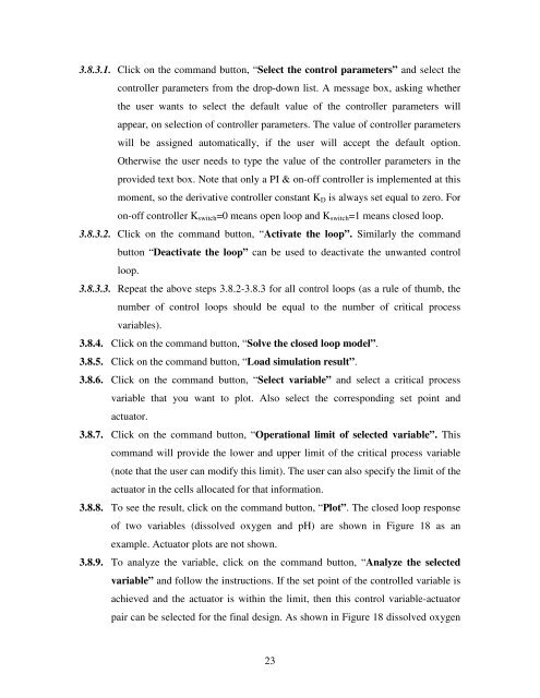
3.8.3.1. Click on the comm<strong>and</strong> button, “Select the control parameters” <strong>and</strong> select the<br />
controller parameters from the drop-down list. A message box, asking whether<br />
the user wants to select the default value <strong>of</strong> the controller parameters will<br />
appear, on selection <strong>of</strong> controller parameters. The value <strong>of</strong> controller parameters<br />
will be assigned automatically, if the user will accept the default option.<br />
Otherwise the user needs to type the value <strong>of</strong> the controller parameters in the<br />
provided text box. Note that only a PI & on-<strong>of</strong>f controller is implemented at this<br />
moment, so the derivative controller constant K D is always set equal to zero. For<br />
on-<strong>of</strong>f controller K switch =0 means open loop <strong>and</strong> K switch =1 means closed loop.<br />
3.8.3.2. Click on the comm<strong>and</strong> button, “Activate the loop”. Similarly the comm<strong>and</strong><br />
button “Deactivate the loop” can be used to deactivate the unwanted control<br />
loop.<br />
3.8.3.3. Repeat the above steps 3.8.2-3.8.3 <strong>for</strong> all control loops (as a rule <strong>of</strong> thumb, the<br />
number <strong>of</strong> control loops should be equal to the number <strong>of</strong> critical <strong>process</strong><br />
variables).<br />
3.8.4. Click on the comm<strong>and</strong> button, “Solve the closed loop model”.<br />
3.8.5. Click on the comm<strong>and</strong> button, “Load simulation result”.<br />
3.8.6. Click on the comm<strong>and</strong> button, “Select variable” <strong>and</strong> select a critical <strong>process</strong><br />
variable that you want to plot. Also select the corresponding set point <strong>and</strong><br />
actuator.<br />
3.8.7. Click on the comm<strong>and</strong> button, “Operational limit <strong>of</strong> selected variable”. This<br />
comm<strong>and</strong> will provide the lower <strong>and</strong> upper limit <strong>of</strong> the critical <strong>process</strong> variable<br />
(note that the user can modify this limit). The user can also specify the limit <strong>of</strong> the<br />
actuator in the cells allocated <strong>for</strong> that in<strong>for</strong>mation.<br />
3.8.8. To see the result, click on the comm<strong>and</strong> button, “Plot”. The closed loop response<br />
<strong>of</strong> two variables (dissolved oxygen <strong>and</strong> pH) are shown in Figure 18 as an<br />
example. Actuator plots are not shown.<br />
3.8.9. To analyze the variable, click on the comm<strong>and</strong> button, “Analyze the selected<br />
variable” <strong>and</strong> follow the instructions. If the set point <strong>of</strong> the controlled variable is<br />
achieved <strong>and</strong> the actuator is within the limit, then this control variable-actuator<br />
pair can be selected <strong>for</strong> the final design. As shown in Figure 18 dissolved oxygen<br />
23