Eclipse Combustion Engineering Guide - Burnerparts
Eclipse Combustion Engineering Guide - Burnerparts
Eclipse Combustion Engineering Guide - Burnerparts
You also want an ePaper? Increase the reach of your titles
YUMPU automatically turns print PDFs into web optimized ePapers that Google loves.
SIZING BRANCH PIPING BY THE EQUAL AREA METHOD<br />
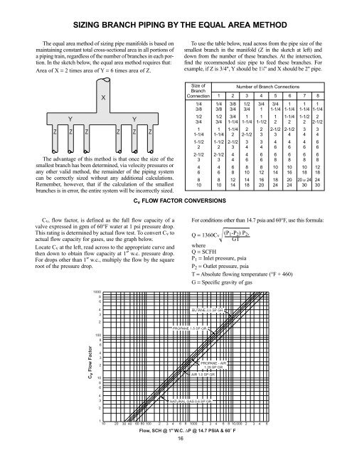
The equal area method of sizing pipe manifolds is based on<br />
maintaining constant total cross-sectional area in all portions of<br />
a piping train, regardless of the number of branches in each portion.<br />
In the sketch below, the equal area method requires that:<br />
Area of X = 2 times area of Y = 6 times area of Z.<br />
To use the table below, read across from the pipe size of the<br />
smallest branch in the manifold (Z in the sketch at left) and<br />
down from the number of these branches. At the intersection,<br />
find the recommended size pipe to feed these branches. For<br />
example, if Z is 3/4", Y should be 1 1 ⁄4" and X should be 2" pipe.<br />
Y<br />
X<br />
Z Z Z Z Z Z<br />
The advantage of this method is that once the size of the<br />
smallest branch has been determined, via velocity pressures or<br />
any other valid method, the remainder of the piping system<br />
can be correctly sized without any additional calculations.<br />
Remember, however, that if the calculation of the smallest<br />
branches is in error, the entire system will be incorrectly sized.<br />
Y<br />
Size of<br />
Branch<br />
Connection<br />
C v FLOW FACTOR CONVERSIONS<br />
Number of Branch Connections<br />
1 2 3 4 5 6 7 8<br />
1/4 1/4 3/8 1/2 3/4 3/4 1 1 1<br />
3/8 3/8 3/4 3/4 1 1-1/4 1-1/4 1-1/4 1-1/4<br />
1/2 1/2 3/4 1 1 1 1-1/4 1-1/2 2<br />
3/4 3/4 1-1/4 1-1/4 1-1/2 2 2 2 2-1/2<br />
1 1 1-1/4 2 2 2-1/2 2-1/2 3 3<br />
1-1/4 1-1/4 2 2-1/2 3 3 4 4 4<br />
1-1/2 1-1/2 2-1/2 3 3 4 4 4 6<br />
2 2 3 4 4 6 6 6 6<br />
2-1/2 2-1/2 4 4 6 6 6 6 6<br />
3 3 4 6 6 8 8 8 8<br />
4 4 6 8 8 10 10 10 12<br />
6 6 8 10 12 14 16 18 18<br />
8 8 12 14 16 18 20 20 or 24 24<br />
10 10 14 18 20 24 24 30 30<br />
Cv, flow factor, is defined as the full flow capacity of a<br />
valve expressed in gpm of 60°F water at 1 psi pressure drop.<br />
This rating is determined by actual flow test. To convert Cv to<br />
actual flow capacity for gases, use the graph below.<br />
Locate Cv at the left, read across to the appropriate curve and<br />
then down to obtain flow capacity at 1″ w.c. pressure drop.<br />
For drops other than 1″ w.c., multiply the flow by the square<br />
root of the pressure drop.<br />
For conditions other than 14.7 psia and 60°F, use this formula:<br />
Q = 1360Cv (P 1 -P 2 ) P 2 ,<br />
GT<br />
where<br />
Q = SCFH<br />
P 1 = Inlet pressure, psia<br />
P 2 = Outlet pressure, psia<br />
T = Absolute flowing temperature (°F + 460)<br />
G = Specific gravity of gas<br />
1000<br />
8<br />
6<br />
4<br />
3<br />
BUTANE 2.0 SP GR<br />
C v Flow Factor<br />
2<br />
100<br />
8<br />
6<br />
4<br />
3<br />
2<br />
10<br />
8<br />
6<br />
PROPANE 1.5 SP GR<br />
PROPANE - AIR<br />
1.29 SP GR<br />
AIR 1.0 SP GR<br />
4<br />
3<br />
2<br />
NATURAL GAS 0.6 SP GR<br />
1<br />
10 20 30 40 60 80 100 2 3 4 6 8 1000 2 3 4 6 8 10,000 2 3 4 6<br />
Flow, SCH @ 1" W.C. ∆P @ 14.7 PSIA & 60˚ F<br />
16


