Eclipse Combustion Engineering Guide - Burnerparts
Eclipse Combustion Engineering Guide - Burnerparts
Eclipse Combustion Engineering Guide - Burnerparts

You also want an ePaper? Increase the reach of your titles
YUMPU automatically turns print PDFs into web optimized ePapers that Google loves.
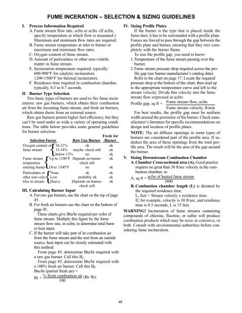
FUME INCERATION – SELECTION & SIZING GUIDELINES<br />
I. Process Information Required<br />
A. Fume stream flow rate, scfm or acfm. (If acfm,<br />
specify temperature at which flow is measured.)<br />
Maximum and minimum flow rates are required.<br />
B. Fume stream temperature at inlet to burner at<br />
maximum and minimum flow rates.<br />
C. Oxygen content of fume stream.<br />
D. Amount of particulates or other non-volatile<br />
matter in fume stream.<br />
E. Incineration temperature required, typically:<br />
600-900°F for catalytic incinerators<br />
1200-1500°F for thermal incinerators.<br />
F. Residence time required in combustion chamber,<br />
typically, 0.3 to 0.7 seconds.<br />
II. Burner Type Selection<br />
Two basic types of burners are used to fire fume incinerators:<br />
raw gas burners, which obtain their combustion<br />
air from the incoming fume stream, and fresh air burners,<br />
which obtain theirs from an external source.<br />
Raw gas burners permit higher fuel efficiency, but they<br />
can’t be used under as wide a variety of operating conditions.<br />
The table below provides some general guidelines<br />
for burner selection.<br />
Fresh Air<br />
Selection Factor Raw Gas Burner Burner<br />
Oxygen content of 18-21% ok ok<br />
fume stream 13-18% maybe–check mfr. ok<br />
below 13% no ok<br />
Fume stream Up to 1100°F Depends on burner– ok<br />
{<br />
{<br />
{<br />
temperature<br />
check mfr.<br />
entering burner Over 1100°F no ok<br />
Particulates or None ok ok<br />
other non-vola- Low probably ok ok<br />
tiles in stream Heavy Depends on burner– ok<br />
check mfr.<br />
III. Calculating Burner Input<br />
A. For raw gas burners, use the chart on the top of page<br />
45.<br />
B. For fresh air burners use the chart on the bottom of<br />
page 45.<br />
These charts give Btu/hr required per scfm of<br />
fume stream. Multiply this figure by the fume<br />
stream flow rate, in scfm, to determine total burner<br />
heat input.<br />
C. If the burner will take part of its combustion air<br />
from the fume stream and the rest from an outside<br />
source, heat input can be closely estimated with<br />
this method:<br />
From page 45, deteremine Btu/hr required with<br />
a raw gas burner. Call this B r .<br />
From page 45, deteremine Btu/hr required with<br />
a 100% fresh air burner. Call this B f .<br />
Btu/hr (partial fresh air) =<br />
Br + % fresh combustion air (Bf–Br)<br />
100<br />
IV. Sizing Profile Plates<br />
If the burner is the type that is placed inside the<br />
fume duct, it has to be surrounded with a profile plate.<br />
Fumes are forced to pass through the gap between the<br />
profile plate and burner, ensuring that they mix completely<br />
with the burner flame.<br />
To size the profile gap, you need to know:<br />
1.Temperature of the fume stream passing over the<br />
burner,<br />
2.Fume stream pressure drop required across the profile<br />
gap (see burner manufacturer’s catalog data).<br />
Refer to the chart on page 17. Locate the required<br />
pressure drop at the bottom of the chart, then read up<br />
to the appropriate temperature curve and left to the<br />
stream velocity. Divide this velocity into the fume<br />
stream flow expressed in acfm:<br />
Profile gap, sq ft = Fume stream flow, acfm<br />
Fume stream velocity, ft/min<br />
For best results, the profile gap must be uniform<br />
width around the perimeter of the burner. Check manufacturer’s<br />
literature for specific recommendations on<br />
design and location of profile plates.<br />
NOTE: The air diffuser openings in some types of<br />
burners are considered part of the profile area. If so,<br />
deduct the area of these openings from the total profile<br />
area. The result will be the area of the gap around<br />
the burner.<br />
V. Sizing Downstream <strong>Combustion</strong> Chamber<br />
A. Chamber Cross-sectional area (A), Good practice<br />
requires no great than 30 ft/sec velocity in the combustion<br />
chamber, so<br />
A, sq ft =<br />
acfm of heated fume stream<br />
1800<br />
B. <strong>Combustion</strong> chamber length (L) is dictated by<br />
the required residence time.<br />
L, feet = Stream velocity x residence time.<br />
If, for example, velocity is 30 ft/sec, and residence<br />
time is 0.5 seconds, L is 15 feet.<br />
WARNING! Incineration of fume streams containing<br />
compounds of chlorine, fluorine, or sulfur will produce<br />
combustion products which may be toxic or corrosive, or<br />
both. Consult with environmental authorities before considering<br />
fume incineration.<br />
46