Eclipse Combustion Engineering Guide - Burnerparts
Eclipse Combustion Engineering Guide - Burnerparts
Eclipse Combustion Engineering Guide - Burnerparts

You also want an ePaper? Increase the reach of your titles
YUMPU automatically turns print PDFs into web optimized ePapers that Google loves.
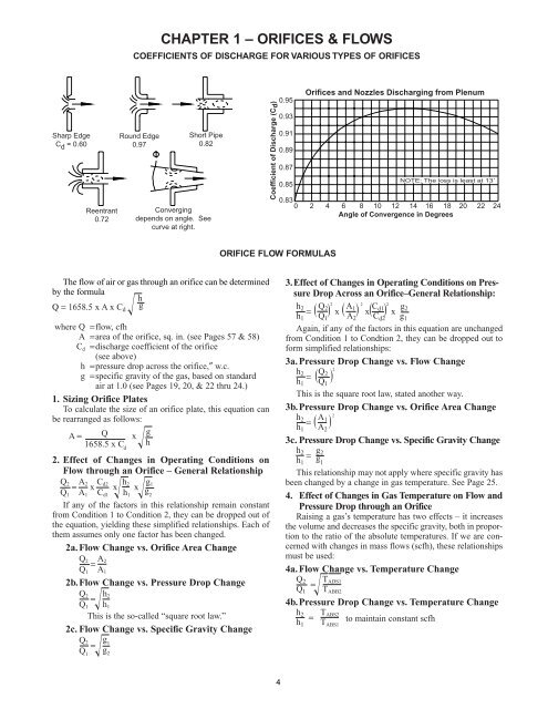
CHAPTER 1 – ORIFICES & FLOWS<br />
COEFFICIENTS OF DISCHARGE FOR VARIOUS TYPES OF ORIFICES<br />
Sharp Edge<br />
C d = 0.60<br />
Reentrant<br />
0.72<br />
Round Edge<br />
0.97<br />
Short Pipe<br />
0.82<br />
Converging<br />
depends on angle. See<br />
curve at right.<br />
Coefficient of Discharge (C d )<br />
0.95<br />
Orifices and Nozzles Discharging from Plenum<br />
0.93<br />
0.91<br />
0.89<br />
0.87<br />
NOTE: The loss is least at 13˚<br />
0.85<br />
0.83<br />
0 2 4 6 8 10 12 14 16 18 20 22 24<br />
Angle of Convergence in Degrees<br />
ORIFICE FLOW FORMULAS<br />
The flow of air or gas through an orifice can be determined 3.Effect of Changes in Operating Conditions on Pressure<br />
Drop Across an Orifice–General Relationship:<br />
by the formula<br />
h<br />
Q = 1658.5 x Ax C d g<br />
h 2<br />
= Q 2 2 x A 1 2 x C d1 2 x g 2<br />
h 1<br />
(<br />
Q 1<br />
) (<br />
A 2<br />
) (<br />
C d2<br />
)<br />
g 1<br />
where Q =flow, cfh<br />
Again, if any of the factors in this equation are unchanged<br />
A =area of the orifice, sq. in. (see Pages 57 & 58) from Condition 1 to Condtion 2, they can be dropped out to<br />
C d =discharge coefficient of the orifice<br />
form simplified relationships:<br />
(see above)<br />
3a.Pressure Drop Change vs. Flow Change<br />
h =pressure drop across the orifice,″ w.c.<br />
h<br />
g =specific gravity of the gas, based on standard<br />
2<br />
= Q 2 2<br />
h<br />
air at 1.0 (see Pages 19, 20, & 22 thru 24.)<br />
1<br />
(<br />
Q 1<br />
)<br />
This is the square root law, stated another way.<br />
1. Sizing Orifice Plates<br />
To calculate the size of an orifice plate, this equation can 3b.Pressure Drop Change vs. Orifice Area Change<br />
be rearranged as follows:<br />
h 2<br />
= A 1 2<br />
h<br />
A= Q x<br />
g<br />
1<br />
(<br />
A 2<br />
)<br />
1658.5 x C d<br />
h<br />
3c.Pressure Drop Change vs. Specific Gravity Change<br />
h 2<br />
= g 2<br />
2. Effect of Changes in Operating Conditions on h 1<br />
g 1<br />
Flow through an Orifice – General Relationship This relationship may not apply where specific gravity has<br />
Q 2<br />
= A2 x Cd2 x h2 x g 1<br />
been changed by a change in gas temperature. See Page 25.<br />
Q 1 A 1 C d1 h 1<br />
g 2<br />
4. Effect of Changes in Gas Temperature on Flow and<br />
If any of the factors in this relationship remain constant Pressure Drop through an Orifice<br />
from Condition 1 to Condition 2, they can be dropped out of Raising a gas’s temperature has two effects – it increases<br />
the equation, yielding these simplified relationships. Each of the volume and decreases the specific gravity, both in proportion<br />
to the ratio of the absolute temperatures. If we are con-<br />
them assumes only one factor has been changed.<br />
2a.Flow Change vs. Orifice Area Change<br />
cerned with changes in mass flows (scfh), these relationships<br />
Q 2<br />
= A must be used:<br />
2<br />
Q 1 A 1<br />
4a.Flow Change vs. Temperature Change<br />
2b.Flow Change vs. Pressure Drop Change<br />
Q 2<br />
= T ADS1<br />
Q 2<br />
= h Q 1 T ABB2<br />
2<br />
Q 1 h 1<br />
4b.Pressure Drop Change vs. Temperature Change<br />
This is the so-called “square root law.”<br />
h 2<br />
= T ABS2<br />
h 1 T to maintain constant scfh<br />
ABS1<br />
2c.Flow Change vs. Specific Gravity Change<br />
Q 2<br />
= g 1<br />
Q 1<br />
g 2<br />
4