Eclipse Combustion Engineering Guide - Burnerparts
Eclipse Combustion Engineering Guide - Burnerparts
Eclipse Combustion Engineering Guide - Burnerparts

You also want an ePaper? Increase the reach of your titles
YUMPU automatically turns print PDFs into web optimized ePapers that Google loves.
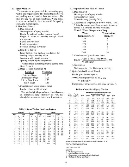
II. Spray Washers<br />
Three methods are presented for calculating spray<br />
washer heat requirements. The first is the most accurate,<br />
making use of detailed heat loss factors. The<br />
other two are rule-of-thumb methods. While not as<br />
accurate as method A, they are useful for quickly<br />
estimating burner inputs.<br />
A. Heat Loss Method<br />
1.Data required:<br />
Gpm capacity of spray nozzles<br />
Height & width of washer housing (hood)<br />
Height & width of opening through which<br />
work passes<br />
Liquid pressure head<br />
Liquid temperature<br />
Location of stage in washer<br />
2.Heat Loss factors<br />
From Table 2, find the heat loss factors for<br />
housing height opening width<br />
housing width liquid pressure<br />
opening height liquid temperature<br />
Add all these factors together to get the combined<br />
factor, f.<br />
3.Stage location multiplier, M<br />
Location Multiplier<br />
Entrance Stage 1.75<br />
Intermediate Stage 1.00<br />
After a Cold Rinse 1.25<br />
Exist Stage 1.50<br />
4.Calculation of Gross Burner Input<br />
Btu/hr = Gpm x 500 x f x M<br />
This method yields gross burner input because<br />
an immersion tube efficiency of 70% has<br />
already been assumed in the heat loss factors.<br />
Table 2. Spray Washer Heat Loss Factors<br />
Housing Opening Liquid<br />
Wide High Wide High Press. Temp.<br />
Ft. f Ft. f Ft. f Ft. f PSIG f °F f<br />
2 .7 1 .8 140 .4<br />
3 .8 1 .3 2 .9 1 .5 5 .4 145 .5<br />
4 .9 2 .4 3 1.0 2 .6 7.5 .5 150 .6<br />
5 1.0 3 .5 4 1.1 3 .7 10 .6 155 .7<br />
6 1.1 4 .6 5 1.2 4 .8 12.5 .7 160 .8<br />
7 1.2 5 .7 6 1.3 5 .9 15 .8 165 .9<br />
8 1.3 6 .8 7 1.4 6 1.0 17.5 .9 170 1.0<br />
9 1.4 7 .9 8 1.5 7 1.1 20 1.0 175 1.3<br />
10 1.5 8 1.0 9 1.6 8 1.3 22.5 1.2 180 1.6<br />
11 1.6 9 1.1 10 1.7 9 1.5 30 1.4 185 1.9<br />
12 1.7 10 1.2 11 1.8 10 1.7 32.5 1.6 190 2.2<br />
13 1.8 11 1.3 12 1.9 11 1.9 35 1.8<br />
14 1.9 12 1.4 13 2.0 12 2.1 37.5 2.0<br />
15 2.0 13 1.5 14 2.1 13 2.3 40 2.2<br />
16 2.1 14 1.6 15 2.2 14 2.5 50 2.6<br />
17 2.2 100 3.5<br />
B. Temperature Drop Rule of Thumb<br />
1.Data required:<br />
Gpm capacity of spray nozzles<br />
Temperature of liquid<br />
Tube efficiency (usually 70%)<br />
2.Approximate temperature drop of water. Table<br />
3 lists the approximate loss in water temperature<br />
as it is sprayed onto the workload.<br />
Table 3. Water Temperature Drop<br />
Water<br />
Temperature<br />
Temperature, °F Drop, °F<br />
150 5<br />
160 6<br />
170 7<br />
180 8<br />
190 9<br />
200 10<br />
3.Calculation of gross burner input.<br />
Btu/hr = Gpm x 500 x Temp Drop x 100<br />
% Efficiency<br />
4.Tank sizing<br />
Tank capacity = 3 x Gpm spray capacity<br />
C. Quick Method Rule of Thumb<br />
Btu/hr gross burner input =<br />
4000 x Gpm sprayed @ 30 psi x 100<br />
% Efficiency<br />
Capacities of spray nozzles are listed in Table 4.<br />
Table 4. Capacities of Spray Nozzles<br />
Gallons per minute of water through<br />
PSI Ft. Hd. a nozzle diameter of:<br />
Press (Approx.) 1/4" 5/16" 3/8" 7/16" 1/2" 5/8" 3/4"<br />
5 11.5 3.3 5.2 7.4 10.2 13.3 20.8 30.0<br />
10 23.0 4.7 7.3 10.4 14.3 18.7 29.3 42.3<br />
15 35.0 5.8 9.1 12.9 17.7 23.2 36.2 52.3<br />
20 46.5 6.7 10.5 14.8 20.7 26.7 41.8 60.5<br />
25 57.5 7.4 11.7 16.6 22.7 29.7 46.8 67.0<br />
30 68.5 8.1 12.9 18.2 24.8 32.4 50.7 73.0<br />
35 81.0 8.8 13.8 19.7 27.0 35.2 55.1 79.5<br />
40 92.5 9.4 14.8 21.3 28.8 37.7 58.9 85.0<br />
45 104.0 10.0 15.7 22.4 30.6 39.9 65.1 90.0<br />
50 115.0 10.5 16.5 23.5 32.1 42.0 65.7 94.6<br />
55 126.5 11.0 17.3 24.7 33.7 44.1 68.9 99.5<br />
60 138.0 11.0 18.1 25.8 35.2 46.1 72.1 104.0<br />
65 150.0 12.0 18.8 26.9 36.7 48.0 75.0 108.2<br />
70 162.0 12.4 19.6 27.9 38.1 49.7 77.9 112.0<br />
75 172.0 12.9 20.2 28.9 39.4 51.5 80.6 116.0<br />
80 184.5 13.3 20.9 29.9 40.7 53.3 83.1 119.9<br />
85 195.0 13.7 21.5 30.7 41.8 54.7 85.5 123.5<br />
90 205.0 14.0 22.0 31.4 42.9 56.2 87.7 126.7<br />
95 214.5 14.4 22.6 32.1 43.9 57.5 89.8 129.5<br />
100 224.0 14.6 23.1 32.8 44.8 58.7 91.7 132.0<br />
Above values are based on an orifice discharge coefficient of .80<br />
ORIFICE FLOW EQUATION:<br />
Q = 19.65 C D 2 H<br />
WHERE:<br />
Q = Gallons per minute<br />
D = Diameter of orifice in inches<br />
H = Pressure drop across orifice in feet head<br />
C = Orifice discharge coefficient<br />
48