
Create successful ePaper yourself
Turn your PDF publications into a flip-book with our unique Google optimized e-Paper software.
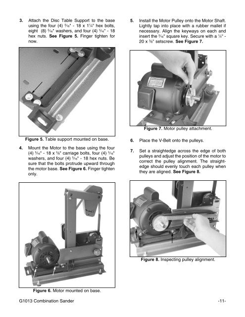
3. Attach the Disc Table Support to the base<br />
using the four (4) 5 ⁄16" - 18 x 1 1 ⁄4" hex bolts,<br />
eight (8) 5 ⁄16" washers, and four (4) 5 ⁄16" - 18<br />
hex nuts. See Figure 5. Finger tighten for<br />
now.<br />
5. Install the Motor Pulley onto the Motor Shaft.<br />
Lightly tap into place with a rubber mallet if<br />
necessary. Align the keyways on each and<br />
insert the 3 ⁄16'' square key. Secure with a 1 ⁄4" -<br />
20 x 3 ⁄8'' setscrew. See Figure 7.<br />
Figure 7. Motor pulley attachment.<br />
Figure 5. Table support mounted on base.<br />
4. Mount the Motor to the base using the four<br />
(4) 5 ⁄16" - 18 x 5 ⁄8" carriage bolts, four (4) 5 ⁄16"<br />
washers, and four (4) 5 ⁄16" - 18 hex nuts. Be<br />
sure that the bolts protrude upward through<br />
the motor base. See Figure 6. Finger tighten<br />
only.<br />
6. Place the V-Belt onto the pulleys.<br />
7. Set a straightedge across the edge of both<br />
pulleys and adjust the position of the motor to<br />
correct the pulley alignment. The straightedge<br />
should evenly touch each pulley when<br />
they are aligned. See Figure 8.<br />
Figure 8. Inspecting pulley alignment.<br />
Figure 6. Motor mounted on base.<br />
<strong>G1013</strong> Combination Sander -11-