
Create successful ePaper yourself
Turn your PDF publications into a flip-book with our unique Google optimized e-Paper software.
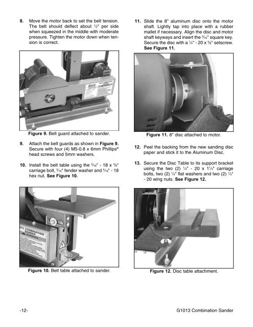
8. Move the motor back to set the belt tension.<br />
The belt should deflect about 1 ⁄2" per side<br />
when squeezed in the middle with moderate<br />
pressure. Tighten the motor down when tension<br />
is correct.<br />
11. Slide the 8'' aluminum disc onto the motor<br />
shaft. Lightly tap into place with a rubber<br />
mallet if necessary. Align the disc and motor<br />
shaft keyways and insert the 3 ⁄16'' square key.<br />
Secure the disc with a 1 ⁄4" - 20 x 3 ⁄8'' setscrew.<br />
See Figure 11.<br />
Figure 9. Belt guard attached to sander.<br />
9. Attach the belt guards as shown in Figure 9.<br />
Secure with four (4) M5-0.8 x 6mm Phillips ®<br />
head screws and 5mm washers.<br />
10. Install the belt table using the 5 ⁄16" - 18 x 5 ⁄8"<br />
carriage bolt, 5 ⁄16" fender washer and 5 ⁄16" - 18<br />
hex nut. See Figure 10.<br />
Figure 11. 8" disc attached to motor.<br />
12. Peel the backing from the new sanding disc<br />
paper and stick it to the Aluminum Disc.<br />
13. Secure the Disc Table to its support bracket<br />
using the two (2) 1 ⁄4" - 20 x 1 1 ⁄4" carriage<br />
bolts, two (2) 1 ⁄4" flat washers and two (2) 1 ⁄4"<br />
- 20 wing nuts. See Figure 12.<br />
Figure 10. Belt table attached to sander.<br />
Figure 12. Disc table attachment.<br />
-12- <strong>G1013</strong> Combination Sander