Spesification - Sør-Norge Aluminium AS
Spesification - Sør-Norge Aluminium AS
Spesification - Sør-Norge Aluminium AS

You also want an ePaper? Increase the reach of your titles
YUMPU automatically turns print PDFs into web optimized ePapers that Google loves.
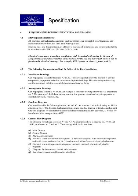
<strong>Spesification</strong><br />
4. REQUIREMENTS FOR DOCUMENTATION AND TRAINING<br />
4.1 Drawings and Descriptions<br />
All drawings and technical descriptions shall have Norwegian or English text. Operations and<br />
maintenance instructions, etc. shall have Norwegian text.<br />
Drawing basis and documentation, in addition to marking of installations and components shall be<br />
in accordance with NEK 144. (EN 60617 / EN 61346)<br />
Electrical components in machine installations shall be marked with a letter for the type of<br />
component used and also be marked with a number for the side and power path where it can be<br />
found on the electrical drawings. For example, M12.2 (motor on sheet 12, power path 2).<br />
4.2 The Following Documentation Shall Be Delivered for Each Installation:<br />
4.2.1 Installation Drawings<br />
Can be prepared in standard formats A3 to A0. The drawings shall show the position of electric<br />
components, equipment and cable connections in plants/buildings. The numbering and marking<br />
must be consistent with the associated diagrams and drawing basis.<br />
4.2.2 Arrangement Drawings<br />
Can be prepared in format A4 to A1. An example is shown in drawing number 19182, attachment<br />
no. 3. The drawing(s) shall show internal construction, placement and marking of equipment in<br />
distribution boards, consoles, etc.<br />
4.2.3 One-Line Diagram<br />
Can be delivered in the following formats; A4 and A3. An example is show in drawing no. 19183,<br />
attachment no. 4. The drawing shall represent one single one-line diagram without control current.<br />
One-line diagrams for transformer stations (distribution stations) shall be delivered, as well as for<br />
installations with voltages above 400V.<br />
4.2.4 Current Flow Diagram<br />
The following formats are accepted: A4 and A3. An example is show in drawing no. 19185 and<br />
19186, attachment no. 5 and no. 6. The drawings shall be divided into:<br />
a) Main Current<br />
b) Control Current<br />
c) Alarm, error messages<br />
d) Electrical schematics/hydraulic diagrams, i.e. hydraulic diagrams with electrical components<br />
(solenoid valves, end switches, etc.) clearly marked with reference to electrical schematics.<br />
e) Electrical schematics/pneumatic diagrams, similar to electrical schematics/hydraulic<br />
diagrams.<br />
f) Diagrams for instruments, control and electronics.<br />
g) Associated connection tables and terminal lists.<br />
2.3 Electro technical specification rev 8.1 Side 13 av 35