Motorvision Drawout (MVD) Technical Manual - PBSI Group Ltd
Motorvision Drawout (MVD) Technical Manual - PBSI Group Ltd
Motorvision Drawout (MVD) Technical Manual - PBSI Group Ltd

Create successful ePaper yourself
Turn your PDF publications into a flip-book with our unique Google optimized e-Paper software.
<strong>MVD</strong> TECHNICAL MANUAL<br />
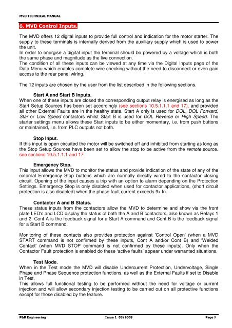
6. <strong>MVD</strong> Control Inputs.<br />
The <strong>MVD</strong> offers 12 digital inputs to provide full control and indication for the motor starter. The<br />
supply to these terminals is internally derived from the auxiliary supply which is used to power<br />
the unit.<br />
In order to energise a digital input the terminal should be powered by a voltage which is both<br />
the same phase and magnitude as the live connection.<br />
The condition of all these inputs can be viewed at any time via the Digital Inputs page of the<br />
Data Menu which enables complete wire checking without the need to disconnect or even gain<br />
access to the rear panel wiring.<br />
The 12 inputs are chosen by the user from the list described in the following sections.<br />
Start A and Start B Inputs.<br />
When one of these inputs are closed the corresponding output relay is energised as long as the<br />
Start Setup Sources has been set accordingly (see sections 10.5.1.1.1 and 17), and provided<br />
all other External Faults are in the healthy state. Start A only is used for DOL, DOL Forward,<br />
Star or Low Speed contactors whilst Start B is used for DOL Reverse or High Speed. The<br />
starter settings menu allows these Start inputs to be either momentary, i.e. from push buttons<br />
or maintained, i.e. from PLC outputs not both.<br />
Stop Input.<br />
If this input is open circuited the motor will be switched off and inhibited from starting as long as<br />
the Stop Setup Sources have been set to allow the stop to be active from the remote source.<br />
see sections 10.5.1.1.1 and 17.<br />
Emergency Stop.<br />
This input allows the <strong>MVD</strong> to monitor the status and provide indication of the state of any of the<br />
external Emergency Stop buttons which are normally directly wired to the contactor closing<br />
circuit. Opening of the input causes a trip with an option to alarm depending on the Protection<br />
Settings. Emergency Stop is only disabled when used for contactor applications, (short circuit<br />
protection is also disabled) when the phase fault current exceeds 9x In.<br />
Contactor A and B Status.<br />
These status inputs from the contactors allow the <strong>MVD</strong> to determine and show via the front<br />
plate LED's and LCD display the status of both the A and B contactors, also known as Relays 1<br />
and 2. Cont A is the feedback signal for a Start A command and Cont B is the feedback signal<br />
for a Start B command.<br />
Monitoring of these contacts also provides protection against 'Control Open' (when a <strong>MVD</strong><br />
START command is not confirmed by these inputs, Cont A and/or Cont B) and 'Welded<br />
Contact' (when <strong>MVD</strong> STOP command is not confirmed by these inputs). Only when the<br />
Contactor Fault protection is enabled do these ‘active faults’ appear under warranted situations.<br />
Test Mode.<br />
When in the Test mode the <strong>MVD</strong> will disable Undercurrent Protection, Undervoltage, Single<br />
Phase and Phase Sequence protection functions, as well as the External Faults if set to Disable<br />
in Test.<br />
This allows full functional testing to be performed without the need for voltage or current<br />
injection and will allow secondary injection testing to be carried out on all protective functions<br />
except for those disabled by the feature.<br />
P&B Engineering Issue 1 03/2008 Page 9