Motorvision Drawout (MVD) Technical Manual - PBSI Group Ltd
Motorvision Drawout (MVD) Technical Manual - PBSI Group Ltd
Motorvision Drawout (MVD) Technical Manual - PBSI Group Ltd

Create successful ePaper yourself
Turn your PDF publications into a flip-book with our unique Google optimized e-Paper software.
<strong>MVD</strong> TECHNICAL MANUAL<br />
Undervoltage Restart Time.<br />
This setting determines the allowable off time (the time a relay can be powered off or<br />
without nominal voltage) such that if the power is restored or the voltage returns to<br />
normal within this time a restart can occur.<br />
Voltage loss could be result of upstream supplies changing over, an HV motor starting or<br />
some other condition which causes downstream connected drives to either trip on<br />
undervoltage protection or cause contactors to drop out.<br />
Undervoltage Restart Delay.<br />
Once power has returned the restart delay can be used to help control the sequence of<br />
a process restart after an outage. This is a settable time to hold off automated start<br />
control after voltage restoration.<br />
This can be used to prevent an entire bus system of motor starters from trying to<br />
reaccelerate at the same time.<br />
Restart Sense.<br />
This setting, which can be set to ‘Supply’ or ‘Supply or Reference’, determines the signal<br />
that is examined after a power loss to determine whether an Undervoltage Restart will<br />
occur.<br />
If it is set to ‘Supply’ then after a power loss and when the supply to the relay is active<br />
again a restart will occur.<br />
If it is set to ‘Supply or Reference’ the relay will examine if there is voltage on the Busbars<br />
that supply the motor. Specifically, if the voltage dips below 65% of the line voltage<br />
then a Stop is called, if the voltage is restored to above 65% of the line voltage (within<br />
the set Restart Time) then the <strong>MVD</strong> will orchestrate the restart. This setting is for the<br />
case where the relay is powered off an Auxiliary supply and not from the supplying Busbars.<br />
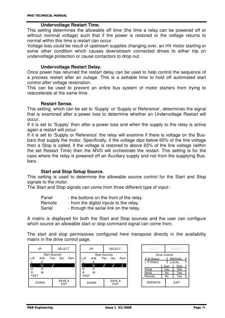
Start and Stop Setup Source.<br />
This setting is used to determine the allowable source control for the Start and Stop<br />
signals to the motor.<br />
The Start and Stop signals can come from three different type of input:-<br />
Panel<br />
Remote<br />
Serial<br />
- the buttons on the front of the relay.<br />
- from the digital inputs to the relay.<br />
- through the serial link on the relay.<br />
A matrix is displayed for both the Start and Stop sources and the user can configure<br />
which source an allowable start or stop command signal can come from.<br />
The start and stop permissives configured here transpose directly in the availability<br />
matrix in the drive control page.<br />
UP SELECT<br />
Start Sources<br />
L/R A/M Pan Ser Rem<br />
L A<br />
L M<br />
R A<br />
R M<br />
TEST<br />
DOWN<br />
SAVE &<br />
EXIT<br />
UP SELECT<br />
Stop Sources<br />
L/R A/M Pan Ser Rem<br />
L A<br />
L M<br />
R A<br />
R M<br />
TEST<br />
DOWN<br />
SAVE &<br />
EXIT<br />
AUTO<br />
REMOTE<br />
Drive Control<br />
A M Status MANUAL<br />
L R Status LOCAL<br />
Start Stop<br />
Panel Yes Yes<br />
Serial No Yes<br />
Remote No Yes<br />
OPERATE<br />
EXIT<br />
P&B Engineering Issue 1 03/2008 Page 39