Motorvision Drawout (MVD) Technical Manual - PBSI Group Ltd
Motorvision Drawout (MVD) Technical Manual - PBSI Group Ltd
Motorvision Drawout (MVD) Technical Manual - PBSI Group Ltd

Create successful ePaper yourself
Turn your PDF publications into a flip-book with our unique Google optimized e-Paper software.
<strong>MVD</strong> TECHNICAL MANUAL<br />
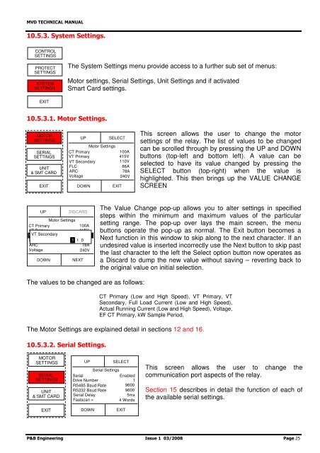
10.5.3. System Settings.<br />
CONTROL<br />
SETTINGS<br />
PROTECT<br />
SETTINGS<br />
SYSTEM<br />
SETTINGS<br />
The System Settings menu provide access to a further sub set of menus:<br />
Motor settings, Serial Settings, Unit Settings and if activated<br />
Smart Card settings.<br />
EXIT<br />
10.5.3.1. Motor Settings.<br />
MOTOR<br />
SETTINGS<br />
SERIAL<br />
SETTINGS<br />
UNIT<br />
& SMT CARD<br />
EXIT<br />
UP<br />
Motor Settings<br />
CT Primary<br />
VT Primary<br />
VT Secondary<br />
FLC<br />
ARC<br />
Voltage<br />
DOWN<br />
SELECT<br />
EXIT<br />
100A<br />
415V<br />
110V<br />
86A<br />
78A<br />
240V<br />
This screen allows the user to change the motor<br />
settings of the relay. The list of values to be changed<br />
can be scrolled through by pressing the UP and DOWN<br />
buttons (top-left and bottom left). A value can be<br />
selected to have its value changed by pressing the<br />
SELECT button (top-right) when the value is<br />
highlighted. This then brings up the VALUE CHANGE<br />
SCREEN<br />
UP<br />
Motor Settings<br />
CT Primary<br />
100A<br />
VT Primary<br />
415V<br />
VT VT Secondary Secondary 110V<br />
FLC<br />
1 1 086A<br />
ARC<br />
78A<br />
Voltage<br />
240V<br />
DOWN<br />
DISCARD<br />
NEXT<br />
The Value Change pop-up allows you to alter settings in specified<br />
steps within the minimum and maximum values of the particular<br />
setting range. The pop-up over lays the main screen, the menu<br />
buttons operate the pop-up as normal. The Exit button becomes a<br />
Next function in this window to skip along to the next character. If an<br />
undesired value is inserted incorrectly use the Next button to skip past<br />
the last character to the left the Select option button now operates as<br />
a Discard to dump the new value without saving – reverting back to<br />
the original value on initial selection.<br />
The values to be changed are as follows:<br />
CT Primary (Low and High Speed), VT Primary, VT<br />
Secondary, Full Load Current (Low and High Speed),<br />
Actual Running Current (Low and High Speed), Voltage,<br />
EF CT Primary, kW Sample Period,<br />
The Motor Settings are explained detail in sections 12 and 16.<br />
10.5.3.2. Serial Settings.<br />
MOTOR<br />
SETTINGS<br />
SERIAL<br />
SETTINGS<br />
UNIT<br />
& SMT CARD<br />
UP<br />
SELECT<br />
Serial Settings<br />
Serial<br />
Enabled<br />
Drive Number<br />
1<br />
RS485 Baud Rate 9600<br />
RS232 Baud Rate 9600<br />
Serial Delay<br />
5ms<br />
Fastscan =<br />
4 Words<br />
This screen allows the user to change the<br />
communication port aspects of the relay.<br />
Section 15 describes in detail the function of each of<br />
the available serial settings.<br />
EXIT<br />
DOWN<br />
EXIT<br />
P&B Engineering Issue 1 03/2008 Page 25