C 3201 - Dimotec
C 3201 - Dimotec
C 3201 - Dimotec

Create successful ePaper yourself
Turn your PDF publications into a flip-book with our unique Google optimized e-Paper software.
Technical specification<br />
Submersible pump C <strong>3201</strong>, 50 Hz
C <strong>3201</strong><br />
SUBCAB ® 4G25 mm 2<br />
4G25+2x1,5 mm 2<br />
4G35 mm 2<br />
4G35+2x1,5 mm 2<br />
Y/D start<br />
SUBCAB ® 2x4G10+2x1,5 mm 2<br />
7G6+2x1,5 mm 2<br />
Monitoring equipment<br />
Thermal contacts opening temperature 125 °C<br />
Material<br />
Impeller<br />
Cast iron<br />
Pump housing<br />
Cast iron<br />
Stator housing<br />
Cast iron<br />
Shaft<br />
Carbon steel<br />
O-rings<br />
Nitrile rubber<br />
Mechanical face seals<br />
Alternative Inner seal Outer seal<br />
1 Corrosion resistant Corrosion resistant<br />
C <strong>3201</strong><br />
cemented carbide/ cemented carbide/<br />
Corrosion resistant<br />
cemented carbide<br />
Corrosion resistant<br />
cemented carbide<br />
Product<br />
Surface Treatment<br />
All cast parts are primed with a water-borne primer. The finishing coat<br />
Submersible pump for pumping clean water, surface water and waste<br />
is a high-solid two pack paint.<br />
water containing solids or long-fibred material.<br />
Denomination<br />
Product code <strong>3201</strong>.180<br />
Weight<br />
See dimensional drawing.<br />
Process data<br />
Installation P, S, T, Z<br />
Impeller characteristics LT, MT, HT, SH<br />
Option<br />
<strong>3201</strong>.091 Ex. proof design<br />
<strong>3201</strong>.280 Stainless steel design<br />
Liquid temperature max +40 °C<br />
<strong>3201</strong>.980 Industrial design<br />
Depth of immersion<br />
max 20 m<br />
<strong>3201</strong>.290 Stainless steel/Ex proof design<br />
The pH of the pumped liquid pH 5,5-14<br />
Warm liquid version on request<br />
Liquid density max. 1100 kg/m 3 Leakage sensor in stator housing<br />
FLS<br />
Impeller throughlet<br />
See Motor rating table<br />
Leakage sensor in oil housing<br />
CLS<br />
Motor data<br />
Frequency<br />
50 Hz<br />
Surface treatment<br />
Epoxy treatment<br />
Other cables<br />
Zinc anodes<br />
Insulation class H (+180 °C)<br />
Accessories<br />
Voltage variation<br />
- continuously running max ± 5%<br />
Discharge connections, adapters, hose connections and other<br />
mechanical accessories.<br />
- intermittent running max ± 10%<br />
Electrical accessories such as pump controller, control panels, starters,<br />
Voltage imbalance between phases max 2%<br />
monitoring relays, cables.<br />
No. of starts/hour max 30<br />
See separate booklet or www.flygt.com, for further information.<br />
Cable<br />
Direct-on-line start<br />
SUBCAB ® 4G10+2x1,5 mm 2<br />
3
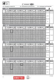
C <strong>3201</strong><br />
LT-Motor rating and performance<br />
curve<br />
P<br />
2<br />
[kW]<br />
Curve/Impeller No<br />
Rated power, kW<br />
Rated current, A<br />
Starting current, A<br />
Power factor cos ϕ<br />
Impeller thoughlet, mm<br />
Ex proof version available<br />
Installation<br />
P S T Z<br />
400 V, 50 Hz, 3 ~, 970 r/min<br />
624 22,0 45 300 0,82 102 • • • • •<br />
625 22,0 45 300 0,82 102 • • • • •<br />
626 22,0 45 300 0,82 102 • • • • •<br />
627 22,0 45 300 0,82 102 • • • • •<br />
628 22,0 45 300 0,82 102 • • • • •<br />
629 22,0 45 300 0,82 102 • • • • •<br />
25<br />
20<br />
15<br />
10<br />
12<br />
10<br />
8<br />
6<br />
H [m]<br />
624<br />
625<br />
626<br />
627<br />
628<br />
629<br />
LT<br />
Y/D starting current is approximately 1/3 of D starting current.<br />
4<br />
2<br />
624<br />
626<br />
627 625<br />
629 628<br />
0<br />
0 50 100 150 200 250 300 350 400<br />
Q [l/s]<br />
MT-Motor rating and performance<br />
curve<br />
P<br />
2<br />
[kW]<br />
Curve/Impeller No<br />
Rated power, kW<br />
Rated current, A<br />
Starting current, A<br />
Power factor cos ϕ<br />
Impeller thoughlet, mm<br />
Ex proof version available<br />
Installation<br />
P S T Z<br />
400 V, 50 Hz, 3 ~, 970 r/min<br />
630 22,0 45 300 0,82 84 • • • • •<br />
632 22,0 45 300 0,82 84 • • • • •<br />
634 22,0 45 300 0,82 84 • • • • •<br />
635 22,0 45 300 0,82 84 • • • • •<br />
636 22,0 45 300 0,82 84 • • • • •<br />
637 22,0 45 300 0,82 84 • • • • •<br />
638 22,0 45 300 0,82 84 • • • • •<br />
Y/D starting current is approximately 1/3 of D starting current.<br />
20<br />
15<br />
10<br />
24<br />
20<br />
16<br />
12<br />
8<br />
4<br />
H [m]<br />
630<br />
635<br />
632<br />
634 636<br />
637<br />
638<br />
MT<br />
635<br />
630<br />
632<br />
634<br />
638 637<br />
636<br />
0<br />
0 40 80 120 160 200<br />
Q [l/s]<br />
4
C <strong>3201</strong><br />
HT-Motor rating and performance<br />
curve<br />
P<br />
2<br />
[kW]<br />
Curve/Impeller No<br />
Rated power, kW<br />
Rated current, A<br />
Starting current, A<br />
Power factor cos ϕ<br />
Impeller thoughlet, mm<br />
Ex proof version available<br />
Installation<br />
P S T Z<br />
400 V, 50 Hz, 3 ~, 1460 r/min<br />
452 22 42 300 0,87 77 • • • • •<br />
457 22 42 300 0,87 100 • • • • •<br />
400 V, 50 Hz, 3 ~, 1455 r/min<br />
450 30 56 365 0,88 77 • • • • •<br />
452 30 56 365 0,88 77 • • • • •<br />
455 30 56 365 0,88 100 • • • • •<br />
456 30 56 365 0,88 100 • • • • •<br />
457 30 56 365 0,88 100 • • • • •<br />
Y/D starting current is approximately 1/3 of D starting current.<br />
40<br />
35<br />
30<br />
25<br />
20<br />
15<br />
H [m]<br />
45<br />
40<br />
35<br />
30<br />
25<br />
20<br />
15<br />
10<br />
5<br />
455<br />
456<br />
450<br />
458<br />
452<br />
457<br />
HT<br />
455<br />
456<br />
450<br />
452<br />
458<br />
457<br />
0<br />
0 20 40 60 80 100 120<br />
Q [l/s]<br />
SH-Motor rating and performance<br />
curve<br />
35<br />
P<br />
2<br />
[kW]<br />
Curve/Impeller No<br />
Rated power, kW<br />
Rated current, A<br />
Starting current, A<br />
Power factor cos ϕ<br />
Impeller thoughlet, mm<br />
Ex proof version available<br />
Installation<br />
P S T Z<br />
400 V, 50 Hz, 3 ~, 2970 r/min<br />
263 30 52 385 0,94 76 • • • • •<br />
264 30 52 385 0,94 76 • • • • •<br />
265 30 52 385 0,94 76 • • • • •<br />
30<br />
25<br />
20<br />
70<br />
60<br />
50<br />
40<br />
H [m]<br />
263<br />
263<br />
264<br />
265<br />
SH<br />
Y/D starting current is approximately 1/3 of D starting current.<br />
30<br />
264<br />
20<br />
265<br />
10<br />
0<br />
0 10 20 30 40 50 60<br />
Q [l/s]<br />
5
C <strong>3201</strong><br />
Dimensional drawing<br />
All drawings are available as Acrobat documents (.pdf)<br />
and AutoCad drawings (.dwg). Download the drawings<br />
from www.flygt.com or contact your ITT Flygt<br />
representative for more information.<br />
All dimensions are in mm.<br />
LT, P-installation<br />
LT, P-installation<br />
6
C <strong>3201</strong><br />
LT, S-installation<br />
LT, T-installation<br />
LT, Z-installation<br />
MT, P-installation<br />
7
C <strong>3201</strong><br />
MT, S-installation<br />
MT, T-installation<br />
MT, Z-installation<br />
HT, P-installation<br />
8
C <strong>3201</strong><br />
HT, P-installation<br />
HT, S-installation<br />
HT, T-installation<br />
HT, Z-installation<br />
9
C <strong>3201</strong><br />
SH, P-installation<br />
SH, S-installation<br />
SH, T-installation<br />
10