the various control panels
the various control panels
the various control panels

You also want an ePaper? Increase the reach of your titles
YUMPU automatically turns print PDFs into web optimized ePapers that Google loves.
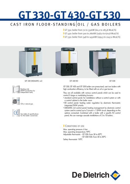
GT 330-GT 430-GT 530<br />
CAST IRON FLOOR-STANDING OIL / GAS BOILERS<br />
GT 330: boiler from 70 to 330kW (60,2 to 283,8 Mcal/h)<br />
GT 430: boiler from 300 to 780kW (258,0 to 670,8 Mcal/h)<br />
GT 530: boiler from 348 to 1450kW (299,3 to 1247,0 Mcal/h)<br />
GT 330 DIEMATIC-m3 GT 430 B3 GT 530<br />
Heating only<br />
(DHW production by<br />
independent tank)<br />
Oil or natural gas<br />
See table of specifications<br />
for <strong>the</strong> boiler concerned<br />
GT 330, GT 430 and GT 530 boilers are pressurised, cast iron boilers with<br />
high combustion efficiency, to be fitted with an oil or gas burner.<br />
They are all available with <strong>various</strong> <strong>control</strong> <strong>panels</strong> which can be used to<br />
<strong>control</strong> 2-stage or modulating burners:<br />
• standard <strong>control</strong> panel: for installations without a <strong>control</strong> system or with<br />
a <strong>control</strong> cabinet in <strong>the</strong> boiler room<br />
• B3 <strong>control</strong> panel: heating water regulation by electronic <strong>the</strong>rmostat;<br />
integrated DHW priority<br />
• DIEMATIC-m3 <strong>control</strong> panel: heating management by electronic <strong>control</strong><br />
system used to <strong>control</strong> up to 3 circuits + 1 DHW circuit, depending on <strong>the</strong><br />
options connected. Combined with a boiler with a specific K3 <strong>control</strong><br />
panel, this can manage cascade installations of 2 to 10 boilers.<br />
CONDITIONS OF USE<br />
Max. operating pressure: 6 bar<br />
Max. operating temperature: 90°C<br />
Adjustable <strong>the</strong>rmostat: - GT 330: from 30 to 85°C<br />
- GT 430/530: from 40 to 85°C<br />
Safety <strong>the</strong>rmostat: 110°C
GT 330 RANGE : presentation and specifications<br />
STRONG POINTS<br />
The GT 330 is a low temperature, cast iron boiler with an<br />
output of 70 to 330 kW, high combustion efficiency (up to<br />
93%) and **CE classification, with a pressurised combustion<br />
chamber to be fitted with an oil or gas burner:<br />
- Heating body in eutectic cast iron, which is highly resistant to<br />
corrosion, for low temperature operation modulated to 30°C.<br />
- Body design with 3-path flue gas evacuation providing<br />
advantageous acoustic properties, with a large combustion<br />
chamber to enable perfect adaptation to all types of burner,<br />
flue ways with fins including baffle plates for optimum heat<br />
exchange, available in separate sections for adaptation to<br />
boiler rooms with difficult access.<br />
- Burner and sweeping doors mounted on reversible hinges.<br />
- Enhanced, 100 mm thick glass wool insulation.<br />
- Available with <strong>various</strong> <strong>control</strong> <strong>panels</strong>, all of which can be<br />
used to <strong>control</strong> 2-stage or modulating burners: see pages 8<br />
to 12.<br />
MODELS AVAILABLE<br />
Control panel<br />
Boiler Output standard B3 DIEMATIC-m3 K3 (1)<br />
kW Mcal/h (see p 9) (see p 9) (see p 10) (see p 10)<br />
70-105 62,0-90,3 GT 334 GT 334 B3 GT 334 DIEMATIC-m3 GT 334 K3<br />
105-140 90,3-120,4 GT 335 GT 335 B3 GT 335 DIEMATIC-m3 GT 335 K3<br />
GT 330:<br />
for heating only, 140-180 120,4-154,8 GT 336 GT 336 B3 GT 336 DIEMATIC-m3 GT 336 K3<br />
DHW production by 180-230 154,8-197,8 GT 337 GT 337 B3 GT 337 DIEMATIC-m3 GT 337 K3<br />
independent tank<br />
230-280 197,8-240,8 GT 338 GT 338 B3 GT 338 DIEMATIC-m3 GT 338 K3<br />
GT_330Q0001<br />
280-330 240,8-283,8 GT 339 GT 339 B3 GT 339 DIEMATIC-m3 GT 339 K3<br />
(1) The GT 330 K3 operates only in combination with a GT 330 DIEMATIC-m3 as part of a cascade installation<br />
MAIN SPECIFICATIONS<br />
Type: Heating only<br />
Energy used: oil / gas<br />
Ref. “EC certificate”: CE 1312BR4783<br />
Combustion evacuation: chimney<br />
Min. return temperature: none<br />
Min. flow temperature: 30°C<br />
Model GT 334 335 336 337 338 339<br />
Useful output<br />
kW 70-105 105-140 140-180 180-230 230-280 280-330<br />
Mcal/h 60,2-90,3 90,3-120,4 120,4-154,8 154,8-197,8 197,8-240,8 240,8-283,8<br />
Nominal input kW 79,5-119,3 119,3-159,1 159,1-204,5 204,5-261,4 261,4-318,2 318,2-375,0<br />
Water content litres 96 116 136 156 176 196<br />
Water resistance Δt: 15 K (1) mbar 6,2 10,9 20,4 30 44,5 63,8<br />
inscribed Ø mm 377 377 377 377 377 377<br />
Combustion<br />
Length mm 571 731 891 1051 1211 1371<br />
chamber<br />
Volume m 3 0,096 0,122 0,148 0,174 0,200 0,226<br />
Flue gas circuit volume<br />
(combustion chamber + flue ways)<br />
m 3 0,163 0,206 0,249 0,292 0,335 0,378<br />
Flue gas mass domestic fuel oil kg/h 178 238 306 391 475 560<br />
flow rate (1) natural gas kg/h 187 250 334 410 499 588<br />
Flue gas temperature (1) °C 210 210 210 210 210 210<br />
Pressure in <strong>the</strong> combustion chamber<br />
for draught at <strong>the</strong> nozzle = 0 (1)<br />
mbar 0,3 0,6 1,1 1,6 2,2 2,5<br />
Number of sections 4 5 6 7 8 9<br />
Net weight (with DIEMATIC-m3 <strong>control</strong> panel) kg 612 736 846 981 1103 1230<br />
(1) At nominal stage (high boiler output), operating on domestic oil: CO2 = 13%, operating on natural gas: CO 2 = 9.0%, draught at <strong>the</strong> nozzle = 0<br />
In practice, 1 mbar is equivalent to a 10 mm water column or 100 Pascal. 1 K = 1°C<br />
2
DESCRIPTION<br />
Control panel designed for easy access to <strong>the</strong><br />
wiring (see description of <strong>the</strong> <strong>various</strong> models<br />
available on pages 9 and 10)<br />
Openings in <strong>the</strong> front and rear<br />
sections which can be used for<br />
lifting <strong>the</strong> assembled boiler body<br />
Sensor tube for housing<br />
<strong>various</strong> sensors<br />
Sweeping door mounted<br />
on reversible hinges,<br />
enabling opening to <strong>the</strong><br />
right or left<br />
Eutectic cast iron boiler body, particularly resistant to <strong>the</strong>rmal shocks and<br />
corrosion, enabling modulated low temperature operation and total<br />
shutdown between two heating periods<br />
Large wiring ducts<br />
coming out under <strong>the</strong><br />
<strong>control</strong> panel<br />
Flue nozzles<br />
with 2 cleaning<br />
hatches, directly<br />
accessible without<br />
removing <strong>the</strong> casing<br />
Insulation of <strong>the</strong><br />
sweeping door in 50 mm<br />
thick ceramic fibre<br />
6 modular baffle<br />
plates fitted to <strong>the</strong><br />
6 flue ways<br />
Large flue ways fitted<br />
with fins and modular<br />
baffle plates offering<br />
high efficiency and easy<br />
maintenance<br />
Flame display hatch<br />
Burner door mounted on<br />
reversible hinges, enabling<br />
opening to <strong>the</strong> right or left<br />
Burner door insulation<br />
in 80 to 120 mm thick<br />
ceramic fibre<br />
Heating body with<br />
3-way flue gas<br />
evacuation<br />
Large combustion chamber<br />
Complete insulation<br />
of <strong>the</strong> heating body<br />
in glass wool protected<br />
on both sides, thickness:<br />
100 mm<br />
Design of <strong>the</strong> front<br />
section particularly wellsuited<br />
to <strong>the</strong> use of low<br />
NOx burners<br />
Stoppered sludge<br />
flush opening<br />
Insulation of <strong>the</strong> front<br />
of <strong>the</strong> casing in 40 mm<br />
thick glass wool<br />
Pre-cut holes in <strong>the</strong> casing allowing<br />
<strong>the</strong> connection of <strong>the</strong> sludge flush<br />
opening<br />
Lower front panel insulation in<br />
80 mm thick glass wool<br />
GT330_F0011A<br />
Boiler shown:<br />
GT 335 DIEMATIC-m3<br />
MAIN DIMENSIONS<br />
800<br />
D<br />
4 Ø M 8 on<br />
Ø 170<br />
Ø 135<br />
Sleeve Rp 1 1/2<br />
for safety unit<br />
4 connections<br />
on Ø 200<br />
4 connections<br />
on Ø 220<br />
153<br />
(2)<br />
53<br />
L<br />
A<br />
C<br />
B<br />
Heating flow (Flange +<br />
counter flange to be welded)<br />
opening Ø 2 1/2" (*)<br />
R: threading<br />
Rp: tapped connection<br />
(*) Ø 2” optional<br />
45°<br />
H<br />
1192<br />
160<br />
=<br />
=<br />
45°<br />
137<br />
Ø 175<br />
Ø 155<br />
door thickness<br />
with insulation: 125 mm<br />
387<br />
Ø R<br />
98<br />
153<br />
718<br />
325<br />
(2)<br />
= =<br />
115<br />
137<br />
827<br />
1017<br />
103 594 103<br />
Flush opening Rp 2 1/2 (stoppered)<br />
Feet adjustable from 0 to +40 (1)<br />
P 195 105<br />
(1) If using <strong>the</strong> "adjustable feet", <strong>the</strong> whole boiler is lifted from 0 to 40 mm.<br />
(2) Lateral <strong>control</strong> panel (specify when ordering): its position on one of <strong>the</strong> lateral <strong>panels</strong> is left to <strong>the</strong> installer's discretion.<br />
Heating return (Flange +<br />
counter flange to be welded)<br />
opening Ø 2 1/2" (*)<br />
Drainage Rp 1 1/2<br />
(stoppered)<br />
GT330_F0001C<br />
GT 334 335 336 337 338 339<br />
L 991 1151 1311 1471 1631 1791<br />
P 490 650 810 970 1130 1290<br />
Ø R 180 180 180 200 200 200<br />
Control Panel A B C D H<br />
Standard 130 105 165 738 1297<br />
B3, K3 and DIEMATIC-m3 355 190 150 755 1387<br />
3
GT 430 RANGE FROM 300 TO 780 kW: presentation and specifications<br />
STRONG POINTS<br />
The GT 430 is a low temperature, cast iron boiler with an<br />
output of 300 to 780 kW, high combustion efficiency with a<br />
pressurised combustion chamber to be fitted with an oil or gas<br />
burner:<br />
- Heating body in eutectic cast iron, which is highly resistant to<br />
corrosion, for low temperature operation modulated to 40°C.<br />
- Body design with 3-path flue ways with a large combustion<br />
chamber and horizontal flue ways with fins to optimise heat<br />
exchange.<br />
- Burner and sweeping doors mounted on hinges (reversible on<br />
burner door).<br />
- Enhanced insulation in 100 mm thick glass wool and double<br />
insulation at <strong>the</strong> front.<br />
- Preset flow <strong>control</strong>ler supplied.<br />
- Cable way inside <strong>the</strong> boiler.<br />
- Available with <strong>various</strong> <strong>control</strong> <strong>panels</strong>, all of which can be<br />
used to <strong>control</strong> 2-stage or modulating burners: see pages 8<br />
to 12.<br />
- Suitable for new or existing boiler rooms: as <strong>the</strong> heating<br />
body is delivered in separate sections to be fitted to <strong>the</strong> base<br />
frame, it can be installed in boiler rooms with difficult access<br />
(heating body also available assembled on request).<br />
MODELS AVAILABLE<br />
Control panel<br />
GT_430Q0001<br />
Boiler Output standard B3 DIEMATIC-m3 K3 (1)<br />
kW Mcal/h (see p 9) (see p 9) (see p 10) (see p 10)<br />
GT 430 :<br />
for heating only,<br />
DHW production by<br />
independent tank<br />
(1) The GT 430 K3 operates only in combination with a GT 430 DIEMATIC-m3 as part of a cascade installation.<br />
300-390 258,0-335,4 GT 430-8 GT 430-8 B3 GT 430-8DIEMATIC-m3 GT 430-8 K3<br />
390-450 335,4-387,0 GT 430-9 GT 430-9 B3 GT 430-9 DIEMATIC-m3 GT 430-9 K3<br />
450-540 387,0-464,4 GT 430-10 GT 430-10B3 GT 430-10 DIEMATIC-m3 GT 430-10 K3<br />
540-600 464,4-516,0 GT 430-11 GT 430-11 B3 GT 430-11 DIEMATIC-m3 GT 430-11 K3<br />
600-670 516,0-576,2 GT 430-12 GT 430-12 B3 GT 430-12 DIEMATIC-m3 GT 430-12 K3<br />
670-720 576,2-619,2 GT 430-13 GT 430-13 B3 GT 430-13 DIEMATIC-m3 GT 430-13 K3<br />
720-780 619,2-670,8 GT 430-14 GT 430-14 B3 GT 430-14 DIEMATIC-m3 GT 430-14 K3<br />
TECHNICAL SPECIFICATIONS<br />
Type: Heating only<br />
Energy used: oil / gas<br />
Ref. “EC certificate”: CE 1312AQ0952<br />
Combustion evacuation: chimney<br />
Min. return temperature: none<br />
Min. flow temperature: 40°C<br />
Model GT 430-8 430-9 430-10 430-11 430-12 430-13 430-14<br />
Useful output<br />
kW 300-390 390-450 450-540 540-600 600-670 670-720 720-780<br />
Mcal/h 258,0-355,4 335,4-387,0 387,0-464,4 464,4-516,0 516,0-576,2 576,2-619,2 619,2-670,8<br />
Nominal input kW 333,7-443,3 443,3-511,4 511,4-613,6 613,6-681,8 681,8-761,4 761,4-818,2 818,2-886,4<br />
Water content litres 366 409 452 495 538 581 624<br />
Water resistance<br />
for Δt = 15 K (1)<br />
mbar 17 26,5 40,8 45,3 56,4 68,8 86,8<br />
inscribed Ø mm 530 530 530 530 530 530 530<br />
Combustion Width mm 638 638 638 638 638 638 638<br />
chamber Length mm 1183 1343 1503 1663 1823 1983 2143<br />
volume m 3 0,310 0,354 0,396 0,439 0,481 0,523 0,565<br />
Flue gas circuit volume m 3 0,563 0,638 0,712 0,787 0,860 0,934 1,008<br />
Flue gas mass domestic fuel oil kg/h 650 750 900 1000 1116 1200 1450<br />
flow rate (1) natural gas kg/h 700 810 972 1080 1207 1297 1405<br />
Pressure in <strong>the</strong> combustion chamber<br />
for draught at <strong>the</strong> nozzle = 0 (1))<br />
mbar 1,1 1,5 2 2,5 2,5 2,5 2,5<br />
Number of sections 8 9 10 11 12 13 14<br />
Net weight kg 1470 1650 1830 2010 2190 2370 2550<br />
(1) At nominal stage (high boiler output), operating on domestic oil: CO 2 = 13%, operating on natural gas: CO 2 = 9.0%, draught at <strong>the</strong> nozzle = 0<br />
In practice, 1 mbar is equivalent to a 10 mm water column or 100 Pascal. 1 K = 1°C<br />
4
6A<br />
0 30<br />
l<br />
DESCRIPTION<br />
Control panel designed for easy access to <strong>the</strong><br />
wiring (see description of <strong>the</strong> <strong>various</strong> models<br />
available on pages 9 and 10)<br />
Sensor tube for housing<br />
<strong>various</strong> sensors<br />
Door for sweeping <strong>the</strong><br />
flue ways mounted on<br />
hinges (1 left door and<br />
1 right door)<br />
Insulation upper front<br />
casing panel, 60 mm<br />
glass wool<br />
Insulation of <strong>the</strong><br />
sweeping doors in<br />
80 mm thick ceramic fibre<br />
Flame viewports (1 to <strong>the</strong><br />
left and 1 to <strong>the</strong> right of<br />
<strong>the</strong> combustion chamber<br />
plate)<br />
Burner door mounted on<br />
reversible hinges,<br />
enabling opening to <strong>the</strong><br />
right or left<br />
Burner door insulation in<br />
ceramic fibre, thickness:<br />
80 to 140 mm<br />
Removable combustion<br />
chamber plate<br />
Pre-cut holes in <strong>the</strong><br />
casing allowing <strong>the</strong><br />
connection of <strong>the</strong> sludge<br />
flush opening<br />
Stoppered sludge flush<br />
opening<br />
Eutectic cast iron boiler body, particularly resistant to<br />
<strong>the</strong>rmal shocks and corrosion, enabling modulated<br />
low temperature operation and total shutdown<br />
between two heating periods<br />
Connection cable with plug-in connectors<br />
for 2-stage or modulating burners prefitted<br />
in compliance with <strong>the</strong> European standard<br />
Insulation upper front<br />
casing <strong>panels</strong>, 60 mm<br />
of glass wool<br />
Modular cast iron baffle plates<br />
fittedto <strong>the</strong> 8 flue ways<br />
in <strong>the</strong> boiler<br />
Silicon seals guaranteeing<br />
that <strong>the</strong> flue gas circuit is<br />
leakproof<br />
2 large cable ways directly<br />
accessible under <strong>the</strong> top <strong>panels</strong><br />
Preset flow<br />
rate <strong>control</strong>ler<br />
Heating flow<br />
Flue nozzles<br />
with 2 cleaning<br />
hatches,<br />
directly<br />
accessible without<br />
removing <strong>the</strong> casing<br />
Large flue ways<br />
fitted with fins<br />
and modular<br />
baffle plates offering<br />
high efficiency and easy<br />
maintenance<br />
Heating body with<br />
3-way flue gas<br />
evacuation<br />
Large combustion<br />
chamber<br />
Complete insulation of<br />
<strong>the</strong> heating body in glass<br />
wool protected on both<br />
sides, thickness: 100 mm<br />
Metal frame serving<br />
as a base<br />
Rings on <strong>the</strong> frame which<br />
can be used for lifting <strong>the</strong><br />
assembled heating body<br />
Design of <strong>the</strong> front section<br />
particularly well-suited to<br />
<strong>the</strong> use of low NOx<br />
burners<br />
GT430_Q0007<br />
Boiler shown:<br />
GT 430-8 B3<br />
MAIN DIMENSIONS<br />
160<br />
=<br />
=<br />
=<br />
M =<br />
650<br />
1000<br />
=<br />
=<br />
Ø C<br />
183<br />
4<br />
1<br />
E<br />
ØA<br />
D<br />
130<br />
80<br />
140<br />
2<br />
(2)<br />
J<br />
G F<br />
718 (2)<br />
S<br />
325<br />
H<br />
147<br />
546<br />
L 22<br />
1500<br />
183 1149<br />
=<br />
638<br />
(3)<br />
140<br />
=<br />
3<br />
153<br />
1013<br />
K<br />
➀ : Heating flow Ø B (to be<br />
welded)<br />
➁: Heating return Ø B (to be<br />
welded)<br />
➂: Drainage Rp 2 (stoppered)<br />
➃: Flush opening Rp 2 1/2<br />
(stoppered)<br />
(2) Lateral <strong>control</strong> panel (specify<br />
when ordering): its position on<br />
one of <strong>the</strong> lateral <strong>panels</strong> is left<br />
to <strong>the</strong> installer's discretion<br />
(3) inscribed Ø of <strong>the</strong> combustion<br />
chamber: front section:<br />
Ø 455 mm, middle section:<br />
Ø 530 mm, Ø equivalent<br />
combustion chamber: 573 mm<br />
R: Threading<br />
Rp: Tapped connection<br />
GT430_F0001<br />
GT Ø A ext. Ø B Ø C D E J L S<br />
430-8 250 2”1/2 235 1427 1800 1505 1183<br />
whole or<br />
430-9 250 2”1/2<br />
pre-drilled<br />
235 1427 1950 1665 1343<br />
430-10 250 2”1/2 plate with 235 1427 2120 1825 1503<br />
430-11 300 3” ø of 135, 175, 254 1447 2305 1985 1663<br />
430-12 300 3” 190, 240, 250 254 1447 2465 2145 1823<br />
or 290<br />
430-13 300 3” 254 1447 2625 2305 1983<br />
on request<br />
430-14 300 3” 254 1447 2785 2465 2143<br />
Control Panel F G H K M<br />
Standard 127,5 130 105 1605 738<br />
B3, K3 and<br />
DIEMATIC-m3 113,5 355 190 1690 755<br />
5
GT 530 RANGE : presentation and specifications<br />
STRONG POINTS<br />
The GT 530 is a cast iron boiler with an output of 348 to<br />
1450 kW, high combustion efficiency and a pressurised<br />
combustion chamber to be fitted with an oil or gas burner:<br />
- Heating body in eutectic cast iron, which is highly resistant to<br />
corrosion, for low temperature operation modulated to 40°C.<br />
- Front section with damp walls increasing <strong>the</strong> heat exchange<br />
surface in <strong>the</strong> combustion chamber and reducing NOx<br />
emissions.<br />
- 4-path combustion products circuit in parallel series for a loss<br />
of load in <strong>the</strong> flue gas circuit inferior to traditional pressurised<br />
boilers.<br />
- Burner door on reversible hinge, maintenance access from<br />
<strong>the</strong> front with fast opening system.<br />
MODELS AVAILABLE<br />
- Enhanced insulation of 100 mm to 120 mm in <strong>the</strong> upper<br />
section.<br />
- Access way on <strong>the</strong> top central section of <strong>the</strong> boiler.<br />
- Preset flow rate <strong>control</strong>ler supplied.<br />
- Cable ways inside <strong>the</strong> boiler.<br />
- Available with <strong>various</strong> <strong>control</strong> <strong>panels</strong>, all of which can be<br />
used to <strong>control</strong> 2-stage or modulating burners: see pages<br />
8 to 12.<br />
- Suitable for new or existing boiler rooms: as <strong>the</strong> heating<br />
body is delivered in separate sections, it can be installed in<br />
boiler rooms with difficult access; heating body also available<br />
assembled on request.<br />
Control panel<br />
GT_530Q0001<br />
Boiler Output<br />
kW Mcal/h<br />
standard<br />
(see p 9)<br />
B3<br />
(see p 9)<br />
DIEMATIC-m3<br />
(see p 10)<br />
K3 (1)<br />
(see p 10)<br />
348-406 299,3-349,2 GT 530-7 GT 530-7 B3 GT 530-7DIEMATIC-m3 GT 530-8 K3<br />
406-464 349,2-399,0 GT 530-8 GT 530-8 B3 GT 530-8DIEMATIC-m3 GT 530-8 K3<br />
GT 530 :<br />
for heating only,<br />
DHW production by<br />
independent tank<br />
(1) The GT 530 K3 operates only in combination with a GT 530 DIEMATIC-m3 as part of a cascade installation.<br />
464-522 399,0-448,9 GT 530-9 GT 530-9 B3 GT 530-9 DIEMATIC-m3 GT 530-9 K3<br />
522-580 448,9-498,8 GT 530-10 GT 530-10B3 GT 530-10 DIEMATIC-m3 GT 530-10 K3<br />
580-638 498,8-548,7 GT 530-11 GT 530-11 B3 GT 530-11 DIEMATIC-m3 GT 530-11 K3<br />
638-696 548,7-598,6 GT 530-12 GT 530-12 B3 GT 530-12 DIEMATIC-m3 GT 530-12 K3<br />
696-754 598,6-648,4 GT 530-13 GT 530-13 B3 GT 530-13 DIEMATIC-m3 GT 530-13 K3<br />
754-812 648,4-698,3 GT 530-14 GT 530-14 B3 GT 530-14 DIEMATIC-m3 GT 530-14 K3<br />
812-870 698,3-748,2 GT 530-15 GT 530-15 B3 GT 530-15 DIEMATIC-m3 GT 530-15 K3<br />
870-928 748,2-798,1 GT 530-16 GT 530-16 B3 GT 530-16 DIEMATIC-m3 GT 530-16 K3<br />
928-986 798,1-848,0 GT 530-17 GT 530-17 B3 GT 530-17 DIEMATIC-m3 GT 530-17 K3<br />
986-1044 848,0-897,8 GT 530-18 GT 530-18 B3 GT 530-18 DIEMATIC-m3 GT 530-18 K3<br />
1044-1102 897,8-947,7 GT 530-19 GT 530-19 B3 GT 530-19 DIEMATIC-m3 GT 530-19 K3<br />
1102-1160 947,7-997,6 GT 530-20 GT 530-20 B3 GT 530-20 DIEMATIC-m3 GT 530-20 K3<br />
1160-1218 997,6-10475 GT 530-21 GT 530-21 B3 GT 530-21 DIEMATIC-m3 GT 530-21 K3<br />
1218-1276 1047,5-1097,4 GT 530-22 GT 530-22 B3 GT 530-22 DIEMATIC-m3 GT 530-22 K3<br />
1276-1334 1097,4-1147,2 GT 530-23 GT 530-23 B3 GT 530-23 DIEMATIC-m3 GT 530-23 K3<br />
1334-1400 1147,2-1204,0 GT 530-24 GT 530-24 B3 GT 530-24 DIEMATIC-m3 GT 530-24 K3<br />
14001450 1204,0-1247,0 GT 530-25 GT 530-25 B3 GT 530-25 DIEMATIC-m3 GT 530-25 K3<br />
TECHNICAL SPECIFICATIONS<br />
Type: Heating only<br />
Energy used: oil / gas<br />
Ref. “EC certificate”: CE 1312AQ0954<br />
Combustion evacuation: chimney<br />
Min. return temperature: none<br />
Min. flow temperature: 40°C<br />
Model GT530- 7 8 9 10 11 12 13 14 15 16 17 18 19 20 21 22 23 24 25<br />
348- 406- 464- 522- 580- 638- 696- 754- 812- 870- 928- 986- 1044- 1102- 1160- 1218- 1276- 1334- 1400-<br />
kW<br />
406 464 522 580 638 696 754 812 870 928 986 1044 1102 1160 1218 1276 1334 1400 1450<br />
Useful output<br />
Mcal/h 299,3- 349,2- 399,0- 448,9- 498,8- 548,7- 598,6 648,4- 698,3- 748,2- 798,1- 848,0- 897,8- 947,7- 997,6- 1047,5- 1097,4- 1147,2- 1204,0<br />
349,2 399,0 448,9 498,8 548,7 598,6 648,4 698,3 748,2 798,1 848,0 897,8 947,7 997,6 1047,5 1097,4 1147,2 1204,0 1247,0<br />
Nominal input kW 387- 451- 516- 580- 644- 709- 773- 838- 902- 967- 1031- 1096- 1160- 1224- 1289- 1358- 1418- 1482- 1547-<br />
451 516 580 644 709 773 838 902 967 1031 1096 1160 1224 1289 1358 1418 1482 1547 1611<br />
Water content litres 389 427 465 503 541 579 617 655 693 731 769 807 845 905 943 981 1019 1057 1095<br />
Water resistance for Δt: 15 K (1) mbar 8 9,9 12,6 15,5 18,7 22,4 25,8 30,0 34,7 11,7 13,5 14,0 18,5 21,5 24,0 26,5 29,0 32,0 35,0<br />
Combustion width 683 mm, l mm 706 817 928 1039 1150 1261 1372 1483 1594 1705 1816 1927 2038 2189 2300 2411 2522 2633 2744<br />
chamber volume m 3 0,28 0,32 0,36 0,40 0,45 0,49 0,53 0,57 0,61 0,65 0,70 0,74 0,78 0,84 0,88 0,92 0,96 1,00 1,05<br />
Flue gas domestic fuel oil kg/h 620 700 770 850 920 1000 1070 1150 1220 1300 1370 1450 1520 1600 1670 1750 1820 1900 1970<br />
mass flow rate (1) gas kg/h 650 730 810 890 970 1040 1120 1200 1280 1360 1440 1520 1590 1670 1750 1830 1910 1990 2070<br />
Combustion chamber pressure (1) mbar 1,7 1,75 1,8 1,9 2,0 2,1 2,2 2,3 2,4 2,5 2,6 2,7 2,85 3,0 3,1 3,2 3,3 3,4 3,5<br />
Net weight kg 1852 2046 2237 2412 2601 2810 3000 3171 3364 3561 3756 3955 4124 4343 4538 4734 4930 5107 5297<br />
(1) At nominal stage, CO 2 : 13% with oil and 9.5% with natural gas, draught at <strong>the</strong> nozzle = 0.<br />
6
6A<br />
0 30<br />
l<br />
DESCRIPTION<br />
Sensor tube for housing <strong>various</strong><br />
sensors<br />
Large wiring ducts coming out<br />
under <strong>the</strong> <strong>control</strong> panel<br />
Access way facilitating accessibility to<br />
<strong>various</strong> components in <strong>the</strong> boiler room<br />
and facilitating boiler maintenance<br />
Removable insulation modules in<br />
glass wool protected on both<br />
sides, thickness: 120 mm<br />
Heating flow<br />
Sweeping hatches for <strong>the</strong><br />
vertical plates with “unlosable”<br />
holding screws<br />
Control panel:<br />
description see p. 9<br />
and 10<br />
Sweeping hatches for<br />
<strong>the</strong> upper flue ways<br />
Flame viewport<br />
Burner door mounted on<br />
reversible hinge, enabling<br />
opening to <strong>the</strong> right or<br />
left<br />
Burner door insulation<br />
in ceramic fibre<br />
Preset flow rate<br />
<strong>control</strong>ler<br />
Flue gas nozzle<br />
Upper flue ways fitted<br />
with fins and modular<br />
baffle plates<br />
Exchange surface<br />
maximised by moulded<br />
profiles<br />
4-path flue gas circuit<br />
in series/parallel<br />
Heating<br />
return<br />
Sweeping hatch for <strong>the</strong><br />
flue gas box<br />
Sweeping hatches<br />
for <strong>the</strong> lower flue ways<br />
Silicon seal guaranteeing<br />
that <strong>the</strong> flue gas circuit is<br />
leakproof<br />
Stoppered sludge<br />
flush opening<br />
Metal frame serving as a<br />
base fitted with rings<br />
which can be used for<br />
lifting <strong>the</strong> assembled<br />
heating body<br />
Pre-cut holes in <strong>the</strong><br />
casing allowing <strong>the</strong><br />
connection to <strong>the</strong> sludge<br />
flush opening<br />
Connection cable with plug-in connectors for 2-stage or<br />
modulating burners prefitted in compliance with <strong>the</strong> European standard<br />
MAIN DIMENSIONS<br />
S<br />
1566<br />
160<br />
=<br />
Q<br />
616<br />
420<br />
370<br />
=<br />
496 Ø F<br />
C<br />
543<br />
1080<br />
815<br />
Ø E<br />
200<br />
1172<br />
H M<br />
B<br />
G<br />
L<br />
(1) The burner shaft is marked with an arrow. Optional drilling of <strong>the</strong> burner door on request<br />
and without additional cost in diameters of 165, 186, 210, 240 or 290 mm.<br />
(2) Lateral <strong>control</strong> panel (specify when ordering): its position on one of <strong>the</strong> lateral <strong>panels</strong> is left<br />
to <strong>the</strong> installer's discretion.<br />
Ø E<br />
D<br />
K<br />
4<br />
741<br />
(2)<br />
5<br />
T<br />
U<br />
A<br />
718<br />
(1)<br />
325<br />
(2)<br />
Eutectic cast iron heating body, particularly resistant to<br />
<strong>the</strong>rmal shocks and corrosion, enabling modulated<br />
low temperature operation and total shutdown<br />
between two heating periods<br />
Dampened front section (improvement of efficiency,<br />
reduction of NOx emissions)<br />
Insulation: front casing <strong>panels</strong> in glass wool<br />
protected on both sides, thickness: 100 mm<br />
GT530_Q0008<br />
Boiler shown:<br />
GT 530-10<br />
P<br />
R<br />
17,5<br />
240<br />
791<br />
500<br />
maxi<br />
565<br />
GT530_F0001<br />
700<br />
maxi<br />
3<br />
610<br />
1<br />
Complete insulation of <strong>the</strong> boiler body<br />
in glass wool protected on both sides,<br />
thickness: 100 mm<br />
2<br />
➀: Heating flow Ø E (to be<br />
welded)<br />
➁: Heating return Ø E (to be<br />
welded)<br />
➂: Drainage Rp 3/4<br />
➃: Flow rate detector<br />
➄: Min. height for<br />
maintenance = 850 mm<br />
* Full plate to be cut out<br />
Max. cut-out 500 x 700<br />
mm, delivered without<br />
connection nozzle<br />
** length required for<br />
clearance of <strong>the</strong><br />
equidistribution water pipe<br />
équirépartiteur d’eau<br />
*** Dimension corresponding<br />
to <strong>the</strong> extremity of <strong>the</strong><br />
chimney connection (with<br />
nozzle, height 100 mm)<br />
R: Threading<br />
Rp: Tapped connection<br />
Control Panel P Q R S<br />
Standard 130 738 20 1670<br />
B3, K3 and DIEMATIC-m3 355 755 175 1760<br />
Boiler GT530- 7 8 9 10 11 12 13 14 15 16 17 18 19 20 21 22 23 24 25<br />
A standard <strong>control</strong> panel 1606 1717 1828 1939 2050 2161 2272 2383 2494 2605 2716 2862 2973 3124 3235 3346 3457 3568 3679<br />
B3, K3 and DIEMATIC-m3 <strong>control</strong> <strong>panels</strong> 1761 1872 1983 2094 2205 2316 2427 2538 2649 2760 2871 3017 3128 3279 3390 3501 3612 3723 3834<br />
B 967 1078 1078 1300 1300 1522 1522 1744 1744 1966 1966 2188 2188 2450 2450 2672 2672 2894 2894<br />
C 1488 1488 1488 1488 1488 1488 1488 1488 1488 1488 1488 1504 1504 1504 1504 1504 1504 1504 1504<br />
D 240 211 212 233 234 255 256 217 188 189 210 236 257 208 209 230 231 252 253<br />
ø E (to be welded) 139,7 139,7 139,7 139,7 139,7 139,7 139,7 139,7 139,7 139,7 139,7 159 159 159 159 159 159 159 159<br />
ø F 300 300 300 350 350 350 350 400 400 400 400 400 400 400 * * * * *<br />
G - - - - - - - - 150 150 370 370 370 650 650 650 980 980 980<br />
H 21 -8 -7 14 15 36 37 -2 -31 -30 -9 -8 13 -36 -35 -14 -13 8 9<br />
K** 33 4 5 26 27 48 49 10 -19 -18 3 4 25 -24 -23 -2 -1 20 21<br />
L 1305 1445 1555 1645 1755 1845 1955 2105 2245 2355 2445 2555 2645 2845 2955 3045 3155 3245 3355<br />
M 248 265 319 243 297 221 275 259 324 269 321 265 299 269 324 269 324 249 303<br />
T 706 817 928 1039 1150 1261 1372 1483 1594 1705 1816 1927 2038 2189 2300 2411 2522 2633 2744<br />
U 1355 1466 1577 1688 1799 1910 2021 2132 2243 2354 2465 2576 2687 2838 2949 3060 3171 3282 3393<br />
7
6A<br />
6A<br />
6A<br />
6A<br />
6A<br />
0<br />
l<br />
TEST<br />
STB<br />
6A<br />
0<br />
l<br />
2<br />
4<br />
3<br />
1<br />
5<br />
6<br />
7<br />
8<br />
6<br />
5<br />
7<br />
4<br />
8<br />
3<br />
9<br />
0 30<br />
l<br />
0 30<br />
l<br />
0 30<br />
l<br />
0 30<br />
l<br />
30<br />
TS<br />
N L<br />
TS<br />
N L<br />
TS<br />
N L<br />
TS<br />
N L<br />
TS<br />
N L<br />
TS<br />
N L<br />
TS<br />
N L<br />
TS<br />
N L<br />
TS<br />
N L<br />
TS<br />
N L<br />
TS<br />
N L<br />
TS<br />
N L<br />
TS<br />
N L<br />
TS<br />
N L<br />
TS<br />
N L<br />
TS<br />
N L<br />
TS<br />
N L<br />
TS<br />
N L<br />
CHOICE OF CONTROL PANEL<br />
The <strong>control</strong> panel is chosen according to <strong>the</strong> installation to be constructed:<br />
INSTALLATION WITH A SINGLE BOILER<br />
3 types of <strong>control</strong> panel are possible:<br />
Standard<br />
for installations without <strong>control</strong> system or<br />
for ones with a <strong>control</strong> cabinet in <strong>the</strong> boiler room<br />
88<br />
for <strong>control</strong>ling a single direct circuit<br />
B3<br />
GT 330...<br />
GT 430...<br />
ou<br />
GT 530...<br />
DIEMATIC-m3<br />
for <strong>control</strong>ling<br />
a direct circuit<br />
(without<br />
mixing valve)<br />
or depending on <strong>the</strong> optional equipment connected, for:<br />
A single<br />
circuit with<br />
mixing valve<br />
2 circuits, one<br />
of which with<br />
mixing valve<br />
2 circuits, each<br />
with a mixing<br />
valve<br />
3 circuits, 2 of which with<br />
mixing valve<br />
3 circuits, each with a<br />
mixing valve<br />
M<br />
M<br />
M<br />
M<br />
M<br />
M<br />
M<br />
M<br />
M<br />
option :<br />
1 flow<br />
sensor<br />
AD 199<br />
+<br />
1 flow<br />
sensor<br />
AD 199<br />
1 PCB FM 48 1 PCB FM 48 2 PCBs FM 48<br />
+<br />
1 flow<br />
sensor<br />
AD 199<br />
2 PCBs FM 48<br />
CASCADE INSTALLATION OF 2 TO 10 BOILERS<br />
2 types of <strong>control</strong> panel are required: 1 DIEMATIC-m3 <strong>control</strong> panel for <strong>the</strong> first boiler in <strong>the</strong> cascade (master boiler) and 1 K3 <strong>control</strong><br />
panel for each of <strong>the</strong> slave boilers.<br />
DIEMATIC-m3<br />
for <strong>control</strong>ling<br />
a direct circuit<br />
(without<br />
mixing valve)<br />
or depending on <strong>the</strong> optional equipment connected, for:<br />
A single<br />
circuit with<br />
mixing valve<br />
2 circuits, one of<br />
which with mixing<br />
valve<br />
2 circuits, each with<br />
a mixing valve<br />
3 circuits, 2 of which with<br />
mixing valve<br />
3 circuits, each with a<br />
mixing valve<br />
M<br />
M<br />
M<br />
M<br />
M<br />
M<br />
M<br />
M<br />
M<br />
Boiler 1<br />
(master)<br />
BUS<br />
option :<br />
1 flow<br />
sensor<br />
AD 199<br />
+<br />
1 flow<br />
sensor<br />
AD 199<br />
1 PCB FM 48 1 PCB FM 48 2 PCBs FM 48<br />
+<br />
1 flow<br />
sensor<br />
AD 199<br />
2 PCBs FM 48<br />
K3<br />
in addition, for each of <strong>the</strong> slave boilers, depending on <strong>the</strong> optional equipment connected, for:<br />
1 circuit with mixing valve<br />
2 circuits with mixing valve<br />
3 circuits with mixing valve<br />
M<br />
M<br />
M<br />
M<br />
M<br />
M<br />
Boiler 2<br />
BUS<br />
option :<br />
1 Package AD 220<br />
1 Package AD 220<br />
1 Package AD 220<br />
+ +<br />
1 PCB<br />
FM 48<br />
2 PCBs<br />
FM 48<br />
K3<br />
up to 10 boilers: for each additional slave boiler connected, it is possible to <strong>control</strong> up to 3 additional<br />
valve circuits<br />
GT330_F0018A<br />
8<br />
DHW PRODUCTION<br />
The B3 and DIEMATIC-m3 <strong>control</strong> <strong>panels</strong> include <strong>the</strong> “DHW priority” function and can <strong>the</strong>refore be complemented with 1 DHW sensor –<br />
package AD 212 – for <strong>control</strong>ling an independent hot water tank.
THE VARIOUS CONTROL PANELS<br />
STANDARD CONTROL PANEL<br />
GT 330, GT 430 and GT 530 boilers are delivered with a<br />
standard <strong>control</strong> panel for <strong>control</strong>ling 1- or 2-stage burners.<br />
These configurations are recommended for heating installations<br />
without a <strong>control</strong> system or with a <strong>control</strong> cabinet in <strong>the</strong> boiler<br />
room.<br />
Safety <strong>the</strong>rmostat<br />
(110°C) with manual<br />
reset<br />
Thermometer<br />
Timed 10A<br />
circuit breaker<br />
Standard <strong>control</strong> panel option<br />
Safety <strong>the</strong>rmostat<br />
test button<br />
On/Off switch<br />
1st stage <strong>the</strong>rmostat<br />
- GT 330: adjustable from 30 to 85°C<br />
- GT 430-530: adjustable from 40 to<br />
85°C<br />
Flue gas <strong>the</strong>rmometer - Package BP 28<br />
This is clipped into <strong>the</strong> position provided on <strong>the</strong><br />
<strong>control</strong> panel.<br />
Position flue gas<br />
<strong>the</strong>rmometer (optional)<br />
2nd stage <strong>the</strong>rmostat<br />
- GT 330: adjustable from 30 to 85°C GT330_Q0006A<br />
- GT 430-530: adjustable from 40 to<br />
85°C<br />
8666Q170<br />
B3 BASIC CONTROL PANEL<br />
The B3 <strong>control</strong> panel fitted to GT 330 B3, GT 430 B3 and<br />
GT 530 B3 boilers is used to <strong>control</strong> 1- or 2-stage burners. It<br />
includes <strong>control</strong> and safety devices used to operate <strong>the</strong><br />
installation by regulating its temperature with <strong>the</strong> boiler<br />
Pump shutdown<br />
switch<br />
Electronic <strong>the</strong>rmostat regulating<br />
<strong>the</strong> DHW storage temp., setting<br />
from 10 to 80 °C<br />
Boiler/DHW<br />
temperature<br />
display<br />
<strong>the</strong>rmostat. It is fitted as standard with domestic hot water<br />
production priority (optional DHW sensor: package AD212)<br />
when <strong>the</strong> GT… B3 is connected to an independent tank.<br />
Electronic boiler <strong>the</strong>rmostat:<br />
- GT 330: adjustable from 30 to 85°C<br />
- GT 430-530: adjustable from 40 to 85°C<br />
Timed 10A<br />
circuit breaker<br />
Burner alarm light<br />
Safety <strong>the</strong>rmostat<br />
(110°C) with manual<br />
reset<br />
Position hour<br />
run meters<br />
(optional)<br />
3-position switch:<br />
- Heating + DHW<br />
- DHW<br />
-STB TEST: safety <strong>the</strong>rmostat test<br />
On/Off<br />
switch<br />
1st/2nd stage<br />
selection<br />
switch<br />
DHW<br />
temperature<br />
display light<br />
Boiler temperature<br />
display light<br />
Position flue gas<br />
<strong>the</strong>rmometer (optional)<br />
GT330_Q0008A<br />
B3 <strong>control</strong> panel options<br />
Flue gas <strong>the</strong>rmometer - Package BP 28<br />
This is clipped into <strong>the</strong> position provided on <strong>the</strong><br />
<strong>control</strong> panel.<br />
8666Q170<br />
8199Q059<br />
8518Q022<br />
Hour run meter - Package BG 40<br />
Used to display <strong>the</strong> number of hours of burner<br />
operation. If using a 2-stage burner, 2 hour run<br />
meters displaying <strong>the</strong> number of hours of operation<br />
Domestic hot water sensor - Package AD 212<br />
This is used to regulate <strong>the</strong> boiler with domestic hot<br />
water temperature priority.<br />
for each stage are required. Can be clipped into <strong>the</strong><br />
positions provided in <strong>the</strong> <strong>control</strong> panel.<br />
Colis AD 200<br />
8666Q120<br />
Programmable wire-<strong>control</strong>led room <strong>the</strong>rmostat - Package AD 137<br />
Programmable wireless room <strong>the</strong>rmostat - Package AD 200<br />
Non-programmable room <strong>the</strong>rmostat - Package AD 140<br />
These <strong>the</strong>rmostats handle <strong>the</strong> regulation or weekly AD 137 and AD 200) by activating <strong>the</strong> burner.<br />
heating programme on a direct circuit (models<br />
9
0<br />
0<br />
THE VARIOUS CONTROL PANELS<br />
DIEMATIC-M3 AND K3 CONTROL PANELS<br />
The DIEMATIC-m3 <strong>control</strong> panel is a very advanced <strong>control</strong><br />
panel, which includes electronic programmable regulation as<br />
standard to modulate <strong>the</strong> boiler temperature by activating <strong>the</strong><br />
burner (1, 2 stages or modulating) according to <strong>the</strong> outside<br />
temperature and <strong>the</strong> room temperature if a CDI 2 or CDR 2<br />
interactive remote <strong>control</strong> is connected (optional)<br />
As standard, DIEMATIC-m3 is capable of automatically<br />
operating a central heating installation with a direct circuit<br />
without mixing valve or a circuit with mixing valve (<strong>the</strong> flow<br />
sensor – package AD 199 – must be ordered separately,<br />
however).<br />
By connecting ano<strong>the</strong>r 1 or 2 “PCB + sensor for 1 valve circuit”<br />
options (package FM 48), it is <strong>the</strong>refore possible to <strong>control</strong> up<br />
to 3 circuits with mixing valve and each of <strong>the</strong>se circuits can be<br />
fitted with a CDI 2 or CDR 2 remote <strong>control</strong> (optional)<br />
Connection of a domestic hot water sensor enables <strong>the</strong><br />
programming and regulation of a DHW circuit by activating a<br />
<strong>control</strong> system on <strong>the</strong> load pump; DHW looping can be<br />
handled thanks to <strong>the</strong> auxiliary contact which includes its own<br />
programming.<br />
DIEMATIC-m3 also provides antifreeze protection for <strong>the</strong><br />
installation and <strong>the</strong> living space if <strong>the</strong> home is unoccupied and<br />
can be programmed 1 year in advance for a period of up to<br />
99 days.<br />
Fur<strong>the</strong>rmore, <strong>the</strong> <strong>control</strong> system includes an “anti-legionella”<br />
protection option.<br />
Moreover, in <strong>the</strong> context of larger installations, it is<br />
possible to connect from 2 to 10 boilers in cascade: only <strong>the</strong><br />
first of <strong>the</strong>se boilers will be fitted with <strong>the</strong> DIEMATIC-m3<br />
<strong>control</strong> panel, whilst <strong>the</strong> o<strong>the</strong>rs will be fitted with <strong>the</strong> K3 <strong>control</strong><br />
panel. Each of <strong>the</strong>se GT 330 K3, GT 430 K3 or GT 530 K3<br />
boilers can in turn be complemented with PCBs (AD 220 + 1<br />
or 2 x FM 48) for <strong>control</strong>ling up to 3 circuits with mixing valve<br />
(see p. 5) with or without CDI 2 or CDR 2 remote <strong>control</strong>.<br />
DIEMATIC-m3 <strong>control</strong> panel<br />
Pump shutdown<br />
switch<br />
Boiler <strong>the</strong>rmostat:<br />
- GT 330: adjustable from 30 to 85°C<br />
- GT 430/530: adjustable from<br />
40 to 85°C<br />
DIEMATIC-m3<br />
<strong>control</strong> module<br />
Boiler<br />
<strong>the</strong>rmometer<br />
Timed 10A<br />
circuit breaker<br />
Burner alarm light<br />
Safety <strong>the</strong>rmostat<br />
(110 °C) with<br />
manual reset<br />
Connector<br />
for programming<br />
unit<br />
3-position switch:<br />
- auto<br />
- manual<br />
- safety <strong>the</strong>rmostat test<br />
On/Off switch<br />
1 st /2 nd stage<br />
selection switch<br />
Boiler heating curve<br />
GT330_Q0009A<br />
DIEMATIC-m3 <strong>control</strong> module:<br />
The <strong>control</strong> module integrated into <strong>the</strong> DIEMATIC-m3 <strong>control</strong><br />
panel enables <strong>the</strong> installer to set <strong>the</strong> parameters for <strong>the</strong> entire<br />
heating installation, whatever its degree of complexity. It can<br />
be used to manage equally well:<br />
- a GT 330 DIEMATIC-m3, GT 430 DIEMATIC-m3 or GT 530<br />
DIEMATIC-m3 boiler installed on its own,<br />
- or a cascade of boilers in which only <strong>the</strong> first will be fitted<br />
with <strong>the</strong> DIEMATIC-m3 <strong>control</strong> panel, all <strong>the</strong> o<strong>the</strong>rs being fitted<br />
with <strong>the</strong> K3 <strong>control</strong> panel.<br />
It also enables <strong>the</strong> user to programme each of <strong>the</strong> circuits in<br />
<strong>the</strong> installation independently, including those connected to <strong>the</strong><br />
slave boilers with K3 <strong>control</strong> panel in a cascade installation. It<br />
makes it possible to select <strong>the</strong> appropriate operating mode for<br />
heating (Auto mode depending on programming, “Day”,<br />
“Night” or “Antifreeze” temperature mode, whe<strong>the</strong>r temporary<br />
or permanent), and for domestic hot water production (Auto,<br />
temporary or permanent forced load). It also makes it possible<br />
to access <strong>the</strong> <strong>various</strong> settings parameters and measurements in<br />
<strong>the</strong> installation to modify <strong>the</strong>m or simply consult <strong>the</strong>m, etc.<br />
SUNDAY<br />
SUNDAY<br />
Control module, flap closed<br />
SUNDAY<br />
SUNDAY<br />
Control module, flap open<br />
GT330_F0017<br />
10
TS<br />
3 4<br />
2<br />
THE VARIOUS CONTROL PANELS<br />
K3 <strong>control</strong> panel<br />
Pump shutdown switch<br />
1 st /2 nd stage<br />
selection switch<br />
Boiler<br />
<strong>the</strong>rmometer<br />
Timed 10A<br />
circuit breaker<br />
Burner alarm light<br />
Safety<br />
<strong>the</strong>rmostat (110°C)<br />
with manual reset<br />
Connector for<br />
programming unit<br />
3-position switch:<br />
- auto<br />
- manual<br />
- safety <strong>the</strong>rmostat test<br />
On/Off switch<br />
Boiler <strong>the</strong>rmostat:<br />
- GT 330: adjustable from 30 to 85°C<br />
- GT 430/530: adjustable from 40 to 85°C<br />
GT330_Q0007A<br />
NB: All of <strong>the</strong> settings and measurement parameters on each of<br />
<strong>the</strong> boilers in cascades fitted with <strong>the</strong> K3 <strong>control</strong> panel can be<br />
accessed on <strong>the</strong> DIEMATIC-m3 <strong>control</strong> panel on <strong>the</strong> master boiler<br />
DIEMATIC-m3 and K3 <strong>control</strong> panel options<br />
GT220_Q0001<br />
Flow sensor downstream of <strong>the</strong> valve - Package AD 199<br />
This sensor is required in installations which have connect <strong>the</strong> first of <strong>the</strong>se circuits to <strong>the</strong> DIEMATICm3<br />
<strong>control</strong> panel – see page only circuits with mixing valve (no direct circuit) to<br />
8.<br />
8575Q036<br />
PCB + sensor for 1 mixing valve - Package FM 48<br />
This is used to <strong>control</strong> a mixing valve with a<br />
2-direction electro<strong>the</strong>rmal or electromechanical<br />
motor. The valve circuit and its circulating pump<br />
can be programmed independently.<br />
Notes:<br />
- In addition to <strong>the</strong> sensor AD 199 for <strong>the</strong> first<br />
valve circuit, DIEMATIC-m3 can be fitted with 1<br />
or 2 additional “PCB + sensor for 1 mixing valve”<br />
option(s) – see p. 8.<br />
- K3 can also be fitted with <strong>the</strong>se PCBs in addition<br />
to <strong>the</strong> AD 220 PCB required for <strong>the</strong> first valve<br />
circuit connected to a GT… K3.<br />
8518Q022<br />
Domestic hot water sensor - Package AD 212<br />
This is used for priority temperature regulation and<br />
programming domestic hot water production<br />
It handles <strong>the</strong> boiler sensor function for <strong>the</strong><br />
GT… K3 in a modulating cascade installation.<br />
N L N L<br />
N L N L N L<br />
1 2 2 1 2 1 2 1 2 1 2 1 2 1 2 1 2 1 2 1 2 1 2 1 1<br />
GT330_F0004<br />
Relay PCB + sensors for <strong>the</strong> first valve circuit on a GT… K3 - Package AD 220<br />
This PCB is required to connect <strong>the</strong> first valve circuit NB: 1 “relay PCB + sensors for first valve circuit”<br />
with mixing valve to a GT… boiler with K3 per GT… K3 boiler can be connected.<br />
<strong>control</strong> panel as part of a cascade installation.<br />
Flue gas sensor - Package FM 47<br />
This can be fitted to a GT… DIEMATIC-m3 boiler<br />
or, in cascade installations, to each of <strong>the</strong> GT…<br />
DIEMATIC-m3 or GT… K3 boilers in this cascade.<br />
It enables <strong>the</strong> user to read <strong>the</strong> flue gas<br />
temperature and thus check <strong>the</strong> cleanliness of <strong>the</strong><br />
heat exchange surfaces in <strong>the</strong> boiler body.<br />
8575Q048<br />
11
THE VARIOUS CONTROL PANELS<br />
DIEMATIC-m3 and K3 <strong>control</strong> panel options (contd.)<br />
8575Q026<br />
CDI 2 interactive remote <strong>control</strong> – Package FM 51<br />
CDR 2 interactive “radio” remote <strong>control</strong> (with radio transmitter) – Package FM 161<br />
CDR 2 “radio” remote <strong>control</strong> module (without transmitter) – Package FM 162<br />
These are used to override all instructions from <strong>the</strong><br />
DIEMATIC-m3 or K3 <strong>control</strong> panel from <strong>the</strong> room<br />
in which <strong>the</strong>y are installed. In addition, <strong>the</strong>y enable<br />
<strong>the</strong> heating <strong>control</strong> to adapt itself to <strong>the</strong> circuit<br />
concerned (one CDI 2 or CDR 2 per circuit). In <strong>the</strong><br />
case of <strong>the</strong> CDR 2, data are transmitted by radio<br />
waves from <strong>the</strong>ir point of installation to <strong>the</strong><br />
transmitter/receiver box located close to <strong>the</strong> boiler.<br />
8575Q037<br />
Simplified remote <strong>control</strong> with room sensor – Package FM 52<br />
The connection of a simplified remote <strong>control</strong> is temperature override (±3.5°C). It is also used to<br />
used to override certain instructions from <strong>the</strong> enable <strong>the</strong> self-adaptability of <strong>the</strong> heating curve<br />
DIEMATIC 3 or K3 <strong>control</strong> panel from <strong>the</strong> room in for <strong>the</strong> circuit concerned (1 simplified remote<br />
which it is installed: programme override<br />
<strong>control</strong> per circuit).<br />
(permanent comfort or low) and set room<br />
BUS connecting cable (length 12 m) – Package AD 134<br />
This cable is used to make <strong>the</strong> connection between on a remote management network or a DIEMATIC<br />
<strong>the</strong> DIEMATIC-m3 <strong>control</strong> panel and <strong>the</strong> transmitter VM <strong>control</strong> system.<br />
8227Q020<br />
BUS connecting cable (length 40 m) – Package DB 119<br />
This armoured cable is intended to replace <strong>the</strong> BUS <strong>the</strong> 12 m BUS cable (package AD 134) presented<br />
cable delivered with <strong>the</strong> GT… K3 (length 12 m) or above, when <strong>the</strong>se turn out to be too short.<br />
8199Q063<br />
8801Q018<br />
Dip sensor with sensor tube – Package AD 218<br />
This dip sensor (NTC 147) is delivered with an IP54<br />
junction box and a 1/2” sensor tube, length under<br />
head 120 mm. It is used instead of <strong>the</strong> attachable<br />
sensors provided with <strong>the</strong> valve PCB options. It can<br />
also be used on <strong>the</strong> decoupling tank in <strong>the</strong> context<br />
of a cascade installation, for example.<br />
DIEMATIC VM <strong>control</strong> system – Package AD 120<br />
With <strong>the</strong> addition of a BUS cable, <strong>the</strong> DIEMATICm3<br />
<strong>control</strong> panel can be completed with one or<br />
more DIEMATIC VM modules (up to 20), making it<br />
possible to <strong>control</strong> 2 additional hydraulic circuits<br />
each<br />
Each of <strong>the</strong>se circuits may be ei<strong>the</strong>r:<br />
- a heating circuit with motorised 2-way valve<br />
- or a domestic hot water preparation circuit<br />
- or an auxiliary circuit. See specific instruction<br />
booklet for <strong>the</strong> “DIEMATIC VM Control System”.<br />
12
BOILER OPTIONS<br />
OPTIONS SPECIFIC TO GT 330<br />
Recirculation kit up to 150 kW – Package FD 36 (for GT 334-335 and 336)<br />
This kit, which includes a pump and two gate in installations with a single boiler with flow/return<br />
valves, is fitted to <strong>the</strong> outlet and return flanges to collector.<br />
<strong>the</strong> rear of <strong>the</strong> boiler, ei<strong>the</strong>r right or left. It is used<br />
8553Q007<br />
Recirculation kit from 150 to 330 kW – Package FD 46 (for GT 337-338-339)<br />
This kit, which includes a pump and two gate in installations with a single boiler with flow/return<br />
valves, is fitted to <strong>the</strong> outlet and return flanges to collector.<br />
<strong>the</strong> rear of <strong>the</strong> boiler, ei<strong>the</strong>r right or left. It is used<br />
8553Q008<br />
Safety unit up to 115 kW – Package FD 39 (for GT 334-335)<br />
or<br />
Safety unit from 115 to 330 kW – Package FD 42 (for GT 336 to 339)<br />
Includes an automatic air vent, a safety valve<br />
calibrated to 6 bar, and a pressure gauge.<br />
8553Q004<br />
8553Q006<br />
Flush valve kit – Package FD 37<br />
Is connected to <strong>the</strong> flush opening Rp 2 1/2<br />
provided for this purpose on <strong>the</strong> front of <strong>the</strong> boiler.<br />
Set of 2 counter flanges with shoulder Ø 2” – Package FD 38<br />
To replace <strong>the</strong> 2 1/2” Ø counter flanges delivered<br />
as standard with <strong>the</strong> GT 330.<br />
8553Q005<br />
OPTIONS SPECIFIC TO GT 430<br />
OPTIONS SPECIFIC TO GT 530<br />
Anti-vibration studs – Package CS 60 and CS 61<br />
Boiler Type GT 430-8 to 430-10 GT 430-11 to 430-14<br />
Package N° CS 60 CS 61<br />
Length mm 271 271<br />
Height mm 58 58<br />
Number of parts per package 4 6<br />
Set of anti-vibration studs – Package AK 18 to AK 21<br />
Boiler Type GT 530-7 to 430-9 GT 530-10 to 530-16 GT 530-17 to 530-20 GT 530-21 to 530-25<br />
Package N° AK 18 AK 19 AK 20 AK 21<br />
Length mm 100 100 100 100<br />
Height mm 43 43 43 43<br />
Compression mm 5 5 5 5<br />
Number of parts per package 4 4 4 4<br />
13
BOILER OPTIONS<br />
OPTIONS COMMON TO GT 330, GT 430 AND GT 530<br />
GT430_F0002<br />
8801Q019<br />
B3 lateral <strong>control</strong> panel – Package MD140<br />
K3 lateral <strong>control</strong> panel – Package MD139<br />
DIEMATIC-m3 lateral <strong>control</strong> panel – Package MD138<br />
The B3, K3 and DIEMATIC-m3 <strong>control</strong> <strong>panels</strong><br />
delivered from <strong>the</strong> factory with GT 330, GT 430<br />
and GT 530 boilers are designed to be fitted to <strong>the</strong><br />
front and on top of <strong>the</strong> boiler.<br />
For reasons of accessibility in <strong>the</strong> boiler room, it<br />
may be an advantage to have <strong>control</strong> <strong>panels</strong> that<br />
can be fitted to <strong>the</strong> side of <strong>the</strong> boiler.<br />
Burner relay box 230 V – Package BP 51<br />
By using simple plug-in connectors, this box is used<br />
to relay a 230 V burner with specifications higher<br />
than <strong>the</strong> values admitted by <strong>the</strong> <strong>control</strong> panel:<br />
mechanical output higher than 450 W and a startup<br />
intensity higher than 16 A.<br />
The values admissible are <strong>the</strong>n 1500 W mechanical<br />
and 50 A max. for 0.5 seconds.<br />
M… oil or G… gas burners<br />
The oil or gas burners available are particularly<br />
compact burners, especially designed to obtain<br />
optimum performance in combination with each of<br />
<strong>the</strong> De Dietrich boilers to which <strong>the</strong>y can be fitted:<br />
high efficiency and combustion quality.<br />
M300S<br />
M40S<br />
G300N<br />
M300_Q0001<br />
8802Q016<br />
G300_Q0002<br />
Burner recommendations per boiler type:<br />
Boiler/Burners domestic fuel oil gas Low NOx gas Eco. NOx<br />
GT 334 M302-1S - G 201-2N or G203-2N<br />
GT 335 M301-2S or M302-2S G 301-2S or G 303-2S G 303-2N<br />
GT 336 M301-3S or M302-3S G 301-3S or G 303-2S G 303-3N<br />
GT 337 M301-4S ou M 302-4S G 303-5S G 303-3N<br />
GT 338 M302-5S G 303-5S G 303-5N<br />
GT 339 M302-5S G 303-5S G 303-5N<br />
GT 430-8 M302-6S G 43-1S -<br />
GT 430-9 M42-2S or M42-3S G 43-1S -<br />
GT 430-10 and 430-11 M42-4S G 43-2S -<br />
GT 430-12 to 430-14 M42-5S G 43-3S -<br />
GT 530-7 M42-1S G43-1S -<br />
GT 530-8 M42-2S or M42-3S G43-1S -<br />
GT 530-9 and 530-10 M42-4S G43-2S -<br />
GT 530-11 M42-4S G43-3S -<br />
GT 530-12 to 530-16 M42-5S G43-3S -<br />
GT 530-17 to 530-23 M52-1S G53-1S -<br />
GT 530-24 and 530-25 M52-1S G53-2S -<br />
NB: G 40/G 50 burners should be completed with a gas train adapted to <strong>the</strong> mains gas pressure<br />
The specifications and performances of <strong>the</strong>se<br />
burners are given in <strong>the</strong> <strong>various</strong> technical booklets<br />
which cover <strong>the</strong>m.<br />
G50S<br />
8802Q034<br />
8980Q206<br />
8962Q001<br />
Domestic hot water production<br />
De Dietrich BP or BC series independent hot water<br />
tanks with a capacity of 150 to 500 litres or <strong>the</strong><br />
B 800/1000 can be used for domestic hot water<br />
production for individual and collective dwellings as<br />
well as for industrial and commercial premises<br />
They are lined with food quality standard high<br />
quartz content vitrified enamel and protected by<br />
an anode (magnesium for BC/BP…, "Correx ® "<br />
imposed current for B 800/1000). The specifications<br />
and performances of <strong>the</strong>se tanks are given in <strong>the</strong><br />
technical leaflets – BP/BC 150 to 500 and B 800-<br />
1000 Independent Hot Water Tanks.<br />
14
6A<br />
INFORMATION REQUIRED FOR INSTALLATION<br />
INSTALLATION IN BOILER ROOMS<br />
Ventilation<br />
This must comply with prevailing national regulations<br />
Examples (France) :<br />
Top and bottom ventilation mandatory<br />
- Top ventilation:<br />
Cross section equal to half of <strong>the</strong> total cross section of <strong>the</strong><br />
flue gas conduits with a minimum of 2.5 dm 2<br />
- Bottom ventilation:<br />
Direct air inlet: S (dm 2 ) ≥ 0,86 P<br />
20<br />
P = Installed output in kW<br />
The air inlets must be located in such a way in relation to <strong>the</strong><br />
top ventilation vents that air is renewed in <strong>the</strong> entire volume of<br />
<strong>the</strong> boiler room.<br />
In order to avoid damage to boilers, it is<br />
necessary to prevent <strong>the</strong> contamination of<br />
combustion air by chloride and/or fluoride<br />
compounds, which are particularly corrosive.<br />
These compounds are present, for example, in aerosol spray<br />
cans, paints, solvents, cleaning products, washing<br />
powders/liquids, detergents, glues, snow clearing salts, etc.<br />
It is <strong>the</strong>refore necessary:<br />
- To avoid sucking in air discharged from premises using such<br />
products: hairdressers, dry cleaners, industrial premises<br />
(solvents), premises containing refrigeration systems (risk of<br />
leaking refrigeration fluid), etc.<br />
- To avoid <strong>the</strong> storage of such products close to boilers.<br />
Please note that, if <strong>the</strong> boiler and/or its peripherals<br />
become corroded by chloride and/or fluoride<br />
compounds, our contractual warranty cannot be<br />
invoked.<br />
Installation<br />
The dimensions shown in red are <strong>the</strong> minimum recommended<br />
dimensions for providing adequate access around <strong>the</strong> boiler.<br />
They are given in metres.<br />
These dimensions also allow clearance for <strong>the</strong> assembly tools in<br />
front of and behind <strong>the</strong> boiler when assembling <strong>the</strong> boiler<br />
body.<br />
Dimensions of <strong>the</strong> assembled body and <strong>the</strong> base frame<br />
The dimensions indicated provide adequate access in <strong>the</strong> boiler<br />
room and also allow for <strong>the</strong> dimensions of <strong>the</strong> base frame.<br />
The upper lateral openings on <strong>the</strong> front and rear sections can<br />
be used for lifting <strong>the</strong> assembled boiler body.<br />
➩ GT 330<br />
153<br />
*<br />
1192<br />
1080<br />
0,6 m** 800<br />
0,6 m**<br />
L<br />
1,5 m<br />
mini<br />
1m<br />
* standard<br />
<strong>control</strong> panel:<br />
105 mm<br />
B3, K3 and DIEMATIC-m3<br />
<strong>control</strong> panel: 195 mm<br />
** Bear in mind <strong>the</strong> minimum<br />
clearance required to<br />
open <strong>the</strong> door to <strong>the</strong> right<br />
or to <strong>the</strong> left when <strong>the</strong> burner is fitted.<br />
103<br />
(1)<br />
540<br />
(1)<br />
594 103<br />
= D =<br />
(1)<br />
C<br />
(1)<br />
195<br />
85<br />
B<br />
A<br />
GT330_F0016<br />
GT330_F0012B<br />
GT 334 335 336 337 338 339<br />
L mm 840 1000 1160 1320 1480 1640<br />
GT 334 335 336 337 338 339<br />
A mm 991 1151 1311 1471 1631 1791<br />
B mm 660 820 980 1140 1300 1460<br />
C mm 490 650 810 970 1130 1290<br />
D mm 413 573 733 893 1053 1213<br />
(1) 4 feet adjustable from 0 to 40 mm<br />
15
6A<br />
6A<br />
INFORMATION REQUIRED FOR INSTALLATION<br />
➩ GT 430<br />
*<br />
F<br />
1500<br />
A<br />
130<br />
1m<br />
140<br />
0,6 m**<br />
0,6 m** 0,6 m**<br />
L<br />
1000<br />
* standard <strong>control</strong><br />
panel: 105 mm<br />
B3, K3 and DIEMATIC-m3<br />
<strong>control</strong> panel: 195 mm<br />
** Bear in mind <strong>the</strong> minimum<br />
clearance required to open<br />
<strong>the</strong> door to <strong>the</strong> right or to <strong>the</strong> left when <strong>the</strong> burner is fitted<br />
0,6 m**<br />
1,5 m<br />
mini<br />
GT430_F0002<br />
GT 408 409 410 411 412 413 414<br />
L mm 1505 1665 1825 1985 2145 2305 2465<br />
C 1,5 2 2 2 2,5 2,5 2,5<br />
650<br />
832<br />
175<br />
GT 408 409 410 411 412 413 414<br />
A mm 1427 1427 1427 1447 1447 1447 1447<br />
B 1210 1530 1530 1850 1850 2170 2170<br />
D 1803 1963 2123 2309 2469 2629 2789<br />
E 170 0 160 0 160 0 160<br />
F 276 276 276 302 302 302 302<br />
G<br />
E<br />
D<br />
B<br />
➩ GT 530<br />
0,85<br />
mini<br />
*<br />
F<br />
1566<br />
C<br />
K<br />
H<br />
1,3m<br />
610<br />
1042<br />
281<br />
M<br />
D<br />
E<br />
0,6 m**<br />
0,6 m** 1,2 m**<br />
L<br />
1172<br />
* standard <strong>control</strong><br />
panel: 105 mm<br />
B3, K3 and DIEMATIC-m3<br />
<strong>control</strong> panel: 195 mm<br />
** Bear in mind <strong>the</strong> minimum<br />
clearance required to open<br />
<strong>the</strong> door to <strong>the</strong> right or to <strong>the</strong> left when <strong>the</strong> burner is fitted<br />
1,2 m**<br />
1,5 m<br />
mini<br />
GT530_F0002<br />
GT 530- 7 8 9 10 11 12 13 14 15 16 17 18 19 20 21 22 23 24 25<br />
Dimension L mm 1305 1445 1555 1645 1755 1845 1955 2105 2245 2355 2445 2555 2645 2845 2955 3045 3155 3245 3355<br />
Dimension C mm 1488 1488 1488 1488 1488 1488 1488 1488 1488 1488 1488 1504 1504 1504 1504 1504 1504 1504 1504<br />
Dimension D mm 967 1078 1078 1300 1300 1522 1522 1744 1744 1966 1966 2188 2188 2450 2450 2672 2672 2984 2984<br />
Dimension E mm 1604 1715 1826 1937 2048 2159 2270 2381 2492 2603 2714 2860 2971 3122 3233 3344 3455 3566 3677<br />
Dimension F mm 310 281 282 303 304 325 326 287 258 259 280 316 337 288 289 310 311 332 333<br />
Dimension H mm 21 -8 -7 14 15 36 37 -2 -31 -30 -9 -8 13 -36 -35 -14 -13 8 9<br />
Dimension K* mm 33 4 5 26 27 48 49 10 -19 -18 3 4 25 -24 -23 -2 -1 20 21<br />
Dimension M mm 248 265 319 243 297 221 275 259 324 269 321 265 299 269 324 269 324 249 303<br />
* Dimension corresponding to <strong>the</strong> extremity of <strong>the</strong> chimney connection (nozzle height 100 mm)<br />
8555F005A<br />
16<br />
CONNECTION TO THE CHIMNEY<br />
The high performances of modern boilers, <strong>the</strong>ir use in<br />
particular conditions connected with <strong>the</strong> development of<br />
burner technologies (operation at 1st stage or at <strong>the</strong> lower end<br />
of <strong>the</strong> modulation range) provide low, or even very low flue<br />
gas temperatures. This necessitates <strong>the</strong> use of flues designed to<br />
enable <strong>the</strong> flow of <strong>the</strong> condensates which may result from such<br />
operating modes, thus preventing <strong>the</strong> risk of damage to <strong>the</strong><br />
chimney.<br />
To define <strong>the</strong> cross section and height of <strong>the</strong> chimney, refer to<br />
<strong>the</strong> prevailing regulations. It should be noted that<br />
GT 430/430/530 boilers are boilers with a sealed pressurised<br />
combustion chamber and that <strong>the</strong> nozzle pressure must not<br />
exceed 0 mbar unless particular precautions have been taken<br />
to check <strong>the</strong> seal, in <strong>the</strong> case of connection to a static<br />
recuperator/condenser, for example.
6A<br />
0 30<br />
l<br />
6A<br />
0 30<br />
l<br />
6A<br />
0 30<br />
l<br />
6A<br />
0 30<br />
l<br />
6A<br />
0 30<br />
l<br />
6A<br />
0 30<br />
l<br />
6A<br />
0 30<br />
l<br />
6A<br />
0 30<br />
l<br />
6A<br />
0 30<br />
l<br />
6A<br />
0 30<br />
l<br />
6A<br />
0 30<br />
l<br />
6A<br />
0 30<br />
l<br />
6A<br />
6A<br />
6A<br />
0 30<br />
l<br />
0 30<br />
l<br />
0 30<br />
l<br />
6A<br />
6A<br />
0 30<br />
l<br />
0 30<br />
l<br />
6A<br />
0 30<br />
l<br />
INFORMATION REQUIRED FOR INSTALLATION<br />
The calculation charts below show <strong>the</strong> minimum dimension (in cm)<br />
of <strong>the</strong> sides of a chimney with a square cross section, depending<br />
on its height (in m) for each type of GT 330/430/530 boiler with<br />
<strong>the</strong> connection of one, two or three boilers per chimney. If using<br />
tubing, its interior diameter will be equal to dimension A.<br />
These dimensions are given as a rough guide for a horizontal<br />
connection length between <strong>the</strong> nozzle and <strong>the</strong> chimney equal to<br />
5 m maximum, comprising a maximum of one 90° elbow and one<br />
T-vent. However, care must be taken to comply with prevailing<br />
(national or local) regulations.<br />
Note: Depending on <strong>the</strong> configuration of <strong>the</strong> chimney, it may be<br />
necessary to add a draft moderator to ensure a partial vacuum<br />
of zero at <strong>the</strong> boiler nozzle.<br />
➩ GT 330<br />
40 cm 35 cm 30 cm 25 cm 20 cm<br />
ØA<br />
35 cm<br />
30 cm 25 cm 20 cm 15 cm<br />
A<br />
30 cm 25 cm<br />
20 cm 15 cm 10 cm<br />
40 m<br />
A<br />
35<br />
30<br />
25<br />
20<br />
15<br />
10<br />
Chimney height in metres<br />
5<br />
GT330_F0021<br />
GT<br />
339<br />
338<br />
337<br />
336<br />
335<br />
334<br />
➩ GT 430<br />
80 75<br />
70 65 60 55 50 45 40 35 30 cm<br />
ØA<br />
65 60<br />
55 50 45 40 35 30 25 cm<br />
A<br />
47 45<br />
40 35 30 25 20 18 cm<br />
40 m<br />
A<br />
35<br />
30<br />
25<br />
20<br />
15<br />
10<br />
Chimney height in metres<br />
5<br />
GT430_F0003<br />
GT 430-14 430-13 430-12 430-11 430-10 430-9 430-8<br />
➩ GT 530<br />
80 cm 75 cm 70 cm 65 cm 60 cm 55 cm 50 cm 45 cm 40 cm<br />
ØA<br />
70 cm<br />
65 cm<br />
60 cm<br />
55 cm<br />
50 cm<br />
45 cm<br />
40 cm<br />
35 cm<br />
A<br />
55cm 50 cm 45 cm 40 cm 35cm 30 cm 25 cm<br />
40 m<br />
A<br />
GT<br />
825 530-25<br />
825 530-24<br />
825 530-23<br />
825 530-22<br />
825 530-21<br />
825 530-20<br />
825 530-19<br />
825 530-18<br />
825 530-17<br />
825 530-16<br />
825 530-15<br />
825 530-14<br />
825 530-13<br />
825 530-12<br />
825 530-11<br />
825 530-10<br />
825 530-9<br />
825 530-8<br />
825 530-7<br />
35<br />
30<br />
25<br />
20<br />
15<br />
10<br />
Chimney height in metres<br />
5<br />
GT530_F0003<br />
17
INFORMATION REQUIRED FOR INSTALLATION<br />
INSTRUCTIONS FOR THE HYDRAULIC CONNECTION OF BOILERS WITH AN OUTPUT EQUAL TO OR GREATER<br />
THAN 116 KW<br />
Operating in cascade<br />
After stopping <strong>the</strong> burner:<br />
- time delay required before <strong>the</strong> order to close a gate valve:<br />
3 min.<br />
- order to stop <strong>the</strong> shunt pump (located between <strong>the</strong> boiler<br />
and <strong>the</strong> gate valves) using <strong>the</strong> limit switch contact on <strong>the</strong> gate<br />
valve.<br />
Operation in 2 stages with an oil or gas burner<br />
– boiler temperature maintained at 50°C or higher; <strong>the</strong> first<br />
stage must be set to a minimum of 30% of <strong>the</strong> nominal<br />
output.<br />
- operating at modulated low temperature; <strong>the</strong> first stage must<br />
be set to a minimum of 50% of <strong>the</strong> nominal output.<br />
Operating with a modulating gas burner<br />
– boiler temperature maintained at 50°C or higher; <strong>the</strong> burner<br />
can modulate down to 30% of <strong>the</strong> nominal output.<br />
– operating at low modulated temperature; <strong>the</strong> burner can<br />
modulate down to 50% of <strong>the</strong> nominal output.<br />
Water flow rate in <strong>the</strong> boiler<br />
When <strong>the</strong> burner is operating, <strong>the</strong> water flow rate in <strong>the</strong> boiler<br />
must be between 1/3 of <strong>the</strong> nominal flow rate and 3 times <strong>the</strong><br />
nominal flow rate.<br />
Nominal flow Qn = 0,86 Pn<br />
15<br />
Minimum flow Qmin = Qn = 0,86 Pn<br />
3 45<br />
Maximum flow Qmax = 3 x Qn = 0,86 Pn<br />
5<br />
Qn in m 3 /h<br />
Pn Nominal output (maximum boiler output) in kW<br />
INSTALLATION DIAGRAMS<br />
The examples presented below cannot cover <strong>the</strong> full range of<br />
installation scenarios which may be encountered. Their purpose<br />
is to draw <strong>the</strong> attention to <strong>the</strong> basic rules to be followed. A<br />
certain number of <strong>control</strong> and safety devices are represented<br />
but, in <strong>the</strong> last resort, it is up to <strong>the</strong> experts, consultant<br />
engineers and design departments to make <strong>the</strong> final decision<br />
on <strong>the</strong> <strong>control</strong> and safety devices to be used in <strong>the</strong> boiler<br />
room, depending on its specificities.<br />
In all events, it is necessary to abide by <strong>the</strong> codes of practice<br />
and <strong>the</strong> prevailing local and national regulations.<br />
NB: For <strong>the</strong> connection of domestic hot water, a sleeve made<br />
of steel, cast iron or any o<strong>the</strong>r insulating material must be<br />
interposed between <strong>the</strong> hot water outlet and <strong>the</strong>se pipes to<br />
prevent any corrosion to <strong>the</strong> connections, if <strong>the</strong> distribution<br />
pipes are made of copper.<br />
* mandatory, in compliance with safety directives: we<br />
recommend hydraulic safety units with membranes.<br />
18
6A<br />
0 30<br />
l<br />
6A<br />
0 30<br />
l<br />
6A<br />
0<br />
l<br />
6A<br />
2<br />
4<br />
3<br />
1<br />
5<br />
6<br />
7<br />
8<br />
6<br />
5<br />
4<br />
4 5<br />
6<br />
5<br />
7<br />
3<br />
6<br />
0 4<br />
7<br />
8<br />
30<br />
2<br />
l<br />
88<br />
1<br />
8<br />
3<br />
9<br />
3<br />
7<br />
8<br />
9<br />
°C °C<br />
°C °C<br />
°C °C<br />
TS<br />
N L<br />
°C °C<br />
TS<br />
N L<br />
INFORMATION REQUIRED FOR INSTALLATION<br />
Installation of a GT 330 B3 with 1 direct circuit + 1 domestic hot water circuit<br />
(Schematic valid by analogy for a GT 430 B3 or a GT 530 B3)<br />
88<br />
AD 212<br />
21<br />
51<br />
230 V single phase<br />
7<br />
4<br />
3<br />
27<br />
9 9<br />
52<br />
11<br />
7<br />
32<br />
9<br />
9<br />
27<br />
49<br />
22<br />
5<br />
1<br />
9<br />
9 9<br />
26 24<br />
33<br />
13 17 16<br />
2<br />
9<br />
50<br />
18<br />
27<br />
25<br />
30 9<br />
29 28<br />
GT330_F0014<br />
Installation of a GT 330 DIEMATIC-m3 with 3 circuits with mixing valve + 1 domestic hot water circuit, all behind a decoupling<br />
cylinder<br />
(Schematic valid by analogy for a GT 430 DIEMATIC-m3 or a GT 530 DIEMATIC-m3)<br />
Diematic-m3<br />
AD199<br />
FM48<br />
FM48<br />
AD 212<br />
21<br />
230 V single phase<br />
AD 218<br />
49<br />
7 3<br />
4<br />
5<br />
1 9<br />
123<br />
7<br />
(*)<br />
8<br />
9<br />
44<br />
65<br />
23<br />
27<br />
9<br />
52 11<br />
10<br />
4<br />
9<br />
44<br />
65<br />
23<br />
27<br />
9<br />
52 11<br />
10<br />
4<br />
9<br />
44<br />
65<br />
23<br />
27<br />
9<br />
52 11<br />
10<br />
4<br />
9 9<br />
7<br />
32<br />
9<br />
9<br />
27<br />
13<br />
2<br />
17<br />
36<br />
39<br />
27<br />
27 27<br />
26<br />
27<br />
24<br />
33<br />
25<br />
30 9<br />
29 28<br />
16<br />
9<br />
13<br />
50<br />
18<br />
GT330_F0015<br />
See captions on page 20<br />
19
6A<br />
0 30<br />
l<br />
6A<br />
0 30<br />
l<br />
6A<br />
0<br />
l<br />
6A<br />
0<br />
l<br />
30<br />
30<br />
°C °C<br />
°C °C<br />
TS<br />
N L<br />
°C °C<br />
TS<br />
N L<br />
TS<br />
N L<br />
°C °C<br />
°C °C<br />
TS<br />
N L<br />
INFORMATION REQUIRED FOR INSTALLATION<br />
Installation of 2 boilers in cascade with 3 circuits with mixing valve + 1 domestic hot water circuit connected to <strong>the</strong> GT 330, 430 or<br />
530 DIEMATIC-m3 master boiler, and 2 circuits with mixing valve connected to boiler no. 2: GT 330/430/530 K3, all of <strong>the</strong>se circuits<br />
behind a decoupling cylinder<br />
Diematic-m3<br />
K3<br />
AD199<br />
FM48<br />
FM48<br />
AD220<br />
FM48<br />
AD 212<br />
21<br />
13<br />
BUS<br />
2<br />
7 3<br />
4<br />
230 V<br />
single phase<br />
5 5<br />
49 49<br />
1 9<br />
1 9<br />
17<br />
2<br />
230 V<br />
single phase<br />
7 3<br />
4<br />
AD 218<br />
7<br />
123 8<br />
65<br />
27<br />
9 9<br />
52 11<br />
10<br />
44<br />
23<br />
4<br />
65<br />
27<br />
9 9<br />
52 11<br />
10<br />
44<br />
44<br />
44<br />
44<br />
65<br />
65<br />
65<br />
23 23 23 23<br />
27<br />
27<br />
27<br />
4<br />
9 9<br />
52 11<br />
10<br />
4<br />
9 9<br />
52 11<br />
10<br />
4<br />
9 9<br />
52 11<br />
10<br />
4<br />
7<br />
9 9<br />
26 24<br />
33<br />
17 36 36<br />
13<br />
27<br />
27 27 27 27<br />
27<br />
30 9<br />
39<br />
39<br />
25<br />
29 28<br />
50<br />
16<br />
9 18<br />
GT330_F0013<br />
13<br />
32<br />
9<br />
9<br />
27<br />
1 Heating flow<br />
2 Heating return<br />
3 Safety valve<br />
4 Pressure gauge<br />
5 Flow rate <strong>control</strong>ler<br />
7 Automatic air vent<br />
8 Manual air vent<br />
9 Valve<br />
10 3-way mixing valve<br />
11 Heating pump<br />
13 Flush valve<br />
16 Expansion tank<br />
17 Drainage valve<br />
18 Heat circuit filling<br />
21 Outside temperature sensor<br />
DE DIETRICH THERMIQUE<br />
S.A.S. with registered capital of 21 697 200 d<br />
57, rue de la Gare - F 67580 Mertzwiller<br />
Tel. + 33 3 88 80 27 00 - Fax + 33 3 88 80 27 99<br />
www.dedietrich-heating.com<br />
22 Boiler <strong>control</strong> system sensor<br />
23 Flow temp. sensor downstream of<br />
mixing valve<br />
24 Primary inlet on <strong>the</strong> DHW tank<br />
exchanger<br />
25 Primary outlet on <strong>the</strong> DHW tank<br />
exchanger<br />
26 DHW load pump<br />
27 Non-return valve<br />
28 Domestic cold water inlet<br />
29 Pressure reducer<br />
30 Sealed safety unit calibrated to<br />
7 bar<br />
32 DHW loop pump (optional)<br />
33 DHW temperature sensor<br />
36 Motorised gate valve<br />
39 Injection pump<br />
44 Thermostat limiting <strong>the</strong> temperature<br />
to 65°C with manual reset for<br />
underfloor heating<br />
49 Contactor mandatory if <strong>the</strong> burner<br />
is powered with three-phase<br />
current or if <strong>the</strong> specifications of<br />
<strong>the</strong> 230 V burner are higher than<br />
those admissible by <strong>the</strong> <strong>control</strong><br />
panel<br />
50 Disconnector<br />
51 Thermostatic valve<br />
52 Differential valve (only with module<br />
fitted with a 3-speed pump)<br />
56 DHW circulation loop return<br />
61 Thermometer<br />
65 Low temperature circuit (radiator<br />
or underfloor heating)<br />
123 Cascade flow sensor<br />
(*) In this kind of system, <strong>the</strong><br />
installation of a dip sensor<br />
(package AD 218) in <strong>the</strong><br />
decoupling cylinder is<br />
recommended. However, it is also<br />
possible to use <strong>the</strong> boiler sensor<br />
provided with <strong>the</strong> GT 330<br />
DIEMATIC-m3<br />
07/07 – 300014061 – 347.555.559 Strasbourg Companies Register – Document not contractually binding - Printed in France - OTT imprimeurs - 67310 Wasselonne - 72319