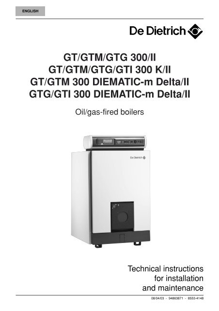
GT/GTM/GTG 300/II GT/GTM/GTG/GTI 300 K/II GT/GTM 300 ...
GT/GTM/GTG 300/II GT/GTM/GTG/GTI 300 K/II GT/GTM 300 ...
GT/GTM/GTG 300/II GT/GTM/GTG/GTI 300 K/II GT/GTM 300 ...

You also want an ePaper? Increase the reach of your titles
YUMPU automatically turns print PDFs into web optimized ePapers that Google loves.
ENGLISH<br />
<strong>GT</strong>/<strong>GT</strong>M/<strong>GT</strong>G <strong>300</strong>/<strong>II</strong><br />
<strong>GT</strong>/<strong>GT</strong>M/<strong>GT</strong>G/<strong>GT</strong>I <strong>300</strong> K/<strong>II</strong><br />
<strong>GT</strong>/<strong>GT</strong>M <strong>300</strong> DIEMATIC-m Delta/<strong>II</strong><br />
<strong>GT</strong>G/<strong>GT</strong>I <strong>300</strong> DIEMATIC-m Delta/<strong>II</strong><br />
Oil/gas-fired boilers<br />
Technical instructions<br />
for installation<br />
and maintenance<br />
08/04/03 - 94863871 - 8553-4148
● DECLARATION OF CONFORMITY /<br />
MARKING<br />
This product complies with the requirements of the<br />
ollowing European directives and standards :<br />
- 90.396 EEC, Gas Device Directive<br />
Relevant standards : EN 303.1 / EN 303.2 / EN 304.<br />
- 73/23 EEC, Low Voltage Directive<br />
Relevant standard : EN 60.335.1.<br />
- 89.336 EEC, Electromagnetic Compatibility Directive<br />
Relevant standards : EN 50.081.1 / EN 50.082.1 /<br />
EN 55.014<br />
- 92/42, Efficiency Directive<br />
It will be marketed in the following EEC member states :<br />
FR - DE - BE - LU - GB - IR - ES - PT - DK<br />
SE - AT - CH - GR - NL - IT<br />
with a gas burner of the associated category.<br />
CONTENTS<br />
1. GENERAL . . . . . . . . . . . . . . . . . . . . . . . . . . . . . . . . . . . . . . . . . . . . . . . . . . . . . . . . . . . . . . . . . . . . . . . . . . . . . . . 3<br />
1.1 Models available . . . . . . . . . . . . . . . . . . . . . . . . . . . . . . . . . . . . . . . . . . . . . . . . . . . . . . . . . . . . . . . . . . . . . . . 3<br />
1.2 Control panels available . . . . . . . . . . . . . . . . . . . . . . . . . . . . . . . . . . . . . . . . . . . . . . . . . . . . . . . . . . . . . . . . . 4<br />
1.3 Technical specifications - boilers for EXPORT . . . . . . . . . . . . . . . . . . . . . . . . . . . . . . . . . . . . . . . . . . . . . . . . 5<br />
1.4 Technical specifications - boilers for EUROPE . . . . . . . . . . . . . . . . . . . . . . . . . . . . . . . . . . . . . . . . . . . . . . . . 6<br />
1.5 Main dimensions . . . . . . . . . . . . . . . . . . . . . . . . . . . . . . . . . . . . . . . . . . . . . . . . . . . . . . . . . . . . . . . . . . . . . . . 7<br />
2. INSTALLING THE BOILER IN THE HEATING ROOM . . . . . . . . . . . . . . . . . . . . . . . . . . . . . . . . . . . . . . . . . . . . . 8<br />
3. ASSEMBLY . . . . . . . . . . . . . . . . . . . . . . . . . . . . . . . . . . . . . . . . . . . . . . . . . . . . . . . . . . . . . . . . . . . . . . . . . . . . . . 8<br />
4. HYDRAULIC CONNECTIONS . . . . . . . . . . . . . . . . . . . . . . . . . . . . . . . . . . . . . . . . . . . . . . . . . . . . . . . . . . . . . . . . 9<br />
4.1 Important recommendations for connecting the heating circuit to the boiler and to the drinking water system . . . . 9<br />
4.2 Filling the system . . . . . . . . . . . . . . . . . . . . . . . . . . . . . . . . . . . . . . . . . . . . . . . . . . . . . . . . . . . . . . . . . . . . . 10<br />
4.3 Sludge removale . . . . . . . . . . . . . . . . . . . . . . . . . . . . . . . . . . . . . . . . . . . . . . . . . . . . . . . . . . . . . . . . . . . . . . 10<br />
5. CHIMNEY CONNECTION . . . . . . . . . . . . . . . . . . . . . . . . . . . . . . . . . . . . . . . . . . . . . . . . . . . . . . . . . . . . . . . . . . 10<br />
5.1 General recommandation . . . . . . . . . . . . . . . . . . . . . . . . . . . . . . . . . . . . . . . . . . . . . . . . . . . . . . . . . . . . . . . 10<br />
5.2 Flue size . . . . . . . . . . . . . . . . . . . . . . . . . . . . . . . . . . . . . . . . . . . . . . . . . . . . . . . . . . . . . . . . . . . . . . . . . . . . 10<br />
5.3 Connection between boiler and flue pipe . . . . . . . . . . . . . . . . . . . . . . . . . . . . . . . . . . . . . . . . . . . . . . . . . . . 10<br />
6. FUEL-OIL OR GAS CONNECTIONS . . . . . . . . . . . . . . . . . . . . . . . . . . . . . . . . . . . . . . . . . . . . . . . . . . . . . . . . . 11<br />
7. ELECTRICAL CONNECTIONS . . . . . . . . . . . . . . . . . . . . . . . . . . . . . . . . . . . . . . . . . . . . . . . . . . . . . . . . . . . . . . 11<br />
8. MAINTENANCE . . . . . . . . . . . . . . . . . . . . . . . . . . . . . . . . . . . . . . . . . . . . . . . . . . . . . . . . . . . . . . . . . . . . . . . . . . 12<br />
8.1 Installation - water level . . . . . . . . . . . . . . . . . . . . . . . . . . . . . . . . . . . . . . . . . . . . . . . . . . . . . . . . . . . . . . . . . 12<br />
8.2 Boiler . . . . . . . . . . . . . . . . . . . . . . . . . . . . . . . . . . . . . . . . . . . . . . . . . . . . . . . . . . . . . . . . . . . . . . . . . . . . . . . 12<br />
8.3 Precautions required if the case of a boiler stop . . . . . . . . . . . . . . . . . . . . . . . . . . . . . . . . . . . . . . . . . . . . . . 14<br />
9. IDENTIFICATION PLATE . . . . . . . . . . . . . . . . . . . . . . . . . . . . . . . . . . . . . . . . . . . . . . . . . . . . . . . . . . . . . . . . . . 14<br />
10. WARRANTY . . . . . . . . . . . . . . . . . . . . . . . . . . . . . . . . . . . . . . . . . . . . . . . . . . . . . . . . . . . . . . . . . . . . . . . . . . . . . 15<br />
11. EXPLODED VIEWS AND LIST OF SPARE PARTS . . . . . . . . . . . . . . . . . . . . . . . . . . . . . . . . . . . . . . . . . . . . . . 15<br />
2<br />
● DIRECTIVE 97/23/EC<br />
Gas and oil boilers with a maximum operating temperature<br />
of 110°C and hot water tanks with a maximum operating<br />
pressure of 10 bar pertain to article 3.3 of the directive,<br />
and therefore, cannot be CE-marked to certify<br />
compliance with the directive 97/23 EC.<br />
The De Dietrich boilers and hot water tanks are designed<br />
and manufactured in accordance with the sound engineering<br />
practice, as requested in article 3.3 of the directive<br />
97/23/EC. This is certified by compliance with the directives<br />
90/396/EC, 92/42/EC, 73/23 EC and 89/336/EC.
1. GENERAL<br />
Warning :<br />
The boiler shall be assembled and<br />
installed by a qualified professional only.<br />
Strict compliance with these assembly,<br />
installation and maintenance instructions<br />
is a pre-requisite for the correct operation<br />
of the boiler.<br />
1.1 Models available<br />
<strong>GT</strong> <strong>300</strong>/<strong>II</strong> : automatic pressurised hot water boiler<br />
range designed for connection to a flue pipe. This<br />
boiler range can be equipped with a separate oil or gas<br />
fired burner.<br />
<strong>GT</strong>M <strong>300</strong>/<strong>II</strong> : automatic pressurised hot water boiler<br />
range designed for connection to a flue pipe. This<br />
boiler range is equipped with a one or two-stage oil burner,<br />
with an output power ranging from 55 to 280 kW.<br />
<strong>GT</strong>G <strong>300</strong>/<strong>II</strong> : automatic pressurised hot water boiler<br />
range designed for connecting to a flue pipe. This<br />
boiler range is equipped with a one or two-stage gas<br />
burner.<br />
<strong>GT</strong>I <strong>300</strong>/<strong>II</strong> : automatic pressurised hot water boiler<br />
range designed for connection to a flue pipe. This<br />
boiler range is equipped with a modulating gas pressure<br />
jet burner.<br />
3
1.2 Control panels available<br />
1.2.1 Standard control panel<br />
Control panel which integrates setting, control and safety<br />
devices, allowing the autonomous operation of the<br />
boiler without weather compensator. The standard control<br />
panel allows the connection of the boiler to the electrical<br />
cabinet of the heating room. The electrical cabinet<br />
can be equipped with control units.<br />
The standard control panel can be mounted on <strong>GT</strong> <strong>300</strong>/<strong>II</strong>,<br />
<strong>GT</strong>M <strong>300</strong>/<strong>II</strong> and <strong>GT</strong>G <strong>300</strong>/<strong>II</strong> boilers.<br />
1.2.2 K control panel<br />
Control panel which integrates setting, control and safety<br />
devices, allowing the autonomous operation of the<br />
boiler without weather compensator. The K control panel<br />
may be fitted with an optional SV-matic weather<br />
compensator for heating only or heating and domestic<br />
hot water production or an MB2 domestic hot water<br />
priority and regulation module.<br />
The boiler with K control panel may also be used as a<br />
“slave” boiler in cascaded installations with 2 to 10 boilers,<br />
one of which is fitted with a DIEMATIC-m Delta<br />
control panel.<br />
The K control panel can be mounted on <strong>GT</strong> <strong>300</strong>/<strong>II</strong>,<br />
<strong>GT</strong>M <strong>300</strong>/<strong>II</strong>, <strong>GT</strong>G <strong>300</strong>/<strong>II</strong> and <strong>GT</strong>I <strong>300</strong>/<strong>II</strong> boilers which<br />
then become <strong>GT</strong> <strong>300</strong> K/<strong>II</strong>, <strong>GT</strong>M <strong>300</strong> K/<strong>II</strong>, <strong>GT</strong>G <strong>300</strong> K/<strong>II</strong><br />
and <strong>GT</strong>I <strong>300</strong> K/<strong>II</strong> boilers.<br />
1.2.3 Diematic-m Delta control panel<br />
Electronic high level control panel with digital display,<br />
which integrates setting, control and safety devices allowing<br />
the autonomous operation of the boiler.<br />
The DIEMATIC-m Delta control panel integrates from<br />
factory a weather compensator, which allows regulation<br />
according to the external temperature.<br />
<strong>GT</strong> <strong>300</strong> DIEMATIC-m Delta boilers are also used as<br />
“master” boilers in cascaded installations with 2 to 10<br />
boilers. The other boilers (1-9) must necessarily be fitted<br />
with a K control panel equipped with a cascade pcb.<br />
The DIEMATIC-m Delta control panel can be mounted<br />
on <strong>GT</strong> <strong>300</strong>/<strong>II</strong>, <strong>GT</strong>M <strong>300</strong>/<strong>II</strong>, <strong>GT</strong>G <strong>300</strong>/<strong>II</strong> and <strong>GT</strong>I <strong>300</strong>/<strong>II</strong><br />
boilers which then become <strong>GT</strong> <strong>300</strong> DIEMATIC-m<br />
Delta/<strong>II</strong>, <strong>GT</strong>M <strong>300</strong> DIEMATIC-m Delta/<strong>II</strong>, <strong>GT</strong>G <strong>300</strong><br />
DIEMATIC-m Delta/<strong>II</strong> and <strong>GT</strong>I <strong>300</strong> DIEMATIC-m<br />
Delta/<strong>II</strong> boilers.<br />
4<br />
D I E M T I C<br />
30<br />
I<br />
0<br />
30<br />
I<br />
0<br />
8219N036<br />
8555N040<br />
8555N041
1.3 Technical specifications - boilers for EXPORT<br />
Working conditions :<br />
- Maximum operating temperature : 100°C<br />
- Maximum operating pressure : 6 bar<br />
- Thermostat adjustment range : 30 - 90°C<br />
- Safety thermostat setting : 110°C<br />
Boiler type<br />
<strong>GT</strong> 304/<strong>II</strong> <strong>GT</strong> 305/<strong>II</strong> <strong>GT</strong> 306/<strong>II</strong> <strong>GT</strong> 307/<strong>II</strong> <strong>GT</strong> 308/<strong>II</strong> <strong>GT</strong> 309/<strong>II</strong><br />
<strong>GT</strong>M 304/<strong>II</strong> <strong>GT</strong>M 305/<strong>II</strong> <strong>GT</strong>M 306/<strong>II</strong> <strong>GT</strong>M 307/<strong>II</strong> <strong>GT</strong>M 308/<strong>II</strong> <strong>GT</strong>M 309/<strong>II</strong><br />
<strong>GT</strong>G 304/<strong>II</strong> <strong>GT</strong>G 305/<strong>II</strong> <strong>GT</strong>G 306/<strong>II</strong> <strong>GT</strong>G 307/<strong>II</strong> <strong>GT</strong>G 308/<strong>II</strong> <strong>GT</strong>G 309/<strong>II</strong><br />
<strong>GT</strong>I 304/<strong>II</strong> <strong>GT</strong>I 305/<strong>II</strong> <strong>GT</strong>I 306/<strong>II</strong> <strong>GT</strong>I 307/<strong>II</strong> <strong>GT</strong>I 308/<strong>II</strong> <strong>GT</strong>I 309/<strong>II</strong><br />
Range of output power kW 70-105 105-140 140-180 180-230 230-280 280-330<br />
Number of sections 4 5 6 7 8 9<br />
Burner (optional) Oil (<strong>GT</strong>M) M 31/32-5S M 32-6S M 32-7S M 32-8S M 32-9S M 42-1S<br />
Natural gas (<strong>GT</strong>G) G 31/32-5S G 32-6S G 32-7S G 32-8S G 32-9S G 43-1S<br />
Gas modulating (<strong>GT</strong>I) G 33-5N G 33-6N G 33-7N G 33-8N G 33-9N G 43-1S<br />
Number of baffle plates 6 10 10 6 6 6<br />
Water capacity l 96 116 136 156 176 196<br />
Stand-by losses at 50 °C (D) % 0.17 0.14 0.13 0.11 0.10 0.09<br />
Water resistance (E) ∆t=15 K mbar (B) 6.2 10.9 20.4 30 44.5 63.8<br />
Combustion chamber<br />
- diameter mm 377 377 377 377 377 377<br />
- lenght mm 621 781 941 1101 1261 1396<br />
- volume m3 0.096 0.122 0.148 0.174 0.200 0.226<br />
Volume of the flue gas circuit m 3 0.163 0.206 0.249 0.292 0.335 0;378<br />
(combustion chamber + flue ways)<br />
Flue gas temperature (E) °C 210 210 210 210 210 210<br />
Mass flue gas flow rate Fuel oil kg/h 172 231 297 379 464 541<br />
Natural gas kg/h 160 206 270 331 411 500<br />
Pressure in the combustion chamber(C)(E) mbar(B) +0.3 +0.6 +1.1 +1.6 +2.2 +2.5<br />
Net weight <strong>GT</strong> kg 510 608 694 791 886 977<br />
<strong>GT</strong>M/<strong>GT</strong>G/<strong>GT</strong>I kg 529 627 714 811 921 1012<br />
- (A) Stand-by losses as per applicable standard.<br />
- (B) 1 mbar = 10 mmWC = 10 daPa<br />
- (C) Pressure in the combustion chamber for 0<br />
nozzle pressure.<br />
- (D) Nominal operation (top power of the power range)<br />
5<br />
Test conditions : CO2 with oil = 13 %<br />
CO2 with natural gas = 9.5 %<br />
Ta (room temperature) = 20°C
1.4 Technical specifications - boilers for EUROPE<br />
Working conditions :<br />
- Maximum operating temperature : 100°C<br />
- Maximum operating pressure : 6 bar<br />
- Thermostat adjustment range : 30 - 90°C<br />
- Safety thermostat setting : 110°C<br />
Boiler type<br />
<strong>GT</strong> 304/<strong>II</strong> <strong>GT</strong> 305/<strong>II</strong> <strong>GT</strong> 306/<strong>II</strong> <strong>GT</strong> 307/<strong>II</strong> <strong>GT</strong> 308/<strong>II</strong> <strong>GT</strong> 309/<strong>II</strong><br />
<strong>GT</strong>M 304/<strong>II</strong> <strong>GT</strong>M 305/<strong>II</strong> <strong>GT</strong>M 306/<strong>II</strong> <strong>GT</strong>M 307/<strong>II</strong> <strong>GT</strong>M 308/<strong>II</strong> <strong>GT</strong>M 309/<strong>II</strong><br />
<strong>GT</strong>G 304/<strong>II</strong> <strong>GT</strong>G 305/<strong>II</strong> <strong>GT</strong>G 306/<strong>II</strong> <strong>GT</strong>G 307/<strong>II</strong> <strong>GT</strong>G 308/<strong>II</strong> <strong>GT</strong>G 309/<strong>II</strong><br />
<strong>GT</strong>I 304/<strong>II</strong> <strong>GT</strong>I 305/<strong>II</strong> <strong>GT</strong>I 306/<strong>II</strong> <strong>GT</strong>I 307/<strong>II</strong> <strong>GT</strong>I 308/<strong>II</strong> <strong>GT</strong>I 309/<strong>II</strong><br />
Range of output power kW 55-90 90-115 115-150 150-185 185-230 230-280<br />
Range of used input power kW 61-100 100-128 128-167 167-206 206-256 256-311<br />
Burner Oil (<strong>GT</strong>M) M 31-4S M 31-5S M 32-6S M 32-7S M 32-8S M 32-9S<br />
Natural gas (<strong>GT</strong>G) G 31-4S G 32-5S G 32-6S G 32-7S G 32-8S G 32-9S<br />
gas modulating (<strong>GT</strong>I) G 33-4N G 33-5N G 33-6N G 33-7N G 33-8N G 33-9N<br />
Number of sections 4 5 6 7 8 9<br />
Number of baffle plates 6 10 10 10 12 12<br />
Water capacity l 96 116 136 156 176 196<br />
Stand-by losses at 50 °C (A) % 0.150 0.135 0.125 0.115 0.100 0.085<br />
Water resistance ∆t=10 K mbar (B) (C) 11 18 31 46 68 105<br />
Combustion chamber<br />
∆t=15 K mbar (B) (C) 4.6 7.4 14.2 19.5 30;1 46<br />
∆t=20 K mbar (B) (C) 2.6 4.2 8 11 17 26<br />
- diameter mm 377 377 377 377 377 377<br />
- length mm 621 781 941 1101 1261 1396<br />
- volume m3 0.096 0.122 0.148 0.174 0.200 0.226<br />
Volume of flue gas circuit m 3 0.163 0.206 0.249 0.292 0.335 0.378<br />
(Combustion chamber + flue ways)<br />
Flue gas temperature (B) °C 200 190 190 190 190 190<br />
Mass flue gas flow rate (B) Fuel oil kg/h 149 191 248 306 381 463<br />
Natural gas kg/h 160 206 270 331 411 500<br />
Pressure in the Combustion chamber(B)(D) mbar (C) 0.2 0.4 0.7 1.2 1.8 2.2<br />
Net weight <strong>GT</strong> kg 510 608 694 791 886 977<br />
<strong>GT</strong>M/<strong>GT</strong>G/<strong>GT</strong>I kg 529 627 714 811 921 1012<br />
- (A) Stand-by losses (as per NFD 30 002) in % of the<br />
input power.<br />
- (B) Nominal operation (top power of the power range)<br />
- (C) 1 mbar = 10 mmWC = 10 daPa<br />
- (D) Pressure in the Combustion chamber for 0 nozzle<br />
pressure.<br />
The pressure at the nozzle must never exceed<br />
0,2 mbar.<br />
6<br />
Test conditions : CO2 with oil = 13 %<br />
CO2 with natural gas = 9.5 %<br />
Ta (room temperature) = 20°C
1.5 Main dimensions<br />
● <strong>GT</strong> <strong>300</strong>/<strong>II</strong><br />
H<br />
1192<br />
398<br />
796<br />
L<br />
D<br />
(a)<br />
153<br />
A<br />
53<br />
398<br />
101 594 101<br />
Rp 2 1/2 diameter sludge<br />
removal hole<br />
137<br />
387<br />
Ø R<br />
98<br />
P 195 105<br />
Boiler type <strong>GT</strong>... 304/<strong>II</strong> 305/<strong>II</strong> 306/<strong>II</strong> 307/<strong>II</strong> 308/<strong>II</strong> 309/<strong>II</strong><br />
Standard A 130 130 130 130 130 130<br />
control B 105 105 105 105 105 105<br />
panel C 165 165 165 165 165 165<br />
D 738 738 738 738 738 738<br />
H 1297 1297 1297 1297 1297 1297<br />
K + DIEMATIC-m A 355 355 355 355 355 355<br />
Delta B 195 195 195 195 195 195<br />
control C 145 145 145 145 145 145<br />
panel D 755 755 755 755 755 755<br />
H 1387 1387 1387 1387 1387 1387<br />
E <strong>GT</strong>M version 347 387 387 387 387 417<br />
<strong>GT</strong>G/<strong>GT</strong>I version 459 459 459 549 549 549<br />
L 991 1151 1311 1471 1631 1791<br />
M <strong>GT</strong>M version 1338 1538 1698 1858 2018 2208<br />
<strong>GT</strong>G/<strong>GT</strong>I version 1450 1610 1770 1930 2180 2340<br />
P 490 650 810 970 1130 1290<br />
ø R 180 180 180 200 200 200<br />
7<br />
153<br />
● <strong>GT</strong>M <strong>300</strong>/<strong>II</strong> - <strong>GT</strong>G <strong>300</strong>/<strong>II</strong> - <strong>GT</strong>I <strong>300</strong>/<strong>II</strong><br />
H<br />
1192<br />
796<br />
L<br />
D<br />
153<br />
A<br />
(a) 53<br />
398 398<br />
101 594 101<br />
Rp 2 1/2 diameter sludge<br />
removal hole<br />
137<br />
387<br />
Ø R<br />
98<br />
153<br />
M<br />
C<br />
B<br />
ø 2” 1/2 heating return<br />
(flange + counter flange)<br />
C<br />
B<br />
P 195 E<br />
105<br />
ø 2” 1/2 heating return<br />
(flange + counter flange)<br />
ø 2” 1/2 heating flow<br />
(flange + counter flange)<br />
= =<br />
115<br />
137<br />
827<br />
1017<br />
8553N001<br />
Rp 1 1/2 draining outlet<br />
(supplied with plug)<br />
ø 2” 1/2 heating flow<br />
(flange + counter flange)<br />
= =<br />
115<br />
137<br />
827<br />
1017<br />
8553N002<br />
Rp 1 1/2 draining outlet<br />
(supplied with plug)<br />
(a) Rp 1 1/2 socket<br />
for safety unit<br />
Rp = tapped
2. INSTALLING THE BOILER IN THE HEATING ROOM<br />
Comply with the minimum dimensions indicated in the<br />
drawing below in order to ensure that the boiler is accessible<br />
from all sides.<br />
Ventilation : in order to enable the intake of combustion<br />
air, appropriate ventilation having the section and<br />
location required by applicable standards shall be provided<br />
in the boiler room.<br />
Air outlet<br />
8553N003B<br />
Boiler type<br />
Mind the volume of the burner when the door is open.<br />
These dimensions must be adapted for systems with<br />
several cascaded boilers.<br />
3. ASSEMBLY<br />
1m<br />
B<br />
1,19m<br />
0,15m<br />
A<br />
1,5m<br />
<strong>GT</strong> <strong>GT</strong> <strong>GT</strong> <strong>GT</strong> <strong>GT</strong> <strong>GT</strong><br />
304/<strong>II</strong> 305/<strong>II</strong> 306/<strong>II</strong> 307/<strong>II</strong> 308/<strong>II</strong> 309/<strong>II</strong><br />
Dimension A mm 840 1000 1160 1320 1480 1640<br />
B<br />
Standard control panel mm 105 105 105 105 105 105<br />
K, Diematic -m Delta cont. pan. mm 195 195 195 195 195 195<br />
See the yellow booklet for the assembly instructions.<br />
8<br />
Please note that boilers installed in or<br />
close to rooms in which the atmosphere<br />
is polluted with chlorine or fluorine compounds<br />
may be subject to high corrosion.<br />
For example : hairdressing salons, industrial<br />
premises (solvents), cooling equipment<br />
etc.<br />
Boilers installed in such locations shall<br />
not be covered by the warranty.<br />
0,5m 0,8m 0,5m<br />
Air inlet
4. HYDRAULIC CONNECTIONS<br />
4.1 Important recommendations for connecting the heating circuit to the boiler and<br />
to the drinking water system<br />
The installation shall be made in accordance with<br />
applicable regulations and codes of practice.<br />
The expansion tank shall be connected to the boiler<br />
without any valve or stop valve between the boiler and<br />
the expansion tank.<br />
Similarly, the safety valve shall be connected<br />
to the boiler without any valve or stop valve<br />
between the boiler and the safety valve.<br />
Example of installation :<br />
The example below does not cover all the possible cases of<br />
use. It is only aimed at drawing attention to the basic rules<br />
which must be complied with. In all events, comply with applicable<br />
codes of practice and national or local regulations.<br />
Example of a <strong>GT</strong> <strong>300</strong>/<strong>II</strong> boiler with domestic hot water<br />
production via one or more independent calorifiers.<br />
11<br />
27<br />
3<br />
10<br />
4 5<br />
7 26 25 7<br />
8<br />
7<br />
7<br />
7<br />
13<br />
1. Heating outlet<br />
2. Heating return<br />
3. 3 bar safety valve and pressure gauge<br />
4. Flow switch (if necessary)<br />
5. Air separator<br />
6. Automatic venting valve<br />
7. Valve<br />
8. Recycling pump (recommended for <strong>GT</strong> 304/<strong>II</strong>,<br />
compulsory for <strong>GT</strong> 305/<strong>II</strong> to 309/<strong>II</strong>)<br />
9. Expansion tank<br />
10. Draining valve<br />
11. Sludge removal valve<br />
12. Mixing valve<br />
13. Non return valve<br />
14. Heating pump<br />
15. Low-water safety pressure-sensitive switch<br />
9<br />
7<br />
6<br />
7<br />
22<br />
10<br />
7<br />
6 7<br />
9<br />
21<br />
The heating system shall be designed and installed in<br />
a way as to prevent the water from the heating circuit<br />
and any substances added to it from flowing back into<br />
the drinking water circuit located before it. The installation<br />
shall not be directly connected to the drinking<br />
water system.<br />
12 7<br />
1<br />
17<br />
7<br />
24<br />
13<br />
23<br />
13<br />
7<br />
19<br />
7<br />
14<br />
20<br />
15<br />
10<br />
16<br />
7<br />
2<br />
Heating<br />
circuit<br />
8219N008A<br />
18<br />
16. Sludge decanting pot (particularly recommended for<br />
older heating systems)<br />
17. Independent calorifier<br />
18. Sealed safety unit calibrated to 7 bar with indicator<br />
type discharger<br />
19. Pressure reducer (if mains pressure > 5.5 bar)<br />
20. Domestic cold water inlet<br />
21. Domestic hot water outlet<br />
22. Load pump<br />
23. Domestic hot water circulation pump (optional)<br />
24. DHW circulation loop return<br />
25. Water meter (if any)<br />
26. Water treatment if TH > 25°<br />
27. Heating circuit filling (with disconnector if required<br />
under applicable regulations).
4.2 Filling the system<br />
Filling shall be performed with a low flow rate from a low<br />
point in the boiler room in order to ensure that all the air<br />
in the boiler is vented from the high point of the system.<br />
VERY IMPORTANT : Instructions for starting<br />
up the boiler for the first time after<br />
the system is fully or partly drained :<br />
If all the air is not vented naturally to an<br />
expansion tank which opens out onto the<br />
air, the system must include manual venting<br />
valves, in addition to automatic venting<br />
valves with the capability to vent the system<br />
by themselves when it is<br />
operating. The manual venting valves are<br />
used to vent all the high points of the system<br />
and to make sure that the filled system<br />
is free of air before the burner is turned on.<br />
4.3 Sludge removal<br />
A tapped 2” 1/2 hole with a plug has been provided on<br />
the bottom of the front of the boiler to remove the sludge.<br />
Fit a quarter-turn valve on the opening to remove<br />
the sludge (the fitter can also use the optional desludging<br />
kit - package FD 37). Sludge removal leads to the<br />
draining of large quantities of water. After this operation,<br />
fill the installation according to § 4.2.<br />
5. CHIMNEY CONNECTION<br />
5.1 General recommandation<br />
The high-performance features of modern boilers and<br />
their use in specific conditions as a result of the advance<br />
in burner technology (e.g. modulated low-temperature<br />
operation) lead to very low flue gas temperatures.<br />
This requires :<br />
- the use of flue pipes designed to enable the flow of<br />
condensates which may result from such operating<br />
modes, in order to prevent damage to the chimney;<br />
5.2 Flue size<br />
Refer to applicable regulations while determining the<br />
size of the flue. Please note that <strong>GT</strong> <strong>300</strong>/<strong>II</strong> boilers have<br />
pressurised furnaces and that the pressure at the nozzle<br />
must not exceed 0 mbar, unless special precautions<br />
have been taken to seal the connection between the<br />
nozzle and the chimney outlet.<br />
5.3 Connection between boiler and flue pipe<br />
The boiler shall be connected to the flue pipe in accordance<br />
with codes of practice with a sealed pipe made<br />
of material capable of withstanding hot combustion gas<br />
and any acid condensation. The connection shall be<br />
removable and offer minimum load losses, i.e. it must<br />
be as short as possible with no sudden change in section.<br />
Its diameter shall always be at least equal to that of<br />
10<br />
Always stop the recycling pumps before filling.<br />
Do not add cold water suddenly into the<br />
boiler when it is hot.<br />
Note : never replace a boiler in an existing system<br />
without carefully rinsing the system first. Install a sludge<br />
decanting pot on the return pipe, very close to the<br />
boiler.<br />
- the installation of a draining tee at the foot of the<br />
chimney.<br />
The use of a draught moderator is recommended as<br />
well.<br />
If required, the baffle plates of the four upper flue ways<br />
may be removed partly to increase the flue gas temperature.<br />
the boiler outlet, i.e. ø 180 mm for boilers with 4, 5 and<br />
6 sections and ø 200 mm for those with 7, 8 and 9<br />
sections.<br />
To allow the setting of the burner and control of the<br />
combustion, the installer must preview a measurement<br />
hole (10 mm ø) on the flue pipe.
6. FUEL-OIL OR GAS CONNECTIONS<br />
Refer to the instructions supplied with the burner.<br />
Burner<br />
door<br />
insulation<br />
Deflector<br />
8553N004<br />
Important :<br />
The burner head deflector must be in line<br />
with the insulation of the burner door.<br />
125<br />
7. ELECTRICAL CONNECTIONS<br />
Please refer to the instructions supplied with the control panel.<br />
11<br />
45°<br />
45°<br />
Burner door drilling diameters<br />
ø 155 (1)<br />
ø 175 (1)<br />
ø 135<br />
Door thickness with 125 mm insulation<br />
(1) precuttings<br />
4 ø M8 on<br />
ø 170<br />
4 markings<br />
on ø 200<br />
4 markings<br />
on ø 220<br />
8219N112
8. MAINTENANCE<br />
8.1 Installation - water level<br />
Regularly check the level of the water in the system and<br />
top up if required, taking care not to add suddenly cold<br />
water into the boiler, when it is hot. This operation should<br />
be required only a few times in each heating season,<br />
with very small quantities of water.<br />
8.2 Boiler<br />
The boiler will only operate efficiently if is kept clean.<br />
The boiler should be cleaned as soon as required and<br />
as the chimney, at least once a year, or more, depending<br />
upon applicable regulations.<br />
● Cleaning the flue gas circuit<br />
- Turn off the power to the boiler.<br />
- Remove the front panel.<br />
- Open the sweeping door (upper door) by unfastening<br />
the four closing nuts (17 mm spanner).<br />
- Remove the baffle plates.<br />
- Carefully sweep the six flue ways with the brush<br />
supplied.<br />
- Also brush the baffle plates and the front panel.<br />
- Use a vacuum cleaner if possible.<br />
- Put the baffle plates back in place complying with the<br />
instructions given on next page.<br />
Important : the first two baffle plates of the two lower<br />
flue ways are fitted with stops to position them properly<br />
in the flue ways.<br />
- Close the door.<br />
Cleaning the combustion chamber<br />
- open the burner door (lower door) by<br />
unfastening the four closing nuts (17<br />
mm spanner),<br />
- brush the inside of the combustion<br />
chamber,<br />
- vacuum any soot deposited in the combustion<br />
chamber,<br />
- close the door and put back the front<br />
panel.<br />
12<br />
Otherwise, look for the leak and repair it immediately.<br />
We advise you against draining the heating system<br />
unless it is absolutely necessary.<br />
8553N005<br />
The operations described below shall only<br />
be performed with the boiler and main<br />
supply off.<br />
8553N049
● Positionning of the baffle plates<br />
A<br />
B<br />
C<br />
Stops<br />
8553N006<br />
- All boilers excepted Export-boilers<br />
Baffle plates Flue ways <strong>GT</strong> 304/<strong>II</strong> <strong>GT</strong> 305/<strong>II</strong> <strong>GT</strong> 306/<strong>II</strong> <strong>GT</strong> 307/<strong>II</strong> <strong>GT</strong> 308/<strong>II</strong> <strong>GT</strong> 309/<strong>II</strong><br />
- upper - lg 410 mm A + B 8 8 4<br />
- lg 570 mm A+B 4 4 8 8<br />
- lower - lg 412 mm C 2 2 2 2 4 2<br />
- lg 572 mm C 2<br />
- ”Export” boilers<br />
Baffle plates Flue ways <strong>GT</strong> 304/<strong>II</strong> <strong>GT</strong> 305/<strong>II</strong> <strong>GT</strong> 306/<strong>II</strong> <strong>GT</strong> 307/<strong>II</strong> <strong>GT</strong> 308/<strong>II</strong> <strong>GT</strong> 309/<strong>II</strong><br />
- upper - lg 410 mm A + B 8 8 0 0 0<br />
- lg 570 mm A+B 4 4 4 4<br />
- lower - lg 412 mm C 2 2 2 2 2 2<br />
13<br />
Important :<br />
The first two baffle plates of the two lower<br />
flue ways are fitted with stops to position<br />
them properly in the flue ways.
● Cleaning the flue gas box<br />
Proceed as follows :<br />
- open the left and right-hand sweeping covers of the<br />
flue gas box (2 H12 nuts and flat washers) with a<br />
19 mm spanner and vacuum any soot deposited<br />
there.<br />
- put back the sweeping covers.<br />
● Cleaning the burner<br />
Refer to the instructions supplied with the burner.<br />
8.3 Precautions required in the case of a boiler stop<br />
- The boiler and the chimney must be swept carefully.<br />
- Close all the doors of the boiler to prevent air from circulating<br />
inside the boiler.<br />
- If the boiler is to be stopped for several months, we<br />
advise removing the pipe which connects the boiler to<br />
the chimney and closing off the nozzle with a cover.<br />
9. IDENTIFICATION PLATE<br />
(1) 02=2002,<br />
03=2003,<br />
...<br />
Type of boiler<br />
14<br />
8553N007<br />
- We recommend the use of a correctly dosed antifreeze<br />
agent to keep the heating circuit from freezing.<br />
If this cannot be done, drain the system completely.<br />
F 67110 NIEDERBRONN<br />
Unit serial no.<br />
XX - XX<br />
Date of manufacture<br />
8553N047<br />
year (1)<br />
week<br />
F 67110 NIEDERBRONN
10. WARRANTY<br />
You have just purchased a DE DIETRICH appliance and<br />
we thank you for the trust you have placed in our products.<br />
Please note that your appliance will provide good<br />
service for a longer period of time if it is regularly checked<br />
and maintained.<br />
Your fitter and the DE DIETRICH customer support network<br />
are at your disposal at all times.<br />
Warranty terms<br />
Starting from the purchase date shown on the original<br />
fitter’s invoice, your appliance has a contractual<br />
guarantee against any manufacturing defect.<br />
The length of the guarantee is mentioned in the price<br />
catalogue.<br />
The manufacturer is not liable for any improper use of<br />
the appliance or failure to maintain or install the unit<br />
correctly (the user shall take care to ensure that the<br />
system is installed by a qualified fitter).<br />
In particular, the manufacturer shall not be held responsible<br />
for any damage, loss or injury caused by installations<br />
which do not comply with the following:<br />
- applicable local laws and regulations;<br />
- specific requirements relating to the installation,<br />
such as national and/or local regulations;<br />
- the manufacturer’s instructions, in particular<br />
those relating to the regular maintenance of the<br />
unit;<br />
- the rules of the profession.<br />
11. EXPLODED VIEWS AND LIST OF SPARE PARTS<br />
Refer to the following pages.<br />
15<br />
The warranty is limited to the exchange or repair of<br />
such parts as have been recognised to be faulty by<br />
our technical department and does not cover labour,<br />
travel and carriage costs.<br />
The warranty shall not apply to the replacement or<br />
repair of parts damaged by normal wear and tear,<br />
negligence, repairs by unqualified parties, faulty or<br />
insufficient monitoring and maintenance, faulty power<br />
supply or the use of unsuitable fuel.<br />
Sub-assemblies such as motors, pumps, electric<br />
valves etc. are guaranteed only if they have never been<br />
dismantled.<br />
The above provisions do not restrict the benefit of the<br />
legal laws regarding hidden defects applicable in the<br />
buyer’s country.<br />
TR112
20<br />
16<br />
10.2<br />
10.1<br />
10<br />
8553N059<br />
Spare parts<br />
Note : while ordering spare parts, do not forget to provide the code number given in the list opposite the part reference.<br />
BOILER BODY AND ACCESSORIES<br />
19 16 18<br />
51<br />
11<br />
50<br />
11<br />
9<br />
31 32<br />
Bag of fasteners<br />
for boiler body<br />
1<br />
Bag of fasteners<br />
for buner door<br />
28<br />
16<br />
2<br />
4<br />
16<br />
3<br />
5<br />
33<br />
6<br />
8<br />
7<br />
12<br />
29<br />
12<br />
30<br />
13<br />
21<br />
25<br />
26<br />
34<br />
16<br />
16<br />
15<br />
14<br />
24<br />
23<br />
8553-4156<br />
<strong>GT</strong>/<strong>GT</strong>M/<strong>GT</strong>G <strong>300</strong>/<strong>II</strong><br />
<strong>GT</strong>/<strong>GT</strong>M/<strong>GT</strong>G/<strong>GT</strong>I <strong>300</strong> K/<strong>II</strong><br />
<strong>GT</strong>/<strong>GT</strong>M/<strong>GT</strong>G/<strong>GT</strong>I <strong>300</strong> DIEMATIC-m Delta/<strong>II</strong><br />
DE DIETRICH THERMIQUE S.A.S. au capital de 21 686 370 • Centre Pièces de Rechange/Spare Part Centre<br />
4, rue d'Oberbronn • F-67110 REICHSHOFFEN • Tél. : +33 3 88 80 26 50 • Fax : +33 3 88 80 26 98<br />
cpr@ddt.dedietrich.com<br />
22 27<br />
17<br />
17<br />
AD042A
INSULATION<br />
BASE FRAME<br />
8553N060<br />
90<br />
70<br />
12x<br />
<strong>GT</strong>/<strong>GT</strong>M/<strong>GT</strong>G <strong>300</strong>/<strong>II</strong><br />
<strong>GT</strong>/<strong>GT</strong>M/<strong>GT</strong>G/<strong>GT</strong>I <strong>300</strong> K/<strong>II</strong><br />
<strong>GT</strong>/<strong>GT</strong>M/<strong>GT</strong>G/<strong>GT</strong>I <strong>300</strong> DIEMATIC-m Delta/<strong>II</strong><br />
2/6<br />
8553N061
CASING<br />
100<br />
104<br />
102<br />
Bag of casing<br />
fasteners<br />
109<br />
106<br />
<strong>GT</strong>/<strong>GT</strong>M/<strong>GT</strong>G <strong>300</strong>/<strong>II</strong><br />
<strong>GT</strong>/<strong>GT</strong>M/<strong>GT</strong>G/<strong>GT</strong>I <strong>300</strong> K/<strong>II</strong><br />
<strong>GT</strong>/<strong>GT</strong>M/<strong>GT</strong>G/<strong>GT</strong>I <strong>300</strong> DIEMATIC-m Delta/<strong>II</strong><br />
107<br />
3/6<br />
102<br />
101<br />
103<br />
108<br />
105<br />
8553N062
STANDARD CONTROL PANEL (Package FA3)<br />
K CONTROL PANEL (Package FA2)<br />
30<br />
I<br />
0<br />
DIEMATIC-m Delta CONTROL PANEL (Package FA1)<br />
D I E M T I C<br />
30<br />
I<br />
0<br />
<strong>GT</strong>/<strong>GT</strong>M/<strong>GT</strong>G <strong>300</strong>/<strong>II</strong><br />
<strong>GT</strong>/<strong>GT</strong>M/<strong>GT</strong>G/<strong>GT</strong>I <strong>300</strong> K/<strong>II</strong><br />
<strong>GT</strong>/<strong>GT</strong>M/<strong>GT</strong>G/<strong>GT</strong>I <strong>300</strong> DIEMATIC-m Delta/<strong>II</strong><br />
4/6<br />
See separate list of the standard control panel<br />
See separate list of the K control panel<br />
8219N036<br />
8555N040<br />
See separate list of the Diematic-m Delta control panel<br />
8555N041
<strong>GT</strong>/<strong>GT</strong>M/<strong>GT</strong>G <strong>300</strong>/<strong>II</strong> - <strong>GT</strong>/<strong>GT</strong>M/<strong>GT</strong>G/<strong>GT</strong>I <strong>300</strong> K/<strong>II</strong><br />
<strong>GT</strong>/<strong>GT</strong>M/<strong>GT</strong>G/<strong>GT</strong>I <strong>300</strong> DIEMATIC-m Delta/<strong>II</strong><br />
Ref. Code no. DESCRIPTION Ref. Code no. DESCRIPTION<br />
BOILER BODY<br />
1 8219-8912 Complete rear section<br />
2 8219-8966 Complete intermediate section<br />
3 8219-8976 Complete front section<br />
4 8116-0571 Nipple<br />
5 8219-8968 Complete assembly rod, 4 sections<br />
5 8219-8969 Complete assembly rod, 5 sections<br />
5 8219-8970 Complete assembly rod, 6 sections<br />
5 8219-8971 Complete assembly rod, 7 sections<br />
5 8219-8972 Complete assembly rod, 8 sections<br />
5 8219-8973 Complete assembly rod, 9 sections<br />
6 8202-0028 Rp 2 1/2 plug with Rp 1/2 hole<br />
7 9536-5611 Rp 1/2 pocket<br />
8 9495-0249 R 1 1/2 plug<br />
9 8553-5513 Flow flange, 3 to 9 sections<br />
10 8553-5514 Return flange, 3 to 7 sections<br />
10.1 8553-5515 Return flange with water distributing tube, 8 sections<br />
10.2 8553-5516 Return flange with water distributing tube, 9 sections<br />
11 9501-3022 Flange gasket<br />
12 8104-8984 Hinge<br />
13 8219-8916 Complete sweeping door<br />
14 9425-0306 Inner protection of sweeping door<br />
15 9425-0305 External insulation of sweeping door<br />
16 9508-6032 ø 10 Thermocord gasket<br />
17 9756-0203 Pin for hinge ø12 x 350<br />
18 8219-8913 Complete 180 ø nozzle for 4 - 6 sections<br />
18 8219-8914 Complete 200 ø nozzle for 7 - 9 sections<br />
19 8219-0206 Right-hand nozzle cover<br />
20 8219-0207 Left-hand nozzle cover<br />
21 8219-8953 Complete 135 ø burner door<br />
22 9425-0303 Internal burner door protection (soft)<br />
23 9425-0302 Intermediate burner door protection (soft)<br />
24 9425-0301 External burner door protection (rigid)<br />
25 8015-7700 Sight glass + gaskets<br />
26 9757-0027 Sight glass flange<br />
27 9495-0050 1/4" plug<br />
28 8219-0539 Guide rail for burner door<br />
29 8219-0017 410 mm long upper baffle plate<br />
29 8219-0018 570 mm long upper baffle plate<br />
30 8219-0019 412 mm long lower baffle plate<br />
30 8219-0020 572 mm long lower baffle plate<br />
31 8219-7724 Bag of fasteners for boiler body<br />
32 8219-8957 Bag of fasteners for burner door<br />
33 9430-5027 Lubricant for nipple<br />
5/6<br />
34 9432-0214 Silicone filler (Novasil S 17)<br />
50 9750-5025 Brush<br />
MISCELLANEOUS<br />
51 9750-5076 1000 mm long brush rod<br />
51 9750-5060 1<strong>300</strong> mm long brush rod<br />
BASE FRAME<br />
70 8553-7060 Complete base frame, 4 sections - package FD 30<br />
70 8553-7061 Complete base frame, 5 sections - package FD 31<br />
70 8553-7062 Complete base frame, 6 sections - package FD 32<br />
70 8553-7063 Complete base frame, 7 sections - package FD 33<br />
70 8553-7064 Complete base frame, 8 sections - package FD 34<br />
70 8553-7065 Complete base frame, 9 sections - package FD 35<br />
INSULATION<br />
90 8553-5507 Complete boiler body insulation, 4 sections<br />
90 8553-5508 Complete boiler body insulation, 5 sections<br />
90 8553-5509 Complete boiler body insulation, 6 sections<br />
90 8553-5510 Complete boiler body insulation, 7 sections<br />
90 8553-5511 Complete boiler body insulation, 8 sections<br />
90 8553-5512 Complete boiler body insulation, 9 sections<br />
CASING<br />
100 8553-5500 Complete casing, 4 sections<br />
100 8553-5501 Complete casing, 5 sections<br />
100 8553-5502 Complete casing, 6 sections<br />
100 8553-5503 Complete casing, 7 sections<br />
100 8553-5504 Complete casing, 8 sections<br />
100 8553-5505 Complete casing, 9 sections<br />
101 8219-1000 Insulated front panel<br />
102 8553-8000 Upper fastening bracket<br />
103 8553-5506 Insulated lower cover<br />
104 8553-8519 Complete rear panel<br />
105 8553-8500 Right-hand side panel, 4 sections<br />
105 8553-8501 Right-hand side panel, 5 sections<br />
105 8553-8502 Right-hand side panel, 6 sections<br />
105 8553-8503 Right-hand side panel, 7 sections<br />
105 8553-8504 Right-hand side panel, 8 sections<br />
105 8553-8505 Right-hand side panel, 9 sections<br />
106 8553-8506 Left-hand side panel, 4 sections<br />
106 8553-8507 Left-hand side panel, 5 sections<br />
106 8553-8508 Left-hand side panel, 6 sections<br />
106 8553-8509 Left-hand side panel, 7 sections
<strong>GT</strong>/<strong>GT</strong>M/<strong>GT</strong>G <strong>300</strong>/<strong>II</strong> - <strong>GT</strong>/<strong>GT</strong>M/<strong>GT</strong>G/<strong>GT</strong>I <strong>300</strong> K/<strong>II</strong><br />
<strong>GT</strong>/<strong>GT</strong>M/<strong>GT</strong>G/<strong>GT</strong>I <strong>300</strong> DIEMATIC-m Delta/<strong>II</strong><br />
Ref. Code no. DESCRIPTION Ref. Code no. DESCRIPTION<br />
106 8553-8510 Left-hand side panel, 8 sections<br />
106 8553-8511 Left-hand side panel, 9 sections<br />
107 8553-8512 Rear cover, 4 sections<br />
107 8553-8513 Rear cover, 5 sections<br />
107 8553-8514 Rear cover, 6 sections<br />
107 8553-8515 Rear cover, 7 sections<br />
107 8553-8516 Rear cover, 8 sections<br />
107 8553-8517 Rear cover, 9 sections<br />
108 8553-8518 Complete front cover<br />
109 8553-8520 Bag of casing fasteners<br />
STANDARD CONTROL PANEL<br />
PACKAGE FA 3<br />
See separate spare part list<br />
of the control panel<br />
K CONTROL PANEL - PACKAGE FA 2<br />
See separate spare part list of the control panel<br />
DIEMATIC-m Delta CONTROL PANEL<br />
PACKAGE FA 1<br />
See separate spare part list<br />
of the control panel<br />
BURNER<br />
See separate spare part list of the burner<br />
6/6<br />
18/02/03
DE DIETRICH HEIZTECHNIK • Rheiner Strasse 151 • D-48282 EMSDETTEN<br />
www.dedietrich.com • info@dedietrich.de<br />
Verkaufsbüro Emsdetten : Tel. 0 25 72 / 23-179<br />
Fax 0 25 72 / 23-451<br />
Regionalverkaufsbüro Berlin : Tel. 030 / 5 65 01-391<br />
Fax 030 / 5 65 01-465<br />
Verkaufsbüro Neunkirchen : Tel. 0 68 21 / 98 05-0<br />
Fax 0 68 21 / 98 05-31<br />
Regionalverkaufsbüro Erding : Tel. 0 81 22 / 9 93 38-0<br />
Fax 0 81 22 / 9 93 38-19<br />
DE DIETRICH • SPINOFF - CENTER Romeinsestraat 10 • B-<strong>300</strong>1 LEUVEN / LOUVAIN • Tél. : 016 39 56 40<br />
Fax : 016 39 56 49 • www.dedietrich.com<br />
DE DIETRICH HEIZTECHNIK • Am Concorde Park 1 - B 4 / 28 • A-2320 SCHWECHAT / WIEN • Tél. : 01 / 706 40 60-0<br />
Fax : 01 / 706 40 60-99 • www.dedietrich.com • office@dedietrich.at<br />
Pour le LUXEMBOURG : les produits sont commercialisés par la société NEUBERG<br />
In LUXEMBURG werden die Produkte durch die Fa. NEUBERG vertrieben<br />
NEUBERG SA • 39 rue Jacques Stas • L - 2010 LUXEMBOURG • Tél. : 02 401 401<br />
Fax : 02 402 120 • www.dedietrich.com<br />
DE DIETRICH THERMIQUE S.A.S. au capital de 21 686 370 • BP 30 • 57, rue de la Gare • F-67580 MERTZWILLER<br />
Tél. : (+33) 03 88 80 27 00 • Fax : (+33) 03 88 80 27 99<br />
www.dedietrich.com • N° IRC : 347 555 559 RCS STRASBOURG<br />
In the interest of customers, DE DIETRICH THERMIQUE are continuously endeavouring to make improvements in product quality.<br />
All the specifications stated in this document are therefore subject to change without notice.<br />
AD014J