Condair Dual 2 manual.pdf
Condair Dual 2 manual.pdf
Condair Dual 2 manual.pdf
- TAGS
- condair
- dual
- biossol.gr

You also want an ePaper? Increase the reach of your titles
YUMPU automatically turns print PDFs into web optimized ePapers that Google loves.
1120506 EN 0505<br />
Hybrid Humidifier<br />
<strong>Condair</strong> <strong>Dual</strong> 2<br />
Installation and Operating Instructions<br />
<strong>Condair</strong> <strong>Dual</strong>
Contents<br />
1 Introduction 4<br />
1.1 To the very beginning 4<br />
1.2 Notes on the installation and operating instructions 4<br />
1.3 Spezialwerkzeug 5<br />
2 Important notes 6<br />
2.1 Correct use for intended purpose 6<br />
2.2 Safety instructions 6<br />
3 Overview of the <strong>Condair</strong> <strong>Dual</strong> Hybrid Humidifier 8<br />
3.1 Basic design of the <strong>Condair</strong> <strong>Dual</strong> Hybrid Humidifier 8<br />
3.2 Function 9<br />
3.3 Scope of versions 11<br />
3.4 Options 13<br />
4 Installation and first-time commissioning 14<br />
4.1 Safety notes for installation and commissioning 14<br />
4.2 Installation of the humidification unit 14<br />
4.2.1 Installation of the nozzle system 16<br />
4.2.2 Installation of the post-evaporation unit 19<br />
4.3 Installation of the central unit 35<br />
4.4 Installation of the components of the decentralized system 36<br />
4.5 Water installation 38<br />
4.6 Electrical installation 42<br />
4.7 First-time commissioning 44<br />
5 Operation 45<br />
5.1 Introduction 45<br />
5.2 Commissioning for daily operation 45<br />
5.3 Taking the humidifier out of operation 47<br />
5.4 Inquiring operating parameters 48<br />
5.5 Setting up operating parameters 52<br />
6 Maintenance and replacement of parts 57<br />
6.1 Maintenance safety instructions 57<br />
6.2 Important notes on maintenance 57<br />
6.3 Removal and installation of components 60<br />
6.3.1 Removal and installation of ceramic plates 60<br />
6.3.2 Removal and installation of the spray nozzles 62<br />
6.4 Replacement of silver ionization “Hygieneplus” 63<br />
6.5 Replacement of the control unit fuses 64<br />
7 What if ...? 65<br />
7.1 Error messages 65<br />
7.2 Failures 68<br />
7.3 Instructions for fault elimination 69<br />
8 Specifications/ambient conditions 70<br />
9 Appendix 71<br />
9.1 Notes on humidity control 71<br />
9.1.1 Notes on humidity control with the internal PI controller 71<br />
9.1.2 Enthalpy control for <strong>Condair</strong> <strong>Dual</strong> 73<br />
9.2 Declaration of conformity 75<br />
9.3 Commissioning protocol/Maintenance record 75<br />
9.4 Setup table silver ionization “Hygieneplus” 78
1 Introduction<br />
1.1 To the very beginning<br />
4<br />
We thank you for having purchased the <strong>Condair</strong> <strong>Dual</strong> 2 Hybrid Humidifier<br />
(abbreviated as “<strong>Condair</strong> <strong>Dual</strong>”).<br />
The <strong>Condair</strong> <strong>Dual</strong> Hybrid Humidifier is designed for use in ventilation<br />
devices and ducts. It combines the humidification technologies “atomization”<br />
and “evaporation”. Due to its modular design, the <strong>Condair</strong> <strong>Dual</strong> covers<br />
a wide range of power requirements.<br />
The <strong>Condair</strong> <strong>Dual</strong> Hybrid Humidifier incorporates the latest technical advances<br />
and meets all recognized safety standards. Nevertheless, improper<br />
use may result in danger to the user or third parties and/or impairment<br />
of the installation or other material assets.<br />
All persons working with the <strong>Condair</strong> <strong>Dual</strong> Hybrid Humidifier must observe<br />
and comply with all information and safety instructions contained in the<br />
present installation and operating instructions.<br />
The worldwide well-organized distributor network of Axair Ltd. provides<br />
service at all times by qualified technicians. Please contact your <strong>Condair</strong><br />
supplier in case of trouble or if you have any questions concerning humidification<br />
technology in general.<br />
1.2 Notes on the installation and operating instructions<br />
Limitation<br />
The present installation and operating instructions contain all information<br />
required for correct installation, operation and maintenance of the<br />
<strong>Condair</strong> <strong>Dual</strong> Hybrid Humidifier. The information is to be observed by the<br />
personnel in charge of the respective work.<br />
The installation and operating instructions are supplemented by documents<br />
specific to the particular installation (installation drawings,<br />
technical specifications and so on). Wherever necessary, these publications<br />
are appropriately cross-referenced in the present installation and<br />
operating instructions.<br />
As a complement to the present installation and operating instructions<br />
please observe:<br />
– all local safety regulations regarding the handling of mains-powered<br />
electrical devices.<br />
– all instructions and warnings contained in the publications for the<br />
products used in conjunction with the <strong>Condair</strong> <strong>Dual</strong> Hybrid Humidifier.<br />
– all safety instructions regarding the installation (ventilation facility) into<br />
which the <strong>Condair</strong> <strong>Dual</strong> Hybrid Humidifier is to be incorporated.<br />
– all instructions and warnings provided on the <strong>Condair</strong> <strong>Dual</strong> Hybrid<br />
Humidifier.<br />
– all local sanitary regulations.
1.3 Special tools<br />
Conventions<br />
The following conventions apply to the present installation and operating<br />
instructions:<br />
– Steps to be carried out (operational sequence) are preceded by a “•”<br />
bullet.<br />
– This symbol identifies safety and danger instructions which, if disregarded,<br />
could result in personal injury and/or damage to material<br />
assets.<br />
– This symbol identifies additional information and instructions designed<br />
to assist you in handling your hybrid humidifier and ensure a<br />
proper and economical operation.<br />
Safekeeping<br />
Please keep these installation and operating instructions in a safe place<br />
where they are always available. If ownership changes, they must be<br />
passed on to the new operator.<br />
If this documentation gets misplaced, please contact your <strong>Condair</strong> supplier<br />
to obtain immediate replacement.<br />
Language versions<br />
The installation and operating instructions for the <strong>Condair</strong> <strong>Dual</strong> Hybrid<br />
Humidifier are available in several languages. Please contact your <strong>Condair</strong><br />
supplier if you require another language version of the present documentation.<br />
Important! Fastening the outer left and right vertical sections to the cross<br />
arms of the post-evaporation unit requires a 5 mm hexagon socket extension<br />
with a length of at least 230 mm (not included in the delivery).<br />
5 mm<br />
min. 230 mm<br />
ø 14 mm<br />
5
2 Important notes<br />
2.1 Correct use for intended purpose<br />
2.2 Safety instructions<br />
6<br />
Please read this chapter carefully. It contains important information, which<br />
must be observed for safe, correct and economic application of the <strong>Condair</strong><br />
<strong>Dual</strong> Hybrid Humidifier.<br />
The <strong>Condair</strong> <strong>Dual</strong> Hybrid Humidifier is intended exclusively for humidification<br />
in ventilation systems. Any other type of application, without the<br />
written consent of Axair Ltd., is considered as not conforming with the<br />
intended purpose. The manufacturer/supplier cannot be made liable<br />
for any damages resulting from improper use. The user bears full<br />
responsibility.<br />
Correct use for intended purpose further includes:<br />
– observation of all instructions, regulations, and notes contained in the<br />
present installation and operating instructions for the <strong>Condair</strong> <strong>Dual</strong><br />
Hybrid Humidifier.<br />
– strict adherence to the specified inspection and maintenance intervals.<br />
– correct maintenance of the hybrid humidifier.<br />
– compliance with specified ambient and operating conditions.<br />
– The <strong>Condair</strong> <strong>Dual</strong> Hybrid Humidifier must only be installed, operated,<br />
and serviced by persons familiar with the product and sufficiently<br />
qualified for the respective task. It is the customer’s responsibility to<br />
ensure that the installation and operating instructions are supplemented<br />
by internal instructions with respect to supervisory and notification<br />
liability, working methods, personnel qualifications, etc.<br />
– Do not carry out any operations for which you are not sufficiently qualified<br />
or unfamiliar with the consequences. In case of doubt, contact your<br />
supervisor or <strong>Condair</strong> supplier beforehand.<br />
– Before carrying out working steps on particular components of the<br />
<strong>Condair</strong> <strong>Dual</strong> Hybrid Humidifier set the ventilation system and the<br />
humidifier out of service, disconnect them from the power supply<br />
by setting the service switch to “Off” and secure the units against<br />
unintentional operation.<br />
– Installation, maintenance, and repair of the electrical installation of the<br />
<strong>Condair</strong> <strong>Dual</strong> must be carried out only by qualified personnel being<br />
aware of possible danger and implications.<br />
– Poorly maintained humidification systems may endanger health. Therefore<br />
it is mandatory to observe the specified maintenance intervals<br />
and to carry out maintenance work in strict accordance with the<br />
instructions.<br />
– Observe all local safety regulations regarding the handling of mainspowered<br />
electric and electronic equipment.
– Caution! To prevent damage caused by water the <strong>Condair</strong> <strong>Dual</strong><br />
must be installed only in rooms provided with a floor drain. If for<br />
some reason the <strong>Condair</strong> <strong>Dual</strong> must be installed in a location<br />
without floor drain, it is mandatory to provide a water tub with drain<br />
or water sensors to safely interrupt water supply in case of leakage.<br />
– For safe operation of the hybrid humidifier, make sure the ambient conditions<br />
meet the respective specifications (see chapter 7 “Technical<br />
data/ambient conditions”).<br />
– Caution! Fully demineralized water is aggressive. For this reason,<br />
permeate lines and components located close to the humidification unit<br />
must be made of corrosion-proof steel (minimum requirements according<br />
to DIN 1.4301) or plastic.<br />
– If it can be assumed that safe operation is no longer possible, the<br />
<strong>Condair</strong> <strong>Dual</strong> must be taken out of service and secured against unintentional<br />
operation. Safe operation may be affected in the following<br />
events:<br />
– components of the <strong>Condair</strong> <strong>Dual</strong> are damaged.<br />
– the <strong>Condair</strong> <strong>Dual</strong> does not work correctly.<br />
– connectors and lines are leaking.<br />
– components of the <strong>Condair</strong> <strong>Dual</strong> are worn or badly soiled.<br />
– the post-evaporation elements are not correctly positioned, locked<br />
or sealed.<br />
– after longtime storage under unfavorable conditions.<br />
– after transportation under unfavorable conditions.<br />
– Use only genuine accessories and spare parts available from your<br />
<strong>Condair</strong> supplier.<br />
– The <strong>Condair</strong> <strong>Dual</strong> Hybrid Humidifier and the optional accessories must<br />
not be modified in any way without the written consent of Axair Ltd..<br />
7
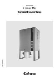
3 Overview of the <strong>Condair</strong> <strong>Dual</strong> Hybrid Humidifier<br />
3.1 Basic design of the <strong>Condair</strong> <strong>Dual</strong> Hybrid Humidifier<br />
1 Control unit<br />
2 Power supply<br />
3 Control or sensor signal input<br />
4 Connector for external safety circuit<br />
5 Options (to be installed inside the control unit):<br />
Remote operating and fault indication (Z401/Z401S)<br />
RS232 serial interface (option Z404)<br />
RS485 serial interface (option Z405)<br />
6 Shut-off valve (by customers)<br />
7 Filter (by customers, max. mesh width 0.125 mm)<br />
8 Connector (G 1/2") for fully demineralized water<br />
9 Booster pump<br />
10 Minimum pressure switch<br />
11 Excess temperature switch of pump<br />
12 Silver ionization unit<br />
8<br />
1<br />
2<br />
3<br />
4<br />
5<br />
6<br />
7<br />
9<br />
M E 20<br />
10<br />
8<br />
11<br />
22<br />
23a<br />
12<br />
18<br />
21<br />
19<br />
23b<br />
13 Drain with siphon trap (by customers)<br />
14 Drain valve<br />
15 Conductance sensor<br />
16 Connector box with 2 spray valves (3-step)<br />
Connector box with 3 spray valves (7-step,<br />
option Z407)<br />
17 Maximum pressure switch<br />
18 Spray valves<br />
19 Duct drains with siphon trap (by customers)<br />
20 Post-evaporation elements (porous ceramics)<br />
21 Spray nozzles<br />
22 Air filter min. F6/EU6 (by customers)<br />
23a Drain valves (only with option Z409)<br />
23b Water jet pump (only with option Z409)<br />
24 Water tub or floor drain (by customers)<br />
17<br />
16<br />
15<br />
14<br />
13<br />
19<br />
24
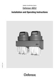
3.2 Function<br />
Spray valve Y6<br />
Spray valve Y7<br />
Capacity [%]<br />
100<br />
0<br />
0<br />
0<br />
From the reversing osmosis system (RO system) the fully demineralized<br />
water (also called permeate) is fed to the booster pump (9) via a shut-off<br />
valve (7) and a filter (8). Depending on the current output requirements the<br />
booster pump increases the water pressure to the required operating<br />
pressure of approximately 7 bars (yield load).<br />
From the booster pump the fully demineralized water is fed to the connector<br />
box (16), either directly (on systems for exhaust air cooling) or via the silver<br />
ionization unit (12) which degerminates the water.<br />
If humidification is required, one or both spray valves (18) of the connector<br />
box are opened, depending on the current humidification requirements (if<br />
the optional third spray valve is available, the system opens one, two or all<br />
three valves at a time).<br />
The fully demineralized water is now fed to the respective spray nozzles<br />
(21) producing fine aerosol fog. The air passing by the nozzles absorbs the<br />
aerosol fog thus getting humidified. Aerosol fog not absorbed by the air is<br />
retained in the post-evaporation elements (20) thus humidifying the air<br />
passing through the post-evaporation elements. Excess water is flowing<br />
down to the bottom of the post-evaporation elements and is led to the<br />
siphon trap (19), via the drain in the water tub.<br />
Control<br />
The system is controlled by an external controller or by the PI controller built<br />
into the control unit.<br />
The standard system with a 2-valve connector box provides a 3-step<br />
control corresponding to 1/3, 2/3 and 3/3 of maximum output. The first valve<br />
opens at approximately 20% and the second one at approximately 50%.<br />
If the humidification requirements reach approximately 80% both valves<br />
are open.<br />
Note: systems equipped with the optional third valve provide 7-step control<br />
with respective humidification power.<br />
Step 1 to 3<br />
0 1 2 3<br />
1<br />
0<br />
0<br />
1<br />
1<br />
1<br />
0 20 50 80 100<br />
Control signal [%]<br />
Spray valve Y6<br />
Spray valve Y7<br />
Spray valve Y8<br />
Capacity [%]<br />
0 1<br />
Monitoring<br />
The system continuously monitors the minimum and maximum pressure,<br />
the conductance of the fully demineralized water, and the temperature of<br />
the booster pump. If the conductance of the fully demineralized water<br />
exceeds the admissible range (max. 15 µS/cm), the drain valve (14) of the<br />
connector box opens and the water system is flushed until the conductance<br />
meets the preset value. An error message is displayed if the conductance<br />
value does not reach the admissible range within a certain period.<br />
100<br />
0<br />
0<br />
0<br />
0<br />
1<br />
0<br />
0<br />
2<br />
0<br />
1<br />
0<br />
Step 1 to 7<br />
3<br />
0<br />
0<br />
1<br />
4<br />
1<br />
1<br />
0<br />
5<br />
1<br />
0<br />
1<br />
6<br />
0<br />
1<br />
1<br />
7<br />
1<br />
1<br />
1<br />
0 15 27 39 51 63 75 87 100<br />
Control signal [%]<br />
9
10<br />
2 ... 10 bar<br />
Y8<br />
Y7<br />
Y6<br />
Y5<br />
Spray circle discharge (only with option Z409)<br />
Y11<br />
Y10<br />
Y9<br />
Water jet pump<br />
On systems having a central unit with spray circle discharge (option Z409)<br />
the spray circle drain valve Y5 opens after no humidification demand has<br />
occurred for 12 hours. Then, the valves Y9, Y10 and Y11 open one after the<br />
other for approximately 60 seconds to discharge each spray circle via the<br />
water jet pump.
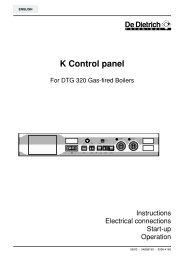
3.3 Scope of versions<br />
1 Humidification unit<br />
2 Central unit including:<br />
2a Control unit<br />
2b Permeate minimum pressure switch<br />
2c Excess temperature switch of pump<br />
2d Booster pump<br />
2e Silver ionization unit<br />
2f Permeate conductance sensor<br />
The <strong>Condair</strong> <strong>Dual</strong> Hybrid Humidifier is available in two versions: either as<br />
“centralized system” (type: CD ZE ...) or as “decentralized system”<br />
(type: CD DZ ...).<br />
In the centralized system the control unit, the booster pump, the silver<br />
ionization unit and the connector box are assembled and wired in the form<br />
of a so-called “central unit” on a mounting base or in a “Z409 protective<br />
cabinet”. In the decentralized system the above components can be fitted<br />
individually (decentralized).<br />
Centralized system (CD ZE ...)<br />
4<br />
5<br />
6<br />
3<br />
1<br />
2a<br />
2c<br />
Z409<br />
2g Connector box<br />
2h Permeate maximum pressure switch<br />
3 Electrical connectors (power supply, control or<br />
sensor signal input, connector for external<br />
safety circuit)<br />
4 Shut-off valve (by customers)<br />
5 Filter (by customers, max. mesh width 0.125 mm)<br />
6 Connector (G 1/2") for fully demineralized water<br />
2d<br />
2b<br />
2<br />
<strong>Condair</strong> <strong>Dual</strong>-S<br />
2h<br />
2g<br />
2f<br />
2e<br />
11
1 Humidification unit<br />
2a Control unit<br />
2b Permeate minimum pressure switch<br />
2c Excess temperature switch of pump<br />
2d Booster pump<br />
2e Silver ionization unit<br />
2f Permeate conductance sensor<br />
2g Connector box<br />
2h Permeate maximum pressure switch<br />
12<br />
4<br />
5<br />
6 2c<br />
Decentralized system (CD DZ ...)<br />
2d<br />
2b<br />
3<br />
2a<br />
3 Electrical connectors (power supply, control or sensor<br />
signal input, connector for external safety circuit)<br />
4 Shut-off valve (by customers)<br />
5 Filter (by customers, max. mesh width 0.125 mm)<br />
6 Connector (G 1/2") for fully demineralized water<br />
1<br />
2e<br />
2h<br />
2g<br />
2f
3.4 Options<br />
Remote operating and fault indication “Z401” and “Z401S”<br />
By means of 4 potential-free relay contacts, the remote operating and fault<br />
indication PCB (Z401: standard version, Z401S: wire breakage safe version)<br />
allows the connection of remote indicators displaying the following stages<br />
of operation: “standby”, “humidification in progress”, “maintenance due”<br />
and “error”.<br />
Note: The remote operating and fault indication PCB is supplied with<br />
separate instructions.<br />
Serial interfaces RS232 “Z404” or RS485 “Z405”<br />
The serial interface (RS232 or RS485) is used to transmit operational data<br />
from the <strong>Condair</strong> <strong>Dual</strong> Hybrid Humidifier to a PC or a building control<br />
system.<br />
Note: It is up to the customer to develop installation-specific software. Information<br />
on the communication parameters and the data format supported<br />
by the interface is available from your <strong>Condair</strong> supplier.<br />
Connector box with 3 spray valves “Z407”<br />
The connector box with 3 spray valves allows 7-step control of the <strong>Condair</strong><br />
<strong>Dual</strong> Hybrid Humidifier.<br />
Casing for central unit “Z408”<br />
The casing protects the central unit and its components from soiling and<br />
damage. The casing may be installed at any time following the installation<br />
of the humidifier.<br />
Note: The casing is supplied with separate mounting instructions.<br />
Central unit with spray circle discharge “Z409”<br />
All components of the central unit with spray circle discharge are integrated<br />
into two rugged protective cabinets. The large cabinet contains the control<br />
unit and the silver ionization. The booster pump is located below the cabinet<br />
and covered in front and on both sides by a metal apron. The small cabinet<br />
contains the connector box, the spray valves, the drain valve, the spray<br />
circle drain valves and the water jet pump. Both protective cabinets are<br />
constructed in accordance with industry standards and comply with protection<br />
class IP54.<br />
External dimensions of large cabinet (w x h x d) in cm: 60 x 60 x 21<br />
External dimensions of small cabinet (w x h x d) in cm: 50 x 30 x 21<br />
13
4 Installation and first-time commissioning<br />
4.1 Safety notes for installation and commissioning<br />
4.2 Installation of the humidification unit<br />
14<br />
– All installation and commissioning work must be performed only<br />
by adequately qualified personnel being familiar with the <strong>Condair</strong><br />
<strong>Dual</strong> Hybrid Humidifier. It is the customer’s responsibility to ensure suitable<br />
qualification.<br />
– Prior to installation work, the ventilation system (into which the <strong>Condair</strong><br />
<strong>Dual</strong> is to be incorporated) must be taken out of operation and secured<br />
against unintentional start-up.<br />
– It is mandatory to observe and comply with the instructions regarding<br />
the location and installation of particular components of the <strong>Condair</strong><br />
<strong>Dual</strong> Hybrid Humidifier (see chapters 4.2 through 4.5).<br />
– Use only the mounting accessories included in the delivery for<br />
installing the various system components. If for some special reasons<br />
an installation with the supplied installation accessories is not feasible,<br />
choose a type of installation that is equally stable. In cases of doubt,<br />
contact your <strong>Condair</strong> supplier.<br />
Important notes<br />
Usually, the design and dimensioning of the ventilation duct/monoblock as<br />
well as the location of the <strong>Condair</strong> <strong>Dual</strong> Hybrid Humidifier inside the duct<br />
are determined, recorded and set compulsory when planning the entire<br />
system. Prior to installation, however, make sure the following criteria have<br />
been taken into consideration:<br />
– Caution, fully demineralized water is aggressive! For this reason, all<br />
components located close to the humidification unit (duct/monoblock,<br />
fastening material, drain pipe, etc.) must be made of corrosion-proof<br />
steel (minimum requirements according to DIN 1.4301) or plastic.<br />
– For installation and maintenance of the humidification unit a viewing<br />
window and a sufficiently large maintenance door must be available<br />
in the duct/monoblock.<br />
– In the area of the humidification unit the ventilation duct/monoblock<br />
must be waterproof.<br />
– Important! An air filter must be installed at the air inlet of the<br />
humidification unit. The filter must meet the quality standards F6<br />
(EU6) or better.<br />
– In case of low ambient temperature the duct must be insulated to prevent<br />
the moist air from condensing inside the duct.<br />
– If the system is equipped with a heater, make sure it is at least 0.5 m<br />
away from the humidification unit.<br />
– In order to avoid drops seeping over the ceramic elements, an even<br />
air flow over the full cross section of the post-evaporation unit<br />
must be guaranteed. If necessary, rectifiers or perforated plates<br />
must be installed on the building side before the humidifier.<br />
If the air velocity in the duct before the post-evaporation unit (in<br />
relation to the humidification efficiency) exceeds 2.5 m/s, booster<br />
elements must be installed (see chapter 4.2.2).
300<br />
door<br />
360<br />
480<br />
– The section of the duct holding the humidification unit must be<br />
equipped with a sloping tub having drains before and after the<br />
post-evaporation unit (pass-through tub), or with a drain before<br />
the separation as well as drains before and after the post-evaporation<br />
unit (separated tubs). Each drain must be connected separately<br />
to the waste water system via a siphon. For hygienic reasons<br />
connect the drain pipes with an open outlet to the waste water<br />
system of the building.<br />
Note: The effective height of the siphon drain depends on the duct<br />
pressure. Correct dimensioning of the siphon drain is the customer’s<br />
responsibility.<br />
Version 1 (optimal) Version 2 (installation length optimized)<br />
Side view Side view<br />
1200 500<br />
Top view<br />
1210<br />
door<br />
min. 130<br />
min 400<br />
+ +<br />
+<br />
Heater<br />
slope min. 1°<br />
to center drain<br />
100<br />
70<br />
1200<br />
slope min. 1°<br />
to center drain<br />
Heater<br />
15
4.2.1 Installation of the nozzle system<br />
A<br />
B<br />
C<br />
D<br />
E<br />
F<br />
16<br />
Flow direction<br />
The components of the nozzle system are supplied separately and must be<br />
assembled at the installation site.<br />
The following sections explain the general installation of the nozzle system.<br />
Detailed information (dimensions, fastening points, etc.) can be found in<br />
the “installation drawing” supplied with your particular system.<br />
Important! The dimensions listed in the installation drawing are mandatory.<br />
The nozzle system comprises the following main components:<br />
A Two fixing straps for fixing the vertical mounting rails to the<br />
duct wall<br />
B Two or more horizontal mounting rails<br />
C Two vertical mounting rails, which are fixed to the duct wall<br />
with the fixing straps<br />
D A number of connection plates for fixing the horizontal mounting<br />
rails to the vertical mounting rails<br />
E One or more nozzle grids with inserted nozzles<br />
F Four or six grid bearings per nozzle grid<br />
G Two or three housing entries<br />
G
First fix the two vertical mounting rails on both sides in the duct (see<br />
installation drawing for positioning and fixing).<br />
Important! Use exclusively the fixing materials provided. If this is not<br />
possible in your case, make absolutely sure that the fixing holes are<br />
correctly sealed from the inside of the duct with suitable components.<br />
1 2 3<br />
4<br />
ø3.3 mm<br />
1. Mark the positions of the holes for the fixing straps on the duct wall and<br />
drill the ø3.3 mm holes.<br />
Important! Make sure that the fixing holes in the left and right duct wall<br />
are exactly aligned opposite each other and that the axes of the<br />
upper and lower fixing holes are at right angles to the ceiling of the<br />
duct.<br />
Then, fix the vertical mounting rails to the wall of the duct with the fixing<br />
straps and screws provided.<br />
2. Fix the connector plates to the vertical mounting rails using the screws<br />
and sliding nuts provided.<br />
3. Fix the horizontal mounting rails to the connector plates using the<br />
screws and sliding nuts provided.<br />
ø3.3 mm<br />
ø3.3 mm<br />
4. In ducts being wider than 2m:<br />
– connect all the adjacently positioned horizontal mounting rails (at<br />
the centre, if possible) using the profiled screwed connector/s<br />
provided.<br />
– mount the vertical strut/s between the horizontal mounting rails at<br />
the specified position.<br />
– mount the supplied ceiling attachment and bottom support to the<br />
duct ceiling and the duct bottom using the self-tapping screws<br />
provided (first drill the ø3.3 mm holes).<br />
17
5<br />
8<br />
18<br />
Y6 (red)<br />
Y7 (blue)<br />
Y8 (yellow)<br />
6 7<br />
B<br />
A<br />
B<br />
B<br />
5. Fix the grid bearings to the prescribed positions on the horizontal<br />
mounting rails, using the screws and sliding nuts provided.<br />
6. Mount bearing sleeve “A” and the three or five bearing bushes “B” on<br />
the nozzle grid.<br />
7. Insert the nozzle grid/s in the frames at the appropriate position/s (note<br />
numbering on the installation drawing).<br />
Note: The nozzles are provided with a protective cap Ex-works, so that<br />
no dirt can ingress. Remove these caps immediately before commissioning<br />
the system.<br />
8. Erect the housing passages (2 or 3, depending on the system) for the<br />
spray circuits: Bore the ø19mm holes and install the housing passages<br />
in accordance with the adjacent illustration.<br />
Now connect the spray circuits with the passages in accordance with<br />
the installation drawing provided. In so doing, note the following points:<br />
– The nozzles for the individual spray circuits are identified with<br />
colored bushings (red, blue and yellow).<br />
– Use only the supplied hoses ø10/8mm (outside the duct) and<br />
ø8/6mm (inside the duct). Other hoses may lead to troublesome<br />
operation.<br />
– When cutting hoses always add at least 5 mm to the specified<br />
length. This way the hoses can be fastened correctly (down to the<br />
stop) to the quick-action couplings of the nipples.<br />
Important! When cutting hoses use an appropriate tool providing<br />
straight, kink-free cuts.<br />
– Hoses must be free of kinks and other damage (longitudinal scratches,<br />
in particular).<br />
– Verify correct fastening of the hoses. Correctly mounted hoses can<br />
not be removed without pressing the locking ring.
4.2.2 Installation of the post-evaporation unit<br />
E<br />
K<br />
F<br />
G<br />
H<br />
I<br />
J<br />
Flow direction<br />
L<br />
D<br />
M<br />
B<br />
C<br />
N<br />
The components of the post-evaporation unit are supplied separately and<br />
must be assembled at the installation site.<br />
The following sections explain the general installation of the post-evaporation<br />
unit. Detailed information (dimensions, fastening points, etc.) can be<br />
found in the “installation drawing” supplied with your particular system.<br />
Important! The dimensions listed in the installation drawing are mandatory.<br />
The post-evaporation unit comprises the following main components:<br />
A<br />
A One, two or three cross arms (depending on the<br />
size of the system) each consisting of: 2 wall<br />
supports and a U-section, screwed together.<br />
B One vertical section on each side of the duct (the<br />
openings of the sections facing the duct wall).<br />
Note: The left vertical section is marked with an<br />
engraved “L” while the right vertical section carries<br />
an engraved “R”.<br />
C Two or more vertical sections “large”<br />
Note: These vertical sections are marked with an<br />
engraved “M”.<br />
D Upper flow sheets<br />
E Upper angle bracket<br />
F Upper plate sealings<br />
G Lateral flow sheets left<br />
H Lateral plate sealings<br />
I Ceramic plates (post-evaporation elements)<br />
J Lower plate sealings<br />
K Lower flow sheets<br />
L Drain-off sheets<br />
M Tub sealing<br />
N Lateral flow sheets right<br />
– Anti-drip sheets (not visible)<br />
– Lower angle bracket (not visible)<br />
19
20<br />
First attach the upper cross arm:<br />
1<br />
1. Stick the provided self-adhesive sealing plates to all wall supports.<br />
2. Stick the drilling template provided for the left and right wall supports on<br />
the wall of the duct at the correct location (see installation drawing) and<br />
drill the ø3.3 mm holes (6 holes per wall support).<br />
Important! Align the drilling templates at right angles to the roof of the<br />
duct and at the same distance from the nozzle screen.<br />
3<br />
6x<br />
158 mm<br />
3. Attach both wall supports to the wall of the duct, using the self-tapping<br />
screws provided (minimum 6 screws per wall support).<br />
Important! Before tightening the screws, check that the wall supports<br />
are at right angles to the roof of the duct and that the dimension 158 mm<br />
between the surface of the support and the duct roof is correct.<br />
4. Fit the U-section member on the wall supports and secure it to the<br />
supports with the (M6x55) cylinder head screws, washers and locking<br />
rings provided.<br />
2<br />
4<br />
104.5 mm<br />
ø3.3 mm
Mount the base plate (only systems equipped with a “Booster”):<br />
5<br />
5. If your system is equipped with a “Booster”, now mount the base plate<br />
in the tub. The base plate is attached to the tub ledge by pop rivets,<br />
behind the post evaporation unit.<br />
Important! If your system has no service door behind the post-evaporation<br />
unit, now place the booster elements in the duct, just behind the base plate.<br />
Connect two-part vertical sections:<br />
6<br />
M6x12<br />
6. For systems with two-part vertical sections first connect all sections<br />
with the connector pieces “A” (2 pcs. per connection) and the M6x12<br />
hexagon socket screws (9 pcs. per connection).<br />
21
22<br />
7<br />
7. Fix each vertical section, left and right, to the upper cross arm, using the<br />
clamping brackets, the M6x20 hexagon socket screws and the washers<br />
supplied. The two vertical sections serve as spacers when mounting<br />
the lower cross arm.<br />
Important! Before tightening the screws, push the vertical sections to<br />
the very stop towards the duct roof and align the supports parallel to<br />
the duct wall and at a right angle to the duct roof.<br />
Note: On systems with two-part vertical profiles the shorter section<br />
piece is always on top.<br />
8<br />
8. If applicable assemble the lower and middle cross arms.<br />
Important! Tighten the screws only to a point at which the wall supports<br />
can still be moved in the U-section.<br />
Note: If your system has only one cross arm proceed with step 11.
9<br />
9. Fix the lower cross arm (lowest arm on systems with three cross arms)<br />
to the two vertical sections using the clamping brackets, the M6x20<br />
hexagon socket screws and the washers supplied.<br />
Important! Before tightening the screws, align the two vertical sections<br />
parallel to the duct wall and the lower cross arm parallel to the<br />
upper cross arm. Make sure the lower cross arm is located precisely<br />
vertically below the upper cross arm.<br />
10<br />
10. Now slide the wall supports of the lower cross arm to the duct wall,<br />
check the alignment of the supporting construction once again,<br />
mark and drill the ø3.3 mm fixing holes (6 holes per wall support). Fix<br />
the wall supports to the duct wall using the self-tapping screws provided<br />
(minimum 6 screws per wall support).<br />
Note: If your system has three cross arms repeat steps 9 and 10 for<br />
mounting the middle cross arm.<br />
23
24<br />
Mounting and alignment of the vertical sections:<br />
11<br />
Drain-off<br />
sheet left<br />
50mm<br />
Drain-off sheet with system-specific<br />
width (marked with a ”V”)<br />
V<br />
Use the brackets for the upper flow sheets as<br />
spacers (the bracket with system-specific width is<br />
marked with a “V”)<br />
V<br />
Drain-off sheet right<br />
11. Use the clamping brackets to fix all vertical sections to the cross arms<br />
and temporarily align them according to the installation drawing provided.<br />
Note: Tighten the clamping brackets only to a point at which the vertical<br />
sections can still be moved.<br />
Important! The openings of the sections to the very left and right must<br />
face the duct wall.<br />
Push the vertical section to the very left towards the duct roof until it<br />
comes to a stop, then align it at a distance of 50 mm parallel to the duct<br />
wall. Finally, fasten the screws of the respective clamping brackets.<br />
50mm<br />
Hang all drain off sheets into the vertical sections and push them down<br />
to the very stop.<br />
Important! The drain-off sheet with system-specific width (marked with<br />
a “V”) must be mounted in the corresponding interstice (see installation<br />
drawing provided).
12<br />
Starting from the (already fixed) vertical section to the very left, align<br />
and fix the remaining vertical sections one after the other. Proceed as<br />
follows: push the corresponding vertical section towards the duct roof<br />
until it comes to a stop. Then, align the section parallel to the preceding<br />
section on the left by means of a bracket for the upper flow sheets.<br />
Finally, fix the screws of the respective clamping brackets.<br />
Important! At the interstice with system-specific width the bracket for<br />
the upper flow sheet marked with a “V” must be used as spacer.<br />
Important! The brackets for the upper flow sheets serve as spacers<br />
only and must not be mounted yet.<br />
50mm<br />
50mm<br />
V<br />
ø3.3 mm<br />
12. Mount the angle brackets to the upper end of all vertical sections and<br />
fix them with the M6x12 hexagon socket screws provided (slightly<br />
tighten by hand only).<br />
Align the vertical section to the very left at right angle to the cross arm.<br />
Then, push the angle bracket towards the duct roof and fix it to the duct<br />
roof using two self-tapping screws provided (drill holes ø3.3 mm<br />
before).<br />
Starting from the vertical section to the very left, align all other vertical<br />
sections one after the other and fix them with the angle brackets to the<br />
duct roof. Proceed as follows: align the corresponding section parallel<br />
to the preceding section on the left by means of a bracket for the upper<br />
flow sheets. Then, push the angle bracket to the duct roof and fix it using<br />
two self-tapping screws provided (drill holes ø3.3 mm before). Finally<br />
fasten the M6x12 hexagon socket screw in the vertical section.<br />
Important! At the interstice with system-specific width the bracket for<br />
the upper flow sheet marked with a “V” must be used as a spacer.<br />
Important! The brackets for the upper flow sheets serve as spacers<br />
only and must not be mounted yet (their final installation is explained<br />
in the following section).<br />
V<br />
50mm<br />
50mm<br />
25
26<br />
V<br />
13<br />
13. Mounting the brackets for the upper flow sheets:<br />
Starting with the narrow vertical section (left or right), align the front<br />
edge of the first bracket with the front edge of the topmost opening in<br />
the vertical section (see figure above), then fix the bracket to the duct<br />
roof using 2 (or 3, as required) self-tapping screws (drill holes ø3.3 mm<br />
before). Mount the remaining brackets in an offset order (front/rear, see<br />
figure above).<br />
Important! Mount the bracket marked with a “V” between the vertical<br />
sections with system-specific width.<br />
14<br />
V<br />
ø3.3 mm<br />
ø3.3 mm<br />
ø3.3 mm<br />
14. Fix self-adhesive sealing plates to the two remaining angle brackets<br />
(see illustration above). Use the M6x12 hexagon socket screws provided<br />
to fix the angle brackets to the lower end of the two middle vertical<br />
sections. Push angle brackets down to the duct floor, then fasten M6x12<br />
hexagon socket screws. Now fix the angle brackets to the duct floor<br />
using two self-tapping screws provided (drill holes ø3.3 mm before).<br />
Important! Depending on the slope of the tub the angle brackets may<br />
need to be fixed to the vertical sections using the extensions provided<br />
(see enlarged section in the figure above).
Install the booster elements (only on systems with “Booster”)<br />
If your system is equipped with a “Booster”, the booster elements must now<br />
be mounted.<br />
Note: If the post-evaporation unit is accessible from the back via a service<br />
door the “Booster” may be installed at the end of the installation procedure.<br />
The connector pieces and the short snap lashes are then mounted from the<br />
back. Mounting the booster at the end facilitates the installation of the<br />
ceramic plates and the ceramic angles.<br />
15<br />
15. First fix the two upper brackets to all booster elements using the thread<br />
plates and the M6x12 mm hexagon socket screws (use topmost oblong<br />
holes).<br />
Important! Tighten the screws by hand only to a point at which the<br />
brackets can still be moved.<br />
27
28<br />
16<br />
65 mm<br />
16. From the back, hang all booster elements to the upper cross arm. Use<br />
the thread plates and the M6x12 mm hexagon socket screws to fix the<br />
remaining brackets (2 or 4) to the booster elements (tighten the screws<br />
by hand only to allow later adjustment of the brackets).<br />
Couple all booster elements at the top and bottom with a connector<br />
piece and two hexagon socket screws M6x12 mm as well as with the<br />
short snap lashes (attach right below the long snap lashes).<br />
Important! When mounting the lower connector piece(s) the respective<br />
drain-off sheet(s) must be removed again.<br />
Align the “Booster” centrally, at equal distance to the left and the right<br />
duct walls.<br />
Finally push the booster elements up to a distance of 65 mm below the<br />
duct roof, then tighten the screws of the brackets.
17<br />
17. Seal all junctions between the vertical sections and the drain-off sheets<br />
with sealing compound.<br />
Install the ceramic plates<br />
Note: The installation of the ceramic plates takes place from the bottom to<br />
the top and always starts with the two rear rows to the very left and right<br />
(viewed in flow direction). Then all other rear rows (if present) are installed<br />
and finally all front rows are mounted.<br />
18<br />
18. Insert the upper and lower plate sealings into the corresponding slots<br />
of the vertical sections and push them to the top or to the bottom<br />
respectively until they come to a stop (this fixes the plate sealings in<br />
position).<br />
Important! The contact surfaces of the sealing plates must face the<br />
protruding end of the ceramic plate mounted later.<br />
Important! No lower plate sealing must be installed at the rear ceramic<br />
plates that require the installation of an anti-drip sheet (see step 21).<br />
19. Carefully push the ceramic plate (chamfered part facing the bottom)<br />
into the corresponding slot of one of the vertical sections, then tilt the<br />
plate to the back and insert it into the slot of the other vertical section.<br />
Align the ceramic element so that it protrudes for the same amount on<br />
each side.<br />
19<br />
29
30<br />
20<br />
20. Insert in the lower flow sheet between the ceramic plate and the two<br />
vertical sections (this step must be carried out only for the lowest<br />
ceramic element of a vertical row).<br />
Important! Between the vertical sections with system-specific distance<br />
the specially marked lower flow sheet must be mounted.<br />
21<br />
Air flow direction<br />
Duct, top view<br />
21. Only the rear rows of ceramic plates require the installation of<br />
anti-drip sheets. However, the anti-drip sheets must be installed<br />
only on the sides of the ceramic plates which overlap with the<br />
plates of a front row (see figure above). The ceramic plates at the<br />
very bottom require the installation of plate sealings instead of<br />
anti-drip sheets.<br />
Insert the anti-drip sheet on the corresponding side between the<br />
vertical section and the overlapping ceramic plate until it comes to a<br />
stop. Then, bend the free end of the anti-drip sheet downwards so that<br />
it forms a curve and touches the lower ceramic plate.<br />
anti-drip sheet
22<br />
22. On each side insert the two-part lateral plate sealings. Proceed as<br />
follows: first insert the lower sealing piece between the vertical section<br />
and the ceramic plate, then push it downwards until it comes to a stop.<br />
Now insert the upper sealing piece and align its top end with the upper<br />
edge of the ceramic plate.<br />
Caution: risk of injury! To prevent injury resulting from the rough<br />
ceramic plates or the lateral plate sealings use a spattle (or a similar<br />
tool) to insert the plate sealings.<br />
23. Finally, push the two upper plate sealings down until they come to a<br />
stop.<br />
Install the ceramic angle<br />
24<br />
L = 3 00 mm<br />
L = 400 mm<br />
L = 100 mm<br />
L = 300 mm<br />
L = 500 mm<br />
L = 300 mm<br />
L = 300 mm<br />
L = 700 mm<br />
24. Place the ceramic angle (one or two angles) on top of the ceramic plate.<br />
Important! The topmost ceramic plate does not require a ceramic angle.<br />
Important! Between the vertical sections with system-specific interstice<br />
the specially marked ceramic angle must be used. On systems with two<br />
ceramic angles per plate at least one angle is system-specific.<br />
Repeat steps 17 to 24 until all ceramic plates are installed. Please observe<br />
the installation sequence of the plate rows.<br />
23<br />
31
32<br />
Install the upper flow sheets:<br />
25<br />
25. Cut the supplied rubber gasket band into pieces of the appropriate<br />
length. Use the supplied hexagon socket screws M6x12 mm and the<br />
washers to fix the upper flow sheets and the rubber gaskets to the<br />
brackets already installed.<br />
Important! Between the vertical sections with system-specific interstice<br />
the upper flow sheet marked with a “V” must be used.
Install the lateral flow sheets:<br />
26<br />
ø3.3 mm<br />
26. Fix the two-part lateral flow sheets to the duct wall using the self-tapping<br />
screws provided (drill holes ø3.3 mm before). First mount the lower part<br />
of the lateral flow sheets, then the upper one (the upper part must<br />
overlap the lower one).<br />
Important! Make sure the lateral flow sheets are flush with the duct roof<br />
and the duct floor.<br />
Important! Make sure the lateral flow sheets overlap the vertical<br />
sections by a sufficient amount.<br />
Important! Make sure the lateral flow sheets are tightly screwed at<br />
every oblong hole.<br />
Finally, seal the junctions between the lateral flow sheets and the duct<br />
walls with sealing compound.<br />
33
34<br />
Install the tub seal:<br />
27<br />
27. Cut the whole length of the tub sealing to the appropriate width (width =<br />
distance between lower edge of drain-off sheet and bottom of duct plus<br />
30 mm).<br />
Then, starting on one side of the duct push the tub seal underneath the<br />
lashes of the drain-off sheets.<br />
Important! The tub seal must be installed in one piece (do not cut).<br />
Important! Make sure the tub seal tightly joins to the duct floor (adjust<br />
with knife if necessary) and verify appropriate tightness at both lateral<br />
flow sheets.
4.3 Installation of the central unit<br />
Location of the central unit<br />
– The central unit is designed for wall mounting. Make sure the construction<br />
(wall, pillar, etc.) to which the central unit is to be mounted, offers<br />
a sufficiently high load-bearing capacity and is suitable for the installation.<br />
Caution! Do not mount the central unit to vibrating parts.<br />
– The central unit must be installed only in a location having a water<br />
drain on the floor. If this is not possible, it is mandatory to provide water<br />
sensors to safely interrupt water supply in case of leakage. Furthermore,<br />
choose a suitable location that prevents damage to material<br />
assets in case of leakage.<br />
– Make sure the ambient conditions at the desired location meet the<br />
specifications outlined in chapter 8.2.<br />
– Danger of damage! Do not install the central unit in exposed locations<br />
or locations with heavy dust load. Use the optional casing (option<br />
“Z408”) to protect the central unit from damage and soiling, or use the<br />
central unit with spray circle discharge integrated in two protective cabinets<br />
(option “Z409”).<br />
– Install the central unit so that the water hoses between the connector<br />
box and the nozzles are as short as possible (max. 10 m).<br />
– Install the central unit in a freely accessible location providing enough<br />
space for operation and maintenance (0,5 m minimum clearance<br />
around the central unit, distance to floor at least 1 m).<br />
Installation of the central unit<br />
Use the provided fastening set to mount the central unit to the wall or to the<br />
monobloc. If for some special reasons an installation with the supplied<br />
fastening material is not feasible, choose a type of installation that is equally<br />
stable.<br />
Important! Use a level for accurate horizontal adjustment.<br />
900 mm<br />
640 mm<br />
ø10 mm<br />
ø8x50 mm<br />
Z408<br />
35
4.4 Installation of the components of the decentralized system<br />
36<br />
Mounting profiles for direct<br />
fastening to the monobloc<br />
560 mm<br />
260 mm<br />
500 mm<br />
400 mm<br />
Z409<br />
General notes on location and fastening<br />
– Locate the system components so that:<br />
– the distance between particular components is as short as possible<br />
and the maximum admissible distance is not exceeded.<br />
– they are freely accessible, with enough space for operation and maintenance<br />
(0,5 m minimum clearance around the components,<br />
distance to floor at least 1 m).<br />
– The booster pump, the silver ionization unit, and the connector box<br />
must be installed only in a location having a water drain on the floor.<br />
If, for any reason, this is not possible it is mandatory to provide water<br />
sensors to safely interrupt water supply in case of leakage. Furthermore,<br />
install the components in a location that prevents damage to<br />
material assets in case of leakage.<br />
– Danger of damage! Do not install the components in exposed locations<br />
or locations with excessive dust load.<br />
– The booster pump is designed for wall mounting while the control<br />
unit, the silver ionization unit, and the connector box are designed for<br />
direct fastening to the ventilation duct/monoblock. Make sure the<br />
construction (wall, pillar, housing etc.) to which the components are to<br />
be mounted, offers a sufficiently high load-bearing capacity and is suitable<br />
for the installation.<br />
Caution! Do not mount the components to vibrating parts.<br />
– Use only the provided fastening material to mount the various components.<br />
If for some special reasons an installation with the supplied<br />
fastening material is not feasible, choose a type of installation that is<br />
equally stable.
900 mm<br />
138 mm 138 mm<br />
M5x25<br />
40 mm<br />
640 mm<br />
240 mm<br />
M5x35<br />
ø10 mm<br />
ø8x50 mm<br />
M5x55<br />
M6x25<br />
M5x35<br />
Installation of the connector box<br />
Upon delivery the box is ready to be connected. Use the provided fastening<br />
material (4 pan head screws M5x55mm, 4 spring washers M5, and<br />
4 blind nuts M5) to mount the connector box directly to the ventilation duct/<br />
monoblock or to a frame.<br />
Before mounting the connector box, read the notes on correct location<br />
and make sure the length of the water hoses between the connector box<br />
and the nozzles is as short as possible (max. 10 m).<br />
Installation of the silver ionization unit<br />
Use the provided fastening material (2 pan head screws M6x25mm,<br />
2 spring washers M6, and 2 blind nuts M6) to mount the silver ionization<br />
unit directly to the ventilation duct/monoblock or to a frame.<br />
Before mounting the silver ionization unit, read the notes on correct location<br />
and make sure the length of the water hoses to the connector box and<br />
the booster pump is as short as possible (max. 10 m).<br />
Installation of the booster pump<br />
At the factory the booster pump is fastened to a mounting plate and is<br />
therefore ready to be connected as supplied. Use the provided fastening<br />
set (4 round head wood screws ø8x50mm, and 4 plugs ø10 mm) to<br />
fasten the mounting plate to a wall, a pillar, or another suitable surface.<br />
Before mounting the booster pump, read the notes on correct location<br />
and make sure the length of the water hoses between the pump and the<br />
connector box is as short as possible (max. 20 m).<br />
Installation of the control unit<br />
Use the provided fastening material (2 pan head screws M5x35mm, 1 pan<br />
head screw M5x25mm, 3 spring washers M5, and 3 blind nuts M5) to<br />
mount the control unit directly to the ventilation duct/monoblock or to a<br />
frame.<br />
Place the control unit close to the humidification unit. Before mounting the<br />
control unit, read the notes on correct location and make sure the length<br />
of the electrical wiring to the connector box, the booster pump, and the<br />
silver ionization unit is as short as possible.<br />
37
4.5 Water installation<br />
1 Shut-off valve (by customers)<br />
2 Filter (by customers, mesh width 0.125 mm)<br />
3 Connector (G 1/2", outside thread) for fully demineralized water<br />
4 Drain with siphon trap (by customers)<br />
5 Flushing conduit (ø18/16 mm or Z409: ø12/10 mm)<br />
6 Flushing connector (ø16 mm or Z409: G 1/2" outside thread)<br />
38<br />
Z409<br />
min. inner ø= 15 mm<br />
Pmin= 2 bar (working pressure)<br />
Pmax=10 bar<br />
Tmax= 45 °C<br />
Conductance 0.5...15.0 µS/cm<br />
1<br />
6 (G 1/2")<br />
3 (G 1/2")<br />
G 1/2"<br />
2<br />
Water installation of the centralized system<br />
The following illustration shows the water installation of the centralized<br />
system. Installations to be carried out are highlighted in grey.<br />
Important! Read and observe the notes on water installation at the end<br />
of the current chapter.<br />
3<br />
8<br />
9<br />
8<br />
6 (ø16 mm)<br />
5<br />
4<br />
ø= 10 mm<br />
Lmax= 10 m<br />
7 Nozzle system connectors<br />
8 Spray lines (ø10 mm)<br />
9 Central unit<br />
7<br />
Y6<br />
Y7<br />
Y8
min. inner ø= 15 mm<br />
Pmin= 2 bar (working pressure)<br />
Pmax=10 bar<br />
Tmax= 45 °C<br />
Conductance 0.5...15.0 µS/cm<br />
1<br />
G 1/2"<br />
2<br />
3<br />
1 Shut-off valve (by customers)<br />
2 Filter (by customers, mesh width 0.125 mm)<br />
3 Connector (G 1/2", outside thread) for fully demineralized water<br />
4 Drain with siphon trap (by customers)<br />
5 Flushing conduit (ø18/16 mm)<br />
6 Flushing connector (ø16 mm)<br />
10<br />
Water installation of the decentralized system<br />
The following illustration shows the water installation of the decentralized<br />
system. Installations to be carried out are highlighted in grey.<br />
Important! Read and observe the notes on water installation at the end<br />
of the current chapter.<br />
9<br />
8<br />
ø= 10 mm<br />
Lmax= 10 m<br />
6<br />
(ø16 mm)<br />
ø= 12 mm<br />
7 Nozzle system connectors<br />
8 Spray lines (ø10 mm)<br />
9 Booster pump<br />
10 Control unit<br />
11 Connector box<br />
12 Silver ionization<br />
5<br />
4<br />
7<br />
Y6<br />
Y7<br />
Y8<br />
11<br />
ø= 12 mm<br />
12<br />
39
40<br />
Notes on water installation<br />
– The installation of the shut-off valve and the filter (maximum mesh<br />
width 0.125 mm) in the fully demineralized water supply conduit is<br />
mandatory. If possible, both assemblies are to be installed close to the<br />
booster pump.<br />
Before joining the fully demineralized water supply conduit to the water<br />
connector, flush the conduit thoroughly for at least 10 minutes.<br />
If the water pressure is >10 bar, install a pressure reducing valve (set<br />
to 10 bar) in the supply conduit.<br />
– If the conduit length between the water conditioning unit and the <strong>Condair</strong><br />
<strong>Dual</strong> exceeds 20 m, the supply conduit must be equipped with a suitable<br />
pressure damper (overflow valve, surge tank, etc.). Furthermore, the<br />
supply conduit must be properly fastened according to the regulations.<br />
– The drain hose is fed from the connector box or from the corresponding<br />
connection of the protective cabinet (Z409) down into a drain conduit<br />
with siphon trap. Use a hose clamp to attach the drain hose to the<br />
nipple of the connector box. Prevent the drain hose from slipping out<br />
of the funnel by fastening it with appropriate means right above the<br />
funnel (without reducing the diameter of the hose).<br />
– Observe the following notes on correct installation of the hoses:<br />
– Use the supplied black plastic hoses ø8/6 mm, ø10/8 mm and<br />
ø12/10 mm only. For hygienic reasons do not use other hoses<br />
(except products supplied by Axair).<br />
Caution! Fully demineralized water is aggressive. For this reason,<br />
the entire water system must contain fully demineralized water<br />
resistant material only.<br />
– When cutting hoses use an appropriate cutting tool providing<br />
straight, kink-free cuts.<br />
Caution! After cutting the tubes the sharp cutting edge must be<br />
trimmed otherwise the couplings may be damaged.<br />
– Hoses must be free of kinks and other damage (longitudinal scratches,<br />
in particular).<br />
– When cutting hoses always add at least 5 mm to the required length.<br />
This way the hoses can be fastened correctly (down to the stop) to<br />
the quick-action couplings of the nipples.<br />
– Make sure the hoses are not kinked and pay attention to the minimum<br />
bend radius of 100 mm.<br />
– Do not lead hoses past hot system components (max. ambient<br />
temperature is 40 °C).<br />
– To prevent damage we strongly recommend leading the hoses<br />
inside a duct (or a similar means of protection) between the connector<br />
box and the openings of the casing.<br />
– After installation verify correct fastening of all hoses. Correctly mounted<br />
hoses can not be removed without pressing the locking ring.
Water quality requirements<br />
The fully demineralized water must meet the following requirements:<br />
– Working pressure at maximum humidification capacity: min. 2 bar<br />
– Maximum admissible inlet temperature: 45 °C<br />
– No additives (such as chlorine, disinfecting agents, ozone, etc.)<br />
– Max. germ count at the water inlet on the <strong>Condair</strong> <strong>Dual</strong>: 1000 cfu/ml<br />
– Conductance of the supply water: 0.5 ... 15.0 µS/cm<br />
41
4.6 Electrical installation<br />
F2<br />
Q<br />
Ag Silver ionization<br />
B1 Active controller<br />
B2 Passive controller<br />
F1 Fuse 2A slow-blow (control)<br />
F2 Fuse 10A slow-blow (power supply)<br />
F3 Fuse 6.3A slow-blow (booster pump)<br />
H2 Remote operating and fault indication<br />
(option Z401 or Z401S–wire breakage safe)<br />
H3 Silver ionization sub-PCB<br />
H4 Serial interface RS232/RS485<br />
(option Z404/Z405)<br />
J1 Jumper (to be installed if no monitoring devices<br />
are connected to terminal X21)<br />
42<br />
All work concerning the electrical installation must be performed only<br />
by adequately qualified personnel (electrician or specialist with equivalent<br />
training).<br />
Please observe all local regulations concerning the electrical installation.<br />
Wiring diagram (also found on the cover of the control unit)<br />
The following wiring diagram provides an overview of the electrical installation.<br />
The diagram applies to both versions of the humidification system.<br />
The terminals X1 to X26 are located below the cover of the control unit<br />
(fastened with 3 screws). The terminals accept the following maximum<br />
cable cross sections: stranded wire 1.5 mm2 , solid copper wire 2.5 mm2 .<br />
X1<br />
1 2 3 4 X21 X22<br />
X23<br />
123456789<br />
L1 N N L N 12 123456 12345678<br />
L1 NPE<br />
L1 N<br />
M1<br />
H2 (Z401S)<br />
1<br />
F3<br />
2<br />
3<br />
4<br />
H2 (Z401)<br />
J1<br />
H2<br />
1 ERR = “Error”<br />
2 SER = “Maintenance”<br />
3 STM = “Operation”<br />
4 ON = “On”<br />
24VSIK<br />
K1<br />
F1<br />
Y5<br />
Y6<br />
Y7<br />
Y8<br />
24VSIK<br />
P<<br />
PS2<br />
TS2<br />
P><br />
PS3<br />
24VDC<br />
LF<br />
X25<br />
123<br />
X24<br />
X26<br />
12 12<br />
K1 External safety circuit (maximum hygrostat,<br />
flow control, release, power-off etc.)<br />
LF Conductance sensor<br />
M1 Booster pump<br />
PS2 Permeate minimum pressure switch<br />
PS3 Permeate maximum pressure switch<br />
TS2 Excess temperature switch of pump<br />
Q External service switch or plug-in connector<br />
Y6-Y8 Spray valves connector box<br />
Y5 Drain valve connector box<br />
ZE Central unit<br />
ZE<br />
Ag<br />
H3<br />
+9VDC<br />
+Input<br />
–GND<br />
+ -<br />
Y<br />
+9VDC<br />
+Input<br />
–GND<br />
1 2 3<br />
H4<br />
B1<br />
B2
Electrical installation of centralized systems<br />
The electrical installation of centralized systems includes (also see wiring<br />
diagram):<br />
Designation/Description Cable specification<br />
Connection of the power supply to terminal X1. The service switch Q and the<br />
fuse F2 are mandatory.<br />
Caution! Make sure the voltage indicated on the rating plate meets the local line<br />
voltage. Otherwise, do not connect the control unit.<br />
Connection of the external safety circuit (maximum hygrostat, flow control,<br />
release circuit, etc.) to terminal X21.<br />
Important! If no monitoring devices are connected to terminal X21, a jumper<br />
(J1) must be installed to the terminal.<br />
Connection of an external controller or humidity sensor to terminal X25.<br />
(admissible signal values see chapter 8.1 “Specifications”).<br />
The shielding of the control signal must be connected to terminal X25/3.<br />
Caution! If the shielding of the control signal is already connected to a potential<br />
or a grounded conductor, do not connect it to terminal X25/3.<br />
min. cross section 1.5 mm 2<br />
min. cross section 0.5 mm 2<br />
shielded cable<br />
min. cross section 0.25 mm 2<br />
Electrical installation of decentralized systems<br />
The electrical installation of decentralized systems includes (also see wiring<br />
diagram):<br />
Designation/Description Cable specification<br />
Connection of the power supply to terminal X1. The service switch Q and the<br />
fuse F2 are mandatory.<br />
Caution! Make sure the voltage indicated on the rating plate meets the local line<br />
voltage. Otherwise, do not connect the control unit.<br />
min. cross section 1.5 mm 2<br />
Connection of the booster pump to terminal X1. min. cross section 1.5 mm 2<br />
Connection of the external safety circuit (maximum hygrostat, flow control,<br />
release circuit, etc.) to terminal X21.<br />
Important! If no monitoring devices are connected to terminal X21, a jumper<br />
(J1) must be installed to the terminal.<br />
min. cross section 0.5 mm 2<br />
Connection of the solenoid valves Y6-Y8 (on connector box) to terminal X22. min. cross section 0.5 mm 2<br />
Connection of minimum pressure switch PS2 (on booster pump), maximum<br />
pressure switch PS3 (on connector box), and excess temperature switch of<br />
booster pump TS2 (on connector box) to terminal X23.<br />
Connection of the conductance sensor LF (on connector box) to terminal X23.<br />
Important! For accurate measurements of the conductance the shielding must<br />
be connected to the terminal X23/7.<br />
Connection of the silver ionization to terminal X24.<br />
Connection of an external controller or humidity sensor to terminal X25.<br />
(admissible signal values see chapter 8.1 “Specifications”).<br />
The shielding of the control signal must be connected to terminal X25/3.<br />
Caution! If the shielding of the control signal is already connected to a potential<br />
or a grounded conductor, do not connect it to terminal X25/3.<br />
min. cross section 0.5 mm 2<br />
shielded cable<br />
min. cross section 0.25 mm 2<br />
min. cross section 0.5 mm 2<br />
shielded cable<br />
min. cross section 0.25 mm 2<br />
43
4.7 First-time commissioning<br />
44<br />
The following steps are carried out upon first-time commissioning:<br />
• Inspecting the installation<br />
• Flushing the water circuits<br />
• Checking the spray nozzles<br />
• Configuring the control unit or the system, respectively<br />
• Carrying out test runs<br />
• Setting up the ionization current and the capacity counter of the silver<br />
ionization according to the table in the appendix.<br />
Since first-time commissioning is always done by a service technician of<br />
your <strong>Condair</strong> supplier the current <strong>manual</strong> does not provide detailed information<br />
on this procedure.<br />
The commissioning protocol with the system configuration data can be<br />
found in chapter 9.4.
5 Operation<br />
5.1 Introduction<br />
8<br />
I/O<br />
5.2 Commissioning for daily operation<br />
test<br />
The <strong>Condair</strong> <strong>Dual</strong> Hybrid Humidifier must be commissioned and operated<br />
only by personnel familiar with the unit and adequately qualified<br />
for the task. Ascertaining the qualification is the customer’s responsibility.<br />
The <strong>Condair</strong> <strong>Dual</strong> Hybrid Humidifier is operated via the control unit. The<br />
control unit provides the following display and control elements:<br />
1<br />
XXXXXXXXXXXXXXXX<br />
XXXXXXXXXXXXXXXX<br />
M E<br />
6<br />
2 3 4 5 7<br />
1 Display<br />
(5x7 dot matrix, 2x16 characters)<br />
2 key (menu key)<br />
3 key (arrow key up)<br />
4 key (arrow key down)<br />
5 key (entry key)<br />
6 “Error” indicator (red LED)<br />
7 “Humidification on” indicator<br />
(green LED)<br />
8 key (power switch)<br />
The following description outlines the commissioning procedure for daily<br />
operation. It is assumed that first-time commissioning has been carried out<br />
properly by the service technician of your <strong>Condair</strong> supplier. Proceed as<br />
follows to prepare the <strong>Condair</strong> <strong>Dual</strong> Hybrid Humidifier for operation:<br />
• Check the installation and all system components for damage.<br />
Caution! Do not put the system into operation in case of damaged<br />
installations or system components.<br />
• Make sure the ceramic plates are correctly located and properly sealed.<br />
Caution! Put the system into operation only if the above requirements<br />
are met without fail.<br />
• Set the mains supply service switch (power supply to control unit) to<br />
“On”.<br />
• First set the power switch of the control unit to “I”, then open the shutoff<br />
valve of the water supply conduit. The control system now carries<br />
out a basic system test while the “Humidification on” and “Error”<br />
indicators light up. Once the test is completed the drain valve opens for<br />
approximately 20 seconds (flushing of the permeate conduit).<br />
45
46<br />
error XX<br />
XXXXXXXXXXXXXXXX<br />
<strong>Condair</strong> <strong>Dual</strong><br />
ready<br />
<strong>Condair</strong> <strong>Dual</strong><br />
humidific. on<br />
<strong>Condair</strong> <strong>Dual</strong><br />
flush.perm.circ.<br />
ext.safety chain<br />
interrupted<br />
error XX<br />
XXXXXXXXXXXXXXXX<br />
maintenance<br />
due<br />
Ag electrodes<br />
change due<br />
If a fault is detected during the system test, a corresponding error alert<br />
is triggered, i.e. the error indicator either flashes (alarm) or stays on<br />
(error), and a corresponding message appears on the display (also see<br />
chapter 7.1).<br />
After successful conclusion of the system test, the unit switches to<br />
standby mode and one of the following displays appears, depending<br />
on the current state of operation:<br />
– The <strong>Condair</strong> <strong>Dual</strong> is in standby mode (no humidification).<br />
– The <strong>Condair</strong> <strong>Dual</strong> humidifies (in addition, the “Humidification on”<br />
indicator lights).<br />
– Drain valve open, the permeate is led directly to the drain conduit<br />
(cause: preset flushing cycle is in progress (every 24 hrs.) or the<br />
conductance of the permeate is too high).<br />
If the external safety circuit (maximum hygrostat, flow control, etc.) is<br />
interrupted, the opposite message appears and the “Error” and “Humidification<br />
on” indicators light up intermittently.<br />
If a fault is detected during operation, a corresponding error alert is triggered,<br />
i.e. the error indicator either flashes (alarm) or stays on (error), and a<br />
corresponding message appears on the display (also see chapter 7.1).<br />
If maintenance is due or the silver ionization electrodes require replacement,<br />
the corresponding message and the current status display appear<br />
intermittently.<br />
– Maintenance due<br />
– Silver ionization electrodes worn<br />
Please consult chapter 6 for further information.<br />
Notes on operation<br />
– Make sure the minimum working pressure never drops below 2 bar<br />
during operation. In case the working pressure drops below the limit,<br />
check the reverse osmosis system and the fully demineralized water<br />
supply.<br />
– In standby mode the drain valve is opened for approximately 10<br />
seconds every 24 hours thus flushing the permeate supply conduit (for<br />
the sake of hygiene).<br />
– Humidification is not activated if the humidification request is below<br />
20% (2-valve connector box) or 15% (3-valve connector box), respectively.
5.3 Taking the humidifier out of operation<br />
To take the <strong>Condair</strong> <strong>Dual</strong> Hybrid Humidifier out of operation, e.g. for maintenance<br />
purposes, proceed as follows:<br />
• Set the power switch to “O”.<br />
• Disconnect the control unit from the mains: Set the service switch<br />
of the mains supply line to “Off”.<br />
• Close the shut-off valve of the water supply conduit.<br />
Note: If the water supply system requires maintenance depressurize<br />
the water system first. For this purpose switch the control unit back on<br />
again and wait until flushing is concluded and the alarm message<br />
no. 07 “minimum permeate pressure” appears on the display. Then,<br />
switch the control unit off again, as described above.<br />
• Mind hygiene! Let the fan of the ventilation system run until the<br />
humidification unit is dry.<br />
• In case the humidification unit requires maintenance switch the ventilation<br />
system off and secure it against unintentional power-up.<br />
Important information on extended periods of non-use<br />
Important! For reasons of hygiene, we basically recommend that the<br />
Hybrid Humidifier should be left switched on, even in periods when there<br />
is no requirement for humidification. With the system switched on, the water<br />
circuit is flushed at regular intervals and hence the build-up of germs is<br />
opposed.<br />
However, if it is necessary to leave the Hybrid Humidifier switched off for<br />
long periods, the following points should be noted:<br />
– Mind hygiene! Drain all water conduits.<br />
– For safety reasons the post-evaporation elements should remain in<br />
their working position, even if the humidifier is not used for an extended<br />
period. This prevents the water from being sprayed directly into the<br />
duct in case the humidifier is powered up inadvertently.<br />
47
5.4 Inquiring operating parameters<br />
48<br />
<strong>Condair</strong> <strong>Dual</strong><br />
ready<br />
display level<br />
perform. [kg/h]<br />
appliance: 100<br />
perform. [kg/h]<br />
appliance: 100<br />
perform. [kg/h]<br />
act.value: 33<br />
software version<br />
V6.00<br />
perform. [kg/h]<br />
appliance: 100<br />
<strong>Condair</strong> <strong>Dual</strong><br />
ready<br />
The <strong>Condair</strong> <strong>Dual</strong> provides a so-called display level used for inquiring<br />
various operating parameters. However, the display level does not let<br />
you change the parameters.<br />
Accessing the display level<br />
The <strong>Condair</strong> <strong>Dual</strong> is in standard operation mode (the display of the control<br />
unit shows the current state of operation).<br />
• Press the or key to access the display level.<br />
The opposite confirmation appears briefly on the display.<br />
Then, the first parameter of the display level shows up.<br />
Selection of parameters in the display level<br />
• Use the and keys to select the desired parameter:<br />
: next parameter<br />
: previous parameter<br />
Note: The display level is an endless loop, i.e. stepping forward from the last<br />
parameter automatically brings up the first parameter again.<br />
Quitting the display level<br />
Proceed as follows to escape from the display level:<br />
• Press the or key.<br />
The control unit returns to the status display.<br />
Note: If no key is pressed in the display level for 10 minutes, the control unit<br />
automatically returns to the status display.
M<br />
<strong>Condair</strong> <strong>Dual</strong><br />
ready<br />
or<br />
E<br />
perform. [kg/h]<br />
appliance: 100<br />
perform. [kg/h]<br />
act.value: 33<br />
unity anal.entry<br />
25 %<br />
p-pump. int/ext<br />
intern<br />
cond. permeate<br />
7 ‰S<br />
permeate limit<br />
15 ‰S<br />
perform. [kg/h]<br />
valve Y6: 35<br />
perform. [kg/h]<br />
valve Y7: 65<br />
Overview of the display level<br />
1)<br />
perform. [kg/h]<br />
valve Y8: 0<br />
2)<br />
contr.val.p-punp<br />
95 %<br />
2)<br />
3)<br />
act.val Ag curr.<br />
2.4 mA<br />
3)<br />
rem.cap.Ag elec.<br />
7 Ah<br />
Notes<br />
1) without option Z407 (third spray valve) output indication “0”<br />
2) appears only if internal permeate pump is active (“p-pump int/ext”/“intern”)<br />
3) appears only if silver ionization is active (“Ag-degermin.”/“on”)<br />
4) appears only if internal controller is active (“controller funct”“on”)<br />
next menu option<br />
previous menu option<br />
p-pump w.fl.<br />
off<br />
Ag-degermin.<br />
on<br />
elapsed time<br />
180 h<br />
maintenance due<br />
5831 h<br />
Standard operation<br />
Display level<br />
controller funct<br />
off<br />
4)<br />
nom. value rF<br />
45 %<br />
P-band<br />
10 %<br />
integr.time<br />
15 min.<br />
perform. limit<br />
100 %<br />
analog signal<br />
0-10 Vdc ( 81%)<br />
error history<br />
07/ 07/ 08/ 10<br />
software version<br />
V6.00<br />
4)<br />
4)<br />
49
50<br />
perform. [kg/h]<br />
appliance: 100<br />
perform. [kg/h]<br />
act.value: 33<br />
unity anal.entry<br />
25 %<br />
unity anal.entry<br />
25 %<br />
p-pump. int/ext<br />
intern<br />
cond. permeate<br />
7 ‰S<br />
permeate limit<br />
15 ‰S<br />
perform. [kg/h]<br />
valve Y6: 35<br />
perform. [kg/h]<br />
valve Y7: 55<br />
perform. [kg/h]<br />
valve Y8: 75<br />
contr.val.p-pump<br />
95 %<br />
Description of display level parameters<br />
The following description explains the parameters that may be accessed<br />
via the and keys once the display level has been launched (with<br />
the or key).<br />
– Maximum humidification output<br />
Maximum spraying capacity in kg/hr.<br />
– Current humidification output<br />
Current spraying capacity in kg/hr.<br />
Note: The actual spraying capacity may differ from the displayed value<br />
depending on the current spraying pressure.<br />
– Analog input (humidification request)<br />
Current signal value at the analog input in % of the maximum value.<br />
Note: If the internal controller is active the displayed value corresponds<br />
to the current ambient humidity in %rh.<br />
– Booster pump internal/external<br />
This display indicates whether the control unit is configured to work with<br />
an internal or external booster pump.<br />
– Conductance<br />
Current conductance of the permeate in µS.<br />
– Permeate limit<br />
Selected limit value of permeate conductance in µS.<br />
Note: If this value is exceeded in operation, the drain valve (Y5) of the<br />
connector box is opened until the conductance of the permeate drops<br />
below the given limit value again.<br />
– Spraying capacity of spray valve 1<br />
Nominal spraying capacity of open spray valve 1 (Y6) in kg/hr (at a<br />
spraying pressure of approximately 7 bar).<br />
– Spraying capacity of spray valve 2<br />
Nominal spraying capacity of open spray valve 2 (Y7) in kg/hr (at a<br />
spraying pressure of approximately 7 bar).<br />
– Spraying capacity of spray valve 3 (option)<br />
Nominal spraying capacity of open spray valve 3 (Y8) in kg/hr (at a<br />
spraying pressure of approximately 7 bar).<br />
Note: A nominal spraying capacity value of 0 is displayed if the optional<br />
spray valve 3 is not available.<br />
– Starting point of booster pump<br />
Starting point of the booster pump in % of the maximum humidification<br />
request.<br />
Note: This parameter is available only if the control unit is configured to<br />
work with an internal booster pump.
p-pump w.fl.<br />
off<br />
Ag degermin.<br />
on<br />
act.val Ag curr.<br />
2.4 mA<br />
rem.cap.Ag elec.<br />
7 Ah<br />
elapsed time<br />
180 h<br />
maintenance due<br />
5831 h<br />
controller funct<br />
off<br />
nom. value rH<br />
45 %<br />
P-band<br />
10 %<br />
– Booster pump on/off status while flushing<br />
This parameter indicates whether or not the booster pump runs during<br />
the flushing cycle of the permeate conduit.<br />
Note: This parameter is available only if the control unit is configured to<br />
work with an internal booster pump.<br />
– Silver ionization on/off<br />
This parameter indicates whether the silver ionization (disinfection) is<br />
activated (on) or deactivated (off).<br />
– Current of silver ionization<br />
Actual current of silver ionization in mA.<br />
Note: This parameter is available only if the silver ionization is active.<br />
– Remaining capacity of silver electrode<br />
Remaining capacity of silver electrode in Ah.<br />
Note: This parameter is available only if the silver ionization is active.<br />
– Working hour meter<br />
Working hours elapsed since first-time commissioning of the <strong>Condair</strong><br />
<strong>Dual</strong>.<br />
– Remaining time until maintenance is due<br />
Hours remaining until next maintenance is to be carried out.<br />
Note: The time displayed refers to 100% humidification output. If current<br />
operation requires less output, the maintenance intervals may be<br />
extended accordingly.<br />
Regardless of the remaining time display, a complete maintenance has<br />
to be carried out once a year (see chapter 6).<br />
– Internal controller<br />
Internal controller activated (on) or deactivated (off).<br />
Note: The internal controller may be activated from within the display<br />
level (see chapter 5.5).<br />
– Nominal value of relative humidity<br />
Preset nominal value of relative humidity in % rh.<br />
Note: This parameter is available only if the internal controller is<br />
active.<br />
– Proportional range of the internal controller<br />
Preset proportional range (P-range) of the internal controller in %.<br />
Note: This parameter is available only if the internal controller is<br />
active.<br />
51
5.5 Setting up operating parameters<br />
52<br />
intgr.time<br />
15 Min.<br />
perform. limit<br />
100 %<br />
analog signal<br />
0-10 Vdc ( 81%)<br />
error history<br />
07/ 10/ 08/ 07<br />
software version<br />
V6.00<br />
<strong>Condair</strong> <strong>Dual</strong><br />
ready<br />
entry<br />
setup level<br />
entry code<br />
9999<br />
entry code<br />
8999<br />
– Integral time of internal controller<br />
Preset integral time of the internal controller in minutes.<br />
Note: This parameter is available only if the internal controller is<br />
active.<br />
– Output limitation<br />
Preset limit value of output in % of the maximum output capacity.<br />
– Analog signal<br />
Range of the selected analog signal in V or mA, respectively.<br />
Note: The value in brackets is the current value in % of the maximum<br />
signal or the current ambient humidity in %rh, respectively.<br />
– Error history<br />
Numeric codes of the 4 most recent errors (example: “07”: last error,<br />
“10”: second to last error, etc.).<br />
Note: Information on the meaning of error codes is given in chapter 7.<br />
– Software version<br />
Current version of the control unit software.<br />
In the setup level you may adjust various operating parameters to adapt<br />
the <strong>Condair</strong> <strong>Dual</strong> Hybrid Humidifier to your particular requirements.<br />
Important! The adjustments made in the setup level immediately exercise<br />
an influence on the operating characteristics of the hybrid humidifier. Therefore,<br />
adjustments must be made only by persons having sufficient knowledge<br />
in the field of humidification and air-conditioning technology and being<br />
familiar with the <strong>Condair</strong> <strong>Dual</strong> Hybrid Humidifier.<br />
Accessing the setup level<br />
The <strong>Condair</strong> <strong>Dual</strong> is in standard operation mode (the display of the control<br />
unit shows the current operating status).<br />
• Simultaneously press the and keys to access the setup level.<br />
The opposite message is displayed briefly.<br />
You are now prompted to enter the 4-digit access code. The leftmost digit<br />
flashes.<br />
• Enter the access code “8808” as follows:<br />
Change the first digit using the and keys. Confirm your entry<br />
with the key. The next digit starts flashing.<br />
Repeat this step to change the remaining digits.
<strong>Condair</strong> <strong>Dual</strong><br />
setup level<br />
language<br />
english<br />
language<br />
english<br />
analog signal<br />
0-10 Vdc ( 81%)<br />
controller funct<br />
off<br />
language<br />
english<br />
Sprache<br />
deutsch<br />
new value<br />
deutsch<br />
old value<br />
english<br />
language<br />
english<br />
<strong>Condair</strong> <strong>Dual</strong><br />
ready<br />
Following entry of the last digit the opposite message is displayed briefly<br />
to confirm access to the setup level.<br />
Note: If you entered an erroneous code the message “incorrect code”<br />
briefly appears on the display, and subsequently you are asked to re-enter<br />
the access code.<br />
Once you have accessed the setup level, the first parameter is displayed<br />
without delay.<br />
Selection of parameters in the setup level<br />
• Use the and keys to select the desired parameter:<br />
: next parameter<br />
: previous parameter<br />
Note: The setup level is an endless loop, i.e. stepping forward from the last<br />
parameter automatically brings up the first parameter again.<br />
Changing parameters<br />
The control unit is in the setup level.<br />
• Press the key if you wish to change the current setting. The current<br />
setting starts flashing.<br />
• Press the or key to change the setting.<br />
• Confirm the new setting by pressing the key.<br />
Following confirmation of your entry, the opposite message briefly confirms<br />
the new value.<br />
Important! Wait until this message confirms the new setting before<br />
accessing the next parameter. Otherwise, the modified setting will not be<br />
stored.<br />
Note: If you press the key to confirm the current setting without modification,<br />
the opposite message is displayed briefly.<br />
Quitting the setup level<br />
Proceed as follows to escape from the setup level:<br />
• Press the key.<br />
The control unit returns to the status display.<br />
Important! All settings that have been modified and confirmed with the <br />
key before quitting the setup level are stored automatically.<br />
Note: If no key is pressed in the setup level for 10 minutes, the control unit<br />
automatically returns to the status display.<br />
53
54<br />
E<br />
<strong>Condair</strong> <strong>Dual</strong><br />
ready<br />
and<br />
entry code<br />
8808<br />
<strong>Condair</strong> <strong>Dual</strong><br />
Setup level<br />
language<br />
english<br />
analog signal<br />
0-10 Vdc ( 81%)<br />
1)<br />
cond. permeate<br />
7 ‰S<br />
language<br />
english<br />
Overview of the setup level<br />
Notes<br />
1) display of current permeate conductance<br />
2) appears only if internal controller is active (“controller funct”/“on”)<br />
next menu option<br />
previous menu option<br />
M<br />
mainten. interv.<br />
2000 h<br />
perform. limit<br />
100 %<br />
controller funct<br />
on<br />
Standard operation<br />
Setup level<br />
nom. value rh<br />
45 %<br />
P-band<br />
10 %<br />
Description of setup level parameters<br />
The following description explains all parameters that may be accessed<br />
and modified one after the other once the setup level has been launched.<br />
– Language<br />
Selection of the control unit’s dialogue language.<br />
Factory setting: English<br />
Optional settings: German, English, French, Dutch, and Danish<br />
Note: Following confirmation of the selected language the control unit<br />
switches to the appropriate language without delay.<br />
2)<br />
2)<br />
2)<br />
integr. time<br />
15 min.
analog signal<br />
0-10 Vdc ( 81%)<br />
cond. permeate<br />
7 ‰S<br />
mainten. interv.<br />
2000 h<br />
perform limit<br />
100 %<br />
controller funct<br />
off<br />
nom. value rF<br />
45 %<br />
– Analog signal<br />
Selection of the analog signal range.<br />
Factory setting: 0-10 Vdc<br />
Optional settings: 0-20 Vpa (phase-control), 0-10 Vdc, 2-10 Vdc, 0-<br />
5 Vdc (step control board), 1-5 Vdc, 0-1 Vdc,<br />
0-20 mA, 4-20 mA and 0-8.2 Vdc<br />
Note: The value in brackets is the current value in % of the maximum<br />
signal or the current ambient humidity in %rh, respectively.<br />
Caution! The signal ranges 0-20 mA and 4-20 mA must be selected<br />
only if a sensor operating at current signals is used, otherwise the control<br />
may be damaged.<br />
– Display of current permeate conductance<br />
Note: Display function only, no setting options.<br />
– Maintenance interval<br />
This setting determines in what intervals the display will be prompting<br />
you for maintenance.<br />
Factory setting: 2000 hours<br />
Optional settings: 2000, 4000, 6000, 8000 or 10000 hours<br />
– Output limitation<br />
Sets the output-limit value in % of the maximum output capacity.<br />
Factory setting: 100 %<br />
Setting range: 10 - 100 %<br />
Note: This parameter may be used to limit the maximum output in case<br />
the humidification capacity of the hybrid humidifier exceeds the current<br />
humidification requirements of the facility.<br />
– Controller function<br />
Activation (on) or deactivation (off) of the internal PI controller.<br />
Factory setting: off<br />
Optional settings: on (PI controller active), off (PI controller inactive)<br />
Caution! Do not activate the internal controller if an external controller<br />
is connected. The internal controller interprets the analog signal of the<br />
external controller as the actual humidity value captured by a sensor. If<br />
the analog signal is 0% in this case, the internal controller activates 100%<br />
humidification capacity which could lead to excessive humidification.<br />
– Nominal value of relative humidity<br />
Setting of the nominal humidity value in %rh.<br />
Note: This parameter is available only if the internal PI controller is<br />
active.<br />
Factory setting: 45 %rh<br />
Setting range: 10 - 100 %rh<br />
55
56<br />
P-band<br />
10 %<br />
integr.time<br />
15 Min<br />
– Proportional range (P-range) of the internal PI controller<br />
Sets the proportional range of the internal PI controller in %.<br />
Note: This parameter is available only if the internal PI controller is<br />
active.<br />
Factory setting: 10 %<br />
Setting range: 4 - 100 %<br />
Note: The proportional range is used to smoothen the control characteristic.<br />
The larger the selected P-range, the smoother the control<br />
characteristic will be. However, this results in a permanent control<br />
deviation, proportional to the bandwidth of the P-range. For further<br />
information please refer to chapter 9.1.<br />
– Integral time of the internal PI controller<br />
Determines the integral time of the internal PI controller in minutes.<br />
Note: This parameter is available only if the internal PI controller is<br />
active.<br />
Factory setting: 15 minutes<br />
Optional settings: off (no integral time), 2 - 100 minutes<br />
Note: The integral time setting determines the period allowed to<br />
reach the nominal humidity. Setting the integral time to the optimal<br />
value prevents the control characteristic from overshooting and, at<br />
the same time, balances the permanent deviation (caused by the<br />
proportional range setting). For further information please refer to<br />
chapter 9.1.
6 Maintenance and replacement of parts<br />
6.1 Maintenance safety instructions<br />
6.2 Important notes on maintenance<br />
– All maintenance work must be performed only by adequately<br />
qualified and trained personnel familiar with the dangers involved.<br />
Ascertaining the qualifications is the customer’s responsibility.<br />
– Instructions and details concerning the maintenance work must be<br />
observed and adhered to without fail.<br />
– Only the type of maintenance work outlined in this documentation must<br />
be carried out.<br />
– Use original <strong>Condair</strong> spare parts exclusively to replace defective parts.<br />
– Before maintenance is initiated, the hybrid humidifier must be taken<br />
out of operation in accordance with instructions in chapter 5.3<br />
and protected against unintentional switching on. Before servicing<br />
the humidification unit, the ventilation system must be set out of<br />
operation (consult the documentation of the ventilation system).<br />
The <strong>Condair</strong> <strong>Dual</strong> Hybrid Humidifier incorporates the very latest technology,<br />
and has been designed to guarantee hygienically trouble-free operation<br />
when operating conditions are observed. The hygiene during<br />
operation was tested, proven and confirmed by the award of the Fresenius<br />
Hygiene Certificate following long-term tests at the Fresenius Institute.<br />
To ensure operational safety and to guarantee hygiene in long-term<br />
operation, the maintenance concept for the <strong>Condair</strong> <strong>Dual</strong> has been<br />
structured in two stages. This differentiates between periodical checking<br />
and the implementation of a total hygiene service of the Hybrid Humidifier.<br />
Note: Axair Ltd. offers maintenance contracts. Please contact your<br />
Axair representative for an offer.<br />
57
Item Work to be carried out<br />
Nozzle system – Check the spray pattern of the spray nozzles (spray cone: optimum 90°, 60° acceptable). If necessary,<br />
clean the spray nozzles (see full servicing guide).<br />
– Check hoses and connections for sealing, if necessary, replace defective components.<br />
Post evaporation unit – Check ceramic plates for breakage. Damaged plates should be replaced (see full servicing guide).<br />
Note: A grey discoloration of the ceramic plates is normal. This is due to deposits from the silver ionization.<br />
Central unit<br />
– Silver ionization<br />
– Connection box<br />
– Booster pump<br />
Humidifier housing/<br />
Water container<br />
58<br />
Periodical checking<br />
Periodical checking should be carried out monthly and include the following<br />
steps:<br />
– Silver ionization: see detailed information in chapter 6.4.<br />
– Check the hoses and connections on the booster pump, the silver ionization and the connection box for<br />
sealing. Replace defective components where necessary.<br />
– Check the water container and humidifier housing for soiling (Rust, slime, dust), clean if necessary (see<br />
full servicing guide).<br />
– Check the water container behind the post evaporation unit for collection of residual water. If residual<br />
water is present, check the water drain and the post evaporation unit.<br />
Maintenance record – Read off the operating parameters, including “Fault history”, on the display level and enter the values on<br />
the maintenance record sheet.<br />
maintenance<br />
due<br />
Item Work to be carried out<br />
Total hygiene service of the hybrid humidifier<br />
The frequency of the implementation of a total hygiene service depends on<br />
the operating conditions. The state of the humidifier‘s hygiene and its<br />
components mostly depends on the quality of the humidifier water, the<br />
performance (and the frequency of replacement) of the filter installed<br />
before the unit, the air velocity, the air temperature, and the microbiological<br />
and chemical composition of the inlet air.<br />
The basic rule is: when the “Maintenance due” message appears, or<br />
at least once a year, the implementation of a total hygiene service is<br />
obligatory.<br />
Resetting the “Maintenance due” message<br />
Upon completion of the total hygiene service the “Maintenance due“<br />
message may be reset as follows: Make sure the control unit is switched<br />
off, then press and hold any key while switching the control unit on.<br />
Keep the key depressed (approx. 5 seconds) until the red error LED lights<br />
up briefly (approx. 1 second).<br />
Nozzle system – Switch on the individual spray circuits <strong>manual</strong>ly and check the spray pattern of the spray nozzles<br />
(spray cone: Optimum 90°, 60° permissible). Remove spray nozzles with a poor spray pattern (see Chapter<br />
6.3.2) and clean them in an ultrasonic bath.<br />
– Check hoses and connections for sealing, if necessary, replace defective components.<br />
– Check spray nozzles for secure seating. Slightly tighten loose jets with open-end spanner (width 16 mm).<br />
continued on next page
Item Work to be carried out<br />
Post evaporation unit – Check ceramic plates for breakage. Damaged plates should be replaced (see Chapter 6.3.1).<br />
– Check ceramic plates for soiling. Severely soiled plates should be replaced.<br />
Note: A grey discoloration of the ceramic plates is normal. This is due to deposits from the silver ionization.<br />
If the ceramic plates show severe deposits of dust, the ventilation system air filter should be checked for cracks,<br />
cleanliness and filter quality (min. F6 or EU6).<br />
– Check the supporting structure, the ceramic plates, the plate sealings, the flow sheets and the drainoff<br />
sheets for correct assembly and tight seating of screw connections. If necessary, install faulty<br />
components correctly (see Chapter 4.2.2) and tighten loose screw connections.<br />
Central unit<br />
– Silver ionization<br />
– Connection box<br />
– Booster pump<br />
Humidifier housing/<br />
Water container<br />
– Check the water filter in the feed line and clean if necessary.<br />
– Silver ionization: see detailed information in chapter 6.4.<br />
– Check the hoses and connections on the booster pump, the silver ionization and the connection box for<br />
sealing. Replace defective components where necessary.<br />
– Check the water container behind the post evaporation unit for collection of residual water. In the<br />
event of a substantial amount of residual water, check the water drain and post evaporation unit.<br />
Please note: drops of water and small pools of water in the water tray behind the post-evaporation unit are<br />
as a rule caused by the system.<br />
– Clean the water container and humidifier housing (also clean behind the post evaporation unit) with<br />
a combined detergent and disinfectant, e.g. “Almu 18” (available from your <strong>Condair</strong> dealer) or clean<br />
with a similar medium. Finally rinse all components with hygienically pure water (humidifier water) and rub<br />
dry.<br />
Electrical installation – Inspect connections and cables. Arrange for a qualified specialist to rectify defective installations.<br />
Humidifier water/<br />
Water treatment<br />
– Determine the bacterial count at the water connection to the central unit. In the event of bacterial count<br />
concentrations above the limit of 1000 cfu/ml (in accordance with the hygiene certificate), the water supply/<br />
water pipes must be subject to a microbiological inspection and appropriate action must be taken<br />
immediately (please contact your <strong>Condair</strong> dealer).<br />
Bacterial count concentrations in the upper area of the permitted range may be an indication of the onset<br />
of bacterial problems in the water supply. The water supply and water pipes should also be subject to a<br />
microbiological inspection.<br />
– Inspect the water treatment plant (salt available, lines sealing, conductance satisfactory?).<br />
System air – Determine the bacterial count in the supply air before the humidifier inlet. In the event of bacterial<br />
count concentrations above the limit of 1000 cfu/m 3 (in accordance with the hygiene certificate), the<br />
ventilation system must be subject to a microbiological inspection and appropriate action must be taken<br />
immediately to rectify the situation (please contact your <strong>Condair</strong> dealer).<br />
Bacterial count concentrations in the upper area of the permitted range may be an indication of the onset<br />
of bacterial problems in the ventilation system. The ventilation system should also be subject to a<br />
microbiological inspection.<br />
– Determine the bacterial count in the air at the humidifier outlet to confirm the hygienic function of the<br />
hybrid humidifier.<br />
Maintenance record – After the full servicing, read off the operating parameters, including “Fault history”, on the display level<br />
and enter the values on the maintenance record sheet. Finally, reset the servicing indicator.<br />
Notes on cleaning agents<br />
– Caution! Strictly observe the information and instructions supplied with<br />
the cleaning agents.<br />
– Caution! Do not use solvents or toxic cleaning agents.<br />
59
6.3 Removal and installation of components<br />
6.3.1 Removal and installation of ceramic plates<br />
60<br />
Removal of ceramic plates<br />
Note: If the ceramic plates of a rear row (viewed in flow direction) must be<br />
removed, the ceramic plates of the adjacent front rows must be dismantled<br />
first. The removal sequence of the ceramic plates is always from top to<br />
bottom.<br />
Proceed as follows to remove the ceramic plates of a row:<br />
1<br />
1. Loosen the screws, then remove the upper flow sheet.<br />
2. On both sides remove the two-part lateral plate sealings of the topmost<br />
ceramic plate (or the respective ceramic plate, respectively).<br />
3 4<br />
3. Push upper plate sealings upwards until they come to a stop.<br />
4. Remove the anti-drip sheet(s) (only on rear plate rows and if present).<br />
2
5 6<br />
5. Carefully pull the ceramic plate out of one vertical section, slightly tilt the<br />
plate forward, then withdraw it from the other vertical section.<br />
6. Remove the ceramic angle(s) located on top of the next ceramic<br />
element.<br />
Repeat steps 2 to 6 until all ceramic plates of a row are removed.<br />
Installation of the ceramic plates<br />
Before installation, check all ceramic plates and ceramic angles for<br />
possible damage. Damaged ceramic plates and ceramic angles must not<br />
be reinstalled.<br />
For installation of the ceramic plates proceed in the reverse order of<br />
removal (also see section “Installation of the post-evaporation elements” of<br />
chapter 4.2).<br />
Important! Make sure to reinstall the ceramic plates in the appropriate<br />
locations (according to the overview section of the installation drawing)<br />
and to install all plate sealings correctly.<br />
61
6.3.2 Removal and installation of the spray nozzles<br />
62<br />
Removal of the spray nozzles<br />
• Remove the hose(s) from the spray nozzle (press the locking ring<br />
towards screw, then pull hose off).<br />
• Squeeze the catch locks of the nozzle support and remove the support.<br />
Note: The nozzles may have different spraying capacities (max. 2 different<br />
capacities per system). Nozzles with identical capacity are marked<br />
with bushings of the same color (A). We recommend you note the<br />
positions and capacities of all nozzles before removal.<br />
• Use an open-end wrench (16 mm) to loosen and remove the nipple and<br />
the nozzle.<br />
Installation of the spray nozzles<br />
Before installation check all parts for possible damage. Damaged components<br />
must not be reinstalled.<br />
Replace all sealings of the nozzle with new ones.<br />
Important! Flush all conduits with fully demineralized water before assembling<br />
the unit.<br />
For installation proceed in the reverse order of removal.<br />
– Make sure to install the nozzles in their correct positions in the nozzle<br />
lattice (see installation drawing).<br />
– Following installation verify correct fastening of all hose connectors.<br />
Correctly mounted hoses can not be removed without pressing the<br />
locking ring.
6.4 Replacement of silver ionization “Hygieneplus”<br />
Ag electrode<br />
change due<br />
Ag electrode<br />
change due<br />
error 12<br />
Ag ion<br />
On commissioning, the current of the silver ionization must be adjusted by<br />
the technician in accordance with the table in chapter 9.4. Following the<br />
results of a germ test the settings may be changed at any time later on.<br />
If the silver ionization cartridge needs to be replaced (capacity counter<br />
reads 0) the display alternately shows the standard operation mode display<br />
and the opposite message. In case the control unit is equipped with the<br />
optional remote operation and fault indication PCB, the latter additionally<br />
issues an error. In this case it is mandatory to replace the silver<br />
ionization cartridge with a new one.<br />
If you do not reset the message “Ag electrode change due” (see below), the<br />
unit is automatically powered off after about one week of operation and the<br />
display alternately shows the two opposite messages (also refer to chapter<br />
7.1 “Error messages”).<br />
Resetting the capacity counter<br />
Following the replacement of the silver ionization cartridge the capacity<br />
counter needs to be reset as follows:<br />
Press and hold both arrow keys key while switching the control unit<br />
on. Keep both arrow keys depressed (approx. 5 seconds) until the red<br />
error LED goes off and then comes on again briefly (approx. 1 second).<br />
Replacing the silver ionization cartridge<br />
• Set the hybrid humidifier <strong>Condair</strong> <strong>Dual</strong> out of operation as per chapter<br />
5.3 and depressurize the water system.<br />
• Remove the two electrical connectors from the connections on the silver<br />
ionization cartridge.<br />
• Loosen the hose connectors at the entry and the exit, then remove both<br />
screw-in nipples.<br />
Caution! The silver ionization cartridge is filled with fully demineralized<br />
water. Place a bucket under the cartridge before loosening the connections.<br />
• Undo the four screws fastening the silver ionization cartridge to the<br />
holder, then remove the cartridge.<br />
Caution! The empty silver ionization cartridge weighs approx. 3 kg<br />
(6.5 lb).<br />
• Install the new silver ionization cartridge in the reverse order.<br />
Caution! Exhausted silver ionization cartridges must be sent to the local<br />
<strong>Condair</strong> representative for correct disposal.<br />
63
6.5 Replacement of the control unit fuses<br />
64<br />
F3 (6.3 AT)<br />
The fuses of the control unit must be replaced by authorized personnel<br />
only (e.g. electrician).<br />
Caution! Electronic components are sensitive to electrostatic discharge.<br />
Protective measures (ESD protection) must be taken before replacing the<br />
fuse(s) of the control unit.<br />
Replace fuses F1 and F3 of the control unit only with fuses matching the<br />
specifications below:<br />
– Fuse F1: fuse type: 2 A, slow-blow<br />
– Fuse F3: fuse type: 6.3 A, slow-blow<br />
Caution! Never use refurbished fuses. Do not bridge the fuse holder.<br />
F1 (2 AT)<br />
wiring diagram
7 What if ...?<br />
7.1 Error messages<br />
alarm 04<br />
limit permeate<br />
alarm 07<br />
min.press. perm.<br />
alarm 08<br />
max.press. perm.<br />
alarm 09<br />
permeate temp.<br />
Faults detected during operation trigger the fault indicator (red LED) and<br />
a corresponding event message appears on the display. The <strong>Condair</strong> <strong>Dual</strong><br />
makes a distinction between alarms and errors.<br />
Alarms<br />
An alarm indicates a temporary fault that was detected during operation<br />
(short-time interruption of the water supply) or faults that do not cause<br />
damage to the system. If the source of trouble disappears within 30<br />
minutes, the alarm is reset automatically. Otherwise, the system issues<br />
a corresponding error message.<br />
Indication: red LED flashes (once a second)<br />
alarm message appears on the display<br />
Example:<br />
Alarm message Cause/Remedy<br />
alarm 10<br />
Ag ion current<br />
alarm 09<br />
permeate temp.<br />
Cause: Permeate conductance (limit) required for stopping permeate flushing<br />
is not reached even after extended flushing.<br />
Remedy: Check reverse osmosis system.<br />
Cause: Pressure at fully demineralized water connector of booster pump is too<br />
low (cause: water conduit too narrow, reverse osmosis system too<br />
small or too many consuming devices connected to reverse osmosis<br />
system).<br />
Remedy: Check reverse osmosis system and fully demineralized water supply<br />
conduit. Pressure at fully demineralized water connector must be at<br />
least 2 bar (working pressure). Install larger supply conduits (min.<br />
inner ø 15 mm).<br />
This message appears only if the system is equipped with built-in booster pump!<br />
Cause: Admissible maximum pressure of permeate exceeded.<br />
Remedy: Check reverse osmosis system and/or setting of booster pump. Integrate<br />
a pressure regulator into the supply line.<br />
Cause: Operating temperature of booster pump is too high or flat ribbon cable<br />
between power supply PCB and CPU PCB (inside the control unit) is<br />
disconnected or defective.<br />
Remedy: Check booster pump. Plug in flat ribbon cable or replace cable, as<br />
required.<br />
Reduce temperature of fully demineralized water supply (max. 45 °C).<br />
Cause: Nominal value of ionization current not reached (cable defective or<br />
disconnected, silver electrodes worn).<br />
Remedy: Check/Re-establish electrical connection of silver ionization. Replace<br />
silver ionization cartridge (see chapter 6.4).<br />
65
Alarm message Cause/Remedy<br />
66<br />
alarm 11<br />
Ag ion test<br />
Errors<br />
An error message indicates a fault detected during operation that may<br />
cause damage to the system. If such a fault occurs, the <strong>Condair</strong> <strong>Dual</strong> is<br />
switched off automatically.<br />
Indication: red LED lights constantly<br />
error message appears on the display<br />
Example:<br />
error 10<br />
Ag ions current<br />
Example:<br />
Fault message Cause/Remedy<br />
error 01<br />
CPU<br />
error 02<br />
int.safety chain<br />
error 03<br />
analog entry<br />
Cause: At the daily Ag ion test the maximum ionization current could not be<br />
reached because the silver electrodes are partially or fully worn.<br />
Remedy: Replace silver ionization cartridge (see chapter 6.4).<br />
If the fault indicator (red LED) and the “Humidification<br />
on” indicator (green LED) light up<br />
intermittently, the external safety circuit (maximum<br />
hygrostat, flow control, etc.) is interrupted.<br />
ext.safety chain<br />
interrupted<br />
Notes:<br />
– An error message always overwrites a preceding alarm message.<br />
– The first error message remains in the display even if subsequent faults<br />
occur.<br />
Following elimination of the source of trouble the error message may be<br />
reset by switching the control unit off and back on again.<br />
Cause: Electronic component (RAM, watchdog, EPROM, EEPROM) on CPU<br />
PCB defective.<br />
Remedy: Replace CPU PCB.<br />
Cause: Internal safety circuit interrupted: power supply PCB defective, flat<br />
ribbon cable between power supply PCB and CPU PCB disconnected<br />
or defective.<br />
Remedy: Replace power supply PCB, plug in flat ribbon cable or replace cable,<br />
as required.<br />
Cause: Signal at analog input out of preset range.<br />
Remedy: Select correct range of analog signal input. Check connected sensor or<br />
controller and replace, as required.
Fault message Cause/Remedy<br />
error 05<br />
conduct. perm.<br />
error 06<br />
cond.meas. perm.<br />
error 10<br />
Ag ion current<br />
error 11<br />
Ag ion test<br />
error 12<br />
Ag ion<br />
error 13<br />
sensor<br />
Cause: Conductance limit exceeded (>100 µS/cm).<br />
Remedy: Check reverse osmosis system (max. conductance 15 µS/cm), check<br />
conductance sensor and clean, if required.<br />
Cause: Permeate conductance out of admissible range of tolerance (conductance<br />
sensor disconnected or short-circuited).<br />
Remedy: Check reverse osmosis system. Connect conductance sensor on connector<br />
box, check wiring.<br />
Cause: Nominal or maximum value of silver ionization current is not reached<br />
(error message 10 present for more than a week).<br />
Remedy: Check/plug in connection cables of silver ionization unit. Replace silver<br />
ionization cartridge. Measure ionic current at 100% humidifying capacity<br />
and compare to setup value.<br />
Cause: At the daily Ag ion test the maximum ionization current could not be<br />
reached because the silver electrodes are partially or fully worn (error<br />
message 11 present for more than a week).<br />
Remedy: Replace silver ionization cartridge (see chapter 6.4).<br />
Cause: The silver ionization cartridge was not replaced although the message<br />
“Ag electrode change due” has been present for more than a week, or<br />
the capacity counter was not reset following the replacement of the<br />
cartridge.<br />
Remedy: Replace silver ionization cartridge and/or reset the capacity counter<br />
(see chapter 6.4).<br />
Cause: If the internal controller is activated and the humidity signal of the<br />
connected humidity sensor is below 5% for more than 10 minutes the<br />
connection to the sensor is interrupted or the humidity sensor is<br />
defective.<br />
The internal controller is activated although an external controller is<br />
connected.<br />
Remedy: Check connection cable, humidity sensor and control signal setting or<br />
replace humidity sensor.<br />
Disable the internal controller if an external controller is connected.<br />
67
7.2 Failures<br />
Residual water in the section of<br />
the duct outside the water tub<br />
<strong>Condair</strong> <strong>Dual</strong> humidifies permanently<br />
Spray valves open and close<br />
continually<br />
Maximum humidification capacity<br />
is not reached<br />
Booster pump starts too late or<br />
not at all<br />
Pressure at the manometer of<br />
the connector box drops to 0<br />
bar during operation<br />
Spray valve Y6 (stage 1) and/or<br />
spray valve Y7 (stage 2) do not<br />
open<br />
68<br />
The following table presents failures that do not trigger an error message,<br />
together with indications on their cause and notes on how to eliminate the<br />
sources of trouble.<br />
Failure Cause Remedy<br />
Sealing elements improperly<br />
installed or defective.<br />
Post-evaporation elements<br />
improperly installed or ceramic<br />
plates broken.<br />
Air velocity in the duct is too high<br />
(systems without booster<br />
>2.5 m/s, systems with booster<br />
>4 m/s).<br />
Nominal value of humidity is too<br />
high.<br />
Ambient humidity very low.<br />
The internal sensor of the control<br />
unit is active although an external<br />
sensor is connected.<br />
Set nominal value correctly.<br />
Wait.<br />
Deactivate the internal sensor of<br />
the control unit (see chapter 5.5).<br />
Unstable controller signal. Check controller settings and<br />
adjust controller, as required.<br />
Output limitation active.<br />
System incorrectly dimensioned<br />
(insufficient capacity).<br />
Booster pump defective (insufficient<br />
permeate pressure).<br />
Output limitation active and/or<br />
selected starting point of booster<br />
pump is too high.<br />
Fuse F3 blown.<br />
Water hose(s) between spray valves<br />
and spray nozzles (or hoses inside<br />
the duct) disconnected.<br />
Working pressure is too low.<br />
Spray valve Y6 and/or spray valve<br />
Y7 defective.<br />
Output limitation active.<br />
Mount sealing elements correctly<br />
or replace, as required.<br />
Mount ceramic plates correctly or<br />
replace, as required.<br />
Reduce air velocity in the duct, if<br />
possible, or install booster (consult<br />
your <strong>Condair</strong> supplier beforehand).<br />
Deactivate output limitation (see<br />
chapter 5.5).<br />
Contact your <strong>Condair</strong> supplier.<br />
Replace booster pump.<br />
Deactivate output limitation (setting:<br />
100%, see chapter 5.5) and/<br />
or adjust starting point of booster<br />
pump (call service technician).<br />
Replace fuse.<br />
Attach water hose(s).<br />
Check reverse osmosis system<br />
and fully demineralized water<br />
supply conduit.<br />
Replace spray valves.<br />
Deactivate output limitation (setting:<br />
100%, see chapter 5.5).
Failure Cause Remedy<br />
Spray valve Y8 (option Z407)<br />
does not open (not even at<br />
100% humidification request).<br />
The humidifier is automatically<br />
powered down after about one<br />
week of operation.<br />
Spray valve Y8 defective or not<br />
activated in the control system.<br />
Ag ionization defective or exhausted.<br />
Capacity counter run-out.<br />
7.3 Instructions for fault elimination<br />
Contact service provider.<br />
Replace silver ionization cartridge<br />
and/or reset the capacity counter.<br />
– When eliminating faults, the <strong>Condair</strong> <strong>Dual</strong> Hybrid Humidifier must be<br />
taken out of operation (see chapter 5.3).<br />
Danger! Make sure the mains supply to the control unit is disconnected<br />
(check with voltage tester) and the shut-off valve of the water supply is<br />
closed.<br />
– Have faults eliminated by adequately qualified and trained personnel<br />
only.<br />
Malfunctions caused by the electrical installation must be repaired by<br />
authorized personnel only.<br />
– Caution! Electronic components are very susceptible to electrostatic<br />
discharge. When carrying out repairs to the control unit, appropriate<br />
measures (ESD-protection) must be taken to prevent damage to<br />
electronic components.<br />
– Malfunction of the booster pump must be remedied by your <strong>Condair</strong><br />
supplier only.<br />
69
8 Specifications/ambient conditions<br />
Type Capacity in l/hr at 7 Type Capacity in l/hr at 7<br />
bar water pressure bar water pressure<br />
Scope of versions in terms of capacity CD ZE / DZ 20 20 CD ZE / DZ 300 300<br />
CD ZE / DZ 40 40 CD ZE / DZ 400 400<br />
CD ZE / DZ 60 60 CD ZE / DZ 500 500<br />
CD ZE / DZ 80 80 CD ZE / DZ 750 750<br />
CD ZE / DZ 100 100 CD ZE / DZ 1000 1000<br />
CD ZE / DZ 120 120<br />
CD ZE / DZ 160 160<br />
CD ZE / DZ 200 200<br />
Power consumption<br />
(with booster pump)<br />
155 VA 335 VA<br />
Mains supply (to control unit) 200…240 VAC/50…60 Hz<br />
Voltage of solenoid valves (Y5-Y8) 24 VDC extra-low voltage<br />
Number of steps (humidity control) 3-step (7-step with option Z406)<br />
Resolution of humidity control 33% (14.2% with option Z406)<br />
Control accuracy 1) Control signals<br />
3-step: ±10% / 7-step (option Z406): ±4%<br />
– active 0…20 VDC (phase-control), 0…10 VDC, 0…8.25 VDC, 1…5 VDC,<br />
0…5 VDC, 0…1 VDC, 0…20 mA, 4…20 mA<br />
– passive<br />
Central unit<br />
all potentiometric humidity sensors from 1…10kΩ<br />
– Weight 18,5 kg (Z409: 39,0 kg) 22,7 kg (Z409: 43,2 kg)<br />
– Dimensions HxWxD 951 x 693 x 220 mm<br />
(Z409: 600 x 600 x 210 mm and 300 x 500 x 210 mm)<br />
Ceramic plate sizes 6<br />
Maximum air velocity in duct 2,5 m/s (without booster) 4 m/s (with booster)<br />
Max. admissible supply air temperature<br />
Water supply<br />
50 °C (before humidifier)<br />
– connector 1/2" (outside thread), nominal width 15 mm<br />
– pressure working pressure 2…10bar<br />
– water temperature max. 45 °C<br />
– water quality requirements fully demin. water 0.5...15 µS/cm (without any additives), max. 1000 cfu/ml<br />
Water drain connector (drain valve) hose stem, outer ø16 mm or G 1/2" outside thread (Z409)<br />
Water connector of humidifier plug-in system (ø10 mm)<br />
Nozzle pressure 4…10 bar<br />
Nozzle sizes 4 (2.46 l/h, 3.10 l/h, 4.0 l/h, 5.0 l/h)<br />
Monitoring of fully demineralized water min. pressure, max. pressure, conductance, temperature of booster pump<br />
Admissible ambient temperature 2) 1..40 °C<br />
Admissible ambient humidity 2) max. 75 %rh non-condensing<br />
Test and conformity certificates<br />
System of protection<br />
CE label<br />
– control IP 31<br />
– central unit IP 30<br />
– central unit in protective cabinet (Z409) IP 54<br />
Options remote operating and fault indication “Z401” or “Z401S” (wire breakage safe),<br />
RS 232/485 interface “Z404”/“Z405”,<br />
casing central unit “Z408”, central unit in protective cabinet “Z409”<br />
1) The nominal control accuracy may not always be available, because various factors (temperature control, water<br />
recycling, flap valve systems, etc.) may affect the accuracy.<br />
2) Control and central unit<br />
70
9 Appendix<br />
9.1 Notes on humidity control<br />
9.1.1 Notes on humidity control with the internal PI controller<br />
The internal PI controller of the <strong>Condair</strong> <strong>Dual</strong> Hybrid Humidifier<br />
The controller built into the <strong>Condair</strong> <strong>Dual</strong> Hybrid Humidifier is a so-called PI<br />
controller (proportional-integral controller). The PI controller interprets the<br />
analog signal as the actual humidity value captured by a sensor and<br />
controls the humidification capacity via the “proportional range” and “integral<br />
time” parameters.<br />
– Proportional range (P-range)<br />
The proportional range is used to smoothen the control characteristic.<br />
The larger the selected P-range, the smoother the control characteristic<br />
will be. However, this results in a permanent control deviation (from the<br />
preset nominal value), proportional to the bandwidth of the P-range.<br />
Note: Minor deviations may be compensated by optimal coordination<br />
with the integral time parameter.<br />
– Integral time<br />
The integral time setting determines the period allowed to balance the<br />
deviation of the control (due to the P-range) and to reach the nominal<br />
value. The greater the integral time setting, the longer it takes to reach<br />
the nominal humidity (providing better accuracy).<br />
The smaller the integral time value, the faster the nominal humidity will<br />
be reached (reduced control accuracy).<br />
Controller settings<br />
No general advice can be given on how to adjust the built-in PI controller<br />
of the <strong>Condair</strong> <strong>Dual</strong> Hybrid Humidifier (P-range and integral time settings)<br />
because every control distance (distance between humidifier and measuring<br />
spot) presents a particular degree of difficulty in terms of adjustment.<br />
However, the following rules may be used as a guideline when adjusting the<br />
PI controller:<br />
• Always start from the factory settings.<br />
• In case control requires fine-tuning:<br />
• Change values in small steps only.<br />
• Always modify the P-range first.<br />
• Never alter the P-Range and integral time settings simultaneously.<br />
71
72<br />
h,x diagram<br />
∆<br />
∆<br />
∞<br />
∞
9.1.2 Enthalpy control for <strong>Condair</strong> <strong>Dual</strong><br />
For accurate and energy saving air conditioning an enthalpy control is<br />
recommended. In simple terms, enthalpy is the amount of energy of the air<br />
in kJ/kg. With an enthalpy control the air temperature and the air humidity<br />
are used to control the preheater in a way, that the <strong>Condair</strong> <strong>Dual</strong> can be<br />
exactly and continuously regulated along the adiabatic line to the respective<br />
outlet conditions (rF2 and T2). With an enthalpy control a reheater is<br />
not needed.<br />
Important! A dew point control which uses the dew point as regulation parameter<br />
in conjunction with a preheater and an air humidifier and where the<br />
desired air temperature is achieved with a reheater is not suitable.<br />
If another control system than the enthalpy control should be used please<br />
contact your <strong>Condair</strong> representative.<br />
Example of an enthalpy control for <strong>Condair</strong> <strong>Dual</strong><br />
rF1/T1<br />
rF0/T0<br />
rF2/T2<br />
Condition of outside air (rF0/T0): -10 °C / 90 %rh<br />
Condition before humidifier (rF1/T1): 35 °C / 4 %rh<br />
Condition after humidifier (rF2/T2): 17.5 °C / 65 %rh<br />
73
Incoming air<br />
74<br />
Circulating air<br />
Mixed air<br />
Outgoing air Exhaust air<br />
Preheater<br />
Basic diagram of an enthalpy control<br />
Remark: If the temperature is changed at the preheater, the humidification<br />
of the air which can be reached by the humidifier must be adapted to the<br />
new temperature before the humidification unit. When adapting, make sure<br />
the efficiency factor of the humidifier system “η” is not exceeded<br />
according the following formula.<br />
Humidity sensor<br />
Humidity sensor<br />
Temperature sensor<br />
Temperature sensor<br />
(x2-x1) • 100<br />
η = %<br />
xS -x1<br />
Position encoder<br />
enthalpy control<br />
Hybrid humidifier <strong>Condair</strong> <strong>Dual</strong><br />
Room<br />
Control signal<br />
z.B. 0...10VDC<br />
Humidity sensor as<br />
maximum limiter
9.2 Declaration of conformity<br />
We herewith declare under our sole responsibility that the “<strong>Condair</strong> <strong>Dual</strong> 2”<br />
Hybrid Humidifiers of the “CD ZE ...” and “CD DZ ...” series comply with<br />
the standards on electromagnetic compatibility according to:<br />
EN50082-2:1995 and prEN 50082-2:1996.<br />
Axair Ltd.<br />
Pfäffikon, December 22, 1997<br />
9.3 Commissioning protocol/Maintenance record<br />
On the following two page you will find:<br />
– the “Commissioning protocol” holding the current operating parameters<br />
– the “Maintenance record” specimen (to be copied)<br />
75
<strong>Condair</strong> <strong>Dual</strong> 2<br />
Commissioning protocol<br />
/<br />
Starting point of booster pump [%]<br />
Booster pump at flushing on / off?<br />
Silver ionization off / on?<br />
Ionization current, actual / nominal value [mA]<br />
Name of test engineer<br />
Date<br />
Time<br />
Client<br />
Contact/supporter<br />
/ / / /<br />
Remaining capacity of silver electrodes [Ah]<br />
Working hours [h]<br />
Next maintenance [h]<br />
Controller on / off?<br />
Nominal humidity value (only if controller is active) [%rh]<br />
P-range (only if controller is active) [%]<br />
Integral time (only if controller is active) [min]<br />
Output limitation [%]<br />
Analog signal range<br />
Error history<br />
Software version<br />
Working pressure at full load, w/o pump [bar]<br />
Working pressure at full load, with pump [bar]<br />
Hose connectors leak-proof?<br />
Booster pump leak-proof?<br />
Nozzle connections leak-proof?<br />
Monoblock leak-proof?<br />
Routing of drain Y5 ok?<br />
Height of drain (siphon trap) at monoblock ok?<br />
Location of humidifier/internal number<br />
Type of monoblock<br />
Unit type <strong>Condair</strong> <strong>Dual</strong><br />
Serial number<br />
Location of central unit<br />
Number of control steps (3-step or 7-step)<br />
Type of control signal<br />
Measured mains voltage [V]<br />
Nominal humidification output [kg/h]<br />
Actual humidification output [kg/h]<br />
Signal at analog input [%]<br />
Booster pump internal/external?<br />
Permeate conductance [µS/cm]<br />
Permeate limit [µS/cm]<br />
Output of spray valve Y6 [kg/h]<br />
Output of spray valve Y7 [kg/h]<br />
Output of spray valve Y8 [kg/h]<br />
Notes:<br />
Page
<strong>Condair</strong> <strong>Dual</strong> 2<br />
Maintenance record<br />
Unit type Serial number Commissioning Software version Location Responsible<br />
Internal no.<br />
Signature<br />
Error history Remarks<br />
Next<br />
maintenance<br />
[h]<br />
Working<br />
hours<br />
[h]<br />
Remain. cap.<br />
silver electr.<br />
[Ah]<br />
Permeate<br />
conductance<br />
[µS/cm]<br />
Date Time H2O permeate<br />
[l]<br />
Page
9.4 Setup table silver ionization “Hygieneplus”<br />
78<br />
Setup of ionization current and capacity counter<br />
Capacity of unit [l/h] 20 30 40 60 80 100 120 125 140 160 180 200 220<br />
Type of silver ionization 30 30 60 60 125 125 125 125 250 250 250 250 250<br />
cartridge “Hygieneplus”<br />
Ionization current [mA] 1.0 1.0 1.2 1.8 2.4 3.0 3.6 3.8 4.2 4.8 5.4 5.8 6.4<br />
Capacity counter [Ah] 3.6 3.6 7.4 7.4 14.6 14.6 14.6 14.6 29.2 29.2 29.2 29.2 29.2<br />
Capacity of unit [l/h] 240 250 260 280 300 320 340 360 380 400 420 440 460<br />
Type of silver ionization 250 250 500 500 500 500 500 500 500 500 500 500 500<br />
cartridge “Hygieneplus”<br />
Ionization current [mA] 7.0 7.4 7.6 8.2 8.8 9.4 10.0 10.6 11.2 11.8 12.4 12.8 13.4<br />
Capacity counter [Ah] 29.2 29.2 58.4 58.4 58.4 58.4 58.4 58.4 58.4 58.4 58.4 58.4 58.4<br />
Capacity of unit [l/h] 480 500 550 600 650 700 750 800 850 900 950 1000<br />
Type of silver ionization 500 500 500 500 500 500 500 500 500 500 500 500<br />
cartridge “Hygieneplus”<br />
Ionization current [mA] 14.0 14.6 16.2 17.6 19.0 20.4 22.0 23.4 24.8 26.4 27.8 29.2<br />
Capacity counter [Ah] 58.4 58.4 58.4 58.4 58.4 58.4 58.4 58.4 58.4 58.4 58.4 58.4
© Axair Ltd. 2005, Printed in Switzerland<br />
Technical data subject to modification<br />
79
Reg.No. 40002-2<br />
Manufacturer:<br />
Axair Ltd.<br />
a WMH Company<br />
CH-8808 Pfäffikon (Switzerland), Talstr. 35-37, P.O. Box<br />
Telephone +41 55 416 61 11, Fax +41 55 416 62 62<br />
Internet http://www.axair.ch, E-Mail info@axair.ch<br />
Consulting, Sales and Service: