Defensor Mk5 Technical Documentation
Defensor Mk5 Technical Documentation
Defensor Mk5 Technical Documentation

Create successful ePaper yourself
Turn your PDF publications into a flip-book with our unique Google optimized e-Paper software.
1115661 EN neutral 0407<br />
Steam humidifier<br />
<strong>Defensor</strong> <strong>Mk5</strong><br />
<strong>Technical</strong> <strong>Documentation</strong>
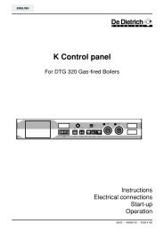
5.5.2 Wiring diagram<br />
Unit A<br />
Unit B<br />
34<br />
Supply module<br />
Control board<br />
Supply module<br />
The electrical installation is to be carried out in accordance with the following wiring diagram.<br />
F2 (1AF)<br />
F2 (1AF)<br />
JP1<br />
JP2<br />
JP1<br />
JP2<br />
Caution! Observe the installation notes in the following section.<br />
J7<br />
S1<br />
S2<br />
S4<br />
ON<br />
S3<br />
4<br />
2 3<br />
1<br />
F5<br />
(200mAF)<br />
F1 (6.3AT)<br />
F1 (6.3AT)<br />
J6<br />
J3<br />
P N P1<br />
N SK1SK2<br />
L1<br />
GND<br />
IN<br />
V+<br />
5V<br />
24V<br />
P N P1<br />
N SK1SK2<br />
L1<br />
X1 X6<br />
JP2<br />
Com-Port<br />
X1 X6<br />
J<br />
H1 (Option)<br />
K1 K2 K3 K4<br />
Steam Error Service Unit ON<br />
K1<br />
L2 L3<br />
L1<br />
200-240V / 50... 60Hz<br />
200-240V / 50... 60Hz<br />
K1<br />
1 2 3 4 5 6 7 8 9 10<br />
L2 L3<br />
L1<br />
Q3<br />
Q3<br />
F3<br />
–<br />
+<br />
F3<br />
PE<br />
L1 L2 L3<br />
PE<br />
Q4<br />
F4<br />
A1<br />
P / PI<br />
PE<br />
L1 L2 L3<br />
K3<br />
V+ IN GND<br />
B3<br />
L1 N<br />
200-240V / 50... 60Hz<br />
N<br />
L1<br />
M<br />
ϕ<br />
max.<br />
A2 140...10kΩ<br />
B2<br />
∆p<br />
set JP2<br />
to 5V<br />
Unit B Unit A<br />
V+ IN GND<br />
B1<br />
INPUT 440-500V<br />
T1 (Option)<br />
Q4<br />
set JP2<br />
to 24V<br />
A3<br />
LC-Display<br />
ON-OFF<br />
F4<br />
L2<br />
L1
Contents<br />
1 Introduction 4<br />
1.1 To the very beginning 4<br />
1.2 Notes on the technical documentation 4<br />
2 For your safety 5<br />
3 Product overview 6<br />
3.1 Unit types 6<br />
3.2 Standard delivery 7<br />
3.3 Humidification system overview 8<br />
3.4 Steam humidifier construction 8<br />
3.5 Functional description 9<br />
4 Basic planning 10<br />
4.1 Selecting the unit 10<br />
4.2 Selecting the control system 13<br />
4.3 Options 15<br />
4.4 Accessories 16<br />
4.4.1 Accessories overview 16<br />
4.4.2 Accessory details 17<br />
4.5 Additional planning instructions 19<br />
5 Mounting and installation works 20<br />
5.1 Safety instructions for mounting and installation works 20<br />
5.2 Unit fitting 20<br />
5.2.1 Humidifier location 20<br />
5.2.2 Mounting the humidifier 22<br />
5.2.3 Inspecting the installed unit 22<br />
5.3 Steam installation 23<br />
5.3.1 Positioning and mounting of the steam distribution pipes 23<br />
5.3.2 Positioning and mounting of the fan unit 26<br />
5.3.3 Installing the steam hose 27<br />
5.3.4 Installing the condensate hose 28<br />
5.3.5 Inspecting the steam installation 29<br />
5.4 Water installation 30<br />
5.4.1 Performing the water installation 30<br />
5.4.2 Inspecting the water installation 32<br />
5.5 Electric installation 33<br />
5.5.1 Electric installation overview 33<br />
5.5.2 Wiring diagram 34<br />
5.5.3 Notes on component installation 36<br />
5.5.4 Inspecting the electrical installation 39<br />
6 Operation 40<br />
6.1 Unit configuration 40<br />
6.2 Putting into operation 42<br />
6.3 Taking out of operation 43<br />
6.4 Interrogation of the operating status 44<br />
6.5 Setting the operating parameters 48<br />
6.6 Maintenance 53<br />
6.6.1 Notes on maintenance 53<br />
6.6.2 Dismantling and re-assembly work 54<br />
6.6.3 Notes on cleaning 57<br />
6.6.4 To reset the maintenance indication 57<br />
6.7 Fault elimination 58<br />
6.7.1 Fault indication 58<br />
6.7.2 What, if..? 59<br />
6.7.3 Replacing unit fuses 61<br />
6.7.4 Resetting fault indication “Error” 61<br />
7 <strong>Technical</strong> data 62
1 Introduction<br />
1.1 To the very beginning<br />
4<br />
We thank you for having purchased the steam humidifier <strong>Defensor</strong> <strong>Mk5</strong>.<br />
The steam humidifier <strong>Defensor</strong> <strong>Mk5</strong> incorporates the latest technical advances and meets all recognized<br />
safety standards. Nevertheless, improper use may result in danger to the user or third parties and/<br />
or impairment of material assets.<br />
To ensure a safe, proper, and economical operation of the steam humidifier <strong>Defensor</strong> <strong>Mk5</strong>, please<br />
observe and comply with all information and safety instructions contained in the present technical<br />
documentation.<br />
If you have questions, which are not or insufficiently answered in this documentation, please contact<br />
your <strong>Defensor</strong> supplier. They will be glad to assist you.<br />
1.2 Notes on the technical documentation<br />
Limitation<br />
The subject of this technical documentation is the steam humidifier <strong>Defensor</strong> <strong>Mk5</strong> in the versions:<br />
“Visual” and “Process”. The various accessories (humidistats, water filter, etc.) are only described insofar<br />
as this is necessary for proper operation of the equipment. Further information on accessories can be<br />
obtained in the respective instructions.<br />
This technical documentation is restricted to:<br />
– the planning of a humidifying system that is to be equipped with a steam humidifier <strong>Defensor</strong> <strong>Mk5</strong><br />
– the installation, commissioning, operation and servicing of the steam humidifier <strong>Defensor</strong> <strong>Mk5</strong><br />
The technical documentation is supplemented by various separate items of documentation (spare parts<br />
list, installation instructions for electrical installation, etc.). Where necessary, appropriate crossreferences<br />
are made to these publications in the technical documentation.<br />
Conventions<br />
This symbol draws attention to safety instructions and warnings of potential danger<br />
which, if unheeded, could result in injury to persons and/or damage to property.<br />
Safekeeping<br />
Please safeguard this technical documentation in a safe place, where it can be immediately accessed.<br />
If the equipment changes hands, the documentation should be passed on to the new operator. If the<br />
documentation gets mislaid, please contact your <strong>Defensor</strong> supplier.<br />
Language versions<br />
This technical documentation is available in various languages. Please contact your <strong>Defensor</strong> supplier<br />
for information.
2 For your safety<br />
Intended use<br />
Steam humidifiers <strong>Defensor</strong> <strong>Mk5</strong> are intended exclusively for direct or indirect room<br />
humidification or for humidification in laboratory and process applications within the<br />
specified operating conditions. Any other type of application, without the written consent<br />
of your <strong>Defensor</strong> supplier, is considered as not conforming with the intended purpose. The<br />
manufacturer/supplier cannot be made liable for any damages resulting from improper<br />
use. The user bears full responsibility.<br />
Operation of the equipment in the intended manner requires that all the information in<br />
these instructions is observed (in particular the safety instructions).<br />
General safety instructions<br />
– The steam humidifier <strong>Defensor</strong> <strong>Mk5</strong> must only be installed, operated serviced and in<br />
all cases repaired only by persons who are adequately qualified to undertake such<br />
work and are well acquainted with the product. Ascertaining the qualifications is the<br />
customer‘s responsibility.<br />
– Caution, danger of electric shock! The <strong>Defensor</strong> <strong>Mk5</strong> is operated with mains<br />
voltage. Before commencing work on the <strong>Defensor</strong> <strong>Mk5</strong>, the unit is to be rendered<br />
inoperative in accordance with section 6.3 and prevented from further inadvertent<br />
operation ( isolate unit from the electrical power supply, isolate water supply).<br />
– Observe all local safety regulations.<br />
– relating to the operation of mains-operated electrical and electronic equipment<br />
– and the provision of water, steam and electrical installations<br />
– Poorly maintained humidification systems can endanger health. The servicing intervals<br />
should therefore be adhered to without reservation and the servicing work<br />
carried out correctly.<br />
– If it is suspected that safe operation is no longer possible, then the <strong>Defensor</strong> <strong>Mk5</strong><br />
should immediately be shut down and secured against accidental power-up. This<br />
can be the case under the following circumstances:<br />
– if the <strong>Defensor</strong> <strong>Mk5</strong> is damaged<br />
– if the <strong>Defensor</strong> <strong>Mk5</strong> is no longer operating correctly<br />
– if connections and/or piping are not sealed or cables are loose<br />
– The <strong>Defensor</strong> <strong>Mk5</strong> must only be operated under the specified operating conditions<br />
(see section 7).<br />
– The <strong>Defensor</strong> <strong>Mk5</strong> is protected according to IP21. Make sure the units are installed in<br />
a drip-proof location<br />
– Caution! If the <strong>Defensor</strong> <strong>Mk5</strong> is installed in an area without a water drain, water sensors<br />
must be fitted in the area, such that in the event of leakage in the water system, the water<br />
feed is safely shut off.<br />
– Caution, danger of corrosion! In order to avoid damage, no corrosion-sensitive<br />
components should be located in the area of the aerosol streams.<br />
– No work/repair should be carried out on the <strong>Defensor</strong> <strong>Mk5</strong> other than that described in<br />
these instructions.<br />
– Use exclusively original accessories and spare parts available from your <strong>Defensor</strong><br />
supplier.<br />
– No modifications must be undertaken on the <strong>Defensor</strong> <strong>Mk5</strong> without the express<br />
written consent of Axair Ltd.<br />
5
3 Product overview<br />
3.1 Unit types<br />
6<br />
The steam humidifiers <strong>Defensor</strong> <strong>Mk5</strong> are available in 2 different type series:<br />
– Visual<br />
For direct or indirect room air humidification with standard requirements for control precision.<br />
– Process<br />
For direct or indirect room air humidification in laboratory and process applications where there<br />
are increased requirements for control precision.<br />
Basically, the devices of both type series are of the same construction except for the level control and<br />
electronics. The Visual units >10 kg/h are equipped with a combined contactor/electronic control and<br />
a level unit with a single float. To achieve a higher level of accuracy the Process units include a dedicated<br />
electronic control with special control software and are equipped with a level unit comprising two floats.<br />
They are available in versions suitable for operation with untreated water (with lime collector tank)<br />
or with fully demineralized water (without lime collector tank). All versions are equipped, as<br />
standard, with an operating and display unit, by means of which the current operating parameters can<br />
be read and the equipment configured for operation, and an integrated PI controller. The equipment<br />
can be supplied with various other options.<br />
Type overview and type designation<br />
The units of both type series are available in various versions with different steam capacities and<br />
layout of the power section (heating voltage). The following table provides an overview of the various<br />
models and their capacity ranges.<br />
<strong>Defensor</strong> <strong>Mk5</strong> Visual..-../Process..-.. Heating voltage<br />
small large Double unit large<br />
5 8 10 16 20 24 30 40 50 1) 60 1) 80 1)<br />
max. steam capacity in kg/h<br />
5.0 8.0 10.0 16.0 20.0 24.0 30.0 40.0 50.0 60.0 80.0 400V/3~/50…60Hz<br />
4.6 7.3 9.0 14.6 18.0 21.9 27.0 36.2 45.0 54.0 72.4 220V/3~/50…60Hz 2)<br />
5.1 8.4 10.3 16.7 20.6 25.1 30.6 41.5 51.4 61.7 83.1 415V/3~/50…60Hz<br />
5.1 8.7 10.3 --- --- --- --- --- --- --- --- 240V/1N~/50…60Hz<br />
5.1 8.0 10.0 --- --- --- --- --- --- --- --- 230V/1N~/50…60Hz<br />
3.9 5.8 7.1 11.6 14.3 17.4 21.5 28.8 35.7 43.0 57.7 200V/3~/50…60Hz<br />
1) <strong>Mk5</strong> ... 50 ... <strong>Mk5</strong> ... 60 ... <strong>Mk5</strong> ... 80 ...<br />
Unit A: 20 kg/h 30 kg/h 40 kg/h<br />
Unit B: 30 kg/h 30 kg/h 40 kg/h<br />
2) Process units only
The type designation is structured as follows:<br />
Designation Code<br />
Brand name <strong>Defensor</strong><br />
Product line <strong>Mk5</strong><br />
Type series – Direct or indirect room humidification Visual<br />
– Humidification for laboratory and process applications Process<br />
Operating mode – Operation with untreated water (with lime collector tank) –<br />
– Operation with fully demineralized water VE<br />
(without lime collector tank)<br />
Steam capacity in kg/h – 5, 8, 10, 16, 20, 24, 30, 40, 50, 60 or 80 ..<br />
Heating voltage – 400V/3~/50…60Hz 400V/3~<br />
– 220V/3~/50…60Hz (Process units only) 220V/3~<br />
– 415V/3~/50…60Hz 415V/3~<br />
– 240V/1N~/50…60Hz 240V/1N~<br />
– 230V/1N~/50…60Hz 230V/1N~<br />
– 200V/3~/50…60Hz 200V/3~<br />
3.2 Standard delivery<br />
The standard delivery includes:<br />
– Steam humidifier <strong>Defensor</strong> <strong>Mk5</strong> compl. (according to type designation) equipped with the desired<br />
options (remote operating and fault indication, pressure compensation kit, etc.) according to chapter<br />
4.3<br />
– Fixing set including dowels and fixing screws (for single units up to 40 kg/h), mounting profile with<br />
dowels and fixing screws (for double units 50...80 kg/h)<br />
– <strong>Technical</strong> documentation<br />
– Spare parts list (red)<br />
– Ordered accessories (steam distribution pipe, steam hose, etc.) according to chapter 4.4<br />
7
3.3 Humidification system overview<br />
7<br />
6<br />
5<br />
4<br />
3<br />
3.4 Steam humidifier construction<br />
24<br />
23<br />
22<br />
21<br />
20<br />
19<br />
18<br />
17<br />
16<br />
15<br />
14<br />
8<br />
13<br />
12<br />
11<br />
10<br />
10<br />
9<br />
8<br />
1<br />
2<br />
25<br />
26<br />
1<br />
2<br />
3<br />
4<br />
5<br />
6<br />
7<br />
8<br />
9<br />
1 Steam humidifier<br />
2 Electrical connections<br />
3 Water drainage<br />
4 Lime collector tank (only on units for operation<br />
with untreated water)<br />
5 Filter valve (accessory “Z261”)<br />
6 Water supply (building side)<br />
7 Fan unit (accessory “FAN..”)<br />
8 Condensate hose (accessory “KS10”)<br />
9 Steam hose (accessory “Z10”)<br />
10 Steam distribution pipe (accessory “81–...”)<br />
1 Housing (500 or 600)<br />
2 Power board<br />
3 Heating contactor (Visual >10 kg/h only)<br />
4 Mains contactor<br />
5 Supply module<br />
6 Control board<br />
7 Cable openings<br />
8 LC-Display<br />
9 Control keys<br />
10 Unit switch<br />
11 Drain switch<br />
12 Status indicator (LED)<br />
13 Lime collector tank (only on units for operation<br />
with untreated water)<br />
14 Drain<br />
15 Water connection<br />
16 Steam cylinder<br />
17 Drain pump<br />
18 Resistance heating element<br />
19 Inlet valve with filter<br />
20 Water supply<br />
21 Filling pipe<br />
22 Overflow pipe<br />
23 Steam outlet connector<br />
24 Water cup<br />
25 Pressure equalizing pipe<br />
26 Level unit
3.5 Functional description<br />
The <strong>Defensor</strong> <strong>Mk5</strong> steam humidifier is an unpressurized steam generator for direct (with fan unit) and<br />
indirect (with steam distribution pipe) room air humidification in ventilating and air-conditioning systems.<br />
In conjunction with a steam distribution pipe “Process” the unit may be used for humidification in<br />
laboratory and process applications.<br />
The <strong>Defensor</strong> <strong>Mk5</strong> operates on the resistance heating principle and is therefore suitable for operation<br />
with raw water, fully demineralized water and partially softened water.<br />
Water supply<br />
The water is taken via a filter valve (accessory “Z261”) to the steam humidifier. It reaches the steam<br />
cylinder via the inlet valve (level controlled) and the open water cup.<br />
Level regulation<br />
The water level in the steam cylinder is continuously monitored with the level unit. If the water level<br />
reaches a preset level (owing to the evaporation process) the level unit supplies a signal to the controller.<br />
This opens the inlet valve and the steam cylinder is filled up. When the preset operating level is reached,<br />
the level unit supplies another signal to the controller to close the inlet valve.<br />
The pressure equalizing pipe between the steam connection and the level unit ensures that the water<br />
levels are the same in the steam cylinder and the level unit.<br />
Steam generation regulation<br />
The steam is produced in the steam cylinder by several resistance heating elements. An external or the<br />
internal regulator for connection as required control the steam production fully variably from 0 to 100 %.<br />
Flushing<br />
The evaporation process increases the concentration of minerals in the water of the steam cylinder. A<br />
suitable volume of water must be flushed through the steam cylinder from time to time and replaced by<br />
fresh water to ensure that this concentration does not exceed a specific value unsuitable for operation.<br />
The <strong>Mk5</strong> steam humidifier performs an auto-adaptive flushing. This consists of the following two forms<br />
of flushing:<br />
– Automatic flushing takes place as soon as the water in the steam cylinder exceeds the upper<br />
operating level (e.g. by foaming of the water).<br />
– Flushing dependent on time performs the flushing process at preselected time intervals (see<br />
section 6.1 “Adjustments”).<br />
Automatic or time-dependent flushing takes place depending on the water quality and the operating<br />
data. If the lowest operating level is reached during the flushing process, the inlet valve remains open<br />
until the water level in the steam cylinder has reached the normal working level again. If the lowest<br />
operating level is not reached, the inlet valve is closed.<br />
Lime collector tank<br />
The minerals precipitated by the evaporation process accumulate at the bottom of the steam cylinder.<br />
Units designed for operation with untreated water are equipped with an additional lime collector tank<br />
located directly underneath the steam cylinder. This way the minerals do not accumulate in the steam<br />
cylinder but mainly in the collector tank thus extending the service intervals and reducing the<br />
maintenance costs.<br />
Units designed for operation with fully demineralized water do not have a lime collector tank as fully<br />
demineralized water contains only small amounts of minerals.<br />
9
4 Basic planning<br />
10<br />
All the data necessary for the selection and layout of a <strong>Defensor</strong> <strong>Mk5</strong> humidifier system are provided<br />
in the following chapters. The following planning steps are required:<br />
• Selecting the unit (see chapter 4.1)<br />
• Selecting the control system (see chapter 4.2)<br />
• Selecting options (see chapter 4.3)<br />
• Selecting accessories (see chapter 4.4)<br />
4.1 Selecting the unit<br />
The selection of the unit is reflected in the type description:<br />
1. Application<br />
2. Supply water quality<br />
3. Required maximum steam capacity<br />
4. Required heating voltage<br />
1. Application<br />
The type series can be selected on the basis of the following table:<br />
Scope of use Type series<br />
For direct or indirect room air humidification with<br />
standard requirements for control precision.<br />
For direct or indirect room air humidification in<br />
laboratory and process applications where there<br />
are increased requirements for control precision.<br />
Visual<br />
Process<br />
Achievable control precision<br />
– Visual: ±5 %rh (assuming optimum control distance, PI-control and use of untreated water)<br />
±2 %rh (assuming optimum control distance, PI-control and use of fully demineralized water)<br />
– Process: ±2 %rh (assuming optimum control distance, PI-control and use of untreated water)<br />
±1 %rh (assuming optimum control distance, PI-control and use of fully demineralized water)<br />
2. Supply water quality<br />
Description<br />
unit with a lime collector tank for operation with untreated<br />
water and partially softened water.<br />
Unit without a lime collector tank for operation with fully<br />
demineralized water with a conductivity value
3. Calculating the maximum required steam capacity<br />
The maximum required steam capacity is calculated from the following formulas:<br />
V • ρ<br />
m D = • (x 2 - x 1 )<br />
1000<br />
V<br />
m D = • (x 2 - x 1 )<br />
1000 • ε<br />
mD : maximum steam demand in kg/h<br />
V: volume of supply air portion per hour in m3 /h (for indirect room humidification) or room volume to<br />
be humidified per hour in m3 /h (for direct room humidification)<br />
ρ: specific gravity of air in kg/m3 ε: specific volume of air in m3 /kg<br />
x2 : desired absolute room air humidity in g/kg<br />
x1 : minimum absolute supply air humidity in g/kg<br />
The values for ρ, ε, x2 and x1 can be gathered from the h,x-diagram or the Carrier-Diagram for moist<br />
air respectively.<br />
For a rough estimate of the calculated steam capacity, the following table can be used. The values listed<br />
in the table are based on a desired room air temperature of 20°C and a desired relative room air humidity<br />
of 45 %rh.<br />
Max. portion of supply air in m 3 /hr or room max. steam<br />
volume to be humidified per hour in m 3 /hr capacity in kg/h<br />
Temperature / rel. humidity of supply air<br />
-15 °C / 90 %rh -5 °C / 80 %rh 5 °C / 60 %rh<br />
650 850 1000 5<br />
1000 1350 1600 8<br />
2000 2650 3200 16<br />
2500 3300 4000 20<br />
3000 4000 4800 24<br />
3750 5000 6000 30<br />
5000 6600 8000 40<br />
6250 8250 10000 50<br />
7500 9900 12000 60<br />
10000 13200 16000 80<br />
or<br />
<strong>Defensor</strong> <strong>Mk5</strong> Visual VE 24-400V/3~<br />
Example:<br />
Max. portion of supply air 3000 m 3 /h, temperature/<br />
rel. humidity of supply air -15°C/90%rh<br />
Important notes:<br />
– The listed formulas and values from the tables do not consider absorption or release of humidity of<br />
materials located in the room being humidified.<br />
– It is absolutely crucial to carefully calculate the maximum steam capacity. Over-dimensioned<br />
steam humidifiers interfere with the control stability.<br />
– For systems where the max. required steam capacity varies extensively (e.g. for test facilities or for<br />
systems with variable air volume flow, etc.), please contact your <strong>Defensor</strong> supplier.<br />
11
12<br />
4. Heating voltage/control voltage<br />
Heating voltage<br />
The <strong>Defensor</strong> <strong>Mk5</strong> steam humidifiers are available with various heating voltages. The maximum<br />
achievable steam capacity and the power consumption are directly dependent on the selected<br />
heating voltage (see table).<br />
B A<br />
1) Process units only<br />
<strong>Defensor</strong> <strong>Mk5</strong><br />
Visual.../Process...<br />
... 5-..<br />
... 8-..<br />
... 10-..<br />
... 16-..<br />
... 20-..<br />
... 24-..<br />
... 30-..<br />
... 40-..<br />
... 50-..<br />
... 60-..<br />
... 80-..<br />
A<br />
B<br />
A<br />
B<br />
A<br />
B<br />
400 V/3~<br />
50…60 Hz<br />
kg/h kW<br />
1)<br />
220 V/3~<br />
50…60 Hz<br />
415 V/3~<br />
50…60 Hz<br />
<strong>Defensor</strong> <strong>Mk5</strong> Visual VE 24-400V/3~<br />
240 V/1N~<br />
50…60 Hz<br />
230 V/1N~<br />
50…60 Hz<br />
200 V/3~<br />
50…60 Hz<br />
A kg/h kW A kg/h kW A kg/h kW A kg/h kW A kg/h kW A<br />
5.0 3.8 5.5 4.6 3.4 9.0 5.1 4.0 6.0 5.1 4.0 17.0 5.1 4.0 16.5 3.9 3.0 8.2<br />
8.0 6.0 8.7 7.3 5.5 14.4 8.4 6.5 9.0 8.7 6.5 27.2 8.0 6.0 26.0 5.8 4.5 13.1<br />
10.0 7.5 11.0 9.0 6.7 17.7 10.3 8.0 11.5 10.3 8.0 33.0 10.0 7.4 32.0 7.1 5.5 16.1<br />
16.0 12.0 17.4 14.6 10.9 28.7 16.7 13.0 18.1 __ __ __ __ __ __ 11.6 9.0 26.1<br />
20.0 14.9 21.5 18.0 13.5 35.4 20.6 16.0 22.3 __ __ __ __ __ __ 14.3 11.1 32.2<br />
24.0 18.1 26.2 21.9 16.4 43.1 25.1 19.5 27.2 __ __ __ __ __ __ 17.4 13.5 39.2<br />
30.0 22.3 32.3 27.0 20.2 53.1 30.6 24.0 33.5 __ __ __ __ __ __ 21.5 16.7 48.3<br />
40.0 30.0 43.3 36.2 27.2 71.4 41.5 32.3 45.0 __ __ __ __ __ __ 28.8 22.4 64.9<br />
20.0<br />
+<br />
30.0<br />
14.9<br />
+<br />
22.3<br />
21.5<br />
+<br />
32.3<br />
18.0<br />
+<br />
27.0<br />
13.5<br />
+<br />
20.2<br />
35.4<br />
+<br />
53.1<br />
20.6<br />
+<br />
30.6<br />
16.0<br />
+<br />
24.0<br />
22.3<br />
+<br />
33.5<br />
30.0<br />
+<br />
30.0<br />
22.3<br />
+<br />
22.3<br />
32.3<br />
+<br />
32.3<br />
27.0<br />
+<br />
27.0<br />
20.2<br />
+<br />
20.2<br />
53.1<br />
+<br />
53.1<br />
30.6<br />
+<br />
30.6<br />
24.0<br />
+<br />
24.0<br />
33.5<br />
+<br />
33.5<br />
40.0<br />
+<br />
40.0<br />
30.0<br />
+<br />
30.0<br />
43.3<br />
+<br />
43.3<br />
36.2<br />
+<br />
36.2<br />
27.2<br />
+<br />
27.2<br />
71.4<br />
+<br />
71.4<br />
41.5<br />
+<br />
41.5<br />
32.3<br />
+<br />
32.3<br />
45.0<br />
+<br />
45.0<br />
__ __ __ __ __ __<br />
__ __ __ __ __ __<br />
__ __ __ __ __ __<br />
14.3<br />
+<br />
21.5<br />
11.1<br />
+<br />
16.7<br />
32.2<br />
+<br />
48.3<br />
21.5<br />
+<br />
21.5<br />
16.7<br />
+<br />
16.7<br />
48.3<br />
+<br />
48.3<br />
28.8<br />
+<br />
28.8<br />
22.4<br />
+<br />
22.4<br />
64.9<br />
+<br />
64.9<br />
Should you require a unit with a different heating voltage, please contact your <strong>Defensor</strong> supplier.<br />
Control voltage<br />
<strong>Defensor</strong> <strong>Mk5</strong> steam humidifiers are designed for a standard control voltage of 220…240V/<br />
50…60Hz.<br />
If used in systems without separate control voltage supply, the <strong>Defensor</strong> <strong>Mk5</strong> may be equipped with<br />
an optional transformer 450-500 V/230 V (see chapter 4.4).
4.2 Selecting the control system<br />
The various control systems<br />
– System 1: Room humidity control<br />
System 1 is suited for direct room humidification and air conditioning systems with mainly<br />
recirculated air. The humidity sensor or humidistat respectively is preferably located in the room<br />
itself or in the exhaust air duct.<br />
A1 humidity sensor<br />
B1 B2 <strong>Mk5</strong> B3<br />
B1 ventilation interlock<br />
B2<br />
B3<br />
airflow monitor<br />
safety humidistat<br />
PII<br />
B4 humidistat<br />
PII internal continuous controller (PI-controller)<br />
PIE external continuous controller (e.g. PI-controller)<br />
PIE<br />
Y input signal from A1<br />
– System 2: Room humidity control with continuous limitation of the supply air humidity<br />
System 2 is suited for air conditioning systems with a large porion of supply air, low supply air<br />
temperature, post-humidification, or variable airflow volume. If the supply air humidity exceeds<br />
the preset value, the continuous limitation is effected prior to the room humidity control.<br />
The humidity sensor (A1) is preferably located in the exhaust air duct or in the room itself. The<br />
humidity sensor (A2) for the limitation of the supply air humidity is located in the supply air duct after<br />
the steam distribution pipe. This control system requires a external continuous controller with the<br />
option to connect a second humidity sensor.<br />
Attention! The continuous limitation of the supply air humidity is no substitute for the safety humidistat.<br />
A1/2 humidity sensor<br />
B1 ventilation interlock<br />
B2 airflow monitor<br />
B3 safety humidistat<br />
PI E<br />
external continuous controller (e.g. PI-controller)<br />
Y input signal from A1<br />
Z input signal from A2<br />
K<br />
∆p<br />
<strong>Defensor</strong><br />
ϕ<br />
max<br />
K ∆p<br />
B1 B2<br />
<strong>Defensor</strong><br />
<strong>Mk5</strong> B3<br />
PIE<br />
ϕ<br />
max<br />
A2<br />
ϕ<br />
Z<br />
B4<br />
Y<br />
Y<br />
ϕ<br />
ϕ<br />
ϕ<br />
A1<br />
ϕ<br />
A1<br />
ϕ<br />
ϕ<br />
B4<br />
13
14<br />
– System 3: Supply air humidity control<br />
Supply air humidity control (humidity sensor installed in supply air duct) should be used only<br />
where room humidity control is impracticable for technical reasons. Such systems always<br />
require a PI-controller. The humidity sensor (A1) is located in the supply air duct after the steam<br />
distribution pipe.<br />
A1 humidity sensor<br />
B1 B2 <strong>Mk5</strong> B3<br />
B1 ventilation interlock<br />
B2<br />
B3<br />
airflow monitor<br />
safety humidistat<br />
PII<br />
PII PIE Y<br />
internal continuous controller (PI-controller)<br />
external continuous controller (e.g. PI-controller)<br />
input signal from A1<br />
PIE<br />
Which humidity control system for which application?<br />
<strong>Defensor</strong><br />
Application Location of the humidity sensor<br />
Room or exhaust air duct supply air duct<br />
Air conditioning systems with:<br />
supply air portion up to 33% System 1 System 1<br />
supply air portion up to 66% System 1 or 2 System 2 or 3<br />
supply air portion up to 100% System 2 System 3<br />
Supply air humidity control ––– System 3<br />
Direct room humidification System 1 –––<br />
Please contact your <strong>Defensor</strong> supplier, if your application meets the following conditions:<br />
– Humidification of small rooms up to 200 m3 – Air conditioning systems with a high number of air exchanges<br />
– Systems with variable air volume flow<br />
– Test facilities with extreme control accuracy requirements<br />
– Rooms with a high variation in max. steam capacity<br />
– Systems with temperature fluctuations<br />
– Cold rooms and systems with dehumidification<br />
K<br />
∆p<br />
ϕ<br />
max<br />
ϕ<br />
A1<br />
Y
4.3 Options<br />
The following table presents an overview of all options which are available for the steam humidifier<br />
<strong>Defensor</strong> <strong>Mk5</strong>.<br />
<strong>Defensor</strong> <strong>Mk5</strong> Visual Process<br />
Steam capacity in kg/h 5...16 20...40 50...80 5...16 20...40 50…80<br />
Interface RS232/RS485<br />
(Interface PCB RS232/RS485 for data<br />
exchange with a building control<br />
––– RS<br />
system)<br />
number – – – 1 1 1<br />
Remote operating and fault indication<br />
(PCB with relay contacts for the connection<br />
of remote displays for “Operation”,<br />
RFS<br />
“Steam”, “Fault” and “Service”) number 1 1 1 1 1 1<br />
Pressure compensation kit up to 10’000 Pa<br />
(Assembly kit for the installation of the<br />
filling bowl on the equipment cover, for<br />
the operation of the steam humidifier in<br />
installations with duct air pressures up<br />
OVP<br />
to 10’000 Pa)<br />
number 1 1 2 1 1 2<br />
Transformer 450-500V/230V TRAF 1)<br />
(Transformer for systems without a separate<br />
control voltage supply)<br />
number 1 1 1 1 1 1<br />
Connection terminal 400-415 V/3~<br />
(Separate terminals for systems where<br />
direct connection of heating voltage to<br />
main contactor (standard version) is<br />
KLK KLG KLK KLG<br />
not permitted by local regulations) number 1 1 2 1 1 2<br />
Unit housing stainless steel S-Inox L-Inox S-Inox L-Inox<br />
1) When ordering indicate the type of unit<br />
number 1 1 2 1 1 2<br />
15
4.4 Accessories<br />
4.4.1 Accessories overview<br />
16<br />
The following table presents an overview of all accessories which are available for the steam humidifier<br />
<strong>Defensor</strong> <strong>Mk5</strong>.<br />
<strong>Defensor</strong> <strong>Mk5</strong> Visual Process<br />
Steam capacity in kg/h 5…16 20…40 50…80 5…16 20…40 50…80<br />
Steam distribution pipe<br />
(see accessory details in chapter 4.4.2)<br />
81-...<br />
number 1 2 1 2<br />
Steam distribution pipe Process<br />
(see accessory details in chapter 4.4.2)<br />
Z..<br />
number 1 2 1 2<br />
OptiSorp steam distribution system System 1 System 2 System 1 System 2<br />
(see accessory details in chapter 4.4.2)<br />
number 1 1 1 1<br />
Fan unit FAN16 FAN40 FAN16 FAN40<br />
(see accessory details in chapter 4.4.2)<br />
number 1 1 2 1 1 2<br />
Steam hose / meter Z10 (Ø54/42.4)<br />
number 1 2 1 2<br />
Steam hose 1 1/4" reinforced / meter Z250<br />
number 1 2 1 2<br />
Condensate hose / meter KS10<br />
number 1 2 1 2<br />
Filter valve Z261<br />
number 1 (per system)<br />
Mounting profile BS4 BS5 BS6 1) BS4 BS5 BS6 1)<br />
number 1 1 1 1 1 1<br />
Humidity sensor, room EGH 130<br />
number 1 (per system)<br />
Humidity sensor, duct EGH 110<br />
number 1 (per system)<br />
1) For double units the mounting profiles BS6 are included in the standard delivery
4.4.2 Accessory details<br />
Steam distribution pipes 81-... for indirect room humidification<br />
The steam distribution pipes are selected on the basis of the duct width (for horizontal installation) or<br />
the duct height (for vertical installation) and the capacity of the steam humidifier.<br />
Important! Always select the longest possible steam distribution pipe (optimum humidification distance).<br />
L<br />
B<br />
Steam distribution pipes 81-...<br />
for <strong>Defensor</strong> <strong>Mk5</strong> (CrNi steel)<br />
Duct width (B) Steam output<br />
Type Length in mm (L) 3) in mm max. in kg/h<br />
81-200 1) 200 210…400 10<br />
81-350 2) 350 400…600 30<br />
81-500 2) 500 600…750 30<br />
81-650 650 750…900 50<br />
81-800 800 900…1100 50<br />
81-1000 1000 1100…1300 50<br />
81-1200 1200 1300…1600 50<br />
81-1500 1500 1600…2000 50<br />
81-1800 1800 2000…2400 50<br />
81-2000 2000 2200…2600 50<br />
81-2300 2300 2500…2900 50<br />
81-2500 2500 2700…3100 50<br />
1) Only for units with a max. steam capacity of 10 kg/h<br />
2) Only for units with a max. steam capacity of 30 kg/h<br />
3) Special length available on request<br />
Note: If the humidification distance (see chapter 5.3.1) has to be reduced for technical reasons, the<br />
amount of steam per basic unit must be divided between two steam distribution pipes or the OptiSorp<br />
steam distribution system must be used. If this is the case, contact your <strong>Defensor</strong> supplier.<br />
Steam distribution pipe “Process” (accessory “Z...”)<br />
The steam distribution pipe “Process” is used for direct humidification of material in manufacturing<br />
processes (process humidification), or in ventilation ducts with a critical saturation distance (the<br />
steam distribution pipe “Process” reduces the saturation distance by approximately 30%). The desired<br />
length must be specified when ordering.<br />
Please contact your <strong>Defensor</strong> distributor, they will assist you in customizing the steam distribution head<br />
“Process”. Please have the following information readily available:<br />
– steam quantity in kg/h<br />
– dimensions of ventilation duct (width x height)<br />
Important! The table for the determination of the humidification distance provided in chapter 5.3.1 does<br />
not apply to the Process steam distribution pipe.<br />
17
18<br />
OptiSorp steam distribution system<br />
The OptiSorp steam distribution system is used in ventilation ducts where only a short humidification<br />
distance is available (see chapter 5.3.1 for calculation of humidification distance). Duct dimensions<br />
should be given when ordering. Please note the following data for this:<br />
H<br />
B<br />
OptiSorp Number of max. steam capacity Duct dimension<br />
steam connections in kg/h 1) Width in mm Height in mm<br />
System 1 1 45 (30) 450...2700 450...1650<br />
System 2 2 90 (60) 450...2700 450...2200<br />
1) For duct width
4.5 Additional planning instructions<br />
In addition to the selection of the steam humidifier, the accessories and the options, other points should<br />
be considered during planning. Please note the information in the following chapters:<br />
– Unit fitting (see chapter 5.2)<br />
– Steam installation (see chapter 5.3)<br />
– Water installation (see chapter 5.4)<br />
– Electric installation (see chapter 5.5)<br />
If you have other questions relating to planning that are not adequately covered by technical<br />
documentation, please contact your <strong>Defensor</strong> representative. He will be happy to provide further<br />
assistance.<br />
19
5 Mounting and installation works<br />
5.1 Safety instructions for mounting and installation works<br />
5.2 Unit fitting<br />
5.2.1 Humidifier location<br />
20<br />
– All mounting and installation work must be performed only by adequately qualified<br />
personnel. Ascertaining the qualifications is the customer‘s responsibility.<br />
– All local regulations relating to the execution of the respective installation work (Water,<br />
steam and electrical installation) must be noted and complied with.<br />
– All the information contained in this technical documentation relating to equipment<br />
assembly and to water, steam and electrical installation must be unconditionally<br />
observed and complied with.<br />
– Caution - Danger from electric shock! The connection of the steam humidifier to<br />
the mains electrical supply must not be made until all installation work has been<br />
completed.<br />
– Electronic components are very sensitive to electrostatic discharges. In order to protect<br />
these components, during all installation work with the equipment opened, precautions<br />
must be taken against damage due to electrical discharge (ESD protection).<br />
The installation site of the steam humidifier depends largely on the location of the steam distribution pipe<br />
or fan unit (see chapter 5.3.1 and 5.3.2), respectively. To ensure proper functioning of the steam<br />
humidifier and to obtain an optimal efficiency, the following points must be considered and observed<br />
when choosing the location for the steam humidifier:<br />
– Install the steam humidifier so that the length of the steam hose is kept as short as possible (max.<br />
4 m) and that the minimum bend radius (R= 300 mm) and up-slope (20 %) or down-slope (5 %)<br />
of the steam hose is observed (see chapter 5.3.3).<br />
– The steam humidifiers <strong>Defensor</strong> <strong>Mk5</strong> are designed for wall-mounting. Make sure that the construction<br />
(wall, pillar, floor-mounted console, etc.) to which the humidifiers are to be mounted, offers a<br />
sufficiently high load-bearing capacity (take notice of the weight information found in this chapter),<br />
and is suitable for the installation.<br />
Warning! Do not mount the steam humidifier directly to the ventilation duct (insufficient<br />
stability).<br />
– The back panel of the <strong>Defensor</strong> <strong>Mk5</strong> is retaining heat during operation (max. surface temperature<br />
of the metal housing approx. 60 - 70 °C). Make sure, therefore, that the construction (wall, pillar, etc.)<br />
to which the units are to be mounted, does not consist of heat-sensitive material.<br />
– For operation involving a fan unit, the steam humidifier must always be installed lower than the fan<br />
unit.<br />
– Install the steam humidifier in such a manner that it is freely accessible with sufficient space available<br />
for maintenance purposes (refer to the following illustration for minimum distances).
Minimum distances to observe<br />
min. 600 mm<br />
min. 600 mm<br />
Dimensions and Weights<br />
437 mm 500 mm<br />
min. 400 mm<br />
min. 50 mm<br />
1087 mm<br />
Unit B<br />
Unit A:<br />
Unit B:<br />
<strong>Mk5</strong> ... 50 ... <strong>Mk5</strong> ... 60 ... <strong>Mk5</strong> ... 80 ...<br />
20 kg/h 30 kg/h 40 kg/h<br />
30 kg/h 30 kg/h 40 kg/h<br />
50 mm<br />
min. 400 mm<br />
Housing size small large Double unit large<br />
Steam capacity<br />
in kg/h<br />
5 8 10 16 20 24 30 40 50 60 80<br />
Netweight 36 36 37 38 41 43 43 44 1x41 2x43 2x44<br />
in kg 1x43<br />
Grossweight 51 51 52 53 71 73 73 74 1x71 2x73 2x74<br />
in kg 1x73<br />
Unit A<br />
257 mm 160 mm<br />
212 mm 194 mm<br />
69 mm 132 mm 45 mm 103 mm<br />
300 mm<br />
392 mm 594 mm<br />
300 mm<br />
min. 600 mm<br />
1087 mm<br />
21
5.2.2 Mounting the humidifier<br />
22<br />
Caution! When fixing the <strong>Defensor</strong> <strong>Mk5</strong>, use only the fixing materials supplied with the<br />
unit. If fixing with the materials supplied is not possible in your particular case, select a<br />
method of fixing that is of similar stability. In case of doubt, please contact your <strong>Defensor</strong><br />
supplier.<br />
Note: The following explains how to fix the unit without optional mounting profiles. To install the unit with<br />
mounting profiles, please note the special instructions printed on the packaging.<br />
A<br />
c<br />
• Use the drilling template (printed on the packing) to mark attachment point “A” on the wall.<br />
Important! Observe location notes.<br />
• Drill hole ø10 mm, insert the supplied plastic plug, and tighten the screw until the distance between<br />
the wall and the screw head is 5 mm.<br />
• Unlock left front panel and remove both front panels. Hang up the unit on the screw, and use the spirit<br />
level to adjust it horizontally and vertically.<br />
• Mark attachment points “B”. When finished, remove the unit again.<br />
• Drill holes ø10 mm and insert the supplied plastic plugs.<br />
• Hang the unit up on the screw again before attaching it with the remaining two screws. Before<br />
tightening the screws, readjust the unit with the spirit level.<br />
• Reattach the front panels and lock them.<br />
5.2.3 Inspecting the installed unit<br />
a<br />
View from the front<br />
B<br />
b<br />
d<br />
Measure Housing<br />
small large<br />
a 232.0 mm 237.0 mm<br />
b 175.0 mm 181.0 mm<br />
c 166.5 mm 166.5 mm<br />
d 460.0 mm 460.0 mm<br />
Use the following check list to ascertain that the installation was performed correctly:<br />
Is/are the unit(s) in the correct place?<br />
(see chapter 5.2.1)<br />
Is/are the unit(s) correctly aligned vertically and horizontally?<br />
Is steam humidifier properly secured?<br />
(stability of the carrying structure)
5.3 Steam installation<br />
5.3.1 Positioning and mounting of the steam distribution pipes<br />
The location for the steam distribution pipes should be determined at the time of dimensioning the air<br />
conditioning system. Please note the following instructions to ensure proper humidification of the duct<br />
air.<br />
Calculating the humidification distance<br />
The water vapour, emitting from the steam distribution pipes, requires a certain distance to be absorbed<br />
by the ambient air so that it is no longer visible as steam. This distance is referred to as humidification<br />
distance “BN ” and serves as a basis for the determination of the minimum distances from the upstream<br />
components in the system.<br />
Humidification<br />
distance BN<br />
ϕ1 ϕ2<br />
1 x BN<br />
Expansion- and mixing zone<br />
ϕ1: Incoming air humidity before humidification<br />
ϕ2: Air humidity after humidification<br />
4-5 x BN<br />
The calculation of the humidification distance “B N ” is dependent on several factors. For a rough<br />
estimation of the humidification distance “B N ”, the following table is useful. Recommended standard<br />
values listed in this table are based on a supply-air temperature range of 15°C to 30°C. The values given<br />
in bold type only apply to steam distribution pipes 81-..., the values in brackets apply to the<br />
OptiSorp steam distribution system.<br />
Humidification distance BN in m<br />
Humidity at inlet Humidity at outlet<br />
ϕ1 in %rh ϕ2 in %rh<br />
40 50 60 70 80 90<br />
5 0.9 (0.22) 1.1 (0.28) 1.4 (0.36) 1.8 (0.48) 2.3 (0.66) 3.5 (1.08)<br />
10 0.8 (0.20) 1.0 (0.26) 1.3 (0.34) 1.7 (0.45) 2.2 (0.64) 3.4 (1.04)<br />
20 0.7 (0.16) 0.9 (0.22) 1.2 (0.30) 1.5 (0.41) 2.1 (0.58) 3.2 (0.96)<br />
30 0.5 (0.10) 0.8 (0.17) 1.0 (0.25) 1.4 (0.36) 1.9 (0.52) 2.9 (0.88)<br />
40 – 0.5 (0.11) 0.8 (0.20) 1.2 (0.30) 1.7 (0.45) 2.7 (0.79)<br />
50 – – 0.5 (0.13) 1.0 (0.24) 1.5 (0.38) 2.4 (0.69)<br />
60 – – – 0.7 (0.16) 1.2 (0.30) 2.1 (0.58)<br />
70 – – – – 0.8 (0.20) 1.7 (0.45)<br />
For duct widths
24<br />
Minimum distances to be observed<br />
To prevent the water vapour, that is emitting from the steam distribution pipe, from condensing on<br />
downstream system components, a minimum distance to the steam distribution pipe must be observed<br />
(depends on the humidification distance “BN ”).<br />
before/after constriction after expansion before bend<br />
0,5 x BN<br />
0,5 x BN<br />
before branch before diffuser before control sensor<br />
BN BN 5 x BN<br />
before/after filter/register before/after fan, zone exit<br />
1,5 x BN 5 cm BN BN<br />
2,5 x B N before submicron particle filter<br />
Installation notes and dimensions<br />
The steam distribution pipes are designed for either horizontal installation (on the duct wall) or, with<br />
accessories, for vertical installation (in the duct floor). The outlet orifices should always point<br />
upwards and at right angles to the airflow.<br />
If possible, the steam distribution pipes should be installed on the pressure side of the duct (max. duct<br />
pressure 1500 Pa). If the steam distribution pipes are installed on the suction side of the duct, the<br />
maximum vacuum must not exceed 1000 Pa.<br />
Select a location for the installation, tailored to suit your duct (see the following illustrations) and position<br />
the steam distribution pipes in the duct so that a uniform distribution of steam is achieved.<br />
BN
3/7<br />
2/7<br />
2/7<br />
2/5<br />
1/5<br />
1/5<br />
1/5<br />
2/6<br />
1/6<br />
1/6<br />
1/6<br />
1/6<br />
In positioning the steam distribution pipes, the following dimensions should be observed.<br />
fmin= 150 mm<br />
gmin= 100 mm<br />
hmin= 85 mm<br />
min H= 400 mm<br />
min H= 600 mm<br />
min H= 720 mm<br />
H<br />
H<br />
H<br />
2/3<br />
1/3<br />
hmin<br />
2/6<br />
1/6<br />
1/6<br />
1/6<br />
1/6<br />
H<br />
3/7<br />
2/7<br />
2/7<br />
2/5<br />
1/5<br />
1/5<br />
1/5<br />
Note: Please note the instructions in the separate documentation for this product when locating the<br />
OptiSorp steam distribution system.<br />
Guidelines for dimensioning the ventilation ducts<br />
– To facilitate the installation of the steam distribution pipes and for control purposes, a sufficiently<br />
sized control opening should be planned.<br />
– Within the range of the humidification distance, the ventilation duct should be water-proofed.<br />
– Air ducts passing through cold rooms should be insulated to prevent the humidified air from<br />
condensing along the duct wall.<br />
– Poor airflow conditions within the air duct (e.g. caused by obstacles, tight bends, etc.) can lead to<br />
condensation of the humidified air.<br />
– Steam distribution pipes must not be mounted to round ducts.<br />
If you have questions relating to the dimensioning of ventilation ducts in combination with steam<br />
humidifiers, contact your <strong>Defensor</strong> supplier.<br />
Installing the steam pipes/the OptiSorp steam distribution system<br />
Detailed information on the installation of steam distribution pipes/OptiSorp steam distribution system<br />
can be found in the separate “Mounting Instructions” for this products.<br />
1/2<br />
H<br />
H<br />
H<br />
1/2<br />
H<br />
1/2 1/2<br />
min H= 250 mm H ≥400 mm<br />
min H= 200 mm<br />
gmin<br />
gmin gmin<br />
gmin gmin gmin<br />
min H= 350 mm<br />
min H= 500 mm<br />
min H= 600 mm<br />
1/3 1/3 1/3<br />
1/4 1/4 1/4 1/4<br />
1/5 1/5 1/5 1/5 1/5<br />
H<br />
H<br />
min H= 300 mm<br />
H<br />
min H= 400 mm<br />
H<br />
min H= 500 mm<br />
25
5.3.2 Positioning and mounting of the fan unit<br />
26<br />
The fan unit is mounted on the wall separately above the unit. To allow the steam coming from the<br />
fan unit to spread out evenly, without condensing on obstacles (ceilings, joists, pillars, etc.), the following<br />
minimum dimensions must be observed when selecting the location for the fan unit.<br />
FAN16 FAN40<br />
mD max. 8 kg/h 16 kg/h 30 kg/h 40 kg/h<br />
A min. 3.0 m 6.0 m 8.0 m 10.0 m<br />
B min. 0.5 m 0.7 m 1.0 m 1.5 m<br />
C ca. 2.2 m 2.2 m 2.2 m 2.2 m<br />
D ca. 0.5 m 0.7 m 1.0 m 1.5 m<br />
E 0.15 ... 2.0 m 0.2 ... 2.0 m 0.3 ... 2.0 m 0.5 ... 2.0 m<br />
Note: The minimum spaces in the table apply for a room atmosphere of 15 °C and max. 60 %rh. For lower temperatures<br />
and/or higher humidity the values must be increased accordingly<br />
Note: In order to achieve a uniform distribution of the humidity within the room, additional factors such<br />
as the room size, the room height, etc., must be taken into consideration besides observing the minimum<br />
distances. If you have questions concerning the direct room humidification, please contact your<br />
<strong>Defensor</strong> supplier.<br />
Further information is provided in the separate “<strong>Technical</strong> documentation for the fan unit”.<br />
A<br />
D<br />
E<br />
D<br />
B<br />
C
5.3.3 Installing the steam hose<br />
Important! Use original <strong>Defensor</strong> steam hose exclusively. Other types of steam hoses can cause<br />
undesired operational malfunctions.<br />
Instructions for the hose layout<br />
The hose layout depends on the position of the steam distribution pipe:<br />
– Steam distribution pipe is mounted more than 300 mm above the top edge of the humidifier:<br />
min. 300 mm<br />
min. 5 % min. 20 %<br />
Rmin.<br />
300 mm<br />
Initially, lead the steam hose with an upslope of at least 20% over a minimum height of 300 mm,<br />
then lead the hose with a minimum upslope of 20% and/or a minimum downslope of 5% to the<br />
steam distribution pipe.<br />
Note: For steam capacities ≤20 kg/h the separate return of the condensate via the condensation<br />
hose can be dispensed with. The special instructions for hose positioning in the “Steam distribution<br />
pipe installation instructions 81-…” should be noted.<br />
– Steam distribution pipe is mounted less than 300 mm above the top edge of the humidifier:<br />
min. 5 %<br />
Rmin.<br />
300 mm<br />
max. 4 m<br />
min. 20 %<br />
max. 4 m<br />
min. 300 mm<br />
min. 20 %<br />
Initially, the steam hose is led with an upslope of at least 20 % over a minimum height of 300 mm<br />
above the top edge of the humidifier and then down to the steam distribution pipe with a minimum<br />
slope of 5 %.<br />
– The steam hose should be kept as short as possible (max. 4 m) while observing the minimum bend<br />
radius of 300 mm. Important! Allowance must be made for a pressure loss of 10 mm water<br />
column (approx. 100 Pa) per meter steam hose.<br />
Note: If your particular installation exceeds the maximum steam hose length of 4 m contact your<br />
<strong>Defensor</strong> representative. In any case, steam hoses longer than 4 m must be insulated in their entire<br />
length.<br />
– Reductions in the cross section such as kinks should be avoided throughout the entire length of the<br />
hose. The installation of a stop cock in the steam hose is not permissible.<br />
max. 4 m<br />
Rmin.<br />
300 mm<br />
min. 300 mm<br />
min. 5 %<br />
Rmin.<br />
300 mm<br />
min. 20 %<br />
min. 20 % min. 300 mm<br />
max. 4 m<br />
27
28<br />
– Steam hoses must be prevented from sagging (condensate pockets); if necessary, support with pipe<br />
clamps, trough, or wall brackets, or install a condensate drain in the steam hose.<br />
– Important! When deciding on the length and layout of the hose, it should be noted that the steam<br />
hose may become somewhat shorter with progressive ageing.<br />
Securing the hose<br />
The steam hose must be secured to the steam distribution pipe and humidifier steam outlet by means<br />
of hose clamps.<br />
Steam line with fixed piping<br />
For steam lines with fixed piping, the same instructions apply to the laying of the piping as already<br />
described. The following additional notes should be observed:<br />
– The minimum internal diameter of 45 mm should be applied over the whole length of the piping.<br />
– Use exclusively Cu pipe (operation with untreated water) or stainless steel (min. DIN 1.4301,<br />
operation with fully demineralized water).<br />
– To minimize the condensate formation (=loss), the steam pipes must be insulated.<br />
– The minimum bend radius for rigid piping is 100 mm.<br />
– Connection of the steam pipes to the steam distribution pipe and steam humidifier is effected by<br />
means of short lengths of steam hose secured with hose clamps. Connection to the steam humidifier<br />
is secured via a G 1 1/4” coupling.<br />
– Important! Allowance must be made for a pressure loss of 10 mm water column (approx.<br />
100 Pa) per meter line length or per 90° angle.<br />
5.3.4 Installing the condensate hose<br />
Important! Use original <strong>Defensor</strong> condensate hose exclusively. Other types of hoses can cause<br />
operational malfunctions.<br />
The hose layout depends on the position of the steam distribution pipe:<br />
– Steam distribution pipe is mounted more than 300 mm above the top edge of the humidifier:<br />
Condensate hose is led down to the humidifier with a minimum slope of 20 %, in the form of a<br />
siphon (min. hose bend radius Ø200 mm ), and inserted about 2 cm into the specified opening.<br />
min. 300 mm<br />
Ømin. 200 mm<br />
min. 20 %<br />
min. 300 mm<br />
min. 20 %<br />
Ømin. 200 mm
– Steam distribution pipe is mounted less than 300 mm above the top edge of the humidifier:<br />
Condensate hose is led down with a minimum slope of 20 %, in the form of a siphon (min. hose<br />
bend radius Ø200 mm), directly into a discharge funnel.<br />
Ømin. 200 mm<br />
min. 20 %<br />
Note: If your unit feeds a number of steam distribution pipes, the individual condensate hoses are to<br />
be led into the discharge funnel.<br />
Important! Before putting the unit into operation, the siphon of the condensate hose must be filled with<br />
water.<br />
5.3.5 Inspecting the steam installation<br />
min. 300 mm<br />
min. 20 %<br />
Use the following check list to ascertain that the steam installation was performed correctly:<br />
– Steam distribution pipe<br />
Steam distribution pipe correctly positioned and secured (screws tightened)?<br />
Are the outlet orifices at right angles to the air flow direction?<br />
– Steam hose<br />
Maximum length of 4 m?<br />
Minimum bend radius of 300 mm (100 mm with fixed piping)?<br />
Have the instructions for hose positioning been followed?<br />
Steam hose: no sagging (condensate pocket)?<br />
Rigid steam lines: properly insulated? Correct installation material used? Minimal internal<br />
diameter maintained?<br />
Steam hose securely attached with clamps?<br />
Heat expansion during operation and shortening of the hose with ageing taken into consideration?<br />
– Condensate hose<br />
Downslope of at least 20 %?<br />
Siphon existing and filled with water?<br />
Condensate hose correctly fixed?<br />
min. 300 mm<br />
Ømin. 200 mm<br />
29
5.4 Water installation<br />
30<br />
All work concerning the water installation must be performed only by adequately qualified<br />
personnel (e.g. plumbers). Ascertaining the qualifications is the customer‘s responsibility.<br />
Please observe all local regulations concerning the installation of appliances to the<br />
mains and waste water systems.<br />
Warning - danger of electric shock! For all installation work, the steam humidifier must<br />
be disconnected from the mains supply and secured against unintentional reconnection.<br />
5.4.1 Performing the water installation<br />
Overview water installation<br />
7<br />
8 9 10<br />
H2O<br />
(1…10 bar)<br />
1 Water connection, union nut G 1/2"<br />
2 Water supply pipe (min. inner Ø: 8 mm)<br />
3 Water drain Ø40 mm<br />
4 Drain pipe (min. inner Ø: 40 mm, min. 30 cm directed vertically downwards)<br />
5 Pressure reducing valve (compulsory for water pressures >10 bar, building side)<br />
6 Manometer (installation recommended, building side)<br />
7 Filter valve (accessory “Z261”)<br />
8 Funnel (building side)<br />
9 Siphon (min. inner Ø: 40 mm, building side)<br />
10 Drain line, building side (min. inner Ø: 40 mm)<br />
6<br />
5<br />
min. 30 cm<br />
1<br />
2<br />
3<br />
4
Water supply<br />
The water feed pipe (min. internal Ø: 8 mm) is to be connected via the filter valve that is available as<br />
an accessory, to the connection on the unit (see detailed illustration). Alternatively, a shut-off valve and<br />
a water filter may be installed. The installation of the filter valve should be made as close as possible<br />
to the steam humidifier.<br />
Warning - danger of damage! Union nut at the humidifier connection must be hand-tightened<br />
only.<br />
The following connection specifications must be observed:<br />
– Connection on unit: G 1/2" (Union nut)<br />
– Min. inner Ø of supply line: 8 mm<br />
– Admissible mains pressure 1.0 to 10.0 bar (hammer-free system)<br />
For mains pressures >10 bar, connection must be made via pressure reducing valve (adjusted to<br />
2.0 bar). For mains pressures
5.4.2 Inspecting the water installation<br />
32<br />
Use the following check list to ascertain that the installation has been performed correctly:<br />
– Water supply<br />
Has filter valve or shut-off valve and filter 5 µm respectively been installed in supply line?<br />
Have admissible water pressure (1.0 – 10 bar) and temperature (1 – 40 °C) been observed?<br />
Does supply capacity match the humidifier(s)?<br />
Are all pipes properly secured (threaded connections tightened)?<br />
Is the feed pipe properly sealed?<br />
– Water drain<br />
Has minimum inside diameter of drain pipes been maintained at least 40 mm throughout the<br />
entire length?<br />
Has drain pipe been installed with a downslope of at least 10 %?<br />
Has the heat resistance of the material used been verified to be at least 100°C?<br />
Are hoses and lines properly secured (hose clamps and threaded connections tightened)?
5.5 Electric installation<br />
Up<br />
Uc<br />
1<br />
2<br />
15<br />
F3<br />
F4<br />
<strong>Defensor</strong><br />
<strong>Mk5</strong><br />
(B)<br />
Q3<br />
Q4<br />
– All work concerning the electric installation must be performed only by adequately<br />
qualified personnel (electrician or workman with equivalent training). Ascertaining<br />
the qualifications is the customer‘s responsibility.<br />
– Warning - danger of electric shock! The steam humidifier may be connected to<br />
electric mains only after all installation work has been completed.<br />
– Please observe all local regulations concerning the electric installation.<br />
– Warning! Electronic components inside the unit are very susceptible to electrostatic<br />
discharges. For the protection of these components, measures must be taken during<br />
all installation work to prevent damage caused by electrostatic discharge (ESD–<br />
protection)<br />
5.5.1 Electric installation overview<br />
9<br />
13<br />
14<br />
K<br />
8<br />
∆p<br />
11<br />
<strong>Defensor</strong><br />
<strong>Mk5</strong><br />
(A)<br />
1 Supply heating voltage Up<br />
2 Supply control voltage Uc<br />
3 Interface RS232/RS485<br />
(option “RS” for <strong>Mk5</strong> Process only)<br />
4 Remote operating and fault indications (option “RFS”)<br />
5 External continuous controller<br />
6 Humidity sensor (supply air/room/exhaust)<br />
7 Safety humidistat<br />
12<br />
P/I<br />
ϕ<br />
max<br />
7<br />
10<br />
P/I<br />
5<br />
3<br />
8 Airflow monitor<br />
9 Ventilation interlock<br />
10 External safety circuit<br />
11 Steam humidifier<br />
12 Internal continuous controller<br />
13 Control voltage supply to second unit<br />
14 Control line to second unit<br />
15 Second unit (from 50 kg/h)<br />
4<br />
6<br />
ϕ<br />
ϕ<br />
ϕ<br />
33
5.5.2 Wiring diagram<br />
Unit A<br />
Unit B<br />
34<br />
Supply module<br />
Control board<br />
Supply module<br />
The electrical installation is to be carried out in accordance with the following wiring diagram.<br />
F2 (1AF)<br />
F2 (1AF)<br />
JP1<br />
JP2<br />
JP1<br />
JP2<br />
Caution! Observe the installation notes in the following section.<br />
J7<br />
S1<br />
S2<br />
S4<br />
ON<br />
S3<br />
4<br />
2 3<br />
1<br />
F5<br />
(200mAF)<br />
F1 (6.3AT)<br />
F1 (6.3AT)<br />
J6<br />
J3<br />
P N P1<br />
N SK1SK2<br />
L1<br />
GND<br />
IN<br />
V+<br />
5V<br />
24V<br />
P N P1<br />
N SK1SK2<br />
L1<br />
X1 X6<br />
JP2<br />
Com-Port<br />
X1 X6<br />
J<br />
H1 (Option)<br />
K1 K2 K3 K4<br />
Steam Error Service Unit ON<br />
K1<br />
L2 L3<br />
L1<br />
200-240V / 50... 60Hz<br />
200-240V / 50... 60Hz<br />
K1<br />
1 2 3 4 5 6 7 8 9 10<br />
L2 L3<br />
L1<br />
Q3<br />
Q3<br />
F3<br />
–<br />
+<br />
F3<br />
PE<br />
L1 L2 L3<br />
PE<br />
Q4<br />
F4<br />
A1<br />
P / PI<br />
PE<br />
L1 L2 L3<br />
K3<br />
V+ IN GND<br />
B3<br />
L1 N<br />
200-240V / 50... 60Hz<br />
N<br />
L1<br />
M<br />
ϕ<br />
max.<br />
A2 140...10kΩ<br />
B2<br />
∆p<br />
set JP2<br />
to 5V<br />
Unit B Unit A<br />
V+ IN GND<br />
B1<br />
INPUT 440-500V<br />
T1 (Option)<br />
Q4<br />
set JP2<br />
to 24V<br />
A3<br />
LC-Display<br />
ON-OFF<br />
F4<br />
L2<br />
L1
Legend to wiring diagram<br />
A1 Controller (active) or humidity sensor<br />
A2 Controller (passive), set jumper JP2 to 5V<br />
A3 On/Off control, set jumper JP2 to 24V<br />
B1 Ventilation interlock<br />
B2 Airflow monitor<br />
B3 Safety humidistat<br />
F1 Internal fuse supply module (6.3 A, slow acting)<br />
F2 Internal fuse supply module (1 A, quick acting)<br />
F3 External fuse heating voltage supply (see table in the following chapter)<br />
F4 External fuse control voltage (max. 10 A, slow acting)<br />
F5 Internal fuse control module (200 mA, quick acting)<br />
H1 Remote operating and fault indication (option “RFS”)<br />
J Short circuited, if no external monitoring devices are connected<br />
J3 Connection terminal for remote operating and fault indication<br />
J6 Connection terminal for control line to unit B<br />
J7 Connection terminal for control line from unit A<br />
JP2 Jumper (control signal) on control board unit A<br />
K1 Mains contactor (heating voltage) unit A/unit B<br />
K3 External safety circuit (safety humidistat, airflow monitor, etc.)<br />
M Fan unit (accessory “FAN..”)<br />
Q3 External main switch heating voltage supply<br />
Q4 External main switch control voltage supply<br />
T1 Auto-transformer control voltage supply (option “TRAF”)<br />
S1 Rotary switch "drain interval”<br />
S2 Rotary switch “maintenance interval”<br />
S3 Rotary switch “control signal”<br />
S4 DIP-switch “unit settings”<br />
X1 Connection terminal for control voltage to supply module<br />
X6 Connection terminal for voltage supply from unit A to unit B<br />
35
5.5.3 Notes on component installation<br />
<strong>Mk5</strong> Visual 5-..<br />
<strong>Mk5</strong> Process 5-..<br />
<strong>Mk5</strong> Visual 8-..<br />
<strong>Mk5</strong> Process 8-..<br />
<strong>Mk5</strong> Visual 10-..<br />
<strong>Mk5</strong> Process 10-..<br />
<strong>Mk5</strong> Visual 16-..<br />
<strong>Mk5</strong> Process 16-..<br />
<strong>Mk5</strong> Visual 20-..<br />
<strong>Mk5</strong> Process 20-..<br />
<strong>Mk5</strong> Visual 24-..<br />
<strong>Mk5</strong> Process 24-..<br />
<strong>Mk5</strong> Visual 30-..<br />
<strong>Mk5</strong> Process 30-..<br />
36<br />
Important note:<br />
– All connecting cables in the electrical installation are to be fed in via the cable glands on the base<br />
of the unit (the exception to this is the heating voltage connection cable, for which the special clamp<br />
is provided).<br />
– The details relating to individual components are to be noted and followed.<br />
Heating voltage supply Up<br />
Caution! Before connecting, ensure that the mains voltage corresponds with the heating<br />
voltage for the unit (see mains code on the type label).<br />
The humidifier (in the case of twinned units, each separate unit) is to be connected to the mains supply<br />
in accordance with the connection schematic, via a service switch “Q3” (an all pole disconnecting<br />
device with a minimum contact opening of 3 mm is an essential requirement) and an “F3” fuse group<br />
(essential requirement: fuses are to be as detailed in the following table). The supply wiring is to be fed<br />
into the unit via the tension-relieving device (cable clamp) and connected to the terminals of the “K1”<br />
mains contactor.<br />
Caution! On equipment versions combining two basic units, each unit has a type label.<br />
PN max. in kW<br />
3.8 5.5 1.5 10 3.4 9.0 2.5 16 4.0 6.0 1.5 10 4.0 17.0 2.5 20 4.0 16.5 4.0 20 3.0 8.2 1.5 10<br />
6.0 8.7 1.5 10 5.5 14.4 2.5 16 6.5 9.0 1.5 10 6.5 27.2 6.0 32 6.0 26.0 6.0 32 4.5 13.1 1.5 16<br />
7.5 11.0 1.5 16 6.7 17.7 2.5 20 8.0 11.5 1.5 16 8.0 33.0 10.0 40 7.4 32.0 10.0 40 5.5 16.1 2.5 20<br />
12.0 17.4 2.5 20 10.9 28.7 6.0 32 13.0 18.1 2.5 20 __ __ __ __ __ __ __ __ 9.0 26.1 6.0 32<br />
14.9 21.5 6.0 25 13.5 35.4 10.0 40 16.0 22.3 4.0 25 __ __ __ __ __ __ __ __ 11.1 32.2 10.0 40<br />
18.1 26.2 6.0 32 16.4 43.1 16.0 63 19.5 27.2 6.0 32 __ __ __ __ __ __ __ __ 13.5 39.2 16.0 63<br />
22.3 32.3 10.0 40 20.2 53.1 16.0 63 24.0 33.5 10.0 40 __ __ __ __ __ __ __ __ 16.7 48.3 16.0 63<br />
<strong>Mk5</strong> Visual 40-..<br />
<strong>Mk5</strong> Process 40-..<br />
30.0 43.3 16.0 63 27.2 71.4 25.0 80 32.3 45.0 16.0 63 __ __ __ __ __ __ __ __ 22.4 64.9 25.0 80<br />
<strong>Mk5</strong> Visual 50-..<br />
<strong>Mk5</strong> Process 50-..<br />
A<br />
B<br />
14.9 21.5 6.0 25.0 13.5 35.4 10.0<br />
+ + + + + + +<br />
22.3 32.3 10.0 40.0 20.2 53.1 16.0<br />
40<br />
+<br />
63<br />
16.0 22.3 4.0<br />
+ + +<br />
24.0 33.5 10.0<br />
25<br />
+<br />
40<br />
__ __ __ __ __ __ __ __<br />
11.1 32.2 10.0<br />
+ + +<br />
16.7 48.3 16.0<br />
40<br />
+<br />
63<br />
<strong>Mk5</strong> Visual 60-..<br />
<strong>Mk5</strong> Process 60-..<br />
A<br />
B<br />
22.3 32.3 10.0 40.0 20.2 53.1 16.0<br />
+ + + + + + +<br />
22.3 32.3 10.0 40.0 20.2 53.1 16.0<br />
63<br />
+<br />
63<br />
24.0 33.5 10.0<br />
+ + +<br />
24.0 33.5 10.0<br />
40<br />
+<br />
40<br />
__ __ __ __ __ __ __ __<br />
16.7 48.3 16.0<br />
+ + +<br />
16.7 48.3 16.0<br />
63<br />
+<br />
63<br />
<strong>Mk5</strong> Visual 80-..<br />
<strong>Mk5</strong> Process 80-..<br />
A<br />
B<br />
30.0 43.3 16.0 63.0 27.2 71.4<br />
+ + + + + +<br />
30.0 43.3 16.0 63.0 27.2 71.4<br />
25.0<br />
+<br />
25.0<br />
80<br />
+<br />
80<br />
32.3 45.0 16.0<br />
+ + +<br />
32.3 45.0 16.0<br />
63<br />
+<br />
63<br />
__ __ __ __ __ __ __ __<br />
22.4 64.9 25.0<br />
+ + +<br />
22.4 64.9 25.0<br />
80<br />
+<br />
80<br />
B<br />
400 V/3~<br />
50…60 Hz<br />
IN max. in A<br />
A<br />
AL min. in mm 2<br />
F3 in A, quick acting<br />
PN max. in kW<br />
220 V/3~<br />
50…60 Hz<br />
IN max. in A<br />
LC-Display<br />
AL min. in mm 2<br />
F3 in A, quick acting<br />
PN max. in kW<br />
415 V/3P~<br />
50…60 Hz<br />
IN max. in A<br />
AL min. in mm 2<br />
F3 in A, quick acting<br />
PN max. in kW<br />
240 V/1N~<br />
50…60 Hz<br />
IN max. in A<br />
AL min. in mm 2<br />
F3 in A, quick acting<br />
PN max. in kW<br />
230 V/1N~<br />
50…60 Hz<br />
IN max. in A<br />
AL min. in mm 2<br />
F3 in A, quick acting<br />
PN max. in kW<br />
200 V/3~<br />
50…60 Hz<br />
IN max. in A<br />
AL min. in mm 2<br />
F3 in A, quick acting
Control voltage supply Uc<br />
Caution! Before connecting, make sure that the mains voltage corresponds with the control<br />
voltage of the unit (200…240 V, 50…60 Hz).<br />
Caution! The humidifier must only be connected to a mains supply with a protective conductor.<br />
The connection to the control voltage Uc is made in accordance with the connection schematic, to the<br />
terminal “X1” on the supply module. The customer is to install a service switch Q4 in the supply line<br />
(all pole disconnecting device with a minimum contact opening of 3 mm) and an F4 fuse (max. 10 A<br />
slow acting) (these are both essential requirements).<br />
Note: On versions in which two units are incorporated, the control voltage connection is made to the unit<br />
fitted with the display and operating facility (unit A). The terminal “X1” of the second unit (unit B) remains<br />
unused. To supply the control voltage to unit B, the terminals “X6” on the supply modules of both units<br />
must be connected using the supplied cable.<br />
The cross-section of the mains cable must comply with the applicable local regulations (minimum of<br />
1.5 mm2 ).<br />
External safety circuit<br />
To ensure the safety of the humidifier system, it is essential that a so-called external safety circuit be<br />
provided to monitor the operation.<br />
To this end, the potential-free contacts (max. contact loading 250V/5A) of the external monitoring<br />
devices (e.g. maximum humidistat, flow monitor, ventilation interlock, etc.) are connected in series with<br />
the corresponding contacts on the terminal “X1”, in accordance with the connection schematic.<br />
Caution, danger of electric shock! The mains voltage is connected to terminal “X1” (up to<br />
240 V). The steam humidifier must therefore be isolated from the mains supply (power and control<br />
components), before starting the connection work.<br />
If, for whatever reason, no external monitoring devices are connected, a connecting bridge “J” must be<br />
installed on the appropriate contacts on the terminal strip “X1”.<br />
Do not apply any extraneous voltage to the terminals.<br />
The cross-section of the cable must comply with the applicable local regulations (minimum of 1 mm2 ).<br />
Remote operating and fault indication H1 (Option “RFS”)<br />
The optional remote operating and fault indication PCB is to be connected via the connection socket<br />
“J3” on the control board. The remote operating and fault indication PCB contains the potential-free relay<br />
contacts K1… K4 for the connection of the following operating and fault indications:<br />
– K1 “Steam production”: This relay closes as soon as the unit produces steam.<br />
– K2 “Fault”: This relay is activated if there is a fault.<br />
– K3 “Maintenance”: This relay is activated when the set service interval has expired.<br />
– K4 “Unit On”: This relay closes as soon as the unit is switched on via the main switch.<br />
The maximum contact loading is 250V/5A.<br />
Appropriate suppressor modules are to be used for the switching of relays and miniature contactors.<br />
37
38<br />
Control signal / Humidity sensor signal<br />
The connection of an external active controller “A1”, a passive controller “A2”, an On/Off Humidistat “A3”<br />
or a humidity sensor (for control via the internal controller), is accomplished on the appropriate contacts<br />
on the terminal strip in accordance with the connection schematic. Note the following connection<br />
information:<br />
Controller<br />
extern intern<br />
Connection active controller passive controller On/Off controller Humidity sensor<br />
“A1” “A2” “A3”<br />
Pos. Jumper JP2<br />
24V 5V<br />
– neutral JP2<br />
X X<br />
24V 5V<br />
– 5V JP2<br />
140 Ω…10 kΩ<br />
24V 5V<br />
– 24V JP2<br />
X<br />
Rotary switch S3<br />
Pos. Signal<br />
0 No signal selected<br />
1 On/Off 24V X<br />
2 0…5 VDC (Potentiometer) X<br />
3 0…10 VDC X X<br />
4 0…1 VDC X X<br />
5 1…5 VDC X X<br />
6 2…10 VDC X X<br />
7 0…20 V Phase intersect X X<br />
8 4…20 mA X X<br />
9 0…20 mA X X<br />
Note: The controller humidity sensor is to be mounted at a suitable position in the duct after the steam<br />
distribution pipe, with a minimum separation of 5 times the humidification distance B N (but not close to<br />
the heating or cooling units of the ventilation system).<br />
Please refer to the separate installation instructions for the controller/sensor when positioning and<br />
connecting these components.<br />
Control cable for versions with two units<br />
The supplied control cable (flat ribbon cable) is connected to terminal “J6” on the control board of unit A<br />
and to terminal “J7” on the supply module of unit B.<br />
Connecting the fan unit<br />
See separate documentation “Fan unit”<br />
RS232/RS485 connection<br />
See separate documentation “Interface RS232/485”
5.5.4 Inspecting the electrical installation<br />
Inspect for correct installation in accordance with the following checklist:<br />
Do the mains voltages applied correspond to the respective details stated on the rating plate/s for<br />
the power and control components?<br />
Are the voltage supplies (Power and control components) correctly fused?<br />
Is the service switch “Q” installed in the supply cable to the power and control components?<br />
Are all components correctly connected in accordance with the connection schematic?<br />
Are all connection cables fixed?<br />
Are the connecting cables free of tension (fitted through cable glands/secured with cable clamps?)<br />
Is the rotary switch “S3” set to correspond with the controller (active, passive, On/Off) or humidity<br />
sensor?<br />
Is jumper “JP2” on the control board correctly set for the controller used?<br />
39
6 Operation<br />
6.1 Unit configuration<br />
40<br />
Warning - danger of electric shock! Disconnect the steam humidifier from the mains<br />
supply (heating and control voltage) before opening the unit.<br />
Warning! Electronic components inside the unit are very susceptible to electrostatic<br />
discharges. For the protection of these components, measures must be taken during all<br />
installation work to prevent damage caused by electrostatic discharge (ESD–protection).<br />
All adjusting elements are situated on the control board:<br />
– Rotary switch “S1”: drain interval<br />
– Rotary switch “S2”: maintenance interval<br />
– Rotary switch “S3”: control signal (see chapter 5.5.3)<br />
– Rotary switch “S4”: unit settings<br />
Setting the drain interval (“S1”)<br />
The evaporation process increases the concentration of mineral salts in the steam cylinder. Periodic<br />
flushing followed by refilling of fresh water can keep the concentration of mineral salts at a low level.<br />
The interval time to be selected depends on the quality of the water and the type of unit. It may have<br />
to be adapted to the actual circumstances during operation. The following maintenance intervals can<br />
be selected.<br />
Position drain interval Unit type <strong>Defensor</strong> <strong>Mk5</strong> Visual/Process<br />
“S1” at 100% steam capacity 5-.. 8-.. 10-.. 16-.. 20-.. 24-.. 30-.. 40-.. 50-.. 60-.. 80-..<br />
0<br />
∞<br />
1 720 min. VE VE VE VE VE VE VE VE VE VE VE<br />
2 360 min.<br />
3 180 min.<br />
4 120 min. X<br />
5 60 min. X X<br />
6 30 min. X<br />
7 20 min. X X<br />
8 10 min. X X X X X<br />
9 5 min.<br />
VE= Setting for fully demineralized water<br />
X= Standard setting<br />
Notes:<br />
– The standard settings (see preceding table) refer to a water hardness of 210 ppm (12 °dH or 21 °fH,<br />
respectively). When using partially softened water the switch must be set to the next lower position<br />
(e.g. from position 5 to position 4).<br />
– If the <strong>Defensor</strong> <strong>Mk5</strong> is operated with fully demineralized water, the switch can be set to “1”.<br />
– If no humidification takes place for more than 4 hours, the unit will proceed to a flushing cycle and<br />
a float test upon the next humidification request.
Setting the maintenance interval (“S2”)<br />
The maintenance interval for the small and the extended maintenance is set with switch “S2”. When the<br />
set time has expired, a maintenance message indicates that the unit should be serviced.<br />
The intervals to be selected depend on the quality of the water and the type of unit. It may have to be<br />
adapted to the actual circumstances during operation. The following maintenance intervals can be<br />
selected:<br />
Position Interval for Unit type <strong>Defensor</strong> <strong>Mk5</strong> Visual/Process<br />
“S2” small maintenance extended maintenance 5-.. 8-.. 10-.. 16-.. 20-.. 24-.. 30-.. 40-.. 50-.. 60-.. 80-..<br />
0 200 h 600 h<br />
1 300 h 600 h<br />
2 300 h 900 h<br />
3 450 h 900 h<br />
4 400 h 1200 h X X<br />
5 600 h 1200 h X X X X X<br />
6 500 h 1500 h X X X<br />
7 750 h 1500 h X<br />
8 3000 h 3000 h<br />
9 6000 h 6000 h VE VE VE VE VE VE VE VE VE VE VE<br />
VE= Setting for fully demineralized water<br />
X= Standard setting for water with medium hardness (11°dH, 20°fH, 200 ppm)<br />
Note: The maintenance interval times refer to a steam output of 100 %. If less output is required in<br />
operation, the maintenance intervals are correspondingly increased.<br />
Setting the control signal (“S3”)<br />
See informations in chapter 5.5.3<br />
Unit settings (“S4”)<br />
Various unit parameters can be set at the DIP switch “S4”. The unit parameters are preset at the factory<br />
and must only be changed by the customer in consultation with the <strong>Defensor</strong> representative.<br />
Switch Standard setting Description<br />
1 OFF Automatic temperature stabilization ON/OFF<br />
When the automatic temperature stabilization is switched on, the water in the steam<br />
cylinder is maintained at a specific temperature when there is a break in steam<br />
production, so that steam can be immediately generated again on renewed demand.<br />
2 OFF Switch pause control ON/OFF<br />
In the “OFF” position the switching element’s pause (Triac and Contactors) is<br />
controlled normally (maintaining “Flicker”-regulations). In the “ON” position the<br />
pause is reduced to optimize the precision of control.<br />
3 OFF On/off switch delay heating contactor ON/OFF<br />
In the “OFF” position the on/off switch delay is set for optimal life of the contactors.<br />
In the “ON” position the on/off switch delay is reduced to optimize the precision of<br />
control (reduced life of heating contactors).<br />
4 OFF Spare<br />
41
6.2 Putting into operation<br />
42<br />
test<br />
filling<br />
<strong>Mk5</strong> Visual<br />
ready<br />
The following procedure is carried out in order to operate the steam humidifier:<br />
• Examine the steam humidifier and installation for possible damage.<br />
Caution! Damaged units and units with damaged or defective installation<br />
features must not be operated.<br />
• Open the filter valve / shut-off valve in the water feed line.<br />
• Switch on the service switch for the mains supply (Heating and control voltage).<br />
• Switch on the steam humidifier main switch.<br />
The steam humidifier carries out a system test. The adjacent display appears<br />
and the three LEDs light for approx. 3 seconds.<br />
If a fault is detected during the system test, a corresponding fault message is<br />
triggered (see chapter 6.7).<br />
If the system test is successful, the steam cylinder fills up and a float test is<br />
carried out (function check on the level unit). The adjacent display appears.<br />
Note: If a fault is detected during the float test, an appropriate fault message is<br />
triggered (see chapter 6.7).<br />
If the float test is successful, the <strong>Defensor</strong> <strong>Mk5</strong> will be in normal operating mode.<br />
The adjacent display appears and the green LED lights.<br />
• The following procedure should be carried out only on the first occasion<br />
that the unit is operated:<br />
• Carry out the software-dependent equipment settings (<strong>Defensor</strong> service<br />
technician).<br />
Note: Information on the settings that can be made by the customer is<br />
provided in chapter 6.5).<br />
• Check for correct functioning of the monitoring equipment (external safety<br />
circuit).<br />
• Check the function of the steam humidifier:<br />
Switch on the humidification by raising the set humidity value on the<br />
humidity controller/humidistat.<br />
Switch off the humidification by lowering the set humidity value on the<br />
humidity controller/humidistat.<br />
• Set the desired humidity value on the humidity controller/humidistat.<br />
The heating current switches on as soon as the humidity controller/humidistat<br />
demands humidity. The green LED lights and steam is produced after a short<br />
delay (approx. 5 minutes).<br />
Operating status display on the unit<br />
The operating status is displayed in the LED on the unit as follows:<br />
– Green LED lit: Unit producing steam<br />
– Yellow LED flashing: Major or minor servicing due. The relevant notice is<br />
shown in the display (see chapter 6.6).<br />
– Red LED flashing: There is a problem. The unit is trying to solve the problem.<br />
The relevant warning message appears in the display (see chapter 6.7).<br />
– Red LED lit: Insoluble problem. The relevant error message appears in the<br />
display (see chapter 6.7).
Remote operating and fault indication<br />
If your steam humidifier is equipped with the optional remote operating and fault indication (option “RFS”),<br />
the operating status will be shown as follows:<br />
Display on unit Meaning Activated remote display relay<br />
Green LED lit Steam production K1 “Steam production”<br />
Red LED lit Insoluble problem K2 “Error”<br />
Red LED flashing Fault elimination No message<br />
Yellow LED flashing Steam cylinder service due K3 “Maintenance”<br />
Unit switched on Unit ready for operation K4 “Unit on”<br />
6.3 Taking out of operation<br />
The following procedure is followed when it is required to shut down the steam humidifier, e.g. for<br />
maintenance work:<br />
• Close the filter valve/shut-off valve in the water feed line.<br />
• Briefly depress the drain switch for more than 7 seconds. The heating voltage is isolated and the<br />
steam cylinder empties. The yellow signal lamp lights.<br />
• Wait until the steam cylinder is empty (approx. 5-10 minutes), then operate the off-switch on the<br />
steam humidifier.<br />
• Isolate the steam humidifier from the mains supply: Switch off all service switches in the mains supply<br />
lines (heating and control voltage) and secure them in the off position.<br />
43
6.4 Interrogation of the operating status<br />
44<br />
The <strong>Defensor</strong> <strong>Mk5</strong> operating and display unit has a so-called ‘display level’ from which various operating<br />
parameters can be interrogated.<br />
Note: It is not possible to change the values on the display level.<br />
Overview of the display level and operation<br />
<strong>Mk5</strong> Visual<br />
ready<br />
or<br />
steam-prod[kg/h]<br />
ref.=50/act=25<br />
analog input [%]<br />
25<br />
controller funct<br />
on<br />
1)<br />
ref.value rh[%]<br />
45<br />
1)<br />
P-band [%]<br />
30<br />
1)<br />
integr.time[min]<br />
10<br />
elapsed time<br />
623<br />
time to mainten.<br />
600/1200<br />
Menu<br />
drain cycle<br />
4: 120<br />
stand-by heating<br />
on<br />
power limit [%]<br />
100<br />
softstart<br />
on<br />
2)<br />
softstart time<br />
30 Min<br />
2)<br />
softst. power<br />
50 %<br />
demineral. mode<br />
on<br />
3)<br />
demineral. delay<br />
3<br />
Operation: Call up the display level with or <br />
next operating parameter<br />
previous operating parameter<br />
Exit the display level with <br />
Note: 1) appears only if “controller funct” is active (“on”)<br />
2) appears only if “softstart” is active (“on”)<br />
3) appears only if “demineral. mode” is active (“on”)<br />
4) appears only on <strong>Mk5</strong> Process units<br />
5) appears only if “serial interface” is active (“on”)<br />
Normal service mode<br />
Display level<br />
4)<br />
inlet valve cor.<br />
100<br />
serial interface<br />
on<br />
5)<br />
baudrate<br />
2400<br />
5)<br />
RTS/CTS<br />
off<br />
analog signal<br />
0 - 5V (poti)<br />
software version<br />
V 01.20<br />
machine type<br />
20kg/400V
Description of the operating parameters on the display level<br />
The following describes the individual operating parameters that can be selected using the keys and<br />
, after the display level has been called-up.<br />
steam-prod[kg/h]<br />
ref.=50/act=25<br />
analog input [%]<br />
25<br />
controller funct<br />
on<br />
ref.value rh [%]<br />
45<br />
P-band [%]<br />
30<br />
Integr.time[min]<br />
10<br />
elapsed time<br />
623<br />
time to mainten.<br />
600/1200<br />
– Steam production<br />
Current actual and nominal value of steam production in kg/h.<br />
– Nominal value: max. unit capacity x input signal value.<br />
Note: if a capacity limitation is set the nominal value is given in brackets<br />
– Actual value: max. unit capacity x input signal value x capacity limitation<br />
Note: if the internal controller is activated only the actual value is shown.<br />
Under the following conditions the actual value may differ from the nominal<br />
value: upon activation of the heating power, if capacity limitation is active,<br />
during the filling cycle of the steam cylinder.<br />
– Analog input (humidity demand)<br />
Current value of the signal applied to the analog input in % of its max. value.<br />
Note: If the internal controller is active the displayed value corresponds to the<br />
current air humidity (%rh).<br />
– Internal controller<br />
Internal controller activated (“on”)/deactivated (“off”).<br />
Note: The internal controller can be activated on the setting level (see chapter<br />
6.5).<br />
– Nominal value of relative humidity<br />
Selected value of relative humidity in %rh.<br />
Note: This option is available only if the internal controller is active.<br />
– Proportional range of the internal controller<br />
Selected proportional range (P-Range) of the internal controller in %.<br />
Note: This option is available only if the internal controller is active.<br />
– Integral time of the internal controller<br />
Selected integral time of the internal controller in minutes.<br />
Note: This option is available only if the internal controller is active.<br />
– Working hours<br />
Total of working hours elapsed since initial commissioning of the steam<br />
humidifier.<br />
– Time remaining to small/extended maintenance<br />
The time remaining (in hours) before the next small/extended maintenance.<br />
Note: The stated times are based on 100 % steam capacity. If the operation is<br />
at a lesser capacity, the time should be extended accordingly. The maintenance<br />
intervals are set using the rotary switch “S2” on the control board. Please pay<br />
attention to the notes in chapter 6.1.<br />
45
power limit [%]<br />
100<br />
46<br />
drain cycle<br />
4: 120<br />
stand-by heating<br />
on<br />
softstart<br />
on<br />
softstart time<br />
30 Min<br />
softst. power<br />
50 %<br />
demineral. mode<br />
on<br />
demineral. delay<br />
3<br />
– Flushing cycle<br />
The following indications are provided for the set flushing interval:<br />
Left: Switch setting on rotary switch “S1”<br />
Right: Set flushing interval<br />
Note: The flushing interval is set on switch “S1” on the control board. Please<br />
observe the notes in chapter 6.1.<br />
– Stand-by heating<br />
Stand-by heating activated (“on”)/deactivated (“off”).<br />
Note: If stand-by heating is active the water temperature in the steam cylinder<br />
is constantly kept at approx. 70 °C. Stand-by heating may be activated/<br />
deactivated with the DIP switch “S4-1” on the control board. Please observe<br />
the information given in chapter 6.1.<br />
– Capacity limitation<br />
The set capacity limitation as a percentage of the maximum capacity.<br />
– Soft start<br />
Soft start enabled (“on”)/disabled (“off”).<br />
Note: After restart or after the unit has been idle for 4 hours (stand-by) the Soft<br />
start function reduces the humidification capacity to a preset value for a selectable<br />
period (value settings see parameters below).<br />
– Time limit for Soft start<br />
Selected time limit for Soft start function in minutes.<br />
Note: This menu item is available only if the Soft start function is enabled.<br />
– Capacity limit for Soft start<br />
Selected capacity limit for Soft start function in % of maximum capacity.<br />
Note: This menu item is available only if the Soft start function is enabled.<br />
– Demineralization mode<br />
Demineralization mode enabled (“on”)/disabled (“off”).<br />
Note: The Demineralization mode flushes the steam cylinder within an hour<br />
after a preset number of scum detections has taken place (see Demineralization<br />
delay). This prevents the formation of scum.<br />
– Demineralization delay<br />
Selected the delay for demineralization.<br />
Note: This menu item is available only if the Demineralization mode is<br />
enabled.<br />
Note: This value determines the number of scum detections allowed (maximum<br />
level in steam cylinder is reached) before the steam cylinder is flushed<br />
for a preset time.
inlet valve cor.<br />
100<br />
serial interface<br />
on<br />
baudrate<br />
2400<br />
RTS/CTS<br />
off<br />
analog signal<br />
0 - 5V (poti)<br />
software version<br />
V 1.00<br />
machine type<br />
20kg/400V<br />
– Inlet valve correction<br />
Set inlet valve correction (cycle ratio) in % of standard setting value to balance<br />
out water pressure variations.<br />
Note: This menu point is available only with <strong>Mk5</strong> Process units.<br />
– Serial interface<br />
Serial interface (option) activated (“on”)/deactivated (“off”).<br />
– Data transfer rate<br />
Selected data transfer rate (baud rate).<br />
Note: This menu option is available only if the serial interface is active.<br />
– Data flow control<br />
Transmission with (“on”) or without (“off”) RTS/CTS data flow control.<br />
Note: This menu option is available only if the serial interface is active.<br />
– Analog signal<br />
Range of the active analog signal in V or mA, respectively.<br />
Note: The range of the analog signal may be adjusted using the rotary switch<br />
“S3” on the control board. Please observe the information given in chapter 6.1.<br />
– Software version<br />
Current software version for the steam humidifier.<br />
– Unit type<br />
value left: Max. steam capacity in kg/h<br />
value right: Heating voltage in VAC<br />
47
6.5 Setting the operating parameters<br />
48<br />
You can adapt various <strong>Defensor</strong> <strong>Mk5</strong> steam-air humidifier operating parameters to the operating<br />
requirements on the setting level of the control and display unit. The setting level is protected by an<br />
access code to guard against unauthorized access.<br />
Caution! The settings on the setting level have a direct influence on the operating behavior of<br />
the steam-air humidifier. The settings must therefore only be made by personnel who are familiar<br />
with the techniques of humidification and climatic control and with the <strong>Defensor</strong> <strong>Mk5</strong> system.<br />
Overview of the setting level and operation<br />
<strong>Mk5</strong> Visual<br />
ready<br />
and<br />
entry code<br />
8808<br />
adjust level<br />
language<br />
(Enter=Entry)<br />
power limit [%]<br />
(Enter=Entry)<br />
1)<br />
inlet valve cor.<br />
(Enter=Entry)<br />
controller funct<br />
(Enter=Entry)<br />
2)<br />
ref.value rh[%]<br />
(Enter=Entry)<br />
2)<br />
P-band [%]<br />
(Enter=Entry)<br />
2)<br />
integr.time[min]<br />
(Enter=Entry)<br />
Operation: – For call-up of the setting level see the following “Call-up of the setting level”<br />
– Next menu item<br />
– Previous menu item<br />
– For change to set values see the section “Changing the set values”<br />
– Exit the setting level with <br />
Note: 1) appears only on <strong>Mk5</strong> Process units<br />
2) appears only if “controller funct” is activate (“on”)<br />
3) appears only if “softstart” is activate (“on”)<br />
4) appears only if “demineral. mode” is activate (“on”)<br />
5) appears only if “serial interface” is activate (“on”)<br />
Menu<br />
softstart<br />
(Enter=Entry)<br />
3)<br />
softstart time<br />
(Enter=Entry)<br />
3)<br />
softst. power<br />
(Enter=Entry)<br />
demineral. mode<br />
(Enter=Entry)<br />
4)<br />
demineral. delay<br />
(Enter=Entry)<br />
Normal service mode<br />
Setting level<br />
serial interface<br />
(Enter=Entry)<br />
5)<br />
baudrate<br />
(Enter=Entry)<br />
5)<br />
RTS/CTS<br />
(Enter=Entry)<br />
diagnose pgm<br />
(Enter=Entry)<br />
faulthistory<br />
. /. /6.B/6.A<br />
erase history<br />
(Enter=Entry)
Call-up of the setting level<br />
<strong>Mk5</strong> Visual<br />
ready<br />
entry code<br />
9999<br />
entry code<br />
8999<br />
adjust level<br />
XXXXXXXX<br />
(Enter=Entry)<br />
language<br />
English<br />
Sprache<br />
Deutsch<br />
ref.value rh [%]<br />
045<br />
ref.value rh [%]<br />
045<br />
new data<br />
entered<br />
new data<br />
not valid<br />
unchanged<br />
With the <strong>Defensor</strong> <strong>Mk5</strong> in normal operation:<br />
• Simultaneously depress the keys and .<br />
You are now prompted to enter the four digit access code “8808”. The digit on the<br />
far left flashes.<br />
• Enter the access code “8808” as follows:<br />
Change the first digit with the keys and . Accept your input with the key<br />
. The next digit starts to flash.<br />
Repeat this step for the remaining digits.<br />
After acceptance of the last digit, the adjacent message appears briefly on the<br />
display to confirm that you are on the setting level. The first menu item then appears<br />
on the display.<br />
Note: If you have entered an incorrect code the message “Incorrect Code” appears<br />
briefly on the display. The unit then returns to the normal service mode.<br />
To change the set values<br />
The unit is on the setting level.<br />
• Press the key , if you wish to change the current setting.<br />
– Menu items with selected values<br />
• Press the key or , in order to select the desired setting from the<br />
list.<br />
• Accept your input with the key.<br />
– Menu item with numerical set value<br />
The digit on the far left starts to flash.<br />
• Press the key , in order to reduce the value of the selected digit or the<br />
key , in order to increase the value of the digit.<br />
• Accept your entry with the key.<br />
Note: If the value to be entered is a multi-digit value, the next digit starts<br />
to flash. You can change this digit as described above.<br />
After confirming the last digit (numerical set value) and the selected set value,<br />
the adjacent message appears briefly on the display to confirm that you have<br />
entered a new value. Then the selected menu item appears again.<br />
Note: If an invalid value has been entered in a numerical input, the adjacent<br />
message appears.<br />
If you have exited the input field with the key , without having changed the<br />
set value, the adjacent message appears briefly on the display. Then the display<br />
for altering the set value appears again.<br />
The process of changing the value can be interrupted at any point by pressing<br />
the key. The last stored set value then remains unchanged.<br />
49
50<br />
Description of the menu items on the setting level<br />
The following lists all the menu items that can be selected and changed after activation of the setting<br />
level.<br />
language<br />
English<br />
power limit [%]<br />
100<br />
inlet valve cor.<br />
100<br />
controller funct<br />
off<br />
ref.value rh [%]<br />
045<br />
P-band [%]<br />
030<br />
– Language<br />
Dialogue language of the display unit.<br />
Factory setting: depends on the country<br />
Options: german, english, french<br />
Note: The display unit switches to the selected language immediately after the<br />
suitable language option has been confirmed.<br />
– Capacity limitation<br />
Limitation of the steam capacity (in %) in reference to the maximum steam<br />
capacity.<br />
Factory setting: 100 %<br />
Setting range: 10…100 %<br />
Note: This parameter is used to limit the maximum performance in case the<br />
steam capacity exceeds the humidification required by your installation.<br />
– Inlet valve correction<br />
Setting the cycle frequency of the inlet valve in % of the standard setting.<br />
Note: This menu point is only given in <strong>Mk5</strong> Process unit.<br />
Factory setting: 100 %<br />
Setting range: 70-130 %<br />
Comment: The water feed quantity can be reduced (value 100) with this parameter in order to balance out variations in water<br />
pressure.<br />
– Controller setup<br />
Activation (“on”)/Deactivation (“off”) of the internal PI controller.<br />
Factory setting: off<br />
Options: on (PI controller activated), off (PI controller deactivated)<br />
Note: The internal controller must not be activated if an external controller is<br />
connected to the humidifier because the internal controller would interpret the<br />
analog signal of the external controller as the actual humidity value detected by<br />
a humidity sensor. This would cause the internal controller to switch the<br />
humidifier to 100% steam capacity if the input signal drops to 0% which, in turn,<br />
would lead to over-humidification.<br />
– Nominal humidity value<br />
Nominal humidity value in % rh.<br />
Note: This menu option is available only if the internal PI controller is active.<br />
Factory setting: 45 %rh<br />
Setting range: 10…100 %rh<br />
– Proportional range (P-band) of the internal PI controller<br />
Proportional range of the internal PI controller in %.<br />
Note: This menu option is available only if the internal PI controller is active.<br />
Factory setting: 30 %<br />
Setting range: 4…100 %
Integr.time[min]<br />
010<br />
softstart<br />
off<br />
softstart time<br />
30 Min<br />
softst. power<br />
50 %<br />
demineral. mode<br />
on<br />
Note: The P-Range is used to smooth the control characteristic. Increasing<br />
the P-Range boosts the smoothing applied to the control characteristic.<br />
However, this causes a permanent deviation, proportional to the bandwidth<br />
of the P-Range.<br />
– Integral time of the internal PI controller<br />
Integral time of the internal PI controller in minutes.<br />
Note: This menu option is available only if the internal PI controller is active.<br />
Factory setting: 10 Minutes<br />
Options: off (000/integral time disabled), 2 - 100 Minutes<br />
Note: The integral time setting determines the period allowed to reach the<br />
nominal humidity. Setting the integral time to the optimal value prevents the<br />
control characteristic from overshooting and, at the same time, balances the<br />
permanent deviation caused by the P-Range value.<br />
– Soft start<br />
Enabling (on) or disabling (off) the Soft start function.<br />
Note: Enable the soft start function if you are using softened water or water with<br />
a high conductivity.<br />
Factory setting: off<br />
Available settings: on (Soft start enabled), off (Soft start disabled)<br />
Note: After restart or after the unit has been idle for 4 hours (stand-by) the Soft<br />
start function reduces the humidification capacity to a preset value for a selectable<br />
period (value settings see parameters below).<br />
– Time limit for Soft start<br />
Select the time limit for the Soft start function in minutes.<br />
Note: This menu item is available only if the Soft start function is enabled.<br />
Factory setting: 30 minutes<br />
Setting range: 1…255 minutes<br />
– Capacity limit for Soft start<br />
Set the capacity limit for the Soft start function in % of maximum humidification<br />
capacity.<br />
Note: This menu item is available only if the Soft start function is enabled.<br />
Factory setting: 50 %<br />
Setting range: 4…100 %<br />
– Demineralization mode<br />
Enabling (“on”) or disabling (“off”) the Demineralization mode.<br />
Note: Enable the demineralization mode if you are using softened water or<br />
water with a high conductivity.<br />
Factory setting: on<br />
Available settings: on (Demineralization mode enabled)<br />
off (Demineralization mode disabled)<br />
Note: The Demineralization mode flushes the steam cylinder within an hour<br />
after a preset number of scum detections has taken place (see next parameter<br />
“Demineralization delay”). This prevents the formation of scum.<br />
51
demineral. delay<br />
3<br />
serial interface<br />
off<br />
52<br />
baudrate<br />
2400<br />
RTS/CTS<br />
off<br />
Diagnose pgm<br />
(ENTER=Entry)<br />
faulthistory<br />
. / . /9.A/9.A<br />
erase history<br />
(ENTER=Entry)<br />
– Demineralization delay<br />
Set the demineralization delay after which a time-controlled flushing cycle<br />
will be initiated.<br />
Note: This menu item is available only if the Demineralization mode is<br />
enabled.<br />
Factory setting: 3<br />
Setting range: 1…9<br />
Note: The demineralization delay determines the number of times the<br />
maximum level (scum detection) may be reached before a time-controlled<br />
flushing cycle will take place.<br />
– Serial interface<br />
Activation (“on”)/deactivation (“off”) of the serial interface.<br />
Factory setting: “off”<br />
Options: “off” (interface deactivated), “on” (interface activated)<br />
Note: Detailed instructions on the serial interface (installation, configuration,<br />
etc.) are given in the separate manual for the RS-232 and RS-485 interfaces.<br />
– Data transfer rate (baud rate)<br />
Data transfer rate of the serial interface (in baud).<br />
Note: This menu option is available only if the serial interface is active.<br />
Factory setting: 2400<br />
Options: 300, 600, 1200, 2400, 4800, 9600<br />
Note: The selected value must match the data transfer rate used by the<br />
receiver (e.g. PC).<br />
– Data flow control<br />
Transmission without (“off”) or with (“on”) RTS/CTS data flow control.<br />
Note: This menu option is available only if the serial interface is active.<br />
Factory setting: “off” (without RTS/CTS)<br />
Options: “on” (with RTS/CTS), “off” (without RTS/CTS)<br />
Note: RTS/CTS data flow control must only be enabled if the receiver uses<br />
RTS/CTS flow control as well.<br />
– Diagnostic program<br />
The diagnostic program simulates various operating conditions of the<br />
steam humidifier. However, the diagnostic program requires in-depth knowledge<br />
of particular internal functions of the unit. Therefore, the diagnostic<br />
program should be used by <strong>Defensor</strong> service technicians only.<br />
– Error history<br />
Numerical codes of the last 4 errors encountered (oldest entry far left).<br />
Note: For detailed information on the meaning of particular error numbers<br />
please refer to chapter 6.7.<br />
– Delete fault history<br />
Fault history is deleted. An appropriate message appears following the deletion.
6.6 Maintenance<br />
6.6.1 Notes on maintenance<br />
– All maintenance work must be performed only by adequately qualified and<br />
trained personnel familiar with the dangers involved. Ascertaining the qualifications<br />
is the customer‘s responsibility.<br />
– Instructions and details concerning the maintenance work must be observed and<br />
adhered to without fail.<br />
– Only the type of maintenance work outlined in this documentation must be carried out.<br />
– Use original <strong>Defensor</strong> spare parts exclusively to replace defective parts.<br />
– Before maintenance is initiated, the steam humidifier must be taken out of<br />
operation in accordance with instructions in chapter 6.3 and protected against<br />
unintentional switching on.<br />
To safeguard reliable operation, the maintenance of the <strong>Defensor</strong> <strong>Mk5</strong> should be devised in three stages.<br />
A distinction is made here between periodic inspections, small maintenance and extended maintenance<br />
of the steam-air humidifier.<br />
The intervals required between small maintenance and extended maintenance depend on the water<br />
quality and the quantity of steam generated and can be pre-selected on the rotary switch “S2” on the<br />
control board (see chapter 6.1). After expiry of the selected interval, the yellow LED flashes/lights and<br />
an appropriate message alternates with the normal operation indication.<br />
The following is an overview of the work that should be undertaken for the three maintenance stages.<br />
– Periodic inspections<br />
When: 1 per week<br />
Work: • Inspect the water and steam installations for correct sealing and damage.<br />
• Inspect the drain line for soiling.<br />
• Inspect the electrical installation for loose cables and damaged components.<br />
• Inspect the steam-air humidifier for damage.<br />
– Small maintenance<br />
When: The yellow LED flashes and the message “sm. maintenance due” appears, alternating<br />
with the normal operation indication.<br />
sm. maintenance<br />
due<br />
Work: • Carry out the periodic inspection items<br />
• Empty the steam cylinder and clean the lime collector tank.<br />
– Extended maintenance<br />
When: The yellow LED lights and the message “lg. maintenance due” appears, alternating<br />
with the normal operation indication.<br />
lg. maintenance<br />
due<br />
Work: • Carry out the periodic inspection items<br />
• Empty the steam cylinder and clean the lime collector tank.<br />
• Dismantle and clean the steam cylinder<br />
• Clean the unit inner chamber<br />
• Inspect the components inside the unit for damage<br />
53
6.6.2 Dismantling and re-assembly work<br />
54<br />
Note: The lime collector tank must be replaced every 5000 hours, or after 3 years at the latest.<br />
Removal of the lime collector tank<br />
Caution! Before commencing any dismantling work, the steam-air humidifier is to be taken out<br />
of operation as described in chapter 6.3 and rendered safe from inadvertent operation.<br />
1 2<br />
1. Empty the lime collector tank via the drain valve.<br />
Caution: Danger of scalding! The water in the lime collector tank may be hot.<br />
2. Press the securing knob on both rotation locks. Then rotate both rotation locks clockwise and remove<br />
the lime collector tank downwards, from the base of the unit.<br />
Installation of the lime collector tank<br />
Installation of the lime collector tank is carried out in the reverse sequence to that detailed above for<br />
removal.<br />
Important! Check O-rings in the tank coupling sleeve of the unit and replace if defective. Before<br />
remounting the lime collector tank, grease the O-rings in the tank coupling sleeve with silicone grease.<br />
Important! Turn the rotation locks anticlockwise up to the stop (both securing knobs must engage).<br />
Important! Close drain valve on lime collector tank.
Removal and dismantling of the steam cylinder<br />
Caution! Before commencing any dismantling work, the steam-air humidifier is to be taken out<br />
of operation as described in chapter 6.3 and rendered safe from inadvertent operation.<br />
Caution! If steam has been produced shortly before discontinuing operation, the steam cylinder<br />
will be hot. Well-insulated gloves should therefore be worn when carrying out the removal<br />
operation.<br />
1 2 3<br />
1. Release the front door locking devices using a screwdriver (rotate 90° left) and remove the front<br />
doors.<br />
2. Free the upper hose clamp of the steam hose using a screwdriver and pull the hose downward from<br />
the steam connection.<br />
3. Press snap-fastenings together, then remove the heating cable loom plug connector from the<br />
connector socket.<br />
4 5 6<br />
4. Release the clamping ring (steam cylinder fixation).<br />
5. Lift the steam cylinder carefully from the coupling bush and remove it towards the front of the unit.<br />
Caution! Set the steam cylinder down carefully.<br />
6. Loosen the steam cylinder cover clamping ring.<br />
55
56<br />
7 8 9<br />
7. Carefully lift off the cover with the heating rods.<br />
Warning! Take care with the cover whilst it is removed, so as not to damage the heating rods.<br />
Note: If the cover cannot be removed due to heavy calcification (maintenance period exceeded),<br />
place the steam cylinder in a basin of formic acid (8 %) until it can be removed (Caution! Observe<br />
instructions on the safe use of this cleaning agent).<br />
8. If necessary, loosen the cylinder insert by lightly rotating it in either direction and lift it from the steam<br />
cylinder. Then remove the screen insert and the funnel insert.<br />
9. If a heating element has to be replaced during servicing: first make a note of how the cables are<br />
connected and the position of the heating element. Then detach the cable, loosen the clamping nut<br />
and remove the heating element.<br />
Assembly and installation of the steam cylinder<br />
Assembly of the steam cylinder takes place in reverse sequence. Please note the following instructions:<br />
– Installation of any heating elements which have been removed should follow figure 9. Please take<br />
care that the heating elements are correctly positioned and the cables are correctly connected<br />
(according to your notes).<br />
– Before installation of the steam cylinder cover place the Duro sealant around the edge of the cover.<br />
The Duro sealant must be clean and undamaged (replace if necessary).<br />
– Before installation of the steam cylinder in the unit check O-rings in the coupling box for damage and<br />
replace if necessary.<br />
– Insert steam cylinder in the unit correctly and fasten with clamping ring.<br />
– Fasten steam hose with hose clamps. A leaky steam hose can cause damp damage in the interior<br />
of the unit.<br />
– The plug of the heating cable boom must connect in the connection box.
6.6.3 Notes on cleaning<br />
Cleaning the steam cylinder, lime collector tank, steam cylinder insert<br />
• Wherever possible, chip off the lime coating that has formed.<br />
• Wash parts with lukewarm soap suds and then rinse off well.<br />
Note: If the components are heavily scaled, place them in 8-percent formic acid until the scale has<br />
dissolved. Then treat components as previously described.<br />
Cleaning the heating elements<br />
• Immerse cover with heating elements fitted to 2 cm below the rim of the cover in a container with 8percent<br />
formic acid. Allow the acid to take effect until the scale coating has dissolved.<br />
Note: The heating elements do not have to be entirely free from scale.<br />
• Then rinse heating elements thoroughly with fresh water.<br />
Warning! Ensure that the electrical connections remain dry.<br />
Warning! On no account remove scale coating on the heating elements with tools (screwdriver,<br />
scraper, etc.) or by striking. This could damage the heating elements.<br />
Cleaning the interior of the unit<br />
Wipe down components inside the unit with a damp cloth (clean water). Severely scaled components,<br />
e.g. the inlet funnel and the blow-off pump, should be cleaned using commercially available cleaning<br />
and descaling agents.<br />
Warning! Ensure that the electrical connections and electronic components remain dry.<br />
Notes on cleaning agents<br />
Dilute formic acid is obtainable from any chemist’s shop or drugstore.<br />
Warning! Formic acid is indeed harmless to the skin, but it attacks the mucous membranes.<br />
Protect the eyes and respiratory tracts therefore from contact with the acid and its vapour (wear<br />
goggles and work in a well ventilated room or outside).<br />
The use of disinfectants is only permitted if they leave no toxic residues. The components must<br />
be rinsed thoroughly with water after cleaning in all cases.<br />
Caution! Do not use any solvents, aromatized or halogenized hydrocarbons, or other<br />
aggressive substances for cleaning purposes.<br />
The information and instructions regarding cleaning agents are to be unconditionally observed<br />
and implemented. In particular: Information relating to the protection of personnel, environmental<br />
conservation and restrictions regarding usage.<br />
In all cases, local regulations relating to environmental protection must be implemented.<br />
6.6.4 To reset the maintenance indication<br />
When maintenance work has been completed, the maintenance display can be reset as follows:<br />
• With the unit switched off, depress and hold the drain switch.<br />
• Switch on the steam-air humidifier with the unit switch.<br />
• Continue to depress the blow-off pushbutton until the system test has finished (approx. 10 seconds).<br />
57
6.7 Fault elimination<br />
6.7.1 Fault indication<br />
58<br />
In case of malfunction during operation, the humidifier control checks whether there is a temporary<br />
problem (e.g. water supply interrupted for a short time) or whether it can resolve the problem by taking<br />
necessary measures. Such malfunctions set the unit into the “Alarm” status (fault elimination). The red<br />
LED flashes and an alarm message appears in the display alternating with the notice “recovering -<br />
please wait”.<br />
Note: If the cause of the malfunction disappears of its own accord or if the controls can repair the<br />
malfunction, the alarm message will automatically switch off.<br />
Example of an “Alarm” indication<br />
red LED flashes Message in the display<br />
please turn<br />
off unit<br />
Error code<br />
Unit designation (A or B)<br />
Note: If the unit is in display or setting level the alarm message<br />
in the display will be suppressed.<br />
If the control, after several attempts, fails to solve the problem (number of attempts depends on the type<br />
of malfunction) or if the problem obstructs further operation, the heating voltage is interrupted via the<br />
main contactor. The red LED stays lit and an error message appears in the display alternating with<br />
the notice “Please turn off unit”.<br />
Example of an “Error” indication<br />
Alarm 1A<br />
filling time<br />
recovering<br />
please wait<br />
red LED stays lit Message in the display<br />
Error 1A<br />
filling time<br />
Error code<br />
Unit designation (A or B)<br />
Note: If the unit is in the display or setting level the error message<br />
in the display will be suppressed.
6.7.2 What, if..?<br />
Most operational malfunctions are not caused by faulty equipment but rather by improper installation<br />
or disregarding of planning guidelines. Therefore, a complete fault diagnosis always involves a thorough<br />
examination of the entire system. Often, the steam hose connection has not been properly executed,<br />
or the fault lies with the humidity control system.<br />
The following table gives a list of possible malfunctions, the appropriate alarm or error message, details<br />
of their cause, and notes on how to deal with each problem.<br />
Malfunction/Indication Cause Remedy<br />
Min. filling time not reached<br />
Error code: 1A/1B<br />
Alarm 1A<br />
filling time<br />
Error 1A<br />
filling time<br />
Internal safety chain<br />
interrupted<br />
Error code: 2A/2B<br />
Alarm 2A<br />
safety chain int<br />
Error 2A<br />
safety chain int<br />
Max. filling time exceeded<br />
(alarm message only)<br />
Error code: 3A/3B<br />
Alarm 3A<br />
water supply<br />
Max. vaporization time<br />
exceeded<br />
Error code: 4A/4B<br />
Alarm 4A<br />
steam time<br />
Error 4A<br />
steam time<br />
Water feed to steam cylinder heavily calcified.<br />
Level in steam cylinder and level unit do not<br />
match.<br />
Connection to over-temperature switch on<br />
steam cylinder broken or over-temperature<br />
switch faulty.<br />
Steam cylinder overheating, over-temperature<br />
switch has responded.<br />
Flat-band cable between control and power<br />
board interrupted or not connected.<br />
Water feed blocked (main water tap closed,<br />
filter valve closed or blocked).<br />
Water pressure too low.<br />
Inlet valve does not open, filter sieve in Inlet<br />
valve blocked or inlet valve faulty.<br />
Feed hoses into steam humidifier not connected<br />
or kinked.<br />
Level unit not connected<br />
Float in the level unit sticking or level unit<br />
faulty.<br />
Individual heating elements faulty.<br />
Fuses on the power board faulty.<br />
Mains voltage too low or failure of a phase (L1,<br />
L2 or L3).<br />
Steam lead too long or not insulated.<br />
This error may also occur upon a cold start.<br />
Carry out major servicing.<br />
Check connections or replace over-temperature<br />
switch.<br />
Inspect steam cylinder, clean if necessary.<br />
replace over-temperature switch.<br />
Inspect connections, connect or replace flatband<br />
cable.<br />
Check water feed (open main water tap, open<br />
or clean filter valve.<br />
Raise water pressure (range 1-10 bar).<br />
Inspect electrical connections and fuse F2 on<br />
supply module. Clean filter sieve or replace<br />
Inlet valve.<br />
Inspect hoses into Unit and connect if necessary.<br />
Replace Faulty Hoses.<br />
Connect level unit.<br />
Clean or replace level unit.<br />
Replace faulty heating elements.<br />
Replace fuses on power board.<br />
Check mains voltage and connections.<br />
Maintain maximum lead lengths (max. 4m),<br />
Insulate steam lead.<br />
Enable Soft start (see chapter 6.5).<br />
59
Malfunction/Indication Cause Remedy<br />
Max. flushing time exceeded<br />
Error code: 5A/5B<br />
60<br />
Alarm 5A<br />
drain<br />
Error 5A<br />
drain<br />
Invalid level<br />
Error code: 6A/6B<br />
Alarm 6A<br />
level indicat<br />
Error 6A<br />
level indicat<br />
Steam pressure supervision<br />
(error only)<br />
Error code: 7A/7B<br />
Error 7A<br />
communication<br />
Humidity sensor fault (Error only)<br />
Error code: 8A/8B<br />
Error 8A<br />
sensor fault<br />
External safety chain interrupted<br />
Error code: none<br />
safety chain<br />
external A<br />
mains failure<br />
B<br />
Notes on fault elimination<br />
Drain pump not connected or faulty.<br />
Outlet lead from unit kinked or blocked.<br />
Water outlet blocked (external outlet lead or<br />
siphon blocked.<br />
Hoses to level unit blocked.<br />
Level unit faulty.<br />
Magnetic field in vicinity of level unit.<br />
Steam hose blocked or restricted (water trap).<br />
Pressure balance adapter into steam connection<br />
fitting blocked.<br />
Duct pressure too high (>1500 Pa).<br />
Internal controller activated.<br />
Humidity sensor signal < 5 %.<br />
Ventilation interlock open.<br />
Automatic flow control has responded.<br />
Maximum humidistat has responded.<br />
No heating voltage available.<br />
Connect or replace drain pump.<br />
Inspect outlet lead from unit, replace if necessary.<br />
Clean water outlet lead and siphon.<br />
Clean or replace hoses.<br />
Replace level unit.<br />
Eliminate magnetic field.<br />
Inspect steam hose, clean if necessary and<br />
install correctly.<br />
Remove adapter and clean opening with a<br />
needle.<br />
Inspect ventilation settings.<br />
Deactivate internal controller.<br />
Check humidity sensor. Recalibrate if necessary.<br />
Switch on ventilator/ventilation system.<br />
Inspect ventilator/filter of ventilation system.<br />
Servicing, inspect system if necessary.<br />
Check mains voltage.<br />
Heating voltage dropped at Unit B. Inspect voltage supply to Unit B.<br />
Warning: Danger of death! In order to eliminate faults, the steam humidifier must be switched<br />
off and secured against unintentional reconnection as described in chapter 6.3. Take care<br />
that the electricity supply to the main contactor is disconnected (check with voltage tester).<br />
Only allow trained and qualified personnel to repair faults. Faults relating to electrical installation<br />
(e.g. change of unit fuse) must only be carried out by authorized personnel or your <strong>Defensor</strong><br />
representative’s service technician.<br />
Repair work and replacement of faulty components must only be carried out by your <strong>Defensor</strong><br />
representative’s service technician!<br />
Exception: Replacing faulty components during servicing (see chapter 6.6) and replacing<br />
faulty unit fuses (see chapter 6.7.3).
6.7.3 Replacing unit fuses<br />
Warning Danger of death! Before replacing the unit fuse the steam humidifier must be<br />
switched off and secured against unintentional reconnection as described in chapter 6.3.<br />
Take care that the electricity supply to the main contactor is disconnected (check with voltage<br />
tester).<br />
Warning! Electronic components are very sensitive to electrostatic discharge. To protect these<br />
components, measures must be taken against damage from electrostatic discharge when<br />
replacing the unit fuse (ESD protection).<br />
The unit fuses may only be replaced by trained and qualified personnel.<br />
Important! If the unit fuse blows this is generally due to a faulty unit component. Therefore you should<br />
check these components before replacing the fuse (see table below).<br />
Only use the correct type of fuse according to the following table.<br />
Warning! It is not permitted to use repaired fuses.<br />
Power board (F1..F3, F1...F6 or F1...F9)<br />
Supply module (F2)<br />
Supply module (F1)<br />
Control board (F5)<br />
Fuse Specification Before replacing, check<br />
F1 on supply module 6.3 A, slow-acting Drain pump (blocked or coil faulty)<br />
F2 on supply module 1 A, quick-acting Inlet valve (blocked or coil faulty)<br />
F5 on control board 50mA, quick-acting Control signal<br />
F1…F3 on power board<br />
(<strong>Mk5</strong> Visual/Process 5-.. and 8-..)<br />
16 A, super quick-acting Heating elements (on short-circuit)<br />
F1…F9 on power board<br />
(all other models)<br />
20 A, super quick-acting Heating elements (on short-circuit)<br />
6.7.4 Resetting fault indication “Error”<br />
In order to return the steam humidifier to operation after fault elimination, the steam humidifier must be<br />
switched off for approx. 5 seconds and then switched on again.<br />
61
7 <strong>Technical</strong> data<br />
62<br />
<strong>Defensor</strong> <strong>Mk5</strong> Visual/Process<br />
5-.. 8-.. 10-.. 16-.. 20-.. 24-.. 30-.. 40-.. 50-.. 60-.. 80-..<br />
Steam output 0 - 100 % infinitely variable<br />
Number of units 1 1 1 1 1 1 1 1 2 2 2<br />
Steam connection G 1 1/4"<br />
Resolution 1.0 %<br />
Control of steam output<br />
- active 0…20 V (Phase intersect), 0…10 VDC, 1…5 VDC, 0…5 VDC<br />
0…4.25 VDC (Potentiometer), 0…1 VDC, 2…10 VDC<br />
0…20 mADC, 4…20 mADC<br />
- passive all potentiometric humidity sensors from 140 Ω…10 kΩ<br />
- On/Off control Off; ≥2,5 VDC…20 VDC --> On<br />
Duct air pressure Overpressure max. 1500 Pa, Underpressure max. 1000 Pa<br />
(for duct pressures outside these values contact your <strong>Defensor</strong> supplier)<br />
Permissible ambient temperature 1…40 °C<br />
Permissible ambient humidity 1…75 %rh<br />
Water feed<br />
– Connection G 1/2"<br />
– Permissible water pressure 1…10 bar<br />
– Feed temperature 1…40 °C<br />
– Water quality untreated water, fully demineralized water or partially softened water<br />
Water outlet<br />
– Connection Internal-ø= 40 mm<br />
– Outlet temperature max. 90 °C<br />
Weight in kg<br />
– Operation 51 51 52 53 71 73 73 74 1x71 2x73 2x74<br />
1x73<br />
– Net 36 36 37 38 41 43 43 44 1x41 2x43 2x44<br />
1x43<br />
Dimensions in mm<br />
– Height 1087 1087<br />
– Width 500 594<br />
– Depth 437 392<br />
Content of lime collector tank in l 5 10<br />
Test certificate SEV, VDE<br />
Type of protection IP21
© Axair Ltd. 2000, Printed in Switzerland<br />
<strong>Technical</strong> data subject to modification<br />
63
Reg.No. 40002-2<br />
Manufacturer:<br />
Axair Ltd.<br />
a WMH Company<br />
CH-8808 Pfäffikon (Switzerland), Talstr. 35-37, P.O. Box<br />
Telephone +41 55 416 61 11, Fax +41 55 416 62 62<br />
Internet http://www.axair.ch, E-Mail info@axair.ch<br />
Consulting, Sales and Service: