Defensor ABS2 Installation and Operating Instructions
Defensor ABS2 Installation and Operating Instructions
Defensor ABS2 Installation and Operating Instructions

Create successful ePaper yourself
Turn your PDF publications into a flip-book with our unique Google optimized e-Paper software.
1101669 E 0207<br />
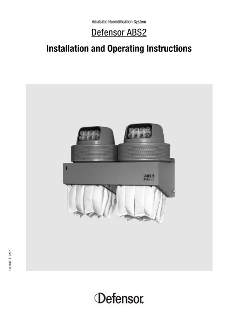
Adiabatic Humidification System<br />
<strong>Defensor</strong> <strong>ABS2</strong><br />
<strong>Installation</strong> <strong>and</strong> <strong>Operating</strong> <strong>Instructions</strong>
Contents<br />
1. Introduction 4<br />
1.1 Let’s get started! 4<br />
1.2 Important instructions! 4<br />
2. System overview 6<br />
3. Principle of operation 9<br />
4. <strong>Installation</strong> 10<br />
4.1 Appliance location 10<br />
4.2 Appliance installation 12<br />
4.3 Water connections 13<br />
4.4 Electrical <strong>Installation</strong> 15<br />
4.5 Configuration 17<br />
5. Commissioning, operation <strong>and</strong> shutdown 19<br />
5.1 Commissioning/operation 19<br />
5.2 Shutdown 19<br />
6. Maintenance 20<br />
6.1 Important notes on maintenance 20<br />
6.2 Dismantling procedures 21<br />
6.3 Cleaning works 23<br />
6.4 Humidifier reassembly 24<br />
7. What if … ? 26<br />
7.1 Malfunction 26<br />
7.2 Fault elimination 28<br />
8. Appliance specifications 29<br />
8.1 Technical data 29<br />
8.2 <strong>Operating</strong> conditions 29<br />
9. Spare parts list 30
1. Introduction<br />
1.1 Let’s get started!<br />
1.2 Important instructions!<br />
4<br />
Congratulations on your purchase of a <strong>Defensor</strong> <strong>ABS2</strong> adiabatic humidification<br />
system.<br />
You now own a powerful humidification system which meets the latest<br />
hygiene requirements <strong>and</strong> which offers outst<strong>and</strong>ing operating convenience.<br />
The special features of the <strong>ABS2</strong> are:<br />
– high humidification capacity<br />
– sturdy construction<br />
– modular design<br />
– low power consumption<br />
– simple operation <strong>and</strong> maintenance<br />
– simple installation without structural modifications<br />
Please read this installation <strong>and</strong> operating manual carefully <strong>and</strong> follow the<br />
instructions. This will do much to ensure the safe <strong>and</strong> dependable<br />
operation of your air humidifier.<br />
Delivery<br />
On delivery:<br />
– Check the appliance for shipping damage. Immediately report any<br />
damage to the forwarding company <strong>and</strong> to your <strong>Defensor</strong> dealer.<br />
– Check the delivery for completeness. Your <strong>Defensor</strong> dealer will immediately<br />
make up any incomplete shipments.<br />
Safety<br />
– This unit was shipped from the factory in a perfectly safe condition. To<br />
ensure its continued safety, please:<br />
– Follow all instructions <strong>and</strong> obey all warnings in this installation<br />
<strong>and</strong> operating manual.<br />
– Observe all local safety regulations governing work on mainspowered<br />
electrical <strong>and</strong> electronic appliances.<br />
– The air humidifier should be installed, serviced, maintained <strong>and</strong> repaired<br />
only by qualified persons familiar with the equipment.<br />
– Before carrying out any work on the <strong>Defensor</strong> <strong>ABS2</strong> set the unit out<br />
of operation, disconnect it from the power supply <strong>and</strong> secure the<br />
unit against unintentional power-up according the instructions<br />
given in chapter 5.2.<br />
– Setup, maintenance <strong>and</strong> repair of the electrical installation of the <strong>Defensor</strong><br />
<strong>ABS2</strong> must be carried out only by experts being aware of possible<br />
danger <strong>and</strong> implications.
– Poorly maintained humidifiers may endanger health. Therefore it is<br />
m<strong>and</strong>atory to observe the specified maintenance intervals <strong>and</strong> to<br />
carry out maintenance work in strict accordance with the instructions.<br />
– The humidifier must be operated only under the specified operating<br />
conditions (see section 8.2, “<strong>Operating</strong> conditions”).<br />
– Use only genuine accessories <strong>and</strong> spare parts available from your<br />
<strong>Defensor</strong> supplier.<br />
– The <strong>Defensor</strong> <strong>ABS2</strong> <strong>and</strong> the optional accessories must not be modified<br />
in any way without the written consent of Axair Ltd.<br />
<strong>Installation</strong> <strong>and</strong> operating manual<br />
– Keep this manual in a safe place where it will be immediately to h<strong>and</strong>.<br />
– If you lose the manual, contact your <strong>Defensor</strong> dealer to obtain an immediate<br />
replacement.<br />
Customer service<br />
Axair Ltd. has an extensive worldwide dealer network with skilled technicians<br />
offering prompt service at all times. Contact your <strong>Defensor</strong> dealer in<br />
the event of any malfunctions or if you have questions concerning air humidification.<br />
5
2. System overview<br />
6<br />
13<br />
12<br />
1a Motor housing<br />
1b Carrier frame<br />
2a Ring filter (Z92)<br />
2b Flat filter (Z93)<br />
3a Aerosol discharge hood <strong>and</strong> directing hood<br />
3b Discharge housing<br />
4a/b Fan, secondary air system<br />
5a/b Electric motor<br />
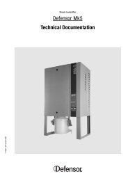
The <strong>ABS2</strong> adiabatic humidification system is of modular design. The <strong>ABS2</strong><br />
appliance basically consists of the following main components:<br />
– Atomizer unit<br />
– Base unit with integrated controller<br />
– Filter unit<br />
The AU35 <strong>and</strong> AU90 atomizer units<br />
The atomizer units are available in two different versions: AU35 <strong>and</strong><br />
AU90.<br />
They can be installed in all base units of the <strong>ABS2</strong>. Both atomizer units<br />
operate according to the same basic principle. However, they have<br />
different humidification capacities (AU35: 3.5 l/hr, AU90: 9.0 l/hr).<br />
The atomizer units consist of the following items:<br />
AU90 AU35<br />
10<br />
9<br />
8<br />
6<br />
3a<br />
4<br />
5<br />
2a<br />
1a<br />
11<br />
7<br />
13<br />
12<br />
5 4 2b<br />
10<br />
6 Impeller, primary air system<br />
7 Spinning disk<br />
8 Guide disk<br />
9 Distributor cone<br />
10 Suction tube<br />
11a/b Atomizer grid<br />
12 Insert<br />
13 Mains connection<br />
9<br />
8<br />
3b<br />
1b<br />
6 7<br />
11
1<br />
11<br />
12<br />
4<br />
5<br />
3a<br />
6<br />
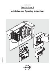
The SU11, SU21, DU11 <strong>and</strong> DU21 base units<br />
The base units are available in various versions. These are derived from<br />
two basic configurations:<br />
– SU11 <strong>and</strong> DU11: base unit with water-drain connection <strong>and</strong> automatic<br />
flushing system.<br />
– SU21 <strong>and</strong> DU21: base unit with automatic level security device, but<br />
without water-drain connection.<br />
Both basic configurations are available as single units (SU11/SU21) <strong>and</strong> as<br />
double units (DU11/DU21).<br />
The two basic configurations consist of the following items:<br />
SU11/DU11 SU21/DU21<br />
(with water-drain) (without water-drain)<br />
8<br />
1 Connection for pressurized water<br />
2 Water reservoir<br />
3a Inlet valve<br />
3b Inlet valves (2 pcs.)<br />
4 Lifting magnet of drain valve<br />
5 Drain valve<br />
6 Drain connection<br />
2<br />
10<br />
1<br />
11<br />
9<br />
8<br />
3b<br />
12<br />
6<br />
7<br />
7 Drain pipe<br />
8 Float switch<br />
9 Maximum level switch<br />
10 Microswitch for filter unit<br />
11 Mains connection, atomizer unit<br />
12 Cable gl<strong>and</strong>s<br />
2<br />
10<br />
7
8<br />
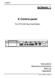
Filter units FU1, FU2 <strong>and</strong> FU3<br />
The air inlets of the primary <strong>and</strong> the secondary air systems are equipped<br />
with filter units to protect the internals of the humidifier from contamination.<br />
The following filter units are used:<br />
– Primary air system<br />
– FU1 flat filter for use in rooms with very small dust concentrations.<br />
– FU2 pocket filter for use in rooms with large dust <strong>and</strong> fibre concentrations.<br />
FU1 FU2<br />
– Secondary air system<br />
– FU3 ring filter for use in rooms with high dust <strong>and</strong> fibre concentrations<br />
(for the AU90 atomizer unit only).<br />
– Flat filter (st<strong>and</strong>ard configuration atomizer unit AU35).<br />
FU3
3. Principle of operation<br />
1<br />
The <strong>ABS2</strong> adiabatic humidification system operates according to the atomization<br />
principle.<br />
The water is drawn in through suction tube (1) from the reservoir <strong>and</strong> is<br />
hurled from impeller (2) <strong>and</strong> spinning disk (3) against atomizer grid (4),<br />
thereby producing an aerosol (fog).<br />
Impeller (2) draws in room air through the bottom of the base unit. This air<br />
then passes through a filter (FU1 or FU2) <strong>and</strong> forms the primary stream<br />
which transports the aerosol to the atomizer outlet.<br />
Fan (6) draws in ambient air through the top surface of the AU35 atomizer<br />
unit (or through the annular inlet of the AU90) <strong>and</strong> is also routed to the<br />
outlet. This secondary air stream takes up the aerosol <strong>and</strong> discharges it into<br />
the room. The separate air-guidance systems result in the uniform spatial<br />
distribution of the aerosol.<br />
2<br />
6<br />
FU1/FU2<br />
5<br />
3<br />
4<br />
The atomizer unit is powered by a maintenance-free electric motor (5)<br />
which is controlled by an external humidistat <strong>and</strong> the built-in controller.<br />
In both basic configurations of the base units, the water supply to the<br />
reservoir is controlled by the float switch <strong>and</strong> the inlet valve (SU11/DU11)<br />
or the two inlet valves (SU21/DU21), respectively.<br />
9
4. <strong>Installation</strong><br />
4.1 Appliance location<br />
10<br />
The <strong>ABS2</strong> appliances are extremely easy to install. Nevertheless all<br />
installation work should be carried out by suitably trained personnel.<br />
Locating the humidifier<br />
Please observe the following locating instructions to ensure the correct<br />
operation of the humidifier:<br />
– The <strong>ABS2</strong> humidifiers are designed for wall mounting. Make sure that<br />
the structure (wall, pillar, etc.) on which the appliance is to be mounted<br />
has sufficient carrying capacity <strong>and</strong> can accommodate the fastening<br />
elements.<br />
– Locate the appliances such that the aerosol stream can spread freely.<br />
The obstruction of the aerosol stream by objects such as tubular racks,<br />
machines, supports, etc., will result in stagnation <strong>and</strong> the formation of<br />
turbulence which could cause condensation. Since the atomizer units<br />
can be turned horizontally, the aerosol stream can be directed to bypass<br />
any obstructions.<br />
The dimensions (approximate values) for the spreading of the aerosol<br />
stream of the individual appliance configurations are tabulated below.<br />
The dimensions relate to a room temperature of 20°C <strong>and</strong> a relative<br />
humidity of 45%. The spread of the aerosol stream is reduced at higher<br />
temperatures <strong>and</strong>/or lower relative humidity <strong>and</strong> enlarged at lower<br />
temperatures <strong>and</strong>/or higher relative humidity.<br />
Appliance configuration<br />
Designation AU35+SU11/21 AU35+DU11/21 AU90+SU11/21 AU90+DU11/21<br />
Aerosol stream length “l” 5 – 6 m 5 – 6 m 6 – 8 m 6 – 8 m<br />
Aerosol stream width “b” 1.5 m 3 – 5 m 1.5 m 3 – 5 m<br />
b<br />
l<br />
top view<br />
Rotation angle “α”<br />
atomizer unit<br />
120° 60° 160° 100°<br />
α<br />
α<br />
α<br />
α<br />
SU11/21<br />
b<br />
α<br />
l<br />
α<br />
DU11/21
– Humid air rises because it is lighter than dry air. Therefore a minimum<br />
distance must be maintained between the ceiling of the room <strong>and</strong> the<br />
appliance. This prevents the aerosol stream from condensing on the<br />
ceiling.<br />
Note: If there are support elements (e.g. ceiling joists, roof beams) in the<br />
vicinity of the aerosol stream, the minimum distance applies to the bottom<br />
surface of the support element.<br />
Appliance configuration<br />
Designation AU35+SU11/21 AU35+DU11/21 AU90+SU11/21 AU90+DU11/21<br />
Minimum distance “a” between 0.6 m 0.8 m 1.0 m 1.2 m<br />
ceiling <strong>and</strong> top of humidifier<br />
min. 2.2 m a<br />
side view<br />
– Mount the appliance such that there is sufficient room for maintenance.<br />
Also make sure that the appliances are readily accessible <strong>and</strong> that there<br />
is no accident risk during maintenance.<br />
– If appliances are to be installed facing each other, make sure that they<br />
are at least 15 to 20 m apart.<br />
– Insulate cold water piping in the vicinity of the aerosol stream (risk of<br />
condensation).<br />
– The evaporation process extracts heat from the ambient air. Make sure,<br />
therefore, that the aerosol stream is not directed at persons.<br />
– The base unit must be level (longitudinally <strong>and</strong> transversely) to ensure<br />
correct operation.<br />
Locating the external humidistat<br />
To ensure correct control of the <strong>Defensor</strong> <strong>ABS2</strong> please observe the notes<br />
on appropriate location of your humidistat (e.g. <strong>Defensor</strong> H5 humidistat ).<br />
min. 2.2 m a<br />
11
4.2 Appliance installation<br />
12<br />
22<br />
344<br />
205<br />
280<br />
81 300 81<br />
304<br />
511<br />
54<br />
60<br />
20<br />
Safety instructions<br />
– Since the humidifiers are usually mounted at a considerable height,<br />
please observe the following safety instructions:<br />
– Whenever possible, use a firm platform when mounting an appliance.<br />
If a platform cannot be used, use a step ladder (Straight ladders are not<br />
permissible).<br />
– Obtain assistance for difficult operations.<br />
– Use barriers to safeguard the work zone.<br />
– Use only the fastening material supplied to attach the base unit . If, in<br />
your particular case, it is not possible to attach the unit with the supplied<br />
material, choose a fastening system of similar stability. Contact your<br />
<strong>Defensor</strong> dealer in cases of doubt.<br />
Mounting the humidifier<br />
• Mark the positions for the base-unit fastening holes on the wall (see<br />
figure below). Use a spirit level to check the alignment.<br />
283<br />
474<br />
32<br />
ø40<br />
22<br />
344<br />
133<br />
81 419 419<br />
81<br />
304<br />
205<br />
280<br />
511<br />
54<br />
60<br />
283<br />
32<br />
ø40<br />
20<br />
704<br />
133
4.3 Water connections<br />
• Drill the 12 mm diameter holes <strong>and</strong> insert the supplied screw anchors.<br />
• Screw in the screws until the heads are 8 mm away from the wall<br />
surface.<br />
• Hang the base unit on the screws <strong>and</strong> then tighten them completely. Use<br />
the spirit level again to check horizontal alignment.<br />
• Insert filter unit(s) (FU1 or FU2) from below in the retainers of the base<br />
unit. Swing the filter unit(s) upwards <strong>and</strong> fasten with retaining latches.<br />
Note: Since the filter units are square, their orientation is immaterial.<br />
• Install the insert from the base unit from above (observe orientation).<br />
• Carefully insert the atomizer unit into the base unit from above <strong>and</strong> turn<br />
it to the desired position.<br />
Important! Make sure that the electric cable of the atomizing unit is not<br />
pinched.<br />
• AU90: Mount the directing hood <strong>and</strong> then the aerosol discharge hood on<br />
the atomizer unit. Also mount the ring filter (if used).<br />
• Plug in the electric cable of the atomizer unit on the left side of the base<br />
unit.<br />
Water supply<br />
Use 6 mm ID/8 mm OD pressure piping for feeding the pressurized water.<br />
Connect piping to the pressurized-water connection on the base unit (outside<br />
thread G3/4" or G1/2"). To prevent the inlet valve(s) from soiling, it is<br />
m<strong>and</strong>atory to install a sieving filter valve (e.g. option Z261) in the water<br />
supply. Install the supplied strainer valve in the pressurized-water tubing in<br />
the vicinity of the appliance. This allows the interruption of the water supply<br />
without shutting off the main valve.<br />
Note: The reducing nipple (3/4" to 1/2") for direct connection of the optional<br />
strainer valve “Z261” to the appliance is included in the delivery<br />
schedule.<br />
Admissible water pressure range: 1…6 bar (no pressure peaks)<br />
Admissible water temperature: 3…35 °C<br />
Note: Observe the local regulations regarding water connections!<br />
G 3/4"<br />
G 1/2"<br />
Z261<br />
p= 1…6 bar<br />
T= 3…35 °C<br />
13
14<br />
inner Ø= 40mm<br />
min. inner Ø= 37mm<br />
10°<br />
l<br />
inner Ø= >40mm<br />
Water-quality information:<br />
– Use only fresh drinking water to supply the appliance. It is not permissible<br />
to supply the appliance with water from open water courses,<br />
because of the high germ count (microorganisms).<br />
– We recommend the use of a demineralization system, (e.g. a reverseosmosis<br />
system) when the water is very hard (mineral-rich).<br />
Caution! Fully demineralized water (VE water) from a reverseosmosis<br />
system is aggressive. In this case all lines <strong>and</strong> connectors of<br />
the water installation (supply <strong>and</strong> drain) must be made of stainless steel<br />
(minimum requirements according to DIN 1.4301) or plastic.<br />
Note: Base exchangers (water softeners) are not suitable for watertreatment<br />
purposes because they do not reduce the quantity of minerals<br />
dissolved in the water. Phosphate cartridges are also unsuitable because<br />
they increase the minerals dissolved in the water.<br />
– Do not add disinfectants to the water. These are discharged into the<br />
ambient air during the atomization process <strong>and</strong> may cause mucousmembrane<br />
irritation or allergies.<br />
Please consult your <strong>Defensor</strong> dealer if you have questions concerning<br />
water treatment.<br />
Water drain line<br />
Basic units SU11 <strong>and</strong> DU11 with automatic flushing<br />
Via a siphon trap, connect the drain of the basic unit (inner Ø= 40mm)<br />
to a drain line of the building (inner Ø >40mm). Use rigid plastic pipe<br />
(min. inner Ø= 37mm) for the connection <strong>and</strong> route the pipe with a<br />
downward pitch of at least 10°. To ensure that the entire reservoir<br />
content can be discharged when the appliance is emptied, the connecting<br />
pipe should not be shorter than:<br />
– for the SU11 base unit: about 1m – for DU11 base unit: about 2m Use a hose clip on the drain connection to fasten the installed line.<br />
Notes:<br />
– It is advisable to use steel piping (min. requirements according to<br />
DIN 1.4301 if VE-water is used) for the drain line in exposed locations.<br />
– For safety reasons, do not use flexible tubing for the drain line.<br />
Base units SU21 <strong>and</strong> DU21 with automatic level security device<br />
The drain connections on base units SU21 <strong>and</strong> DU21 are closed with a<br />
drain pipe with a threaded cap. The drain cap is not installed when the<br />
appliance is delivered. To install the drain pipe, proceed as follows:<br />
• Insert the drain pipe into the drain connection until it comes to a stop,<br />
then secure it with the hose clip.
4.4 Electrical <strong>Installation</strong><br />
100…115 VAC<br />
220…240VAC<br />
F Q<br />
(max.16 AT)<br />
L1<br />
N<br />
PE<br />
B1<br />
J2<br />
P<br />
N<br />
L1<br />
N<br />
N<br />
L1<br />
P<br />
N<br />
X3<br />
X1<br />
X2<br />
100V= 630 mAT<br />
230V= 315 mAT<br />
All work concerning the electrical installation must be performed only<br />
by adequately qualified personnel (electrician or workman with equivalent<br />
training).<br />
Please observe all local regulations concerning the electrical installation.<br />
Wiring diagram <strong>ABS2</strong><br />
A Control PCB (unit 1 up to unit 10, max.)<br />
B1 Humidistat (internal power supply)<br />
F External pre-fuse (max. 16 A, slow-blow)<br />
F1 Atomizer fuse: 220…240V= 6.3 A, slow-blow/250V<br />
100…115V= 16 A slow-blow/250V<br />
F2 Primary fuse: 220…240V= 630 mA, slow-blow/250V<br />
100…115V= 315 mA, slow-blow/250V<br />
F3 Secondary fuse: 1.6 A, slow-blow/250V<br />
H1 Red error indicator on base unit<br />
H2 External error indicator<br />
J1 Jumper (for SU11/DU11 units)<br />
J2 Jumper (power supply to humidistat)<br />
M1 Power supply of humidistat fan (option)<br />
S1 Float switch<br />
115<br />
230<br />
F2<br />
SW3<br />
F1<br />
F3<br />
(1.6 AT)<br />
NPL1<br />
X2<br />
L1<br />
N<br />
NPL1<br />
X2<br />
A<br />
Unit 2 X1<br />
N<br />
Q<br />
F<br />
(max.16 AT)<br />
A<br />
Unit 3 X1<br />
100V= 16 AT<br />
230V= 6.3 AT<br />
L1<br />
N<br />
N<br />
SW1<br />
OFF ON<br />
SW2<br />
DRAIN 1/2H 1<br />
FREEZE 1H 2<br />
FLUSH 2H 3<br />
RESERVE 4H 4<br />
1<br />
2 3 4<br />
X15<br />
+<br />
+24V<br />
(max. 50mA)<br />
Q<br />
1<br />
F (max.16 AT)<br />
Unit 1<br />
2 3 4<br />
– + –<br />
+24V<br />
M<br />
H2 M1<br />
A<br />
5 6<br />
X14 X13<br />
X12 X11 X10<br />
+24V<br />
Y1<br />
+24V<br />
+24V<br />
J1<br />
Y2<br />
Y3<br />
S1<br />
S2 Microswitch of filter unit<br />
S3 Maximum level switch<br />
(SU21/DU21 units only)<br />
SW1 <strong>Operating</strong> mode selector<br />
SW2 Flushing interval selector<br />
SW3 Voltage selector<br />
Q External mains or service switch<br />
X1 Power supply terminal<br />
X2 Terminal for humidistat<br />
X3 Terminal for atomizer unit<br />
Y1 Inlet valve<br />
Y2 Flushing valve (SU11/DU11 units only)<br />
Y3 2nd inlet valve (SU21/DU21 units only)<br />
S2<br />
H1<br />
S3<br />
15
16<br />
The control PCB holding the screw terminals <strong>and</strong> the DIP switches for<br />
configuration is located under the cover (fixed with 4 screws), on the left<br />
side of the base unit.<br />
Lead all connection cables through the cable gl<strong>and</strong>s (strain relief) to<br />
the control PCB. Important! Thoroughly tighten the cable gl<strong>and</strong>s to prevent<br />
humidity from entering the controller housing.<br />
Power supply<br />
Establish the power supply according to the wiring diagram while observing<br />
the following information:<br />
– The 2-pole service switch Q (located close to the base unit) <strong>and</strong> the<br />
fuse F (max. 10 A, slow-blow) are m<strong>and</strong>atory.<br />
– Minimum cable section: 3 x 1.5 mm2 – Caution! The appliances must be connected only to a mains with a<br />
protective earth. Do not override the protective effect by using an<br />
extension cable without an earth conductor.<br />
Any discontinuity in the earth conductor inside or outside the appliance<br />
or undoing the earth-conductor connection can render the appliance<br />
dangerous. The deliberate disconnection of the earth conductor is<br />
prohibited!<br />
– Caution! Make sure the selected supply voltage (see setting of switch<br />
“SW3” on control PCB) matches the local mains voltage. If this is not the<br />
case adjust switch “SW3” accordingly.<br />
Connection of an external humidistat<br />
Connect the external humidistat to screw terminal X2 (internal power<br />
supply) according to the wiring diagram.<br />
Danger! Mains voltage (up to 230V) is applied to connector L1 of screw<br />
terminal X2. Therefore, disconnect the unit from the mains (maintenance<br />
switch to off) before carrying out installation work.<br />
Note: Particular applications may require the humidistat to be powered<br />
externally. In this case ask your <strong>Defensor</strong> dealer for the special wiring<br />
diagram.<br />
Connection of an external error indicator<br />
Connect the external error indicator (24 VDC) to connectors 1 <strong>and</strong> 2 of<br />
screw terminal X15 according to the wiring diagram. The maximum<br />
admissible current is 50 mA.<br />
Supplying power to the fan of the humidistat <strong>Defensor</strong> H5-V<br />
The power supply to the fan of the humidistat <strong>Defensor</strong> H5-V is made<br />
via connectors 3 <strong>and</strong> 4 of screw terminal X15 (see wiring diagram).<br />
To conclude setup work connect the grounding wire to the cover, then fix<br />
the cover with the 4 Phillips screws.
4.5 Configuration<br />
Configuration of the <strong>ABS2</strong> is done via switches SW1 (operating mode<br />
selector), SW2 (flushing interval selector) <strong>and</strong> SW3 (voltage selector) of<br />
the control PCB.<br />
Danger, lethal voltage! Before starting configuration work, set the<br />
<strong>Defensor</strong> <strong>ABS2</strong> out of operation <strong>and</strong> disconnect the unit from the<br />
mains according to chapter 5.2.<br />
Loosen the 4 screws of the cover on the left side of the base unit. Carefully<br />
lift off the cover, then remove the grounding wire from the cover.<br />
Setting the operating mode (SW1)<br />
Switch OFF ON<br />
1<br />
(Drain)<br />
2<br />
(Freeze)<br />
3<br />
(Flush)<br />
SW3<br />
Setting for appliances including base unit<br />
without drain valve (SU21 <strong>and</strong> DU21).<br />
Antifreeze disabled.<br />
SW1<br />
Note: This switch has no function on base units SU21/DU21!<br />
Periodic flushing during humidification disabled.<br />
Note: This switch has no function on base units SU21/DU21!<br />
4 reserved<br />
off on<br />
1<br />
2<br />
3<br />
4<br />
SW2<br />
Setting for appliances including base unit with<br />
drain valve (SU11 <strong>and</strong> DU11).<br />
Antifreeze enabled, required when operating<br />
the <strong>ABS2</strong> at temperatures around the freezing<br />
point (e.g. in cold-storage depots).<br />
Periodic flushing during humidification enabled.<br />
17
18<br />
Setting the flushing interval (SW2) (SU11/DU11 only)<br />
The flushing interval is the period between two flushing cycles. A timer built<br />
into the controller logs the time (based on the hours of operation of the<br />
atomizer). A flushing cycle is initiated each time the specified interval has<br />
elapsed.<br />
The time between two flushing cycles can be defined as 30, 60, 120 or 240<br />
minutes. The time to be set depends on the prevailing operating conditions<br />
(dustiness, water quality).<br />
Recommendation: – Very dusty conditions <strong>and</strong>/or hard water:<br />
Flushing interval 30 minutes<br />
– Normal dustiness <strong>and</strong>/or medium-hardness water:<br />
Flushing interval 60 - 120 minutes<br />
– Slight dustiness <strong>and</strong>/or demineralized water:<br />
Flushing interval 120 - 240 minutes<br />
Setting of switch SW2 Flushing interval in minutes<br />
1 30<br />
2 60<br />
3 120<br />
4 240<br />
Selection of the supply voltage (SW3)<br />
The <strong>ABS2</strong> supports two different voltage ranges. Selection of the appropriate<br />
supply voltage is done via switch SW3.<br />
Setting of switch SW3 Supply voltage<br />
115 100…115 VAC/50…60 Hz<br />
230 220…240 VAC/50…60 Hz<br />
To conclude setup work connect the grounding wire to the cover, then fix<br />
the cover with the 4 Phillips screws.
5. Commissioning, operation <strong>and</strong> shutdown<br />
5.1 Commissioning/operation<br />
5.2 Shutdown<br />
Proceed as follows to ready the humidifier for operation:<br />
It is assumed that the unit has already been installed, connected <strong>and</strong><br />
configured according to the instructions (see chapter 4).<br />
• Turn on the water supply.<br />
Attention! Appliances with base unit SU21 or DU21; check whether the<br />
drain neck is closed properly.<br />
• On the external humidistat set the reference humidity to the desired<br />
value.<br />
• Actuate the maintenance switch.<br />
Appliances with base unit SU11 or DU11: the water reservoir is flushed<br />
<strong>and</strong> then filled up to the working level.<br />
Appliances with base unit SU21 or DU21: the water reservoir is filled up<br />
to the working level.<br />
The humidifier is now in the ready mode. The atomizer will be activated only<br />
if the air humidity is lower than the set reference value. On base units SU11/<br />
DU11 the flushing of the water reservoir always takes place according to<br />
the preset flushing interval, even in st<strong>and</strong>by mode (see section “Setting the<br />
flushing interval” in chapter 4.5).<br />
If malfunction occurs during operation, the red error indicator on the<br />
front panel of the base unit starts flashing or lights up constantly (for<br />
additional information refer to chapter 7).<br />
Proceed as follows to put the humidifier out of operation:<br />
• Disconnect the humidifier from the mains (set the maintenance<br />
switch to off) <strong>and</strong> secure the system against unintentional start-up.<br />
Danger, lethal voltage! If the humidistat controlling your unit is fed<br />
by an external power supply, the external voltage is applied to<br />
the control PCB. In this case you must disconnect the humidistat<br />
from power supply.<br />
The water reservoir of appliances equipped with base unit SU11 or<br />
DU11 is drained <strong>and</strong> flushed automatically at shutdown time.<br />
The water reservoir of appliances with base unit SU21 or DU21 should<br />
be drained manually via the drain neck if the humidifier is to be set out<br />
of operation for an extended period (hygiene).<br />
• Turn off water supply (close sieving filter valve).<br />
19
6. Maintenance<br />
6.1 Important notes on maintenance<br />
20<br />
Dust pollution level Periodic<br />
cleaning<br />
high, e.g.<br />
textile mills, print shops<br />
<strong>and</strong> paper industry,<br />
wood processing<br />
medium, e.g.<br />
storage facilities of<br />
the food industry<br />
low, e.g.<br />
cold rooms
Water Hardness Maintenance<br />
quality level intervals<br />
hard >18° d 2 - 4 weeks<br />
normal 8 - 18° d 4 - 8 weeks<br />
soft (VE) 0 - 8° d 8 weeks<br />
6.2 Dismantling procedures<br />
– Complete maintenance of the humidifier<br />
Depending on the appliance configuration, a complete maintenance<br />
intervention takes from 3/4 h (single unit) to 1 1/4 h (double unit).<br />
Maintenance frequency depends on the operating conditions (see<br />
opposite table). In addition to the parts listed in section “Periodic<br />
cleaning”, the following items require thorough cleaning:<br />
– Discharge assembly, discharge hood/housing<br />
Note: Dismantling procedures <strong>and</strong> cleaning of individual components required<br />
on the occasion of periodic servicing or overall maintenance are described<br />
in chapters 6.2 <strong>and</strong> 6.3.<br />
Safety precautions<br />
– Danger, lethal voltage! Before you start cleaning, set the <strong>Defensor</strong><br />
<strong>ABS2</strong> out of operation <strong>and</strong> disconnect the unit from the mains<br />
according to chapter 5.2.<br />
– Make sure that those around you know that you are working on the<br />
appliance.<br />
– Since the humidifiers are usually mounted at a considerable height,<br />
please observe the following safety instructions: Whenever possible,<br />
use a firm platform when maintaining an appliance. If a platform cannot<br />
be used, use a step ladder (Straight ladders are not permissible).<br />
Putting the system out of operation<br />
Put the humidifier out of operation according to chapter 5.2.<br />
Filter unit removal (FU1/FU2)<br />
• Turn the retainer latch of the filter unit on the bottom of the base unit to<br />
the side. Remove the filter unit (base units SU11/SU21) or the two filter<br />
units (base units DU11/DU21) in a downward direction.<br />
Note: Protect the inside face of the filter against contamination by laying<br />
the filter unit with the inside surface facing downwards.<br />
Water reservoir removal<br />
• DU11/DU21: Turn the retaining latches of the connecting bar to the side.<br />
Remove the connecting bar.<br />
• SU21/DU21: Undo the flexible tubing clip on the drain tubing.<br />
• Pull the drain tubing on the water reservoir downwards <strong>and</strong> remove<br />
sideways from the connection on the water reservoir.<br />
• Turn the retaining latches of the water reservoir to the side <strong>and</strong> pull the<br />
water reservoir out from below.<br />
21
22<br />
12<br />
11a<br />
Atomizer unit removal<br />
• Unplug the electric cable(s) between the atomizer unit(s) <strong>and</strong> the base<br />
unit.<br />
• AU90: Lift off the aerosol discharge hood <strong>and</strong> then the directing hood<br />
(11a). Remove the ring filter unit (12, if installed).<br />
AU35: Undo the two catches <strong>and</strong> lift off the discharge housing together<br />
with the flat filter (11b).<br />
• Carefully lift the atomizer unit (10) on the carrier frame (1a/1b) up <strong>and</strong><br />
out of the base unit.<br />
• Place the atomizer unit (10) together with the fan wheel downwards onto<br />
the carrier frame. Make sure that the unit does not st<strong>and</strong> on the fan<br />
wheel (use wooden blocks).<br />
• Hold the disks (9) (guide disk (2), distributor cone (3), 3 spinning disks<br />
(4) <strong>and</strong> impeller (5)) firmly <strong>and</strong> undo the suction tube (6) in an anticlockwise<br />
direction.<br />
• Remove the disks (9) from the drive shaft. Press the impeller <strong>and</strong> spinning<br />
disks away from the distributor cone by h<strong>and</strong>. Then, remove the<br />
distributor cone from the guide disk.<br />
• Pull the catch springs outwards <strong>and</strong> carefully withdraw the atomizer<br />
grid (7) from the centring device.<br />
• Remove the insert (8) from the base unit.<br />
1a<br />
2<br />
3<br />
4<br />
5<br />
6<br />
7<br />
8<br />
9<br />
10<br />
1b<br />
2<br />
3<br />
4<br />
5<br />
6<br />
7<br />
8<br />
9<br />
10<br />
11b
6.3 Cleaning works<br />
Cleaning the water system<br />
Wash the water reservoir, insert, atomizer grid, suction tube, <strong>and</strong> the disks<br />
using a lukewarm soap solution <strong>and</strong> then rinse them thoroughly with water.<br />
If the components are heavily encrusted with chalk, soak them in 8 % formic<br />
acid until the lime layer is dissolved. Finally, treat the components as<br />
described above.<br />
During the cleaning operation make sure that:<br />
– the external edges of the disks are not damaged. Disks damage<br />
reduces the efficiency of the humidifier <strong>and</strong> can cause bearing damage<br />
(unbalance).<br />
– the vanes of the atomizer grid are not bent. Bent vanes adversely affect<br />
the atomization process.<br />
– the drain opening of the insert is open so that the return water can flow<br />
back into the water reservoir.<br />
– the inlet of the water suction connection is open so that the water<br />
throughput is ensured.<br />
Use a cloth moistened with soap solution or a sponge to wash the components<br />
inside the base unit <strong>and</strong> the remaining components of the atomizing<br />
unit. Then rub the components with a wet cloth (clean water) several times.<br />
If the components are heavily encrusted with chalk, rub them with an acidsoaked<br />
cloth (8 % formic acid). Allow the acid to act for some time <strong>and</strong> then<br />
wash the components.<br />
Caution! Make sure that no cleaning agents (water, soap solution, acid,<br />
etc.) get into the electric motor during cleaning.<br />
The strainer valve (13) must be inspected during every service intervention<br />
<strong>and</strong> cleaned if necessary.<br />
Cleaning-agent notes:<br />
– Formic acid is available at all pharmacies.<br />
Caution! Formic acid attacks the skin as well as the mucous membranes.<br />
Therefore protect your skin, the eyes <strong>and</strong> the respiratory tract<br />
from contact with the acid or its fumes. (Wear gloves, safety goggles <strong>and</strong><br />
work in a well-ventilated room or outdoors).<br />
– The use of disinfectants is allowed only when they leave no toxic<br />
residues. In any case the components must be thoroughly rinsed with<br />
water after cleaning.<br />
– Caution! Do not use solvents or other aggressive substances for<br />
cleaning.<br />
– Do not use scouring equipment (wire brushes, scouring cloths, etc.)<br />
for cleaning. Scratches in the surfaces of the components encourage<br />
the growth of microorganisms.<br />
23
6.4 Humidifier reassembly<br />
24<br />
Cleaning the air system<br />
Filter units<br />
– If the filter units are only lightly contaminated: clean the outside<br />
surface of the filter units with a vacuum cleaner.<br />
– If the filter units are heavily contaminated: replace them.<br />
Important notes:<br />
– Apply the vacuum cleaner only to the outside surface of the filter units<br />
so that the contaminatory matter does not penetrate deeper into the<br />
filter fabric <strong>and</strong> reduce the efficiency of the filter.<br />
– The filter units must not be used for more than 1 year. Under severe<br />
operating conditions, the maximum service time must be reduced<br />
accordingly.<br />
– Install only absolutely dry filters. Damp filters promote the growth of<br />
microorganisms.<br />
Discharge housing / aerosol discharge hood <strong>and</strong> directing hood<br />
Wash all components with a lukewarm soap solution <strong>and</strong> then rinse<br />
thoroughly with water.<br />
Note: observe the instructions regarding cleaning agents in the “Cleaning<br />
the water system” section.<br />
Before starting with the reassembly, check all components for operational<br />
integrity <strong>and</strong> any defects. Pay special attention to the float switches <strong>and</strong> the<br />
drain valve (SU11 <strong>and</strong> DU11 only). Replace defective components.<br />
Reservoir installation<br />
• Insert the reservoir on the drain connection side into the retainer of the<br />
base unit, swing upwards <strong>and</strong> secure with the retaining latches.<br />
• Push the drain tubing onto the connection on the reservoir.<br />
• Caution! In the case of the SU21/DU21 base units, secure the drain<br />
tubing with a hose clip <strong>and</strong> close the drain tube with the threaded<br />
cap.<br />
Filter unit installation<br />
• Insert filter unit(s) (FU1 or FU2) from underneath into the retainers of the<br />
base unit. Swing up <strong>and</strong> secure with the retaining latches.<br />
Note: The filter units are square <strong>and</strong> their orientation is immaterial.
Atomizer unit installation<br />
• Carefully push the atomizer grid onto the centring device until the<br />
latching springs engage.<br />
• Mount the disk unit: slip the distributor cone onto the guide disk, then<br />
mount the spinning disks <strong>and</strong> the impeller to the distributor cone.<br />
• Grease the drive shaft <strong>and</strong> thread (use silicone or water-pump grease).<br />
Now mount the disk unit on the drive shaft (Note! Observe position of<br />
drive studs).<br />
• Hold the disks firmly <strong>and</strong> screw the suction tube clockwise on the drive<br />
shaft <strong>and</strong> tighten by h<strong>and</strong>.<br />
• Install the insert in the base unit from above.<br />
• Carefully guide the atomizer unit into the base unit from above <strong>and</strong> turn<br />
it into the desired position.<br />
Caution! Make sure that the electric cable of the atomizer unit does not<br />
become pinched.<br />
• AU35: Mount the discharge housing together with the flat filter on the<br />
atomizer unit, <strong>and</strong> secure to the carrier frame with the two snap catches.<br />
AU90: Mount the directing hood on the atomizer unit followed by the<br />
aerosol discharge hood. Mount the ring filter unit (if installed).<br />
• Plug the electric cable(s) of the atomizer unit(s) into the connector(s) on<br />
the left side of the base unit.<br />
Starting<br />
Start the appliance as described in section 5.2.<br />
25
7. What if … ?<br />
7.1 Malfunction<br />
26<br />
The following table presents a selection of faults that may occur during<br />
operation of the humidifier, together with notes on their cause <strong>and</strong> appropriate<br />
remedies.<br />
Malfunction Cause Remedy<br />
The atomizer does not work<br />
<strong>and</strong> the red fault indicator<br />
flashes.<br />
The atomizer does not work<br />
<strong>and</strong> the red fault indicator<br />
lights up permanently.<br />
A puddle of water forms on the<br />
base unit after switching on.<br />
Microswitch of the filter unit has<br />
been triggered:<br />
– Filter unit(s) FU1 or FU2 are<br />
either missing or located<br />
incorrectly.<br />
– Microswitch defective.<br />
Level in the water reservoir too<br />
high or water reservoir is empty:<br />
– Water supply turned off or<br />
blocked.<br />
– Water inlet valve not electrically<br />
connected or defective.<br />
– SU11/DU11: Drain valve not<br />
tight, not electrically connected<br />
or defective.<br />
– Float switch jammed or heavily<br />
encrusted with chalk.<br />
Level in the water reservoir too<br />
high, maximum level switch<br />
triggered:<br />
– Float switch jammed or encrusted<br />
with chalk.<br />
– SU11/DU11: jumper J1 not<br />
installed (see provided wiring<br />
diagram).<br />
– Violent water movements in the<br />
reservoir due to air in the<br />
supply line.<br />
The electric cable is pinched under<br />
the atomizer unit.<br />
The atomizer does not run. Maintenance switch is set to “Off”.<br />
Primary fuse F2 or secondary fuse<br />
F3 on control PCB of the base unit<br />
defective.<br />
– Mount the filter unit(s) appropriately.<br />
– Check microswitch, replace, as<br />
required.<br />
– Check water supply line <strong>and</strong><br />
the strainer valve.<br />
– Check the water inlet valve.<br />
Replace if necessary.<br />
– Check drain valve. Clean or<br />
replace if necessary.<br />
– Check float switch. Clean or replace<br />
if necessary.<br />
– Check float switch. Clean or replace<br />
if necessary.<br />
– Install jumper J1 (see wiring<br />
diagram).<br />
– Note: This can occur only during<br />
initial operation or after draining<br />
the water line.<br />
Note: after having eliminated the<br />
problem, disconnect the unit from<br />
the mains for at least 10 seconds<br />
to reset the fault indicator.<br />
Remove the pinched cable.<br />
Set maintenance switch to “On”.<br />
Replace primary fuse F2 or secondary<br />
fuse F3 (according to the description<br />
given in chapter 7.2).
Malfunction Cause Remedy<br />
The atomizer keeps running<br />
<strong>and</strong> cannot be switched off by<br />
reducing the reference humidity<br />
value.<br />
The humidistat does not switch.<br />
The atomizer does not run.<br />
The humidistat activates the atomizer,<br />
but the atomizer does<br />
not start.<br />
The set reference humidity value<br />
is not reached. The atomizer runs<br />
continuously.<br />
The atomizer runs noisily (motor<br />
noise audible).<br />
Air humidity very low (95 % rh).<br />
Humidistat defective.<br />
Humidistat incorrectly set.<br />
Atomizer fuse F1 in base-unit terminal<br />
box is defective.<br />
The mains connection to the particular<br />
humidifier is interrupted.<br />
The electric cable of the atomizer<br />
unit is not connected.<br />
The thermostatic switch of the electric<br />
motor has tripped (motor is overheated).<br />
Air filters heavily contaminated.<br />
Room too large.<br />
Suction tube of atomizer unit<br />
blocked.<br />
Suction tube not installed.<br />
Disks not correctly installed.<br />
Suction tube has become undone.<br />
None.<br />
Check humidistat. Replace if necessary.<br />
None.<br />
Check humidistat. Replace if necessary.<br />
Set humidistat to the correct reference<br />
humidity value.<br />
Replace atomizer fuse F1.<br />
Check the wiring.<br />
Plug the atomizer-unit cable into<br />
the base unit<br />
Check the atomizing head (The<br />
motor shaft must rotate freely).<br />
Clean if necessary. Contact <strong>Defensor</strong><br />
dealer if necessary<br />
Clean air filters.<br />
Contact <strong>Defensor</strong> dealer.<br />
Check suction tube. Clean if necessary.<br />
Install suction tube.<br />
Check disks. Mount them correctly.<br />
Tighten suction tube.<br />
27
7.2 Fault elimination<br />
28<br />
Notes regarding fault elimination<br />
– Before eliminating faults, the <strong>Defensor</strong> <strong>ABS2</strong> must be taken out of<br />
operation according chapter 5.2.<br />
Danger! Make sure the mains supply to the humidifier is disconnected<br />
(check with voltage tester) <strong>and</strong> the stop cock of the water supply is<br />
closed.<br />
– Have faults eliminated by adequately qualified <strong>and</strong> trained personnel<br />
only (e.g. by a service engineer of your <strong>Defensor</strong> supplier).<br />
Malfunctions caused by the electrical installation must be repaired by<br />
authorized personnel only.<br />
Replacement of the fuses<br />
Caution! The electronic components on the control PCB are very susceptible<br />
to electrostatic discharge. When carrying out repairs to the control unit,<br />
appropriate measures (ESD-protection) must be taken to prevent damage<br />
to electronic components.<br />
Danger, lethal voltage! Before replacing defective fuses, set the<br />
<strong>Defensor</strong> <strong>ABS2</strong> out of operation <strong>and</strong> disconnect the unit from the<br />
mains according to chapter 5.2.<br />
• Loosen the 4 screws of the cover on the left side of the base unit.<br />
Carefully lift off the cover, then remove the grounding wire from the<br />
cover.<br />
F2<br />
F1<br />
F3<br />
• Replace fuses F1, F2 <strong>and</strong> F3 of the control PCB only with fuses<br />
matching the specifications below:<br />
– Atomizer fuse F1:<br />
Supply voltage 220…240V: 6.3 A, slow-blow/nom. voltage 250V<br />
Supply voltage 100…115V: 16 A, slow-blow/nom. voltage 250V<br />
– Primary fuse F2:<br />
Supply voltage 220…240V: 315 mA, slow-blow/nom. voltage 250V<br />
Supply voltage 100…115V: 630 mA, slow-blow/nom. voltage 250V<br />
– Secondary fuse F3: 1.6 A, slow-blow/nom. voltage 250V<br />
Caution! Never use refurbished fuses. Do not bridge the fuse holder.<br />
• Following replacement of the fuse(s) connect the grounding wire to the<br />
cover, then fasten the cover with the 4 Phillips screws.
8. Appliance specifications<br />
8.1 Technical data<br />
Appliance configuration<br />
Designation AU35+SU11/21 AU90+SU11/21 AU35+DU11/21 AU90+DU11/21<br />
Humidification capacity 3.5 l/h 9 l/h 7 l/h 18 l/h<br />
Air circulation 300 m3 /h 800 m3 /h 600 m3 /h 1600 m3 /h<br />
Power consumption 200 W 290 W 400 W 580 W<br />
Supply voltage 100…115VAC/50…60Hz or 220…240VAC / 50…60Hz<br />
Atomizer fuse F1 100…115V= 16A, slow-blow/250V or 220…240V= 6.3A, slow-blow/250V<br />
Primary fuse F2 100…115V= 630mA, slow-blow/250V or 220…240V= 315mA, slow-blow/250V<br />
Secondary fuse F3 1.6 A, slow-blow/250V<br />
Dimensions in mm (W x H x D) 462 x 474 x 511 462 x 704 x 511 1000 x 474 x 511 1000 x 704 x 511<br />
Weight (dry) 25.4 kg 27.5 kg 45.8 kg 50 kg<br />
Water content<br />
Water consumption<br />
1 l 1 l 2 l 2 l<br />
– without drain max. 3.5 l/hr max. 9.0 l/hr max. 7.0 l/hr max. 18.0 l/hr<br />
– Flushing cycle 30 min. max. 7.5 l/h max. 13.0 l/h max. 15.0 l/hr max. 26.0 l/hr<br />
– Flushing cycle 60 min. max. 5.5 l/hr max. 11.0 l/hr max. 11.0 l/hr max. 22.0 l/hr<br />
– Flushing cycle 120 min. max. 4.5 l/hr max. 10.0 l/hr max. 9.0 l/hr max. 20.0 l/hr<br />
– Flushing cycle 240 min. max. 4.0 l/hr max. 9.5 l/hr max. 8.0 l/hr max. 19.0 l/hr<br />
Feed-water pressure 100 - 600 kPa (1.0 - 6.0 bar)<br />
Pressurized water connection 8 mm OD/6 mm ID tubing, connection 3/4" or 1/2" (outside thread)<br />
Water drain connection Inner Ø 40 mm<br />
Drive Maintenance-free electric motor with thermostatic switch<br />
Control External humidistat (e.g. <strong>Defensor</strong> H5)<br />
Test <strong>and</strong> conformity certificates SEV, CE<br />
8.2 <strong>Operating</strong> conditions<br />
Temperature range: 2 - 40 °C<br />
Note: Contact your <strong>Defensor</strong> dealer if lower temperatures<br />
are involved.<br />
Humidity range: 0 - 98 % rh<br />
Water quality: Tap water<br />
Water demineralization is recommended if the mineral<br />
salt content of the water is high (>15 dH°, >27 fH°).<br />
Air: If the air is very dirty, it is advisable to use the pocketfilter<br />
unit FU2 in the primary air system <strong>and</strong> the ringfilter<br />
FU3 (AU90 only) in the secondary air system.<br />
Note: See section 4.1 “Appliance location” for additional information.<br />
29
9. Spare parts list<br />
30<br />
106<br />
107<br />
AU90<br />
104<br />
101<br />
102<br />
103<br />
105
Item Part no. Part designation<br />
101 1102094 Spare filter for FU3<br />
102 1104088 Fan<br />
103 1103920 Capacitor for supply voltage 220…240V<br />
1103924 Capacitor for supply voltage 100…115V<br />
104 1104143 Motor 220V/60Hz<br />
1104145 Motor 220…240V/50Hz<br />
1104149 Motor 100…115V/60Hz<br />
1104154 Motor 100…115V/50Hz<br />
105 1104085 Atomizer grid<br />
106 1104138 Turbine cpl.<br />
107 1110550 Insert<br />
31
32<br />
201<br />
206<br />
207<br />
203<br />
AU35<br />
202<br />
204<br />
205
Item Part no. Part designation<br />
201 1102369 Spare filter AU35<br />
202 1103941 Fan<br />
203 1103913 Capacitor for all supply voltages (2 pcs. for supply voltage 100…115V)<br />
204 1104348 Motor 220…240V/50Hz<br />
1109190 Motor 220V/60Hz<br />
1104353 Motor 100…115V/60Hz<br />
1104356 Motor 100…115V/50Hz<br />
205 1104517 Atomizer grid<br />
206 1104138 Turbine cpl.<br />
207 1110550 Insert<br />
33
34<br />
308<br />
307<br />
309<br />
301<br />
303<br />
306<br />
305<br />
SU11<br />
311<br />
310 312<br />
314<br />
302<br />
304<br />
313
Item Part no. Part designation<br />
301 1100816 Spare filter for FU1<br />
302 1101904 Spare filter for FU2<br />
303 1103934 Water reservoir<br />
304 1103927 Set of plugs<br />
305 1104103 Inlet valve<br />
306 1104107 Microswitch of filter unit<br />
307 1104112 Error indicator red<br />
308 1104122 Set of fuses (220…240VAC)<br />
1104127 Set of fuses (100…115VAC)<br />
309 1112403 Control PCB<br />
310 1104119 Sealing plates<br />
311 1104116 Socket complete<br />
312 1104091 Lifting magnet<br />
313 1104099 Float switch<br />
314 1104095 Drain connection<br />
35
36<br />
408<br />
407<br />
409<br />
401<br />
410<br />
406<br />
403<br />
411<br />
405<br />
415<br />
SU21<br />
402<br />
414<br />
412<br />
413
Item Part no. Part designation<br />
401 1100816 Spare filter for FU1<br />
402 1101904 Spare filter for FU2<br />
403 1103934 Water reservoir<br />
405 1104103 Inlet valve<br />
406 1104107 Microswitch of filter unit<br />
407 1104112 Error indicator red<br />
408 1104122 Set of fuses (220…240VAC)<br />
1104127 Set of fuses (100…115VAC)<br />
409 1112403 Control PCB<br />
410 1104119 Sealing plates<br />
411 1104116 Socket complete<br />
412 1104129 Maximum level switch<br />
413 1104099 Float switch<br />
414 1104095 Drain connection<br />
415 1104485 Drain pipe<br />
37
38<br />
508<br />
507<br />
501<br />
509<br />
514<br />
506<br />
504<br />
DU11<br />
511<br />
510 512<br />
502<br />
503<br />
505<br />
513
Item Part no. Part designation<br />
501 1100816 Spare filter for FU1<br />
502 1101904 Spare filter for FU2<br />
503 1103938 Water reservoir<br />
504 1103927 Set of plugs<br />
505 1104133 Inlet valve<br />
506 1104107 Microswitch of filter unit<br />
507 1104112 Error indicator red<br />
508 1104122 Set of fuses (220…240VAC)<br />
1104127 Set of fuses (100…115VAC)<br />
509 1112403 Control PCB<br />
510 1104119 Sealing plates<br />
511 1104136 Socket complete<br />
512 1104091 Lifting magnet<br />
513 1104099 Float switch<br />
514 1104095 Drain connection<br />
39
40<br />
608<br />
615<br />
607<br />
601<br />
609<br />
614<br />
610<br />
606<br />
611<br />
DU21<br />
603<br />
602<br />
605<br />
612<br />
613
Item Part no. Part designation<br />
601 1100816 Spare filter for FU1<br />
602 1101904 Spare filter for FU2<br />
603 1103938 Water reservoir<br />
605 1104133 Inlet valve<br />
606 1104107 Microswitch of filter unit<br />
607 1104112 Error indicator red<br />
608 1104122 Set of fuses (220…240VAC)<br />
1104127 Set of fuses (100…115VAC)<br />
609 1112403 Control PCB<br />
610 1104119 Sealing plates<br />
611 1104136 Socket complete<br />
612 1104129 Maximum level switch<br />
613 1104099 Float switch<br />
614 1104095 Drain connection<br />
615 1104485 Drain pipe<br />
41
Notes
© Axair Ltd. 1998, Printed in Switzerl<strong>and</strong><br />
Technical data subject to modification
Reg.No. 40002-2<br />
Manufacturer:<br />
Axair Ltd. Systems for Air Treatment<br />
A WMH Walter Meier Holding Company<br />
CH-8808 Pfäffikon (Switzerl<strong>and</strong>), Talstr. 35-37, P.O. Box<br />
Telephone +41 55 416 61 11, Fax +41 55 416 62 62<br />
Internet http://www.axair.ch, E-Mail info@axair.ch<br />
Consulting, Sales <strong>and</strong> Service: