Defensor ABS2 Installation and Operating Instructions
Defensor ABS2 Installation and Operating Instructions
Defensor ABS2 Installation and Operating Instructions

Create successful ePaper yourself
Turn your PDF publications into a flip-book with our unique Google optimized e-Paper software.
4.3 Water connections<br />
• Drill the 12 mm diameter holes <strong>and</strong> insert the supplied screw anchors.<br />
• Screw in the screws until the heads are 8 mm away from the wall<br />
surface.<br />
• Hang the base unit on the screws <strong>and</strong> then tighten them completely. Use<br />
the spirit level again to check horizontal alignment.<br />
• Insert filter unit(s) (FU1 or FU2) from below in the retainers of the base<br />
unit. Swing the filter unit(s) upwards <strong>and</strong> fasten with retaining latches.<br />
Note: Since the filter units are square, their orientation is immaterial.<br />
• Install the insert from the base unit from above (observe orientation).<br />
• Carefully insert the atomizer unit into the base unit from above <strong>and</strong> turn<br />
it to the desired position.<br />
Important! Make sure that the electric cable of the atomizing unit is not<br />
pinched.<br />
• AU90: Mount the directing hood <strong>and</strong> then the aerosol discharge hood on<br />
the atomizer unit. Also mount the ring filter (if used).<br />
• Plug in the electric cable of the atomizer unit on the left side of the base<br />
unit.<br />
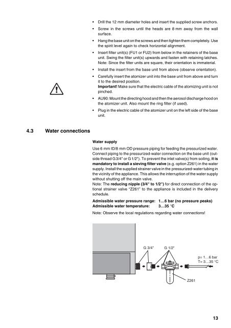
Water supply<br />
Use 6 mm ID/8 mm OD pressure piping for feeding the pressurized water.<br />
Connect piping to the pressurized-water connection on the base unit (outside<br />
thread G3/4" or G1/2"). To prevent the inlet valve(s) from soiling, it is<br />
m<strong>and</strong>atory to install a sieving filter valve (e.g. option Z261) in the water<br />
supply. Install the supplied strainer valve in the pressurized-water tubing in<br />
the vicinity of the appliance. This allows the interruption of the water supply<br />
without shutting off the main valve.<br />
Note: The reducing nipple (3/4" to 1/2") for direct connection of the optional<br />
strainer valve “Z261” to the appliance is included in the delivery<br />
schedule.<br />
Admissible water pressure range: 1…6 bar (no pressure peaks)<br />
Admissible water temperature: 3…35 °C<br />
Note: Observe the local regulations regarding water connections!<br />
G 3/4"<br />
G 1/2"<br />
Z261<br />
p= 1…6 bar<br />
T= 3…35 °C<br />
13