CITY 1.24 and 2.24 GN CITY 1.24 and 2.24 B/P
CITY 1.24 and 2.24 GN CITY 1.24 and 2.24 B/P
CITY 1.24 and 2.24 GN CITY 1.24 and 2.24 B/P

You also want an ePaper? Increase the reach of your titles
YUMPU automatically turns print PDFs into web optimized ePapers that Google loves.
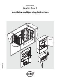
ENGLISH<br />
Wall-hung gas boilers<br />
<strong>CITY</strong> <strong>1.24</strong> <strong>and</strong> <strong>2.24</strong> <strong>GN</strong><br />
<strong>CITY</strong> <strong>1.24</strong> <strong>and</strong> <strong>2.24</strong> B/P<br />
Installation <strong>and</strong><br />
commissioning manual<br />
11/00 - 94858165 - 8666-4118A
CONTENTS<br />
1. GENERAL . . . . . . . . . . . . . . . . . . . . . . . . . . . . . . . . . . . . . . . . . . . . . . . . . . . . . . . . . . . . . . . . . . . . . 3<br />
1.1 Description . . . . . . . . . . . . . . . . . . . . . . . . . . . . . . . . . . . . . . . . . . . . . . . . . . . . . . . . . . . . . . . . 3<br />
1.2 Approvals . . . . . . . . . . . . . . . . . . . . . . . . . . . . . . . . . . . . . . . . . . . . . . . . . . . . . . . . . . . . . . . . . . 3<br />
1.3 Technical specifications . . . . . . . . . . . . . . . . . . . . . . . . . . . . . . . . . . . . . . . . . . . . . . . . . . . . . . . . 4<br />
2. MAIN DIMENSIONS . . . . . . . . . . . . . . . . . . . . . . . . . . . . . . . . . . . . . . . . . . . . . . . . . . . . . . . . . . . . . 5<br />
2.1 Packages . . . . . . . . . . . . . . . . . . . . . . . . . . . . . . . . . . . . . . . . . . . . . . . . . . . . . . . . . . . . . . . . . . 5<br />
2.2 Mounting backplate . . . . . . . . . . . . . . . . . . . . . . . . . . . . . . . . . . . . . . . . . . . . . . . . . . . . . . . . . . . 5<br />
2.3 Installed boiler . . . . . . . . . . . . . . . . . . . . . . . . . . . . . . . . . . . . . . . . . . . . . . . . . . . . . . . . . . . . . . 6<br />
3. SCHEMATICS . . . . . . . . . . . . . . . . . . . . . . . . . . . . . . . . . . . . . . . . . . . . . . . . . . . . . . . . . . . . . . . . . . 7<br />
4. CONTROL PANEL . . . . . . . . . . . . . . . . . . . . . . . . . . . . . . . . . . . . . . . . . . . . . . . . . . . . . . . . . . . . . . .8<br />
5. HYDRAULIC SPECIFICATIONS . . . . . . . . . . . . . . . . . . . . . . . . . . . . . . . . . . . . . . . . . . . . . . . . . . . . .9<br />
5.1 Circulator . . . . . . . . . . . . . . . . . . . . . . . . . . . . . . . . . . . . . . . . . . . . . . . . . . . . . . . . . . . . . . . . . .9<br />
5.2 8 litre expansion tank . . . . . . . . . . . . . . . . . . . . . . . . . . . . . . . . . . . . . . . . . . . . . . . . . . . . . . . . . .9<br />
5.3 12 litre expansion tank (option) . . . . . . . . . . . . . . . . . . . . . . . . . . . . . . . . . . . . . . . . . . . . . . . . . .9<br />
6. INSTALLATION . . . . . . . . . . . . . . . . . . . . . . . . . . . . . . . . . . . . . . . . . . . . . . . . . . . . . . . . . . . . . . . . .9<br />
6.1 Regulations . . . . . . . . . . . . . . . . . . . . . . . . . . . . . . . . . . . . . . . . . . . . . . . . . . . . . . . . . . . . . . . . .9<br />
6.2 Connections . . . . . . . . . . . . . . . . . . . . . . . . . . . . . . . . . . . . . . . . . . . . . . . . . . . . . . . . . . . . . . . .11<br />
6.2.1 Installing the backplate . . . . . . . . . . . . . . . . . . . . . . . . . . . . . . . . . . . . . . . . . . . . . . . . . . .11<br />
6.2.2 Water <strong>and</strong> gas connections . . . . . . . . . . . . . . . . . . . . . . . . . . . . . . . . . . . . . . . . . . . . . . . .11<br />
6.2.3 Water drainage connection . . . . . . . . . . . . . . . . . . . . . . . . . . . . . . . . . . . . . . . . . . . . . . . .12<br />
6.2.4 Installing the boiler . . . . . . . . . . . . . . . . . . . . . . . . . . . . . . . . . . . . . . . . . . . . . . . . . . . . . .12<br />
6.2.5 230 V electrical power supply connection . . . . . . . . . . . . . . . . . . . . . . . . . . . . . . . . . . . . .12<br />
6.2.6 Connection of the Easymatic control or a room thermostat (option) . . . . . . . . . . . . . . . . . . .13<br />
6.3 Pump logic . . . . . . . . . . . . . . . . . . . . . . . . . . . . . . . . . . . . . . . . . . . . . . . . . . . . . . . . . . . . . . . .14<br />
6.4 Fitting the boiler casing . . . . . . . . . . . . . . . . . . . . . . . . . . . . . . . . . . . . . . . . . . . . . . . . . . . . . . .15<br />
7. PRESSURE SETTING AND CALIBRATED INJECTOR AND DIAPHRAGM MARKINGS . . . . . . . . . . .15<br />
8. COMMISSIONING . . . . . . . . . . . . . . . . . . . . . . . . . . . . . . . . . . . . . . . . . . . . . . . . . . . . . . . . . . . . . . .16<br />
8.1 Pre-commissioning checks . . . . . . . . . . . . . . . . . . . . . . . . . . . . . . . . . . . . . . . . . . . . . . . . . . . . .16<br />
8.2 Switching on the boiler . . . . . . . . . . . . . . . . . . . . . . . . . . . . . . . . . . . . . . . . . . . . . . . . . . . . . . . .16<br />
8.3 Filling the installation with water . . . . . . . . . . . . . . . . . . . . . . . . . . . . . . . . . . . . . . . . . . . . . . . . .16<br />
8.4 Igniting the boiler . . . . . . . . . . . . . . . . . . . . . . . . . . . . . . . . . . . . . . . . . . . . . . . . . . . . . . . . . . . .16<br />
8.5 Air bleed . . . . . . . . . . . . . . . . . . . . . . . . . . . . . . . . . . . . . . . . . . . . . . . . . . . . . . . . . . . . . . . . . .17<br />
8.6 Adjusting the domestic hot water flow rate . . . . . . . . . . . . . . . . . . . . . . . . . . . . . . . . . . . . . . . . .17<br />
8.7 Adjustment of the maximum holding temperature of the DHW exchanger . . . . . . . . . . . . . . . . . . .17<br />
8.8 Checks <strong>and</strong> adjustments in service . . . . . . . . . . . . . . . . . . . . . . . . . . . . . . . . . . . . . . . . . . . . . . .18<br />
8.8.1 Burner pressure check . . . . . . . . . . . . . . . . . . . . . . . . . . . . . . . . . . . . . . . . . . . . . . . . . . .18<br />
8.8.2 Burner safety check . . . . . . . . . . . . . . . . . . . . . . . . . . . . . . . . . . . . . . . . . . . . . . . . . . . . .19<br />
8.8.3 Safety thermostat check . . . . . . . . . . . . . . . . . . . . . . . . . . . . . . . . . . . . . . . . . . . . . . . . . .19<br />
8.8.4 Switching off the boiler . . . . . . . . . . . . . . . . . . . . . . . . . . . . . . . . . . . . . . . . . . . . . . . . . . .20<br />
8.8.5 Anti-overflow safety check . . . . . . . . . . . . . . . . . . . . . . . . . . . . . . . . . . . . . . . . . . . . . . . .20<br />
9. MODIFICATION TO USE DIFFERENT GAS . . . . . . . . . . . . . . . . . . . . . . . . . . . . . . . . . . . . . . . . . . . .21<br />
9.1 Removing the burner . . . . . . . . . . . . . . . . . . . . . . . . . . . . . . . . . . . . . . . . . . . . . . . . . . . . . . . . .21<br />
9.2 Replacing the injectors . . . . . . . . . . . . . . . . . . . . . . . . . . . . . . . . . . . . . . . . . . . . . . . . . . . . . . . .22<br />
9.3 Replacing the diaphragm . . . . . . . . . . . . . . . . . . . . . . . . . . . . . . . . . . . . . . . . . . . . . . . . . . . . . .22<br />
9.4 Replacing the gas assembly modulator . . . . . . . . . . . . . . . . . . . . . . . . . . . . . . . . . . . . . . . . . . . .22<br />
9.5 Reassembling . . . . . . . . . . . . . . . . . . . . . . . . . . . . . . . . . . . . . . . . . . . . . . . . . . . . . . . . . . . . . .22<br />
9.6 Adjusting the minimum pressure . . . . . . . . . . . . . . . . . . . . . . . . . . . . . . . . . . . . . . . . . . . . . . . . .23<br />
9.7 “Gas type” label . . . . . . . . . . . . . . . . . . . . . . . . . . . . . . . . . . . . . . . . . . . . . . . . . . . . . . . . . . . . .23<br />
10. MAINTENANCE . . . . . . . . . . . . . . . . . . . . . . . . . . . . . . . . . . . . . . . . . . . . . . . . . . . . . . . . . . . . . . . .24<br />
10.1 Main heat exchanger . . . . . . . . . . . . . . . . . . . . . . . . . . . . . . . . . . . . . . . . . . . . . . . . . . . . . . . . .24<br />
10.2 Burner . . . . . . . . . . . . . . . . . . . . . . . . . . . . . . . . . . . . . . . . . . . . . . . . . . . . . . . . . . . . . . . . . . . .24<br />
10.3 Domestic hot water . . . . . . . . . . . . . . . . . . . . . . . . . . . . . . . . . . . . . . . . . . . . . . . . . . . . . . . . . .25<br />
10.4 Cleaning the ”cold water” filter . . . . . . . . . . . . . . . . . . . . . . . . . . . . . . . . . . . . . . . . . . . . . . . . . .25<br />
11. DRAINING DOWN . . . . . . . . . . . . . . . . . . . . . . . . . . . . . . . . . . . . . . . . . . . . . . . . . . . . . . . . . . . . . .26<br />
12. ELECTRICAL CIRCUIT DIAGRAMS . . . . . . . . . . . . . . . . . . . . . . . . . . . . . . . . . . . . . . . . . . . . . . . . .27<br />
13. FAULT CODES . . . . . . . . . . . . . . . . . . . . . . . . . . . . . . . . . . . . . . . . . . . . . . . . . . . . . . . . . . . . . . . . .29<br />
14. LIST OF SPARES . . . . . . . . . . . . . . . . . . . . . . . . . . . . . . . . . . . . . . . . . . . . . . . . . . . . . . . . . . . . . . .29<br />
15 WARRANTY . . . . . . . . . . . . . . . . . . . . . . . . . . . . . . . . . . . . . . . . . . . . . . . . . . . . . . . . . . . . . . . . . . .37<br />
2
1. GENERAL<br />
1.1 Description<br />
<strong>CITY</strong> <strong>1.24</strong> wall hung gas boilers are for central heating<br />
only. They can be associated with 50, 80 or 150<br />
litre storage tanks to produce domestic hot water.<br />
<strong>CITY</strong> <strong>2.24</strong> boilers provide central heating <strong>and</strong> instantaneous<br />
domestic hot water.<br />
They use natural gas or butane/propane.<br />
<strong>CITY</strong> <strong>1.24</strong> <strong>GN</strong> <strong>and</strong> <strong>CITY</strong> <strong>2.24</strong> <strong>GN</strong> boilers are factory<br />
set for use with natural gas.<br />
<strong>CITY</strong> <strong>1.24</strong> B/P <strong>and</strong> <strong>CITY</strong> <strong>2.24</strong> B/P boilers are factory<br />
set for use with butane/propane.<br />
The boiler output can be varied between 10 <strong>and</strong> 24<br />
kW for central heating <strong>and</strong> 8 <strong>and</strong> 24 kW for domestic<br />
hot water.<br />
1.2 Approvals<br />
3<br />
These boilers are supplied in 2 packs:<br />
- backplate pack: water, gas <strong>and</strong> drain connections<br />
(safety valve, disconnector <strong>and</strong> domestic hot water<br />
pot bleeder on the <strong>2.24</strong> model).<br />
- boiler pack.<br />
Note:<br />
An extended height backplate must be used for boilers<br />
associated with an 80 litre tank.<br />
Boiler <strong>2.24</strong> <strong>GN</strong> <strong>2.24</strong> B/P <strong>1.24</strong> <strong>GN</strong> <strong>1.24</strong> B/P<br />
CE No. CE-0085 AT 0282<br />
Category II 2E+ 3+<br />
Type B11 BS<br />
Combustion product removal Flue liner<br />
Ignition Automatic<br />
Gas Natural gas Butane/Propane Natural gas Butane/Propane<br />
<strong>CITY</strong> boilers conform to the following European directives<br />
<strong>and</strong> st<strong>and</strong>ards:<br />
90/396 EEC Gas appliance directives<br />
Applicable st<strong>and</strong>ards: EN 297 <strong>and</strong> EN 625.<br />
73/23 EEC Low voltage directives<br />
Applicable st<strong>and</strong>ards: EN 60.335.1<br />
89/336 EEC EMC directives<br />
Applicable st<strong>and</strong>ards: EN 50.081.1/<br />
EN 50.082.1./EN 55.014<br />
92/42 EEC Efficiency directives<br />
★★ CE
1.3 Technical specifications<br />
BOILER <strong>1.24</strong> <strong>2.24</strong><br />
Nominal usable output (central heating <strong>and</strong> hot water modes) kW 24 24<br />
Nominal rated output (central heating <strong>and</strong> hot water modes) kW 26.4 26.4<br />
Combustion efficiency % > 92 > 92<br />
Minimum usable output (central heating mode) kW 10 10<br />
Minimum rated output (central heating mode) kW 11.5 11.5<br />
Minimum usable output (domestic hot water mode) kW - 8<br />
Minimum rated output (domestic hot water mode) kW - 9.5<br />
Maximum temperature (safety thermostat trips out) °C 105 105<br />
Weight of boiler without water, backplate, casing kg 30 35<br />
Weight of boiler without water, with backplate <strong>and</strong> casing kg 42 47<br />
Shipping weight<br />
Central heating circuit<br />
kg 47 52<br />
Nominal water flowrate (∆T = 20 K) l/h 1034 1034<br />
Available head bar 0.1 0.1<br />
Outlet temperature °C 40 - 90 40 - 90<br />
Maximum pressure bar 3 3<br />
Expansion tank l 8 8<br />
Initial tank pressure bar 0.75 0.75<br />
Minimum working pressure<br />
Gas flowrate at nominal output<br />
bar 0.3 0.3<br />
Natural gas H (G20) m3 /h 2.79 2.79<br />
Natural gas L (G25) m3 /h 2.97 2.97<br />
Butane (G30) kg/h 2.08 2.08<br />
Propane (G31) kg/h 2.05 2.05<br />
Domestic hot water<br />
Specific hot water flow rate (∆T = 30 K) l/mn - 11.2<br />
Setpoint temperature °C - 40 - 60<br />
Maximum cold water pressure bar - 10<br />
Minimum operating pressure bar - 0.1<br />
Minimum pressure for 11 l/min<br />
Combustion product circuit<br />
bar - 1.3<br />
Connection ø mm 125 125<br />
Minimum draw mbar 0.035 0,035<br />
Combustion product flowrate (nominal output) kg/h 69.5 69.5<br />
Combustion product temperature (nominal output)<br />
Electrical circuit<br />
°C 114 114<br />
Supply voltage (50 Hz) V 230 230<br />
Output consumption W ≅ 80 ≅ 80<br />
1 mbar = 100 Pa<br />
1 daPa ~ 1mm H 2 O<br />
Serial No.<br />
The serial number is on the information plates on the<br />
boiler.<br />
mini<br />
information<br />
plate<br />
information<br />
plate<br />
8666N175<br />
4
2. MAIN DIMENSIONS<br />
2.1 Packages<br />
Pack Number<br />
Boiler Backplate pack Boiler pack<br />
<strong>CITY</strong> <strong>2.24</strong> <strong>GN</strong> HA 10 HA 3<br />
<strong>CITY</strong> <strong>2.24</strong> B/P HA 10 HA 4<br />
<strong>CITY</strong> <strong>1.24</strong> <strong>GN</strong> (50)* HA 9 HA 1<br />
<strong>CITY</strong> <strong>1.24</strong> B/P (50)* HA 9 HA 2<br />
<strong>CITY</strong> <strong>1.24</strong> <strong>GN</strong> (80)* HA 11 HA 1<br />
<strong>CITY</strong> <strong>1.24</strong> B/P (80)* HA 11 HA 2<br />
Pack dimensions<br />
Backplate pack Boiler pack<br />
A<br />
Pack A B C<br />
HA 9<br />
HA 10<br />
860 375 95<br />
HA 11 890 389 139<br />
2.2 Mounting backplate<br />
B<br />
C<br />
St<strong>and</strong>ard backplate for <strong>1.24</strong> <strong>and</strong> <strong>2.24</strong> Increased height backplate for <strong>1.24</strong> / 80L<br />
332<br />
332<br />
27,5<br />
55 55 55 55<br />
153<br />
630<br />
173<br />
20<br />
8666N073<br />
5<br />
* <strong>CITY</strong> <strong>1.24</strong> <strong>GN</strong> <strong>and</strong> <strong>CITY</strong> <strong>1.24</strong> B/P central heating<br />
boilers can be used in conjunction with a 50 or 80<br />
litre storage tank.<br />
If they are associated with an 80 litre storage tank<br />
they can be mounted on an HA 11 increased<br />
height backplate so that the front panel of the<br />
boiler can be lined up with that of the storage tank.<br />
97,5<br />
55 55 55 55<br />
153<br />
630<br />
173<br />
20<br />
1000<br />
570<br />
540<br />
8666N074<br />
8666N075 8666N076
2.3 Installed boiler<br />
<strong>CITY</strong> <strong>1.24</strong> <strong>and</strong> <strong>2.24</strong><br />
450 380<br />
= = Coupling<br />
ring<br />
internal<br />
diameter<br />
125 mm<br />
230<br />
880<br />
8666N077<br />
6<br />
<strong>CITY</strong> <strong>1.24</strong> with increased height backplate<br />
(for lining up with 80 litre domestic hot water storage<br />
tank)<br />
450 450<br />
= = Coupling<br />
ring<br />
internal<br />
diameter<br />
125 mm<br />
300<br />
880<br />
8666N078
3. SCHEMATICS<br />
<strong>2.24</strong> <strong>and</strong> <strong>1.24</strong> boilers<br />
1. Central heating outlet valve<br />
2. Domestic hot water outlet valve<br />
3. Gas inlet valve<br />
4. Cold water inlet valve:<br />
- water flow open / close<br />
- flowrate adjustment<br />
- filter (removable from below)<br />
5. Central heating return valve<br />
6. Drain screw<br />
7. Water flowrate sensor<br />
8. Domestic hot water outlet sensor<br />
9. Domestic hot water heat<br />
exchanger drain screw<br />
10. Domestic hot water heat exchanger<br />
maintain temperature sensor<br />
11. Domestic hot water heat<br />
exchanger air bleed screw<br />
12. Central heating / domestic hot<br />
water changeover valve drive motor<br />
13. Central heating / domestic hot<br />
water changeover valve<br />
14. Electronic pressure gauge<br />
15. Degassing chamber<br />
16. Circulator motor<br />
17. Burner pressure offtake<br />
18. Ionisation sensor<br />
19. Expansion tank<br />
20. Expansion tank inflation valve<br />
21. Automatic bleeder<br />
22. Anti-backflow draw cup-out<br />
23. Combustion product connector<br />
24. Combustion product anti-overflow<br />
sensor<br />
25. Main heat exchanger<br />
26. Central heating outlet temperature<br />
sensor<br />
27. Safety thermostat<br />
28. Combustion chamber<br />
29. Burner<br />
30. Igniter electrodes<br />
31. Gas valve modulator<br />
32. Gas valve safety valves<br />
33. Gas supply pressure offtake<br />
34. Modulator gas valve<br />
35. Domestic hot water heat<br />
exchanger (<strong>2.24</strong> only)<br />
36. Central heating circuit safety valve<br />
37. Central heating circuit by-pass pipe<br />
38. Disconnector<br />
42. Igniter<br />
43. Domestic hot water flow rate<br />
controller (10 l/min)<br />
44. Non return valve<br />
* If boiler is connected to domestic hot<br />
water storage tank<br />
24<br />
25<br />
26<br />
27<br />
28<br />
29<br />
30<br />
31<br />
32<br />
42<br />
33<br />
34<br />
35<br />
44<br />
36<br />
37<br />
38<br />
7<br />
TS<br />
TAF<br />
S1<br />
Central<br />
heating<br />
6<br />
M<br />
2<br />
1<br />
M<br />
2<br />
1<br />
S2<br />
S3<br />
6 6 6<br />
outlet<br />
1 2 3 4 5<br />
Central<br />
heating<br />
outlet<br />
D.H.W.<br />
Domestic*<br />
hot water<br />
storage tank<br />
primary outlet<br />
Gas<br />
inlet<br />
D.C.W. Central<br />
heating<br />
return<br />
gas Domestic*<br />
inlet hot water<br />
storage tank<br />
primary return<br />
Central<br />
heating<br />
return<br />
<strong>CITY</strong> <strong>2.24</strong><br />
23<br />
22<br />
21<br />
20<br />
19<br />
18<br />
17<br />
16<br />
15<br />
14<br />
13<br />
12<br />
11<br />
10<br />
43 9<br />
8<br />
7<br />
<strong>CITY</strong> <strong>1.24</strong><br />
8666N016F
4. CONTROL PANEL<br />
A B B1 B2 C D E F<br />
G H I J K L<br />
M<br />
A. Temperature display<br />
- displays the temperature at the central heating<br />
outlet or the domestic hot water outlet when water<br />
is drawn off.<br />
B. Domestic hot water heat exchanger temperature<br />
button (<strong>CITY</strong> <strong>2.24</strong> only).<br />
This function is factory set to the activated<br />
position.<br />
This provides maximum user comfort.<br />
When the boiler is switched on, indicator B2 is on<br />
to show that this function is activated.<br />
The function can be deactivated, for example in<br />
the event of prolonged absence, by pressing button<br />
B (indicator B2 turns off).<br />
Disconnection of the output supply does not modify<br />
the selected operating mode.<br />
Note:<br />
- if indicators B1 <strong>and</strong> B2 are both turned on, the<br />
burner has been ignited to heat the domestic hot<br />
water supply.<br />
- B2 flashes when the holding position is activated<br />
by bypassing the Easymatic control.<br />
C. Safety indicator<br />
D. Unlocking button<br />
- used to reset the boiler from failsafe mode<br />
E. “clean” button<br />
- forces operation of the boiler<br />
• press <strong>and</strong> hold for 5 seconds (display shows )<br />
to force the burner to the P min position<br />
• press again (display shows ) to force<br />
the burner to the P max (24 kW) position<br />
8<br />
F. “Installer” button<br />
8666N020<br />
G. 3-position switch<br />
- off/anti-freeze<br />
- central heating <strong>and</strong> domestic hot water (winter)<br />
- domestic hot water (summer)<br />
H. “Central heating” on indicator<br />
- on when the boiler is ignited to heat the water in<br />
the central heating circuit<br />
I. Central heating temperature control<br />
- range from 40 to 90°C (click stop at 75°C)<br />
J. Flame present indicator<br />
- on when the burner is ignited<br />
K. Domestic hot water temperature control<br />
- range from 40 to 60°C (click stop at 55°C)<br />
L. “Domestic hot water” on indicator<br />
- on when the burner is ignited to heat the domestic<br />
hot water supply<br />
M. Pressure indicator<br />
- indicates the pressure in the central heating<br />
circuit (0.5 to 2.5 bars)
5. HYDRAULIC SPECIFICATIONS<br />
5.1 Circulator<br />
The circulator incorporated in the boiler is equipped<br />
with a 3-speed motor with a output consumption of<br />
80 W supply. It is factory-set on high.<br />
Remark<br />
For boilers also producing domestic hot water (City<br />
<strong>2.24</strong> or <strong>1.24</strong> plus storage cylinder), the circulator can<br />
if required be set on intermediate. It is nevertheless<br />
recommended, for reasons of comfort, to leave it on<br />
high.<br />
For installations requiring greater hydraulic performance<br />
it is possible to replace the motor with a more<br />
outputful one (pack HA 209) with a output consumption<br />
of 93 W.<br />
5.2 8 litre expansion tank<br />
<strong>CITY</strong> boilers are equipped as st<strong>and</strong>ard with an 8 litre<br />
tank (initial pressure 0.75 bar). The total water volume<br />
is determined in accordance with the static head<br />
of the installation <strong>and</strong> for an average water temperature<br />
of 80°C (flow: 90/return:70).<br />
5.3 12 litre expansion tank<br />
<strong>CITY</strong> boilers can optionally be fitted with a 12 litre<br />
expansion tank (initial pressure 0.75 bar) (pack HA<br />
208).<br />
6. INSTALLATION<br />
6.1 Regulations<br />
Installation <strong>and</strong> maintenance regulations<br />
The appliance must be installed <strong>and</strong> maintained by a<br />
qualified professional in accordance with statutory<br />
requirements.<br />
9<br />
Head (mcE)<br />
6<br />
5<br />
4<br />
3<br />
2<br />
1<br />
GV<br />
MV<br />
PV<br />
GV<br />
MV<br />
PV<br />
0<br />
0 200 400 600 800 1000 1200<br />
Flowrate (l/h)<br />
8666N079<br />
1. PV : low speed<br />
2. MV : medium speed<br />
3. GV : high speed<br />
Static head 5 6 7 8 9 10<br />
in metres up to<br />
Total water<br />
volume<br />
Establishments receiving the public<br />
Installation regulations:<br />
80 W motor<br />
93 W motor (option)<br />
138 129 120 111 102 92<br />
Static head 5 6 7 8 9 10<br />
in metres up to<br />
Total water<br />
volume<br />
213 204 195 186 177 167<br />
The appliance must be installed <strong>and</strong> maintained in<br />
accordance with statutory requirements.
15 mm<br />
mini<br />
15 mm<br />
mini<br />
- The connection to the flue must be as short <strong>and</strong><br />
direct as possible.<br />
- Do not install the boiler over a cooker.<br />
8666N089<br />
- The boiler must be fixed to a solid wall capable of<br />
supporting the weight of the appliance when filled<br />
with water <strong>and</strong> associated equipments.<br />
- A 15 mm gap on either side of the boiler is sufficient<br />
for removing <strong>and</strong> replacing the casing. However, a<br />
50 mm gap is recommended to facilitate maintenance.<br />
- The boiler must not be installed above a heat source<br />
or a cooker.<br />
- The IPX4D protection index authorises installation<br />
in bathrooms, but outside protection level 1 <strong>and</strong> 2<br />
volumes.<br />
Ventilation of the room in which the boiler is installed<br />
Fresh air supply<br />
In the case of direct fresh air entry, the minimum area<br />
required is 50 cm 2.<br />
Vitiated air extraction<br />
If the boiler is installed in a kitchen, for example, vitiated<br />
air from appliances not connected to an extractor<br />
pipe (gas cooker, etc.) can be extracted via the draw<br />
cup of the boiler. For this it is sufficient for the top of<br />
the boiler casing to be at least 1.8 m above the floor.<br />
10<br />
10 cm<br />
mini *<br />
48 cm<br />
mini<br />
S2<br />
S1<br />
55 cm<br />
mini<br />
30 cm<br />
mini<br />
5 cm<br />
either side of<br />
the boiler<br />
S1 <strong>and</strong> S2 : Minimum 600 cm 2 unimpeded area<br />
10 cm min * : Distance between front of boiler<br />
<strong>and</strong> inside of closure panel<br />
8666N090<br />
The installation must comply with applicable regulations.<br />
Thermostatic radiator valves must not be used on all<br />
radiators.<br />
The <strong>CITY</strong> boiler incorporates a by-pass assuring a<br />
minimum flow of 200 l/h.<br />
Radiators in rooms containing a room thermostat<br />
must not be fitted with thermostatic valves.<br />
Note:<br />
We would draw your attention to the risk of corrosion<br />
of boilers installed or near rooms in which the atmosphere<br />
may be polluted by substances containing chlorine<br />
or fluorine. Examples are: hairdressing salons,<br />
industrial premises (solvents), refrigeration plants, etc.<br />
The warranty does not cover such installations.
6.2 Connections<br />
Important notes:<br />
• Before connecting the boiler to an existing installation,<br />
the installation must be thoroughly rinsed out<br />
using an appropriate product to prevent sludge reaching<br />
the heater body of the new boiler.<br />
6.2.1 Installing the backplate<br />
See the installation instruction sheet supplied in the<br />
backplate pack.<br />
6.2.2 Water <strong>and</strong> gas connections<br />
With 8 or 12 litre expansion tanks, the connections<br />
can be made from below, from above or from the rear.<br />
• Central heating connection<br />
Copper bush for connection to 16/18 mm dia. indoor<br />
tube or 20/22 mm dia. outdoor tube.<br />
• Domestic hot water connection<br />
Copper bush for connection to 14/16 mm dia. indoor<br />
tube or 18/20 mm dia. outdoor tube.<br />
In hard water areas (hardness >25) we recommend a<br />
water softener upstream of the boiler.<br />
• Gas connection<br />
Conform to the applicable provisions <strong>and</strong> in particular<br />
gas installation specification. A shut-off valve must<br />
always be installed as close as possible to the boiler.<br />
The copper bush is for 16/18 mm dia. indoor copper<br />
tube.<br />
Operating pressure<br />
20 mbar for H natural gas H (G20)<br />
25 mbar for H natural gas L (G25)<br />
29 mbar for butane (G30)<br />
37 mbar for propane (G31)<br />
11<br />
• If different metals are used, such as copper <strong>and</strong> aluminium,<br />
a corrosion inhibitor must be used.<br />
Central<br />
heating outlet<br />
ø18<br />
Tube-cutter<br />
D.H.W<br />
ø16<br />
Gas<br />
inlet<br />
ø18<br />
Connections<br />
D.C.W<br />
ø16<br />
From the rear<br />
From above<br />
From below<br />
Central<br />
heating return<br />
ø18<br />
ø18 od ø16 od ø18 od ø16 od ø18 od<br />
ø20 id ø18 id ø18 id ø20 id<br />
8666N130<br />
All nested connections to the gas tube must be<br />
made using sleeves purchased off the shelf.<br />
8666N081
6.2.3 Water drain connection<br />
6.2.4 Installing the boiler<br />
1<br />
The 32 mm diameter “waste water” drainage<br />
connection supplied with the backplate<br />
must be fitted only after brazing the copper<br />
tubes.<br />
It is P19 fixed to the left-h<strong>and</strong> upright of the<br />
backplate using a 12 mm long 4 mm diameter<br />
screw.<br />
Evacuation to a drain is by means of a<br />
syphon.<br />
Remove the plastic plugs from the boiler<br />
pipes.<br />
2 Offer up the boiler above the valve bracket so that<br />
it backs onto the backplate.<br />
3 Lower the boiler gently. Fit the 5 seals supplied in<br />
the sachet with the manual.<br />
4 Remove the retaining pins <strong>and</strong> tighten the nuts.<br />
6.2.5 230 V electrical main supply connection<br />
<strong>CITY</strong> boilers are fitted with a 3-core main supply<br />
cable approximately 1.5 m long.<br />
For correct electrical installation, the appliance must<br />
be connected to a socket outlet or a circuit including<br />
a 2-pole switch with an open contact spacing greater<br />
than 3 mm.<br />
Electrical connections must be made by a<br />
qualified professional.<br />
Note:<br />
When connecting to the mains electrical main<br />
supply, connect the brown wire to live <strong>and</strong> the<br />
blue wire to neutral.<br />
If these connections are reversed the ionisation<br />
type flame detector will not operate. The<br />
boiler will then go to the fail-safe mode.<br />
12<br />
8666N088 B<br />
1<br />
4<br />
brown to live<br />
blue to neutral<br />
grenn/yellow to earth<br />
3<br />
2<br />
marron sur phase<br />
8666N087<br />
8666N091 A
6.2.6 Connection of the Easymatic control or a<br />
room thermostat (option)<br />
The options are to be connected at the back of the<br />
control panel under the small flap.<br />
- Pivot the panel forwards after unscrewing the 2 fastening<br />
side screws.<br />
- Pull the small flap towards you <strong>and</strong> ensure that the<br />
connections are in accordance with the selected<br />
options.<br />
• Easymatic communicative remote control<br />
(box AD 136)<br />
- see the instructions delivered with the Easymatic<br />
remote control.<br />
• Programmable room thermostat<br />
(box AD 137)<br />
- remove the resistance from the Room Thermostat<br />
connector<br />
- connect, in any order, terminals 1 <strong>and</strong> 3 of the<br />
thermostat to the terminals of the Room Thermostat<br />
connector.<br />
- see also the instructions delivered with the thermostat.<br />
• Non-programmable room thermostat<br />
(box AD 140)<br />
- remove the resistance from the Room Thermostat<br />
connector<br />
- connect, in any order, terminals 1 <strong>and</strong> 4 of the<br />
thermostat to the terminals of the Room Thermostat<br />
connector.<br />
- see also the instructions delivered with the thermostat.<br />
Note : If a room thermostat with 2 dry-contact wires<br />
has been installed, it may be used.<br />
For this:<br />
- remove the resistance from the Room Thermostat<br />
connector<br />
- connect, in any order, the 2 thermostat wires to the<br />
terminals of the Room Thermostat connector.<br />
Remark:<br />
Connections can be with either a 2 wire telephone cable<br />
or an electrical section cable of up to 2 x 1,5 mm 2 .<br />
13<br />
BUS TAM<br />
SB<br />
BUS TAM SB<br />
1 2 3<br />
8666N094
6.3 Pump Logic<br />
1. In mode (domestic hot water) or in Easymatic<br />
mode (summer), the pump works when<br />
domestic hot water is produced (d.h.w), <strong>and</strong> cuts<br />
off 30 seconds after the d.h.w has been produced;<br />
the inversion valve will remain in the d.h.w. position.<br />
2. In mode (heating + d.h.w.)<br />
A. Without a Room Thermostat or Easymatic<br />
The pump will work continuously.<br />
B. With a Room Thermostat<br />
• Switch in position 1:<br />
Continuous operation of the pump.<br />
• Switch in position 2:<br />
- The pump cuts off 15 minutes after starting<br />
the Room Thermostat.<br />
- After production of d.h.w., if the Room Thermostat<br />
is started up, the pump cuts off after<br />
30 seconds <strong>and</strong> the inversion valve remains in<br />
the d.h.w. position.<br />
• Switch in position 3:<br />
- The pump cuts off 30 seconds after starting<br />
the Room Thermostat<br />
- After production of d.h.w., if the room thermostat<br />
is started up, the pump cuts off after<br />
30 seconds <strong>and</strong> the inversion valve remains in<br />
the d.h.w. position.<br />
C. With an Easymatic:<br />
• Switch in position 1 or 2:<br />
Continuous operation of the pump.<br />
• Switch in position 3:<br />
- When the room temperature is correct, the<br />
pump remains in continuous operation.<br />
- When the room temperature is too high, the<br />
pump cuts off after 15 minutes.<br />
- After the production of d.h.w., if the room<br />
temperature is too high the pump cuts off<br />
after 30 seconds <strong>and</strong> the inversion valve<br />
remains in the d.h.w. position<br />
3. In mode<br />
The pump is stopped.<br />
If need be, when the room temperature falls below<br />
10° C, the pump will start up to prevent the boiler<br />
from freezing.<br />
14<br />
1 2 3<br />
BUS TAM SB<br />
1 2 3<br />
8666N124A
6.4 Fitting the boiler casing<br />
8666N092<br />
7. PRESSURE SETTING AND CALIBRATED INJECTOR AND DIAPHRAGM<br />
MARKINGS<br />
Equipment<br />
<strong>CITY</strong> <strong>1.24</strong> <strong>and</strong> <strong>2.24</strong><br />
Burner pressure <strong>and</strong> gas flow rate<br />
<strong>CITY</strong> <strong>1.24</strong> <strong>and</strong> <strong>2.24</strong><br />
ø<br />
mm<br />
Burner Natural gas H <strong>and</strong> L 1.35<br />
injectors Butane / Propane 0.8<br />
Diaphragm Natural gas H <strong>and</strong> L 5.2<br />
Butane / Propane 4.2<br />
Output nominal minimum<br />
Burner Nat. gas H mbar 6.5 1.0<br />
pressure Nat. gas L mbar 7.9 1.4<br />
Butane mbar 19.1 2.5<br />
Propane mbar 24.1 3.4<br />
Flow Nat. gas H m 3 /h 2.79 1.01<br />
rate * Nat. gas L m 3 /h 2.97 1.07<br />
Butane kg/h 2.08 0.75<br />
Propane kg/h 2.05 0.74<br />
15<br />
Note : fit the front panel after commissioning<br />
the boiler.<br />
* 1013 mbar at 15°C<br />
8666N093
8. COMMISSIONING<br />
Commissioning must be carried out by a qualified<br />
professional<br />
8.1 Pre-commissioning checks<br />
- Check on the boiler label that it is set up for the gas<br />
in use.<br />
- If not, see chapter 9 “Modification to use a different<br />
gas”.<br />
- Open the gas valve 3.<br />
- Take out the 2 fixing screws at the sides <strong>and</strong> swing<br />
the control panel forward.<br />
- Check the pressure of the gas supply to the boiler<br />
at the pressure offtake on the gas valve (33) against<br />
the information plate.<br />
- Close the gas pressure offtake screw.<br />
- Check for gas <strong>and</strong> water leaks.<br />
Return the control panel to its original position <strong>and</strong><br />
replace the 2 fixing screws at the sides.<br />
8.2 Switching on the boiler<br />
Check the 3-position switch G is set to “off/anti-freeze”<br />
<strong>and</strong> then switch on the boiler by plugging in the<br />
plug or operating the isolating switch.<br />
8.3 Filling the installation with water<br />
- Open valves 1-2*-4* <strong>and</strong> 5.<br />
- Check that the automatic bleeder 21 at the top of the<br />
expansion tank is open.<br />
- Fill the installation to a pressure of 1.5 to 2 bars via<br />
valves 38.1 <strong>and</strong> 38.2.<br />
- Close valves 38.1 <strong>and</strong> 38.2 when the installation<br />
has been filled with water.<br />
* <strong>CITY</strong> with domestic hot water production.<br />
8.4 Igniting the boiler<br />
- Set the switch to the position marked .<br />
- If there is a room thermostat or a communicating<br />
remote controller, set it to call for heat.<br />
16<br />
33<br />
38.1<br />
G<br />
38.2 1<br />
2*<br />
4*<br />
3<br />
8666N180<br />
8666N096<br />
5 8666N098 B<br />
8666N097
8.5 Air bleed<br />
1<br />
2<br />
Open the stopper of the automatic bleeder in<br />
the top rear corner of the boiler.<br />
Domestic hot water heat exchanger<br />
(<strong>CITY</strong> <strong>2.24</strong> only)<br />
- Bleed the domestic hot water heat exchanger<br />
by unscrewing the bleeder slightly.<br />
- To accelerate bleeding, alternate between<br />
calling for heat <strong>and</strong> hot water.<br />
- Tighten the bleeder after bleeding the air.<br />
Central heating installation<br />
- Check that all of the installation has been bled<br />
correctly.<br />
8.6 Adjusting the domestic hot water flow rate<br />
(<strong>CITY</strong> <strong>2.24</strong> only)<br />
The maximum domestic hot water flow rate is limited<br />
to 10 l/min by the flow rate controller which is mounted<br />
on the flow rate detector (item 43 § 3).<br />
This maximum flow rate can be reduced in 2 ways:<br />
- 1. by adjusting the screw 4.1 (8 mm Allen key),<br />
- 2. by replacing the 10 l/min controller with an<br />
8 l/min controller.<br />
The 8 l/min controller (package HA 218) is supplied<br />
with fitting instructions.<br />
17<br />
8666N105 A<br />
8.7 Adjustment of the maximum temperature position of the DHW exchanger : T MM<br />
(<strong>CITY</strong> <strong>2.24</strong> only)<br />
The DHW exchanger, when activated, is maintained<br />
at the projected holding temperature DHW - 5° C or<br />
at the maximum T MM.<br />
Adjustment Display<br />
- Press the button for 5 seconds (55°C)<br />
- Press repeatedly to select the desired<br />
maximum temperature position TMM<br />
To exit the display, wait 5 minutes without<br />
pressing anything<br />
1<br />
2<br />
4.1<br />
8666N106 B
8.8. Checks <strong>and</strong> adjustments in service<br />
8.8.1 Burner pressure check<br />
- Unscrew the screw inside the burner pressure offtake<br />
17 a few turns.<br />
- Connect a pressure gauge to the pressure offtake<br />
<strong>and</strong> verify that the pressure corresponds to that indicated<br />
in chapter 7.<br />
Checking the burner pressure at nominal (max)<br />
output:<br />
Force the burner to operate at maximum output by<br />
pressing the button marked E :<br />
- Press <strong>and</strong> hold down the “clean” button E for<br />
5 seconds. The display A indicates .<br />
- Press button E briefly. The display A indicates .<br />
Check that the measured pressure corresponds to<br />
that indicated in chapter 7.<br />
If there is any significant difference, check that the<br />
boiler is equipped for the gas supplied as indicated in<br />
the table in chapter 7.<br />
To revert to normal operation press button E briefly.<br />
- Remember to close the pressure offtake<br />
screw 17 after measuring the pressure.<br />
- Check the pressure offtake 17 for gas<br />
leaks.<br />
18<br />
A<br />
17<br />
E<br />
8666N104 A<br />
8666N107A
8.8.2 Burner safety check<br />
- With the burner lit, cut off the gas supply by closing<br />
the shut-off valve.<br />
- Check the reaction of the safety system:<br />
the alarm indicator C should turn on <strong>and</strong> the display<br />
A should alternately indicate <strong>and</strong> .<br />
- Open the gas valve <strong>and</strong> press the reset button D.<br />
8.8.3 Safety thermostat check<br />
The safety thermostat should shut down the boiler if<br />
the temperature at the central heating outlet exceeds<br />
105°C.<br />
- Press the “clean” button E for 5 seconds. The dis-<br />
play A shows .<br />
- Press button E briefly. The display A shows .<br />
- Press button E a third time for 5 seconds. This<br />
forces the burner to minimum output <strong>and</strong> the display<br />
A indicates alternately <strong>and</strong> the original temperature.<br />
- Close the central heating flow <strong>and</strong> return valves 1 <strong>and</strong><br />
5 using an 8 mm wrench.<br />
The outlet temperature is no longer limited by the<br />
control system <strong>and</strong> the safety thermostat should shut<br />
down the burner.<br />
When the temperature exceeds 100°C <strong>and</strong> the safety<br />
thermostat has not yet tripped, the display indicates<br />
alternately <strong>and</strong> .<br />
If the burner is turned off, the boiler cools <strong>and</strong> shortly<br />
afterwards the burner is ignited again <strong>and</strong> the rise<br />
in temperature continues:<br />
- when the burner is shut off by the safety thermostat:<br />
• indicator C turns on<br />
• the display alternately indicates <strong>and</strong> .<br />
- To restart the burner:<br />
• open central heating flow <strong>and</strong> return valves 1<br />
<strong>and</strong> 5<br />
• press button D.<br />
19<br />
8666N111 A<br />
8666N218<br />
8666N219<br />
A C D<br />
A<br />
1 5<br />
A<br />
8666N108 B<br />
If the boiler has not shut down 2 minutes<br />
after shutting the valves, disconnect the boiler<br />
from the mains electrical output supply.<br />
E<br />
C D
8.8.4 Switching off the boiler<br />
Set switch G to “off/anti-freeze”:<br />
The boiler goes to the st<strong>and</strong>by mode <strong>and</strong> the display<br />
indicates<br />
Note: In this operating mode only the boiler is<br />
protected against freezing.<br />
8.8.5 Anti-overflow safety check<br />
If fumes overflow through the anti-backflow device,<br />
the anti-overflow safety device 24 disconnects the<br />
electrical output supply to the valve <strong>and</strong> the boiler<br />
goes to its fail-safe mode.<br />
The anti-overflow device must be checked on commissioning<br />
the boiler <strong>and</strong> during annual maintenance.<br />
Check procedure:<br />
- Turn off the boiler by setting the 3-position switch G<br />
to “off/anti-freeze”.<br />
- Remove the pipe connecting the boiler to the flue.<br />
- Using a sheet of metal (or any other heat-resistant<br />
material), block the combustion product outlet of the<br />
boiler.<br />
- Start the boiler; combustion products are evacuated<br />
in the upper part of the boiler via the openings in the<br />
anti-backflow device.<br />
- The anti-overflow sensor disconnects the electrical<br />
output supply from the gas valve within 2 minutes.<br />
The burner is turned off.<br />
- After completing the check, replace the pipe<br />
connecting the boiler to the flue. The boiler restarts<br />
automatically after about 10 minutes.<br />
Note: To avoid this time delay it is sufficient to switch off<br />
the mains electrical output supply <strong>and</strong> switch it on<br />
again.<br />
20<br />
G<br />
24<br />
8666N096<br />
8666N118
9. MODIFICATION TO USE DIFFERENT GAS<br />
<strong>CITY</strong> <strong>2.24</strong> <strong>GN</strong> <strong>and</strong> <strong>1.24</strong> <strong>GN</strong> boilers are equipped to<br />
use natural gas. <strong>CITY</strong> <strong>2.24</strong> B/P <strong>and</strong> <strong>1.24</strong> B/P boilers<br />
are equipped to use butane/propane.<br />
The procedure from changing from one gas to the<br />
other is as follows:<br />
9.1 Removing the burner<br />
9.2 Replacing the injectors<br />
9.3 Replacing the diaphragm<br />
9.4 Replacing the gas assembly modulator<br />
9.5 Reassembling<br />
9.6 Adjusting the minimum pressure<br />
9.7 “Gas type” label<br />
9.1 Removing the burner<br />
1<br />
2<br />
3<br />
4<br />
5<br />
6<br />
7<br />
8<br />
Disconnect the electrical output supply<br />
<strong>and</strong> the gas supply from the boiler.<br />
Remove the front panel from the boiler casing (2<br />
screws at the top).<br />
Remove the front plate from the combustion<br />
chamber (2 screws at the top + 2 wing-nuts).<br />
Disconnect the 2 igniter electrodes.<br />
Disconnect the wire from the ionisation sensor.<br />
Remove the anti-radiation plate by pulling it<br />
forwards.<br />
Unscrew the 3/4” nut at the top of the gas<br />
valve.<br />
Unscrew the 4 screws fixing the burner to the<br />
manifold. Use a magnetic screwdriver if possible.<br />
Remove the burner, the diaphragm <strong>and</strong> the 2<br />
seals.<br />
21<br />
8<br />
8666N178<br />
3<br />
5<br />
The operations described below<br />
must be carried out by a qualified<br />
professional.<br />
1<br />
2<br />
4<br />
7<br />
6<br />
8666N177
9.2 Replacing the injectors<br />
7<br />
9.5 Reassembling<br />
Reassembly is the reverse procedure to disassembly.<br />
- Connect the igniter electrode.<br />
- Connect the ionisation sensor.<br />
- Replace the anti-radiation plate.<br />
8666N201<br />
Replace the injectors <strong>and</strong> the seals (see chapter 7).<br />
9.4 Replacing the gas assembly modulator<br />
1<br />
2<br />
3<br />
Disconnect the two wires from the modulator.<br />
Unscrew the 2 screws retaining the modulator<br />
using a Torx No. 20 wrench.<br />
Replace the modulator <strong>and</strong> the seal, checking<br />
that the seal <strong>and</strong> the spacer seat correctly.<br />
● Modulator with grey cap =<br />
natural gas, modulator mark:<br />
1.5 - 20 mbar.<br />
● Modulator with yellow cap =<br />
butane/propane, modulator mark:<br />
3 - 37 mbar.<br />
Reconnect the 2 wires to the modulator.<br />
22<br />
9.3 Replacing the diaphragm<br />
3<br />
2<br />
1<br />
- Replace the combustion chamber side <strong>and</strong> front<br />
plates.<br />
- Switch on <strong>and</strong> open the gas supply.<br />
Check for gas leaks.<br />
8666N179<br />
When replacing the burner, fit the new diaphragm to the<br />
gas assembly between 2 new seals. See chapter 7.<br />
8666N184
9.6 Adjusting the minimum pressure<br />
Natural gas H <strong>and</strong> L, butane <strong>and</strong> propane.<br />
Adjust the pressure at the burner downstream of the<br />
gas assembly. The values to set are indicated in<br />
chapter 7.<br />
Measure the pressure at the boiler by connecting a<br />
pressure gauge to pressure offtake 17, as follows:<br />
1<br />
2<br />
3<br />
4<br />
5<br />
6<br />
Remove the screw retaining the plastic cover.<br />
Remove the cover.<br />
Verify that the “maximum flowrate” plastic nut is<br />
screwed fully home.<br />
Force operation of the boiler at the minimum output<br />
setting by pressing the “clean” button E <strong>and</strong><br />
holding it down for 5 seconds (see section 4).<br />
Adjust the minimum pressure with the brass nut.<br />
- Turning the nut clockwise increases the<br />
pressure.<br />
- Turning the nut anti-clockwise<br />
reduces the pressure.<br />
After completing the adjustment, replace the<br />
cap.<br />
To revert to normal operation, press button E briefly.<br />
Disconnect the pressure gauge.<br />
Screw in the screw of the pressure offtake.<br />
Check for gas leaks.<br />
9.7 “Gas type” label<br />
Affix the label indicating the type of gas for which the<br />
boiler is equipped <strong>and</strong> set up.<br />
23<br />
2<br />
8666N183<br />
1<br />
3<br />
5<br />
17<br />
8666N104 A<br />
8666N122
10. MAINTENANCE<br />
Maintenance operations must be carried out by a<br />
qualified professional.<br />
10.1 Main heat exchanger<br />
Periodically check the main heat exchanger for soiling.<br />
If necessary remove the heat exchanger <strong>and</strong> wash it<br />
with very hot water containing a detergent.<br />
1<br />
2<br />
3<br />
4<br />
5<br />
6<br />
10.2 Burner<br />
Disconnect the electrical output supply<br />
<strong>and</strong> the gas supply from the boiler. Close<br />
the boiler isolating valves <strong>and</strong> open the<br />
drain screws.<br />
Remove the boiler casing front panel (2 screws<br />
at the top).<br />
Remove the front plate from the combustion<br />
chamber (2 screws at the top + 2 wing nuts).<br />
Remove the anti-radiation plate.<br />
Remove the side plates of the combustion<br />
chamber.<br />
Unscrew the 3/4" nuts of the heat exchanger<br />
(30 mm wrench).<br />
Remove the main heat exchanger by pulling it<br />
towards you.<br />
Note:<br />
When refitting the main exchanger:<br />
- grease the threads of the connectors<br />
- replace the seals<br />
- tighten the nuts moderately<br />
Check the condition of the burner annually.<br />
Use a dry soft brush to clean the burner, or wash it<br />
with hot water containing a detergent. Rinse thoroughly.<br />
For instructions on removing the burner, see section<br />
9.1.<br />
24<br />
6<br />
30<br />
1<br />
2<br />
3<br />
4<br />
5<br />
4<br />
8666N176<br />
5<br />
8666N119 A
10.3 Domestic hot water<br />
If the domestic hot water heat exchanger is affected<br />
by limescale, clean it by connecting a descaling<br />
pump to the two domestic water connectors ➂.<br />
Use only products suitable for this purpose.<br />
To obtain access to the domestic water connectors:<br />
1 Tilt the control panel forward after removing the<br />
2 fixing screws at the sides.<br />
2<br />
3<br />
4<br />
5<br />
6<br />
7<br />
8<br />
Disconnect the electrical output supply<br />
<strong>and</strong> the gas supply from the boiler.<br />
Close the domestic water inlet <strong>and</strong> outlet<br />
valves <strong>and</strong> open the drain screws.<br />
Protect the control panel from being<br />
splashed with descaling product.<br />
Unscrew the two 1/2”nuts on the domestic water<br />
heat exchanger (24 mm wrench).<br />
Unscrew slightly the 3/4” nut on the domestic<br />
hot water outlet (30 mm wrench).<br />
Pivot the domestic hot water outlet tube towards<br />
the front.<br />
Unscrew the 3/4" nut on the domestic cold water<br />
inlet pipe (30 mm wrench).<br />
Remove the domestic cold water inlet pipe.<br />
Connect the descaling device to the two 1/2"<br />
exchanger connectors.<br />
After descaling, reassembly is the reverse of the<br />
above procedure.<br />
Replace the seals with new seals.<br />
10.4 Cleaning the ”cold water” filter<br />
(<strong>CITY</strong> <strong>2.24</strong> only)<br />
1<br />
2<br />
3<br />
4<br />
Turn the tap off (6mm spanner) to avoid any drawing<br />
off from the domestic circuit (kitchen,<br />
bathroom, etc.) <strong>and</strong> major discharge when the<br />
filter is dismantled.<br />
Unscrew the drain cock after connecting a hose<br />
(dimension: 8 mm).<br />
Unscrew the adjustment door-filter-tap with a<br />
17mm spanner.<br />
If required, remove the filter <strong>and</strong> clean it with a<br />
soft brush<br />
- replace the filter on the filter-door <strong>and</strong> screw it<br />
into the tap (17mm spanner)<br />
- turn off the drain cock<br />
- turn on the tap (6mm spanner).<br />
25<br />
1<br />
�<br />
5<br />
3<br />
7<br />
4 6<br />
�<br />
�<br />
8666N182<br />
�<br />
8666N293
11. DRAINING DOWN<br />
To drain down the boiler:<br />
- Close gas valve 3, water valves 1, 2, 5<br />
(8 mm wrench) <strong>and</strong> 4 (6 mm wrench).<br />
- Connect an 8 mm internal diameter hose to drain<br />
screw 6.<br />
- Unscrew the drain screw.<br />
26<br />
6<br />
6*<br />
4*<br />
6*<br />
* Boiler prepared for domestic hot water supply.<br />
1<br />
6<br />
2*<br />
3<br />
5<br />
8666N117 B
12. ELECTRICAL CIRCUIT DIAGRAMS<br />
<strong>CITY</strong> <strong>2.24</strong> with flue liner<br />
8806-5112<br />
10 14<br />
J18 J1<br />
1<br />
2<br />
3<br />
1<br />
2<br />
3<br />
J15 J13<br />
J6<br />
J8<br />
8806-5111<br />
J17<br />
1<br />
2<br />
J12<br />
J2<br />
J10<br />
1<br />
2<br />
3<br />
4<br />
5<br />
6<br />
J7<br />
J8<br />
J11 1 2 3 4 5 6<br />
1<br />
2<br />
3<br />
4<br />
5<br />
6<br />
7<br />
8<br />
9<br />
10<br />
11<br />
12<br />
13<br />
14<br />
15<br />
16<br />
1 2<br />
SCH θ °C<br />
1 2<br />
SECS θ °C<br />
2<br />
1<br />
θ °C<br />
SECSM<br />
P<br />
MNM<br />
2<br />
1<br />
27<br />
θ °C<br />
TAF<br />
J3 J4 J5<br />
J1<br />
J3 J2<br />
J4<br />
TEMPO<br />
2 1<br />
3<br />
4<br />
5<br />
J5<br />
6<br />
DBM<br />
1 3 2 1 2 1 2 1<br />
LN<br />
ALI.<br />
230V / 50Hz<br />
2<br />
CDC TAM SB<br />
2<br />
1<br />
3 4<br />
1 2<br />
θ<br />
TS<br />
SI<br />
TA<br />
VGM<br />
5 6<br />
M<br />
VINV P<br />
8666N110 E<br />
based on<br />
8666.4074 C<br />
TAM Room thermostat<br />
TEMPO Time-delay adjustment<br />
TS Safety thermostat<br />
VGM Modulating gas valve<br />
VINV Inverter valve<br />
SB Tank sensor<br />
SCH Boiler sensor<br />
SECS Domestic hot water sensor<br />
SECSM Domestic hot water maintain temp. sensor<br />
SI Ionisation sensor<br />
TA Igniter transformer<br />
TAF Anti-backflow thermostat<br />
ALI Output supply<br />
CDC Communicating remote controller<br />
DBM Flowrate detector<br />
EXT External<br />
J.. Printed circuit connector<br />
MNM Pressure gauge<br />
P Pump
<strong>CITY</strong> <strong>1.24</strong> with flue liner<br />
8806-5112<br />
10 14<br />
J18 J1<br />
1<br />
2<br />
3<br />
1<br />
2<br />
3<br />
J15 J13<br />
J6<br />
J8<br />
8806-5111<br />
J17<br />
1<br />
2<br />
J12<br />
2<br />
1<br />
J10<br />
1<br />
2<br />
3<br />
4<br />
5<br />
6<br />
7<br />
8<br />
9<br />
10<br />
11<br />
12<br />
13<br />
14<br />
15<br />
16<br />
SCH<br />
J2<br />
θ °C<br />
1<br />
2<br />
3<br />
4<br />
5<br />
6<br />
J7<br />
J8<br />
J11<br />
1 2 3 4 5 6<br />
P<br />
MNM<br />
2<br />
1<br />
28<br />
θ °C<br />
TAF<br />
J3 J4 J5<br />
J1<br />
J3 J2<br />
J4<br />
TEMPO<br />
J5<br />
2 1<br />
3<br />
4<br />
5<br />
6<br />
2 1 3 2 1 2 1 2 1<br />
LN<br />
ALI.<br />
230V / 50Hz<br />
CDC SB<br />
TAM<br />
2<br />
1<br />
3 4<br />
1 2<br />
θ<br />
TS<br />
SI<br />
TA<br />
VGM<br />
5 6<br />
M<br />
VINV P<br />
8666N109 E<br />
based on<br />
8666.4078 C<br />
TAM Room thermostat<br />
TEMPO Time-delay adjustment<br />
TS Safety thermostat<br />
VGM Modulating gas valve<br />
VINV Inverter valve<br />
SB Tank sensor<br />
SCH Boiler sensor<br />
SECS Domestic hot water sensor<br />
SECSM Domestic hot water maintain temp. sensor<br />
SI Ionisation sensor<br />
TA Igniter transformer<br />
TAF Anti-backflow thermostat<br />
ALI Output supply<br />
CDC Communicating remote controller<br />
DBM Flowrate detector<br />
EXT External<br />
J.. Printed circuit connector<br />
MNM Pressure gauge<br />
P Pump
13. FAULT CODES<br />
In the event of a fault, the display indicates an alarm<br />
message by alternately showing <strong>and</strong> a code<br />
from which the type of fault can be determined.<br />
There are two alarm categories:<br />
1. Safety alarms<br />
Alarm code Meaning<br />
Igniter fault<br />
Ionisation fault<br />
Spurious flame<br />
Overheating alarm<br />
No water<br />
à<br />
Combustion product overflow. Display shows combustion product temperature at time of overflow<br />
Card fault<br />
Safety fault display interrupted<br />
2. SENSOR alarms<br />
Alarm code Meaning<br />
ou<br />
ou<br />
ou<br />
8666N121<br />
8666N121<br />
14. LIST OF SPARES<br />
See following pages<br />
Central heating outlet temperature sensor fault<br />
Anti-overflow sensor fault<br />
Domestic hot water outlet (<strong>CITY</strong> <strong>2.24</strong>) storage tank (<strong>CITY</strong> <strong>1.24</strong>) sensor fault<br />
Domestic hot water maintain temperature function sensor fault<br />
Storage tank sensor connection on <strong>CITY</strong> <strong>2.24</strong> (incoherent)<br />
Electronic pressure gauge fault<br />
29
8666-4140 A<br />
Spares <strong>CITY</strong> <strong>1.24</strong> <strong>and</strong> <strong>2.24</strong><br />
Note: to order a spare part it is essential to give the code number in the list opposite the item number of the part required.<br />
FRAME<br />
2<br />
6<br />
ANTI-BACKFLOW DEVICE + COMBUSTION CHAMBER<br />
9<br />
8<br />
11<br />
12<br />
66<br />
4<br />
5<br />
7<br />
13<br />
3<br />
DE DIETRICH THERMIQUE • BP 30 • 57, rue de la Gare • F-67580 MERTZWILLER • Tél. : +33 3 88 80 27 00 • Fax : +33 3 88 80 27 99<br />
N° IRC : 347 555 559 RCS STRASBOURG<br />
Spare Part Centre • 4, rue d'Oberbronn • F-67110 REICHSHOFFEN • Tel. :+33 3 88 80 26 50 • Fax : +33 3 88 80 26 98<br />
1<br />
11<br />
10<br />
14<br />
8666N133<br />
8666N134
PIPES – 1 SERVICE<br />
PIPES – 2 SERVICES<br />
25<br />
19<br />
19<br />
20<br />
26<br />
26<br />
25<br />
24<br />
21<br />
15<br />
19A<br />
2/7<br />
18<br />
25A<br />
23<br />
22<br />
16<br />
16<br />
<strong>CITY</strong> <strong>1.24</strong> <strong>and</strong> <strong>2.24</strong><br />
26<br />
25A<br />
17<br />
26<br />
19A<br />
17<br />
8666N135B<br />
8666N136 B
BURNER<br />
DOMESTIC HOT<br />
WATER HEAT EXCHAN-<br />
GER AND 3-WAY<br />
VALVE ASSEMBLY<br />
46<br />
65<br />
46<br />
From<br />
14/01/99<br />
34 / 35<br />
14x<br />
47<br />
Until<br />
13/01/99<br />
49<br />
45<br />
2x<br />
41<br />
64 65<br />
30 / 31<br />
54<br />
42<br />
32<br />
51<br />
52 63 68<br />
67<br />
3/7<br />
33<br />
93<br />
62<br />
48<br />
91<br />
57<br />
56<br />
92<br />
50<br />
59<br />
<strong>CITY</strong> <strong>1.24</strong> <strong>and</strong> <strong>2.24</strong><br />
38<br />
39 / 40<br />
36<br />
37<br />
4x<br />
<strong>CITY</strong> <strong>2.24</strong> ET <strong>2.24</strong> FF<br />
Kit régulateur de débit d'eau sanitaire<br />
Colis HA 218 Montage<br />
Assembly<br />
Blanc : 8 l/mn Bleu : 10 l/mn<br />
Pour monter un régulateur de débit 8 l/mn ou 10 l/mn sur<br />
une chaudière <strong>CITY</strong> <strong>2.24</strong> ou <strong>2.24</strong> FF, procéder comme<br />
suit :<br />
Couper l'alimentation électrique et l'alimentation<br />
en gaz de la chaudière 3 .<br />
- Fermer les vannes départ 2 et entrée eau froide<br />
sanitaire 4 .<br />
- raccordé un tuyau flexible ø intérieur 8 mm sur les vis<br />
de vidange 6 , puis les desserrer.<br />
55 60<br />
38a<br />
8666N191<br />
2<br />
3<br />
6<br />
4<br />
6<br />
8666N192<br />
03/99 - 948.58.118 - 8666-4106<br />
69<br />
61<br />
8666N137A<br />
8666N138 C
BOILER CASING<br />
71<br />
CONTROL PANEL<br />
82<br />
76<br />
83<br />
73<br />
81<br />
70<br />
101<br />
86<br />
4/7<br />
72<br />
77<br />
102<br />
88<br />
79 80<br />
85<br />
<strong>CITY</strong> <strong>1.24</strong> <strong>and</strong> <strong>2.24</strong><br />
78<br />
87<br />
75<br />
8666N140<br />
8666N139
BRACKET - 1 SERVICE<br />
BRACKET – 2 SERVICES<br />
117<br />
123<br />
107<br />
125<br />
108<br />
129<br />
118<br />
109<br />
116<br />
111<br />
108<br />
122<br />
114<br />
122<br />
110<br />
119 121 121a 120<br />
5/7<br />
124<br />
126<br />
124<br />
126<br />
105<br />
115<br />
<strong>CITY</strong> <strong>1.24</strong> <strong>and</strong> <strong>2.24</strong><br />
128<br />
127<br />
106<br />
128<br />
112<br />
113<br />
8666N141C<br />
8666N142 A
<strong>CITY</strong> <strong>1.24</strong> <strong>and</strong> <strong>2.24</strong><br />
Ref. Code No. DESCRIPTION Ref. Code No. DESCRIPTION<br />
FRAME<br />
1 8666-8500 COMPLETE (CPL) FRAME<br />
2 8666-5500 COMPLETE LEFT UPRIGHT<br />
3 8666-5501 COMPLETE RIGHT UPRIGHT<br />
4 8666-5502 COMPLETE CHASSIS SUPPORT<br />
5 8666-5503 COMPLETE TANK SUPPORT<br />
6 8666-5504 COMPLETE PIPE SUPPORT<br />
7 8666-5505 COMPLETE CABLE-CLAMP<br />
ANTI-BACKFLOW DEVICE<br />
8 8666-5569 COMPLETE ANTI-BACKFLOW DEVICE<br />
9 8666-5506 COMPLETE NOZZLE<br />
COMBUSTION CHAMBER<br />
10 8666-5507 COMPLETE COMBUSTION CHAMBER BACK<br />
11 8666-8544 INSULATED COMBUSTION CHAMBER SIDE PLATE<br />
12 8666-8545 INSULATED COMBUSTION CHAMBER FRONT PLATE<br />
13 8666-5508 COMBUSTION CHAMBER INSULATION KIT<br />
14 8666-5509 FRONT PLATE FIXING ROD KIT<br />
PIPES<br />
1 SERVICE<br />
15 8666-5510 COMPLETE CENTRAL HEATING OUTLET PIPE<br />
16 8666-5511 COMPLETE PRIMARY RETURN PIPE<br />
17 8666-5512 CPL CENTRAL HEATING EXCHANGER RETURN PIPE<br />
18 8666-5513 CPL DOMESTIC HOT WATER PRIMARY RETURN PIPE<br />
19 8666-5514 COMPLETE EXPANSION TANK PIPE<br />
19a 8666-5578 COMPLETE EXPANSION TANK PIPE<br />
25 9758-1257 8 LITRE EXPANSION TANK<br />
25a 8666-5579 COMPLETE EXPANSION TANK<br />
2 SERVICES<br />
16 8666-5511 COMPLETE PRIMARY RETURN PIPE<br />
17 8666-5512 CPL CENTRAL HEATING EXCHANGER RETURN PIPE<br />
19 8666-5514 COMPLETE EXPANSION TANK PIPE<br />
19a 8666-5578 COMPLETE EXPANSION TANK PIPE<br />
20 8666-5515 COMPLETE PRIMARY OUTLET PIPE<br />
21 8666-5516 CPL CENTRAL HEATING EXCHANGER OUTLET PIPE<br />
22 8666-5517 COMPLETE LOOP TUBE<br />
23 8666-5518 COMPLETE DOMESTIC COLD WATER PIPE<br />
24 8666-5519 COMPLETE DOMESTIC HOT WATER PIPE<br />
25 9758-1257 8 LITRE EXPANSION TANK<br />
25a 8666-5579 COMPLETE EXPANSION TANK<br />
26 9491-8141 AUTOMATIC AIR BLEEDER + SEAL<br />
6/7<br />
BURNER<br />
30 9758-0051 WORGAS NG BURNER<br />
31 9758-0052 WORGAS BP BURNER<br />
32 8666-5520 COMPLETE I<strong>GN</strong>ITER SPARK PLUG SET<br />
33 8666-5521 COMPLETE IONISATION SENSOR<br />
CONVERSION KIT<br />
34 8666-7212 NG CONVERSION KIT<br />
35 8666-7213 BP CONVERSION KIT<br />
GAS VALVE<br />
36 8666-5522 COMPLETE NG VALVE<br />
36 8666-5580 COMPLETE B/P VALVE<br />
37 8666-5523 COMPLETE GAS PIPE<br />
38 8666-5524 COMPLETE VALVE GAS/MANIFOLD PIPE<br />
38a 8666-5581 COMPLETE FLANGE<br />
39 8666-5525 COMPLETE NG DIAPHRAGM<br />
40 8666-5526 COMPLETE BP DIAPHRAGM<br />
41 8666-8019 ANTI-RADIATION PLATE<br />
42 8666-5577 COMPLETE CENTRAL HEATING EXCHANGER<br />
2 SERVICES ONLY<br />
45 8666-5527 COMPLETE DOMESTIC HOT WATER EXCHANGER<br />
46 9490-2000 DRAIN VALVE<br />
47 9491-8134 BLEED SCREW<br />
48 9491-4277 NON-RETURN VALVE<br />
49 8666-5528 DOMESTIC HOT WATER EXCHANGER FIXING KIT<br />
50 8666-5529 CPL DOMESTIC HOT WATER EXCHANGER BASE<br />
51 8666-5530 DOMESTIC HOT WATER EXCHANGER INSULATING KIT<br />
52 8666-5531 DRAIN PIPE<br />
COMPLETE 3-WAY VALVE<br />
54 9513-2296 COMPLETE CIRCULATOR<br />
55 9510-0502 COMPLETE STEPPER MOTOR<br />
56 8666-5541 COMPLETE CIRCULATOR BASE<br />
57 8666-5576 CIRCULATOR SEAL SUB-ASSEMBLY<br />
59 8666-5571 COMPLETE VALVE BODY<br />
60 9750-9052 COMPLETE VALVE<br />
61 8666-5532 COMPLETE 3-WAY VALVE FLANGE<br />
CONTROL AND SAFETY SYSTEM<br />
62 9536-5107 ELECTRONIC PRESSURE GAUGE<br />
63 8666-5533 COMPLETE SAFETY VALVE<br />
64 8666-5534 COMPLETE SAFETY THERMOSTAT<br />
65 9536-2442 SCREW-IN TEMPERATURE SENSOR
<strong>CITY</strong> <strong>1.24</strong> <strong>and</strong> <strong>2.24</strong><br />
Ref. Code No. DESCRIPTION Ref. Code No. DESCRIPTION<br />
66 9536-2443 FUMES SENSOR<br />
2 SERVICES ONLY<br />
67 8666-5535 COMPLETE FLOWRATE DETECTOR<br />
68 9536-2440 CLIP-ON DOMESTIC HOT WATER OUTLET SENSOR<br />
69 8666-7218<br />
KIT DOMESTIC HOT WATER FLOW RATE<br />
CONTROLLER (10 L/MN)<br />
BOILER CASING<br />
70 8666-8540 CASING ASSEMBLY FLUE-LINER<br />
71 8666-8549 COMPLETE LEFT SIDE PANEL<br />
72 8666-8550 COMPLETE RIGHT SIDE PANEL<br />
73 8666-8551 FRONT PANEL ASSEMBLY FLUE LINER<br />
8666-5536 BOILER SCREW FASTENERS PACK<br />
CONTROL PANEL<br />
75 8666-8564 COMPLETE <strong>1.24</strong> NG CONTROL PANEL HO<br />
75 8666-8565 COMPLETE <strong>1.24</strong> B/P CONTROL PANEL HO<br />
75 8666-8566 COMPLETE <strong>2.24</strong> NG CONTROL PANEL HO<br />
75 8666-8567 COMPLETE <strong>2.24</strong> B/P CONTROL PANEL HO<br />
76 9752-5362 PRE-ASSEMBLED PANEL<br />
77 9655-9151 FRONT PANEL PLATE<br />
78 8666-5544 COMPLETE CARD SUPPORT<br />
79 8666-5545 COMPLETE REAR COVER<br />
80 9752-5312 CONNECTOR COVER<br />
81 8666-5546 COMPLETE PRE-ASSEMBLED FLAP<br />
82 9655-9150 FLAP PLATE<br />
83 8666-5547 CONTROL BUTTON KIT<br />
8666-5548 PANEL ACCESSORY KIT<br />
85 8806-5512 COMPLETE DISPLAY CARD<br />
86 8806-5511 CPL WALL-MOUNT CENTRAL UNIT CARD<br />
87 8666-5549 COMPLETE CHEM SAFETY CARD<br />
88 9654-7000 4 A FUSE<br />
91 8666-5582 COMPLETE ANSTOSS I<strong>GN</strong>ITER<br />
92 8666-5583 COMPLETE I<strong>GN</strong>ITER SUPPORT<br />
93 8666-5584 COMPLETE I<strong>GN</strong>ITER COVER<br />
8666-4926 ASSEMBLED 2-PIN CONNECTOR<br />
WIRING HARNESSES<br />
8666-4922 MAIN SUPPLY CABLE<br />
8666-4923 PUMP CABLE<br />
8666-4925 IONISATION SENSOR CABLE<br />
8666-4924 UC-CS BUS CONNECTION CABLE<br />
8666-4929 EARTH WIRE<br />
8666-4930 <strong>2.24</strong> BASIC HARNESS CH.HO<br />
7/7<br />
8666-4932 <strong>1.24</strong> BASIC HARNESS CH.HO<br />
8666-4934 HONEYWELL CABLE CONNECTOR<br />
BACKPLATE<br />
101 8666-1517 ASSEMBLE BACKPLATE<br />
102 8666-0543 BACKPLATE HEIGHT EXTENSION<br />
1 SERVICE<br />
105 8666-8506 COMPLETE <strong>1.24</strong> CONNECTOR PANEL<br />
106 8666-5551 UNEQUIPPED CONNECTOR PANEL PLUS FIXINGS<br />
107 8666-5552 COMPLETE CENTRAL HEATING OUTLET VALVE<br />
108 8666-5553 COMPLETE DOMESTIC HOT WATER OUTLET VALVE<br />
109 8666-5554 COMPLETE GAS VALVE<br />
110 8666-5555 CPL CENTRAL HEATING RETURN VALVE<br />
111 8666-5558 COMPLETE BYPASS CONNECTING PIPE<br />
112 8666-5562 161 MM CONNECTING PIPE KIT<br />
113 8666-5575 231 MM CONNECTING PIPE KIT<br />
114 8666-5574 COMPLETE FILLER TUBE<br />
128 8666-5564 COMPLETE EVACUATION CONNECTOR<br />
129 8666-5587 PIECES FOR CONNECTION<br />
2 SERVICES<br />
115 8666-8507 COMPLETE <strong>2.24</strong> CONNECTOR PANEL<br />
116 8666-5551 UNEQUIPPED CONNECTOR PANEL PLUS FIXINGS<br />
117 8666-5552 CPL CENTRAL HEATING OUTLET VALVE<br />
118 8666-5553 CPL DOMESTIC HOT WATER OUTLET VALVE<br />
119 8666-5554 COMPLETE GAS VALVE<br />
120 8666-5555 COMPLETE CENTRAL HEATING RETURN VALVE<br />
121 8666-5556 COMPLETE COLD WATER INLET VALVE<br />
121a 8666-5570 D. C. W. ADJUSTER SCREW + VALVE FILTER<br />
122 8666-5557 COMPLETE DISCONNECTOR<br />
123 8666-5558 COMPLETE BYPASS CONNECTING PIPE<br />
124 8666-5559 CPL DISCONNECTOR DOWNSTREAM CON. PIPE<br />
125 8666-5560 CPL DISCONNECTOR UPSTREAM CONNECTOR PIPE<br />
126 8666-5561 COMPLETE DISCONNECTOR FLOW PIPE<br />
127 8666-5563 COMPLETE <strong>2.24</strong> CONNECTOR PIPE KIT<br />
128 8666-5564 COMPLETE EVACUATION CONNECTOR<br />
SUNDRY<br />
8666-5565 PANEL SEAL PACK<br />
8666-5566 BACKPLATE FIXINGS PACK<br />
8666-5567 BOILER SEALS PACK<br />
9731-0700 O-RING GREASE<br />
11/00
15. WARRANTY<br />
Thank you for purchasing a DE DIETRICH appliance,<br />
<strong>and</strong> for the confidence in us that your purchase<br />
demonstrates.<br />
We would like to point out to you that the device will<br />
retain its original qualities only if it checked <strong>and</strong> maintained<br />
regularly.<br />
Your installer <strong>and</strong> the entire DE DIETRICH network<br />
are naturally ready, willing <strong>and</strong> able to assist you.<br />
Warranty conditions<br />
Your device is warranted against all manufacturing<br />
defects from the date of purchase for a period of 2<br />
years.<br />
We shall not be liable as manufacturer in the event of<br />
incorrect use of the device, lack of or insufficient maintenance<br />
of the device or incorrect installation of the<br />
device (you are responsible for assuring that the boiler<br />
is installed by a professional installer). In particular<br />
we shall not be liable for damage, losses or injury<br />
consequent upon installation that does not conform to:<br />
- applicable laws <strong>and</strong> regulations,<br />
- specific requirements relating to the installation,<br />
- our manuals <strong>and</strong> instructions.<br />
Our warranty is limited to exchange or repair of parts<br />
agreed to be defective by our technical department<br />
<strong>and</strong> excludes labour, travel <strong>and</strong> transportation costs.<br />
37<br />
Our warranty does not cover replacement or repair of<br />
parts required because of normal wear <strong>and</strong> tear, incorrect<br />
use, work carried out by unqualified third parties,<br />
lack of or insufficient supervision or maintenance,<br />
non-st<strong>and</strong>ard electrical output supply <strong>and</strong> use of inappropriate<br />
or poor quality fuel.<br />
The warranty covers sub-assemblies such as motors,<br />
pumps, solenoid valves, etc. only if they have never<br />
been removed from the boiler.
Notes<br />
38
Notes<br />
39
Fitter :<br />
Servicing company :<br />
BP 30 - 57, rue de la Gare<br />
F-67580 MERTZWILLER<br />
+ 33/3 88 80 27 00 - Fax : + 33/3 88 80 27 99<br />
N° IRC : 347 555 559 RCS STRASBOURG<br />
In the interest of customers, DE DIETRICH THERMIQUE are continuously endeavouring to make improvements in product quality.<br />
All the specifications stated in this document are therefore subject to change without notice.<br />
AD 14 b