Condair Dual 2 manual.pdf
Condair Dual 2 manual.pdf
Condair Dual 2 manual.pdf
- TAGS
- condair
- dual
- biossol.gr

Create successful ePaper yourself
Turn your PDF publications into a flip-book with our unique Google optimized e-Paper software.
4.2.2 Installation of the post-evaporation unit<br />
E<br />
K<br />
F<br />
G<br />
H<br />
I<br />
J<br />
Flow direction<br />
L<br />
D<br />
M<br />
B<br />
C<br />
N<br />
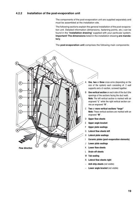
The components of the post-evaporation unit are supplied separately and<br />
must be assembled at the installation site.<br />
The following sections explain the general installation of the post-evaporation<br />
unit. Detailed information (dimensions, fastening points, etc.) can be<br />
found in the “installation drawing” supplied with your particular system.<br />
Important! The dimensions listed in the installation drawing are mandatory.<br />
The post-evaporation unit comprises the following main components:<br />
A<br />
A One, two or three cross arms (depending on the<br />
size of the system) each consisting of: 2 wall<br />
supports and a U-section, screwed together.<br />
B One vertical section on each side of the duct (the<br />
openings of the sections facing the duct wall).<br />
Note: The left vertical section is marked with an<br />
engraved “L” while the right vertical section carries<br />
an engraved “R”.<br />
C Two or more vertical sections “large”<br />
Note: These vertical sections are marked with an<br />
engraved “M”.<br />
D Upper flow sheets<br />
E Upper angle bracket<br />
F Upper plate sealings<br />
G Lateral flow sheets left<br />
H Lateral plate sealings<br />
I Ceramic plates (post-evaporation elements)<br />
J Lower plate sealings<br />
K Lower flow sheets<br />
L Drain-off sheets<br />
M Tub sealing<br />
N Lateral flow sheets right<br />
– Anti-drip sheets (not visible)<br />
– Lower angle bracket (not visible)<br />
19