Condair Dual 2 manual.pdf
Condair Dual 2 manual.pdf
Condair Dual 2 manual.pdf
- TAGS
- condair
- dual
- biossol.gr

Create successful ePaper yourself
Turn your PDF publications into a flip-book with our unique Google optimized e-Paper software.
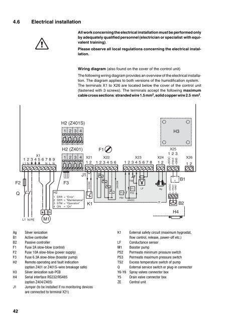
4.6 Electrical installation<br />
F2<br />
Q<br />
Ag Silver ionization<br />
B1 Active controller<br />
B2 Passive controller<br />
F1 Fuse 2A slow-blow (control)<br />
F2 Fuse 10A slow-blow (power supply)<br />
F3 Fuse 6.3A slow-blow (booster pump)<br />
H2 Remote operating and fault indication<br />
(option Z401 or Z401S–wire breakage safe)<br />
H3 Silver ionization sub-PCB<br />
H4 Serial interface RS232/RS485<br />
(option Z404/Z405)<br />
J1 Jumper (to be installed if no monitoring devices<br />
are connected to terminal X21)<br />
42<br />
All work concerning the electrical installation must be performed only<br />
by adequately qualified personnel (electrician or specialist with equivalent<br />
training).<br />
Please observe all local regulations concerning the electrical installation.<br />
Wiring diagram (also found on the cover of the control unit)<br />
The following wiring diagram provides an overview of the electrical installation.<br />
The diagram applies to both versions of the humidification system.<br />
The terminals X1 to X26 are located below the cover of the control unit<br />
(fastened with 3 screws). The terminals accept the following maximum<br />
cable cross sections: stranded wire 1.5 mm2 , solid copper wire 2.5 mm2 .<br />
X1<br />
1 2 3 4 X21 X22<br />
X23<br />
123456789<br />
L1 N N L N 12 123456 12345678<br />
L1 NPE<br />
L1 N<br />
M1<br />
H2 (Z401S)<br />
1<br />
F3<br />
2<br />
3<br />
4<br />
H2 (Z401)<br />
J1<br />
H2<br />
1 ERR = “Error”<br />
2 SER = “Maintenance”<br />
3 STM = “Operation”<br />
4 ON = “On”<br />
24VSIK<br />
K1<br />
F1<br />
Y5<br />
Y6<br />
Y7<br />
Y8<br />
24VSIK<br />
P<<br />
PS2<br />
TS2<br />
P><br />
PS3<br />
24VDC<br />
LF<br />
X25<br />
123<br />
X24<br />
X26<br />
12 12<br />
K1 External safety circuit (maximum hygrostat,<br />
flow control, release, power-off etc.)<br />
LF Conductance sensor<br />
M1 Booster pump<br />
PS2 Permeate minimum pressure switch<br />
PS3 Permeate maximum pressure switch<br />
TS2 Excess temperature switch of pump<br />
Q External service switch or plug-in connector<br />
Y6-Y8 Spray valves connector box<br />
Y5 Drain valve connector box<br />
ZE Central unit<br />
ZE<br />
Ag<br />
H3<br />
+9VDC<br />
+Input<br />
–GND<br />
+ -<br />
Y<br />
+9VDC<br />
+Input<br />
–GND<br />
1 2 3<br />
H4<br />
B1<br />
B2