1 Product information 2 Recommendations 3 Product data Page ............. 3 Tapered seating Page ............. 37 and the nut screwed on. By turning the nut through the recommended angle α the bearing will be pressed up on the tapered seating. As the bearing has a tendency to skew when being pressed into place it is advisable to reposition the hook spanner in a slot at 180° to that used for tightening and then applying a light hammer blow to the hook spanner. The bearing will straighten up on its seating. Finally the residual clearance of the bearing should be checked. In all cases, before mounting, the rust inhibiting oil should be wiped from the bore and outside diameter of new <strong>bearings</strong> and sleeves. The shaft seating and outside diameter of the sleeve should then be lightly oiled with thin oil. The SKF Drive-up Method The SKF Drive-up Method is based on measuring axial displacement of the bearing inner ring on its tapered seating from a reliably determined starting position. The SKF Drive-up Method (➔ fig 5 ) requires the use of an HMV .. E hydraulic nut, that can accommodate a dial gauge. A pressure gauge, appropriate to the mounting conditions, mounted on a suitably sized hand pump, allows accurate pressure measurement to determine the starting position. The tools required are shown in fig 6 . Guideline values for • the requisite oil pressure and • the axial displacement for the individual <strong>bearings</strong> are provided in table 3 on page 30. Bearing bore Reduction of Axial drive-up s 1) Permissible residual diameter radial internal Taper Taper radial clearance 2) d clearance 1:12 1:30 after mounting <strong>bearings</strong> with initial clearance over incl. min max min max min max Normal C3 C4 mm mm mm mm Table 24 30 0,012 0,018 0,25 0,34 0,64 0,85 0,025 0,033 0,047 30 40 0,015 0,024 0,30 0,42 0,74 1,06 0,031 0,038 0,056 40 50 0,020 0,030 0,37 0,51 0,92 1,27 0,033 0,043 0,063 50 65 0,025 0,039 0,44 0,64 1,09 1,59 0,038 0,049 0,074 65 80 0,033 0,048 0,54 0,76 1,36 1,91 0,041 0,055 0,088 80 100 0,040 0,060 0,65 0,93 1,62 2,33 0,056 0,072 0,112 100 120 0,050 0,072 0,79 1,10 1,98 2,75 0,065 0,083 0,129 120 140 0,060 0,084 0,93 1,27 2,33 3,18 0,075 0,106 0,147 140 160 0,070 0,096 1,07 1,44 2,68 3,60 0,085 0,126 0,173 160 180 0,080 0,108 1,21 1,61 3,04 4,02 0,093 0,140 0,193 180 200 0,090 0,120 1,36 1,78 3,39 4,45 0,103 0,150 0,209 200 225 0,100 0,135 1,50 1,99 3,74 4,98 0,113 0,163 0,228 225 250 0,113 0,150 1,67 2,20 4,18 5,51 0,123 0,175 0,251 250 280 0,125 0,168 1,85 2,46 4,62 6,14 0,133 0,186 0,276 280 315 0,140 0,189 2,06 2,75 5,15 6,88 0,143 0,198 0,292 315 355 0,158 0,213 2,31 3,09 5,77 7,73 0,161 0,226 0,329 355 400 0,178 0,240 2,59 3,47 6,48 8,68 0,173 0,251 0,358 400 450 0,200 0,270 2,91 3,90 7,27 9,74 0,183 0,275 0,383 450 500 0,225 0,300 3,26 4,32 8,15 10,80 0,210 0,295 0,433 500 560 0,250 0,336 3,61 4,83 9,04 12,07 0,225 0,327 0,467 560 630 0,280 0,378 4,04 5,42 10,09 13,55 0,250 0,364 0,508 s 2 630 710 0,315 0,426 4,53 6,10 11,33 15,25 0,275 0,386 0,560 710 800 0,355 0,480 5,10 6,86 12,74 17,15 0,319 0,430 0,620 800 900 0,400 0,540 5,73 7,71 14,33 19,27 0,335 0,465 0,675 900 1 000 0,450 0,600 6,44 8,56 16,09 21,39 0,364 0,490 0,740 1 000 1 120 0,500 0,672 7,14 9,57 17,86 23,93 0,395 0,543 0,823 1 120 1 250 0,560 0,750 7,99 10,67 19,98 26,68 0,414 0,595 0,885 Guideline values for clearance reduction and axial drive-up 1) Only valid for solid steel shafts 2) The residual clearance must be measured when the initial radial internal clearance (before mounting) lies in the lower half of the clearance range and if large temperature differences between inner and outer rings are to be expected in operation; the residual clearance should not be less than the minimum values quoted here. When measuring clearance care must be taken to see that both bearing rings and the <strong>roller</strong> complement are centrically arranged with respect to each other 28
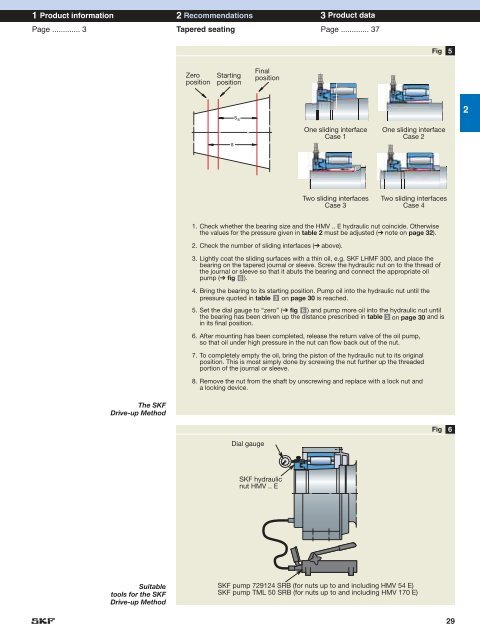
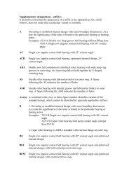
1 Product information 2 Recommendations 3 Product data Page ............. 3 Tapered seating Page ............. 37 Fig 5 Zero position Starting position Final position s ss One sliding interface Case 1 One sliding interface Case 2 2 Two sliding interfaces Case 3 Two sliding interfaces Case 4 1. Check whether the bearing size and the HMV .. E hydraulic nut coincide. Otherwise the values for the pressure given in table 2 must be adjusted (➔ note on page 32). 2. Check the number of sliding interfaces (➔ above). 3. Lightly coat the sliding surfaces with a thin oil, e.g. SKF LHMF 300, and place the bearing on the tapered journal or sleeve. Screw the hydraulic nut on to the thread of the journal or sleeve so that it abuts the bearing and connect the appropriate oil pump (➔ fig 6 ). 4. Bring the bearing to its starting position. Pump oil into the hydraulic nut until the pressure quoted in table 3 on page 30 is reached. 5. Set the dial gauge to “zero” (➔ fig 6 ) and pump more oil into the hydraulic nut until the bearing has been driven up the distance prescribed in table 3 on page 30 and is in its final position. 6. After mounting has been completed, release the return valve of the oil pump, so that oil under high pressure in the nut can flow back out of the nut. 7. To completely empty the oil, bring the piston of the hydraulic nut to its original position. This is most simply done by screwing the nut further up the threaded portion of the journal or sleeve. 8. Remove the nut from the shaft by unscrewing and replace with a lock nut and a locking device. The SKF Drive-up Method Fig 6 Dial gauge SKF hydraulic nut HMV .. E Suitable tools for the SKF Drive-up Method SKF pump 729124 SRB (for nuts up to and including HMV 54 E) SKF pump TML 50 SRB (for nuts up to and including HMV 170 E) 29