CARB® toroidal roller bearings â a revolutionary ... - Acorn Bearings
CARB® toroidal roller bearings â a revolutionary ... - Acorn Bearings
CARB® toroidal roller bearings â a revolutionary ... - Acorn Bearings

Create successful ePaper yourself
Turn your PDF publications into a flip-book with our unique Google optimized e-Paper software.
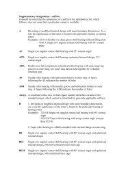
1 Product information 2 Recommendations 3 Product data<br />
Page ............. 3 Page ............. 12 Bearing data<br />
Axial displacement<br />
CARB <strong>toroidal</strong> <strong>roller</strong> <strong>bearings</strong> can<br />
accomodate changes in shaft length<br />
within certain limits. The guideline values<br />
for axial displacement given in the<br />
product tables are valid provided there is<br />
• a sufficiently large operational radial<br />
clearance in the bearing, and that<br />
• the rings are not misaligned.<br />
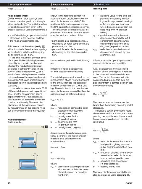
This means that the <strong>roller</strong>s (➔ fig 4 )<br />
will not protrude from the bearing rings<br />
(a) or interfere with the retaining ring<br />
(b) or with the seal, if any.<br />
If the axial movement exceeds 50 %<br />
of the permissible axial displacement<br />
capability s 1 , it should be checked,<br />
whether the residual radial internal<br />
clearance is sufficiently large. The reduction<br />
of radial clearance C red as a<br />
result of an axial displacement can be<br />
calculated using the equation shown in<br />
the section “Influence of radial operating<br />
clearance on the axial displacement<br />
capability”.<br />
If the axial movement exceeds 50 %<br />
of the axial displacement capability s 1<br />
or s 2 , and the misalignment attains<br />
approximately 0,5°, the actual axial<br />
displacement of the <strong>roller</strong>s should be<br />
checked additionally. The axial displacement<br />
of the <strong>roller</strong>s s mis caused<br />
by misalignment of the bearing rings<br />
can be calculated using the equation<br />
Axial displacement<br />
limits s 1 and s 2<br />
a<br />
b<br />
s 1<br />
s 2<br />
Fig<br />
4<br />
shown in the following section “Influence<br />
of <strong>roller</strong> displacement on the<br />
axial displacement capability”. For<br />
additional information please contact<br />
the SKF application engineering service.<br />
The maximum permissible axial displacement<br />
is obtained from the smaller<br />
of the minimum values of the<br />
• permissible axial displacement s lim<br />
depending on <strong>roller</strong> complement displacement,<br />
and the<br />
• permissible axial displacement s cle<br />
depending on the clearance reduction,<br />
calculated as explained in the following<br />
part.<br />
Influence of <strong>roller</strong> displacement<br />
on axial displacement capability<br />
The axial displacement, as well as the<br />
misalignment of one ring with respect<br />
to the other, changes the position of<br />
the <strong>roller</strong> complement in CARB bearing.<br />
The reduction in the permissible<br />
axial displacement caused by the misalignment<br />
can be estimated using<br />
s mis = k 1 B α<br />
where<br />
s mis = reduction in permissible axial<br />
displacement caused by<br />
misalignment, mm<br />
k 1 = misalignment factor<br />
(➔ product tables)<br />
B = bearing width, mm<br />
(➔ product tables)<br />
α = misalignment, degrees<br />
Assuming a sufficiently large operational<br />
clearance, the maximum permissible<br />
axial displacement is<br />
obtained from<br />
s lim = s 1 – s mis<br />
or<br />
s lim = s 2 – s mis<br />
where<br />
s lim = permissible axial displacement<br />
with respect to the <strong>roller</strong> complement<br />
caused by misalignment,<br />
mm<br />
s 1<br />
s 2<br />
= guideline value for the axial displacement<br />
capability in <strong>bearings</strong><br />
with cage, sealed <strong>bearings</strong><br />
or full complement <strong>bearings</strong><br />
when displacing away from the<br />
snap ring, mm (➔ product<br />
tables)<br />
= guideline value for the axial<br />
displacement capability in full<br />
complement <strong>bearings</strong> when<br />
displacing towards the snap<br />
ring, mm (➔ product tables)<br />
s mis = reduction in permissible axial<br />
displacement caused by misalignment,<br />
mm<br />
Influence of radial operating clearance<br />
on axial displacement capability<br />
Axial displacement from a centred<br />
position of one bearing ring in relation<br />
to the other reduces the radial clearance.<br />
The radial clearance reduction<br />
corresponding to a certain axial displacement<br />
from a centred position can<br />
be calculated using<br />
2<br />
k 2 s cle<br />
C red =<br />
B<br />
The clearance reduction cannot be<br />
larger than the bearing operating radial<br />
clearance.<br />
If instead a certain permissible radial<br />
clearance reduction is known, the corresponding<br />
permissible axial displacement<br />
from a centred position can be calculated<br />
using<br />
B C red<br />
s cle =<br />
k2<br />
where<br />
s cle = axial displacement from a centred<br />
position giving a certain<br />
radial clearance reduction C red ,<br />
mm<br />
C red = reduction of radial clearance as<br />
a result of an axial displacement<br />
from a centred position, mm<br />
k 2 = operating clearance factor<br />
(➔ product tables)<br />
B = bearing width, mm<br />
The axial displacement capability can<br />
also be obtained using diagram 1 ,<br />
40