MODEL: R3-NEIP1 - M-System
MODEL: R3-NEIP1 - M-System
MODEL: R3-NEIP1 - M-System

Create successful ePaper yourself
Turn your PDF publications into a flip-book with our unique Google optimized e-Paper software.
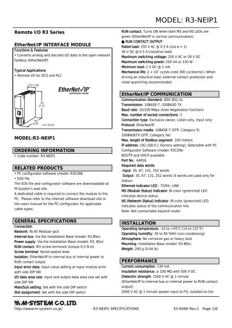
<strong>MODEL</strong>: <strong>R3</strong>-<strong>NEIP1</strong><br />
Remote I/O <strong>R3</strong> Series<br />
EtherNet/IP INTERFACE MODULE<br />
Functions & Features<br />
• Converts analog and discrete I/O data to the open network<br />
fieldbus (EtherNet/IP)<br />
Typical Applications<br />
• Remote I/O for DCS and PLC<br />
27.5 (1.08)<br />
109<br />
(4.29)<br />
130<br />
(5.12)<br />
mm (inch)<br />
<strong>MODEL</strong>:<strong>R3</strong>–<strong>NEIP1</strong><br />
ORDERING INFORMATION<br />
• Code number: <strong>R3</strong>-<strong>NEIP1</strong><br />
RELATED PRODUCTS<br />
• PC configurator software (model: <strong>R3</strong>CON)<br />
• EDS file<br />
The EDS file and configurator software are downloadable at<br />
M-<strong>System</strong>’s web site.<br />
A dedicated cable is required to connect the module to the<br />
PC. Please refer to the internet software download site or<br />
the users manual for the PC configurator for applicable<br />
cable types.<br />
GENERAL SPECIFICATIONS<br />
Connection<br />
Network: RJ-45 Modular Jack<br />
Internal bus: Via the Installation Base (model: <strong>R3</strong>-BSx)<br />
Power supply: Via the Installation Base (model: <strong>R3</strong>- BSx)<br />
RUN contact: M3 screw terminals (torque 0.5 N·m)<br />
Screw terminal: Nickel-plated steel<br />
Isolation: EtherNet/IP to internal bus or internal power to<br />
RUN contact output<br />
Input error data: Input value setting at input module error<br />
with side DIP SW<br />
I/O data area size: Input and output data area size set with<br />
side DIP SW<br />
Main/Sub setting: Set with the side DIP switch<br />
Slot assignment: Set with the side DIP switch<br />
RUN contact: Turns ON when both MS and NS LEDs are<br />
green (EtherNet/IP in normal communication).<br />
■ RUN CONTACT OUTPUT<br />
Rated load: 250 V AC @ 0.5 A (cos ø = 1)<br />
30 V DC @ 0.5 A (resistive load)<br />
Maximum switching voltage: 250 V AC or 30 V DC<br />
Maximum switching power: 250 VA or 150 W<br />
Minimum load: 1 V DC @ 1 mA<br />
Mechanical life: 2 × 10 7 cycles (rate 300 cycles/min.) When<br />
driving an inductive load, external contact protection and<br />
noise quenching recommended.<br />
EtherNet/IP COMMUNICATION<br />
Communication Standard: IEEE 802.3u<br />
Transmission: 10BASE-T, 100BASE-TX<br />
Baud rate: 10/100 Mbps (Auto Negotiation function)<br />
Max. number of socket connections: 3<br />
Connection type: Exclusive owner, Listen only, Input only<br />
Protocol: EtherNet/IP<br />
Transmission media: 10BASE-T (STP, Category 5)<br />
100BASETX (STP, Category 5e)<br />
Max. length of fieldbus segment: 100 meters<br />
IP address: 192.168.0.1 (factory setting); Selectable with PC<br />
Configurator Software (model: <strong>R3</strong>CON)<br />
BOOTP and DHCP available<br />
Port No.: 44818<br />
Required data words:<br />
Input: 35, 67, 131, 252 words<br />
Output: 35, 67, 131, 252 words (3 words are used only for<br />
status)<br />
Ethernet indicator LED: TX/RX, LINK<br />
MS (Module Status) indicator: Bi-color (green/red) LED<br />
indicates device status.<br />
NS (Network Status) indicator: Bi-color (green/red) LED<br />
indicates status of the communication link.<br />
Note: Not connectable beyond router.<br />
INSTALLATION<br />
Operating temperature: -10 to +55°C (14 to 131°F)<br />
Operating humidity: 30 to 90 %RH (non-condensing)<br />
Atmosphere: No corrosive gas or heavy dust<br />
Mounting: Installation Base (model: <strong>R3</strong>-BSx)<br />
Weight: 200 g (0.44 lb)<br />
PERFORMANCE<br />
Current consumption: 130 mA<br />
Insulation resistance: ≥ 100 MΩ with 500 V DC<br />
Dielectric strength: 1500 V AC @ 1 minute<br />
(EtherNet/IP to internal bus or internal power to RUN contact<br />
output)<br />
2000 V AC @ 1 minute (power input to FG; isolated on the<br />
http://www.m-system.co.jp/ <strong>R3</strong>-<strong>NEIP1</strong> SPECIFICATIONS ES-8466 Rev.1 Page 1/6
<strong>MODEL</strong>: <strong>R3</strong>-<strong>NEIP1</strong><br />
power supply module)<br />
EXTERNAL VIEW<br />
■ FRONT VIEW<br />
■ SIDE VIEW<br />
MS Indicator LED<br />
NS Indicator LED<br />
Functions<br />
Configuration Jack<br />
RJ-45 Modular Jack<br />
4<br />
5<br />
6<br />
1<br />
2<br />
3<br />
Ethernet Indicator<br />
LINK<br />
TX/RX<br />
4<br />
3<br />
2<br />
1<br />
SW3<br />
ON<br />
8<br />
7<br />
6<br />
5<br />
4<br />
3<br />
2<br />
1<br />
SW2<br />
ON<br />
8<br />
7<br />
6<br />
5<br />
4<br />
3<br />
2<br />
1<br />
SW1<br />
ON<br />
http://www.m-system.co.jp/ <strong>R3</strong>-<strong>NEIP1</strong> SPECIFICATIONS ES-8466 Rev.1 Page 2/6
<strong>MODEL</strong>: <strong>R3</strong>-<strong>NEIP1</strong><br />
TRANSMISSION DATA DESCRIPTIONS<br />
The DIP SW located at the side of the module specifies each I/O module's data allocation (occupied data area and size of the I/O data area).<br />
For example, when the data areas are assigned as shown below:<br />
Module 1 4<br />
Module 2 4<br />
Module 3 4<br />
Module 4 1<br />
Module 5 1<br />
Module 6 1<br />
Module 7 1<br />
I/O data area: 252 words each for input and output.<br />
Then the I/O data are assigned as in the figures below:<br />
■ OUTPUT DATA<br />
The figure below shows the allocation of the data sent from<br />
the network module to the master.<br />
■ INPUT DATA<br />
The figure below shows the allocation of the data sent from<br />
the master to the network module.<br />
Begin<br />
Address<br />
+0<br />
15<br />
0<br />
Begin<br />
Address<br />
+0<br />
15<br />
0<br />
+2<br />
Module 1<br />
+2<br />
Module 1<br />
+4<br />
+4<br />
+6<br />
Module 2<br />
+6<br />
Module 2<br />
+8<br />
+8<br />
+10<br />
Module 3<br />
+10<br />
Module 3<br />
+12<br />
Module 4<br />
+12<br />
Module 4<br />
Module 5<br />
Module 5<br />
+14<br />
Module 6<br />
+14<br />
Module 6<br />
Module 7<br />
Module 7<br />
+16 +16<br />
:<br />
:<br />
:<br />
:<br />
+249<br />
+251<br />
Module Status<br />
Error Status<br />
Data Error Status<br />
+249<br />
+251<br />
The area enclosed with bold line is assigned for I/O data<br />
Module Status, Error Status and Data Error Status are assigned to the last three words of the output data respectively.<br />
Each module can handle either input or output data.<br />
•Module Status indicates whether individual I/O module are mounted or not. The bit corresponding to the mounted slots<br />
turns to "1," and the unmounted slots to "0."<br />
•Error Status indicates error status for each module as described below. The bit corresponding to such modules turns to "1."<br />
<strong>R3</strong>-TSx, <strong>R3</strong>-RSx, <strong>R3</strong>-US4 (T/C or RTD input): Input burnout<br />
<strong>R3</strong>-DA16A: Power input in error or disconnected<br />
<strong>R3</strong>-YSx: Output current error (e.g. load unconnected)<br />
•Data Error Status indicates overrange (<strong>R3</strong>-US4: out of -10% to +110%; the other types: out of -15% to +115%) status for each<br />
module. The bit corresponding to such modules turns to "1."<br />
http://www.m-system.co.jp/ <strong>R3</strong>-<strong>NEIP1</strong> SPECIFICATIONS ES-8466 Rev.1 Page 3/6
<strong>MODEL</strong>: <strong>R3</strong>-<strong>NEIP1</strong><br />
I/O DATA DESCRIPTIONS<br />
■ MODULE STATUS, ERROR STATUS, DATA ERROR STATUS<br />
Shows each module's availability and error status.<br />
15<br />
0<br />
Module 1<br />
Module 2<br />
Module 3<br />
:<br />
Module 16<br />
■ ANALOG DATA (models: <strong>R3</strong>-SV4, YV4, DS4, YS4, US4, etc.)<br />
16-bit binary data.<br />
Basically, 0 to 100% of the selected I/O range is converted into 0 to 10000 (binary). Negative percentage is represented in 2's<br />
complements.<br />
15<br />
0<br />
■ TEMPERATURE DATA (models: <strong>R3</strong>-RS4, TS4, US4, etc.)<br />
16-bit binary data.<br />
With °C temperature unit, raw data is multiplied by 10. For example, 25.5°C is converted into 255.<br />
With °F temperature unit, the integer section of raw data is directly converted into the data.<br />
For example, 135.4°F is converted into 135.<br />
Minus temperature is converted into negative values, represented in 2’s complements.<br />
15<br />
0<br />
■ ACCUMULATED COUNT DATA (32-bit data, models: <strong>R3</strong>-PA2, PA4A, WT1, WT4, etc.)<br />
32-bit binary data is used for accumulated counts and encoder positions.<br />
Lower 16 bits are allocated from the lowest address to higher ones, higher 16 bits in turn.<br />
32-bit data cannot be accessed using floating addresses.<br />
15<br />
+0 Lower 16 bits<br />
0<br />
15<br />
+1 Higher 16 bits<br />
0<br />
■ BCD DATA (32-bit data, models: <strong>R3</strong>-BA32A, BC32A, etc.)<br />
32-bit binary data is used for BCD.<br />
Lower 16 bits are allocated from the lowest address to higher ones, higher 16 bits in turn.<br />
32-bit data cannot be accessed using floating addresses.<br />
15<br />
+0 Lower 16 bits<br />
0<br />
15<br />
+1 Higher 16 bits<br />
0<br />
http://www.m-system.co.jp/ <strong>R3</strong>-<strong>NEIP1</strong> SPECIFICATIONS ES-8466 Rev.1 Page 4/6
<strong>MODEL</strong>: <strong>R3</strong>-<strong>NEIP1</strong><br />
■ 16-POINT DISCRETE DATA (models: <strong>R3</strong>-DA16, DC16, etc.)<br />
15<br />
0<br />
0 : OFF<br />
1 : ON<br />
Input 1 (Output 1)<br />
Input 2 (Output 2)<br />
Input 3 (Output 3)<br />
: :<br />
Input 16 (Output 16)<br />
EXTERNAL DIMENSIONS & TERMINAL ASSIGNMENTS unit: mm (inch)<br />
27.5 (1.08) 109 (4.29)<br />
POSITIONING<br />
GUIDE<br />
130 (5.12)<br />
6–M3<br />
SCREW<br />
4<br />
5<br />
6<br />
1<br />
2<br />
3<br />
6.2<br />
(.24)<br />
TERMINAL<br />
COVER<br />
SCHEMATIC CIRCUITRY & CONNECTION DIAGRAM<br />
EtherNet/IP RJ-45 MODULAR JACK<br />
RUN + 1<br />
RUN CONTACT OUTPUT<br />
RUN – 4<br />
CONFIGURATION JACK JACK<br />
Isolation<br />
LED<br />
Control<br />
Circuit<br />
ETHERNET<br />
LED<br />
DIP SW<br />
Communication<br />
Circuit<br />
BUS CONNECTOR<br />
INTERNAL<br />
COMM. BUS<br />
INTERNAL POWER<br />
2<br />
3<br />
5<br />
http://www.m-system.co.jp/ <strong>R3</strong>-<strong>NEIP1</strong> SPECIFICATIONS ES-8466 Rev.1 Page 5/6
<strong>MODEL</strong>: <strong>R3</strong>-<strong>NEIP1</strong><br />
SYSTEM CONFIGURATION EXAMPLES<br />
EtherNet/IP<br />
Master Station<br />
Ethernet<br />
Hub<br />
Ethernet<br />
Ethernet<br />
EtherNet/IP Interface Module<br />
model: <strong>R3</strong>-<strong>NEIP1</strong><br />
EtherNet/IP Interface Module<br />
model: <strong>R3</strong>-<strong>NEIP1</strong><br />
Specifications are subject to change without notice.<br />
http://www.m-system.co.jp/ <strong>R3</strong>-<strong>NEIP1</strong> SPECIFICATIONS ES-8466 Rev.1 Page 6/6