Conductivity Switch Series - Hawk Measurement Systems!
Conductivity Switch Series - Hawk Measurement Systems!
Conductivity Switch Series - Hawk Measurement Systems!

Create successful ePaper yourself
Turn your PDF publications into a flip-book with our unique Google optimized e-Paper software.
A higher level of performance<br />
Data Sheet<br />
<strong>Conductivity</strong> <strong>Switch</strong> <strong>Series</strong><br />
- A level switch for liquids and slurrys -<br />
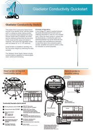
The Gladiator <strong>Conductivity</strong> <strong>Switch</strong> is a third generation, stateof-the-art<br />
level probe, designed to operate in tough industrial<br />
environments.<br />
Principle of Operations<br />
A low voltage AC signal is applied between the probe electrode<br />
and the tank wall or reference electrode in the case of a<br />
non-metallic tank. When the liquid comes into contact with<br />
the electrode tip, a conductive path is established between the<br />
sense electrode and the metallic tank wall/reference electrode.<br />
Current flow due to the conductive path is sensed, amplified<br />
and used to switch a relay for indication or control purposes.<br />
Typical Uses<br />
Fail-safe high-level/low-level alarm<br />
High-level alarm<br />
Low-level alarm<br />
High and low-level<br />
Interface Detection<br />
Pump control<br />
Function<br />
Point level switch for conductive liquids. Metallic tanks may<br />
use either single or dual probe versions whilst non metallic<br />
tanks must used a dual probe version.<br />
Primary Areas of Application<br />
- Brewing<br />
- Paint<br />
- Chemical<br />
- Paper<br />
- Dairy<br />
- Pharmaceutical<br />
- Edible Oil - Power Generation<br />
- Fertilizer<br />
- Refining<br />
- Food & Beverage - Semiconductor<br />
- Glass<br />
- Sugar<br />
- Mining & Metals - Textile<br />
- Oil & Gas - Water & Wastewater<br />
- Packaging<br />
Features:<br />
•<br />
•<br />
•<br />
•<br />
•<br />
•<br />
•<br />
•<br />
•<br />
•<br />
•<br />
•<br />
No moving parts - low maintenance<br />
Low voltage on probe for operational safety<br />
Simple ‘1-minute’ setup<br />
Remote sensor or Smart ‘all in one’ types<br />
Relays outputs: Smart probe (1) Remote (2)<br />
Remote test function<br />
Adjustable ON and OFF delays (0-20 sec)<br />
Smart communication options: Gos<strong>Hawk</strong>,<br />
Modbus, HART, Profibus DP, DeviceNet<br />
Remote GSM Connection option<br />
Remote amplifier to probe separation up to<br />
500 m (1640 ft)<br />
Bright visual status indication on probe<br />
Independent housing alignment after<br />
mounting thread locked
Typical Applications<br />
Sump pump control<br />
Non-metallic tank<br />
High level switch in water tank<br />
Metallic tank<br />
* mounting must be electrically<br />
connected to tank wall.<br />
Gladiator - <strong>Conductivity</strong> <strong>Switch</strong> <strong>Series</strong>
Dimensions<br />
Single Probe<br />
Two Probes<br />
single switch point<br />
Two Probes<br />
dual switch points<br />
Window for<br />
viewing status<br />
LEDs<br />
85mm (3.3”)<br />
Window for<br />
viewing status<br />
LEDs<br />
85mm (3.3”)<br />
Window for<br />
viewing status<br />
LEDs<br />
85mm (3.3”)<br />
M20 cable gland<br />
or 3/4” NPT adaptor<br />
on smart type.<br />
50mm (2”)<br />
90mm (3.5”)<br />
2 x M20<br />
cable glands<br />
or 3/4” NPT adaptors<br />
on remote type.<br />
10mm (0.3”)<br />
Mounting<br />
thread<br />
Bare probe<br />
50mm (2”)<br />
50mm (2”)<br />
90mm (3.5”)<br />
50mm (2”)<br />
90mm (3.5”)<br />
teflon isolated probe<br />
for build-up protection<br />
probe length = L1<br />
Optional<br />
Flange<br />
teflon isolated probe<br />
for build-up protection<br />
Mounting<br />
thread, 1.5” NPT<br />
or BSP only<br />
8mm (0.3”)<br />
Bare probe<br />
probe length = L1 = L2<br />
50mm (2”)<br />
probe length L1<br />
teflon isolated probe<br />
for build-up protection<br />
Mounting<br />
thread, 1.5” NPT<br />
or BSP only<br />
probe length L2<br />
5mm (0.2”)<br />
Optional Flange Dimensions - 50mm (2”)<br />
Standard probe lengths (L1 or L2):<br />
• 30 cm (11.8”)<br />
• 50 cm (19.7”)<br />
• 100 cm (39.4”)<br />
C<br />
A B<br />
ANSI (Class150)<br />
A<br />
120.7 4.75”<br />
B<br />
152.4 6”<br />
C<br />
19.1 0.75”<br />
DIN (PN40) 125 4.9” 165 6.5” 18 0.7”<br />
JIS (10K) 120 4.7” 155 6.1” 19 0.75”<br />
Remote Amplifier Enclosure<br />
192.5 mm (7.6”)<br />
174 mm (6.9”)<br />
111.5 mm (4.4”)<br />
78 mm (3.1”)<br />
14 mm (0.6”)<br />
30.7 mm (1.2”)<br />
7.5 mm (0.3”)<br />
192.5 mm (7.6”)<br />
147 mm (5.8”)<br />
108 mm (4.3”)<br />
190 mm (7.5”)<br />
107 mm (4.2”)<br />
190 mm (7.5”)<br />
167.5 mm (6.6”)<br />
141.5 mm (5.6”)<br />
131.5 mm (5.2”)<br />
182.5 mm (7.2”)<br />
50 mm (2”)<br />
74 mm (2.9”)<br />
4 mm (0.2”)<br />
147 mm (5.8”)<br />
158 mm (6.2”)<br />
182.5 mm (7.2”)<br />
<br />
Gladiator - <strong>Conductivity</strong> <strong>Switch</strong> <strong>Series</strong>
Communication Network Overview<br />
Multidrop Connections<br />
Gladiator<br />
Admittance<br />
<strong>Switch</strong><br />
Gladiator<br />
Admittance<br />
<strong>Switch</strong><br />
Gladiator<br />
Admittance<br />
<strong>Switch</strong><br />
Gladiator<br />
Admittance<br />
<strong>Switch</strong><br />
Sultan Acoustic<br />
Wave Transmitter<br />
Slurries<br />
Sultan Acoustic<br />
Wave Transmitter<br />
Flotation Cells<br />
Sultan Acoustic Wave Transmitter<br />
Silo, bin levels, coal, plastic powder,<br />
woodchip, sawdust, cement,<br />
clinker, iron ore, lime etc.<br />
Gladiator<br />
<strong>Conductivity</strong><br />
<strong>Switch</strong><br />
GLadiator<br />
Microwave<br />
Low Level<br />
Gladiator<br />
Microwave<br />
Low Level<br />
SULTAN 234<br />
Sultan, Gladiator & Guided Radar<br />
Farm Tanks, Grain Terminals<br />
Gladiator<br />
<strong>Conductivity</strong><br />
<strong>Switch</strong><br />
Orca Sonar Interface<br />
Thickener, CCD<br />
SULTAN 234<br />
Sultan Acoustic<br />
Wave <strong>Switch</strong><br />
Blocked Chute Detection<br />
Orca Sonar Interface<br />
Clarifier<br />
GSM Network<br />
or<br />
CDMA Network<br />
Sultan Master/Slave Positioning System<br />
Sultan Acoustic Wave Transmitter<br />
Stockpiles, Stackers,<br />
Reclaimers<br />
GSM or CDMA Network<br />
• Typically up to 31 transmitters or switches per string.<br />
• Maximum 250 transmitters or switches.<br />
• Using GSM/CDMA network, transmitters and switches can be<br />
monitored, calibrated remotely.<br />
• Alarm status, diagnostics can be monitored.<br />
• Support from factory engineering for customer application problems.<br />
Laptop or PC Communications<br />
or PLC / DCS with<br />
MODBUS RTU Port<br />
Gos<strong>Hawk</strong> Software for<br />
inventory monitoring on PC<br />
(Limited Modbus query rate for <strong>Switch</strong>es only)<br />
Gladiator - <strong>Conductivity</strong> <strong>Switch</strong> <strong>Series</strong>
Wiring<br />
Smart Probe Wiring<br />
Remove Plug-In<br />
terminal block for<br />
easier wiring.<br />
SENSITIVITY<br />
HI FSH CAL TEST<br />
DELAY<br />
1 2 3 4 5 6 7 8 9 10<br />
!<br />
The AC earth/ground<br />
cable must be connected<br />
to the ground screw<br />
inside the housing when<br />
using AC power.<br />
Hole for securing of<br />
optional identification tag<br />
If only one cable is used for both<br />
power and output signal, then the<br />
second entry port must be<br />
plugged or blinded. Every Smart<br />
unit is supplied with two M20<br />
glands (or 3/4”NPT adaptors)<br />
mounted on the unit and one<br />
blind plug loose.<br />
1. NC<br />
Ground the housing to<br />
vessel, if vessel is metallic.<br />
Ground the housing to<br />
plant ground, if vessel is<br />
non-metallic.<br />
RELAY<br />
2. COM<br />
M4 grounding screw<br />
GLADIATOR SMART PROBE TERMINAL LAYOUT<br />
3. NO<br />
4. Test<br />
COMMS DC-IN AC-IN<br />
A<br />
5.<br />
B<br />
6.<br />
RS 485<br />
<br />
7.<br />
7-30Vdc<br />
-<br />
8.<br />
N<br />
9.<br />
L1<br />
10.<br />
80-265 Vac<br />
<br />
Gladiator - <strong>Conductivity</strong> <strong>Switch</strong> <strong>Series</strong>
Wiring<br />
Remote Amplifier Wiring Diagram<br />
Remove Plug-In<br />
terminal block for<br />
easier wiring.<br />
GLADIATOR REMOTE PROBE TERMINAL LAYOUT<br />
1 2 3 4 5 6 7 8 9 10<br />
1. 2. 3. 4. 5. 6. 7. 8. 9. 10.<br />
WHITE<br />
BLUE<br />
RED<br />
BLACK<br />
Terminals 1, 2, 3, 4, 9, 10 not used.<br />
Hole for securing of<br />
optional identification tag<br />
GLADIATOR REMOTE AMPLIFIER TERMINAL LAYOUT<br />
M4 grounding screw<br />
NOT USED<br />
Test in<br />
RELAY 1<br />
NC<br />
COM<br />
NO<br />
RELAY 2<br />
(FAIL SAFE)<br />
NC<br />
COM<br />
NO<br />
Ground the housing to<br />
vessel, if vessel is metallic.<br />
Ground the housing to<br />
plant ground, if vessel is<br />
non-metallic.<br />
CURRENT<br />
SENSOR<br />
COMMS<br />
DC-IN<br />
AC-IN<br />
Is<br />
+ –<br />
RED<br />
BLACK<br />
BLUE<br />
WHITE<br />
NOT USED<br />
B<br />
A<br />
– +<br />
N<br />
L1<br />
24 VDC 80-265 VAC<br />
Cable type between Amplifier and Probe<br />
4 conductor shielded twisted pair instrument cable.<br />
Conductor size dependent on cable length.<br />
BELDEN 3084A, DEKORON or equivalent.<br />
Max: BELDEN 3084A = 500m (1640 ft)<br />
Max: DEKORON IED183AA002 = 350m (1150 ft)<br />
Gladiator - <strong>Conductivity</strong> <strong>Switch</strong> <strong>Series</strong>
Wiring<br />
Relay Functions<br />
Level <strong>Switch</strong><br />
Contact Action<br />
Single <strong>Switch</strong> Point<br />
Dual <strong>Switch</strong> Points<br />
FailSafe Low<br />
FSL<br />
Relay Action<br />
FailSafe High<br />
FSH (default)<br />
Relay - for Smart Probe Version<br />
(Set Relay Action selection<br />
switch)<br />
Relay 1 - for Remote Version<br />
(Set Relay Action parameter)<br />
State 1<br />
OR<br />
1 2 3<br />
NC COM NO<br />
1 2 3<br />
NC COM NO<br />
Relay Status<br />
Smart Probe<br />
terminal numbers<br />
Remote Amplifier<br />
terminal function<br />
labels<br />
LED Status<br />
RISING LEVEL<br />
RISING LEVEL<br />
State 2<br />
1 2 3<br />
1 2 3<br />
NC COM NO<br />
CONTACT LEVEL<br />
CONTACT LEVEL<br />
FALLING LEVEL<br />
State 1<br />
1 2 3<br />
NC COM NO<br />
1 2 3<br />
NC COM NO<br />
FALLING LEVEL<br />
POWER FAILURE<br />
1 2 3<br />
NC COM NO<br />
1 2 3<br />
NC COM NO<br />
Fail-Safe <strong>Switch</strong> Contact Action<br />
Relay 2 - Remote version only.<br />
For Smart Probes the Test terminal<br />
can act as a solid state output with a<br />
similar function.<br />
POWER FAILURE<br />
OR<br />
INTERNAL FAILURE<br />
NC COM NO NC COM NO<br />
SYSTEM OPERATING<br />
NORMALLY<br />
NC COM NO<br />
NC COM NO<br />
<br />
Gladiator - <strong>Conductivity</strong> <strong>Switch</strong> <strong>Series</strong>
Mounting Examples<br />
Mounting<br />
Probes can be mounted from above or from the side.<br />
Use a protection plate for side mounting where the probe may<br />
be subject to impact damage.<br />
Install the Probe far enough away from the vessel wall to<br />
prevent the probe from coming into contact with the wall, and<br />
prevent conductive build-up from bridging the probe to the wall<br />
over time.<br />
Incorrect<br />
2<br />
Possible conductive<br />
build-up<br />
Correct<br />
Correct<br />
Incorrect<br />
1<br />
1<br />
Incorrect<br />
If necessary, mount a<br />
protection plate to<br />
prevent direct impact.<br />
Possible<br />
product<br />
build-up<br />
Correct<br />
30-45º<br />
Correct<br />
Housing can be rotated<br />
within 200º after the<br />
mounting thread is<br />
tightened, to allow cable<br />
entries to face downwards<br />
or allow optimal cable<br />
clearance.<br />
Correct<br />
Incorrect 2<br />
Correct (non-preferred<br />
low level mounting)<br />
Gladiator - <strong>Conductivity</strong> <strong>Switch</strong> <strong>Series</strong>
Advanced Remote Communication<br />
GSM/CDMA Communication<br />
<strong>Hawk</strong>Link GSM/CDMA communication device allows any<br />
authorized computer with a standard modem and Gos<strong>Hawk</strong><br />
software to dial in and calibrate, test or check on the performance<br />
of the connected <strong>Hawk</strong> product. The <strong>Hawk</strong>Link device<br />
can be wired to the standard communication terminals of the<br />
<strong>Hawk</strong> products.<br />
Remote technical support and complete commissioning of<br />
equipment in applications via our GSM/CDMA module allows<br />
monitoring and adjustments of settings no matter what corner<br />
of the world.<br />
Remote connection worldwide!<br />
<br />
Gladiator - <strong>Conductivity</strong> <strong>Switch</strong> <strong>Series</strong>
Part Numbering<br />
Smart Probe Version<br />
CS3100 SMART Gladiator <strong>Conductivity</strong> <strong>Switch</strong><br />
Power Supply<br />
B 24 VDC standard (7-30VDC)<br />
U Universal AC power supply (80-260 VAC input) and 7-30VDC<br />
Output Options<br />
S <strong>Switch</strong>. 1 level relay, with Modbus<br />
Z Special Request<br />
Housing<br />
S Standard Powder Coated, Diecast with glass lid<br />
C Corrosion Resistant, Stainless Steel Housing<br />
Type of Electrodes<br />
S Single Point 1 Electrode Type for Metallic tanks<br />
D Dual Point 2 Electrode Type for Metallic tanks<br />
N Single Point 2 Electrode Type for Non-Metallic tanks (L1 must = L2)<br />
Mounting<br />
TN10 1” NPT Thread - Size only available for 1 electrode type<br />
TB10 1” BSP Thread - Size only available for 1 electrode type<br />
TN15 1.5” NPT Thread<br />
TB15 1.5” BSP Thread<br />
TZ Special Thread Request<br />
FA2 2” Flange ANSI (Class 150)<br />
FD2 2” Flange DN 50 PN 40<br />
FJ2 2” Flange JIS (10K)<br />
FZ Special Flange Request<br />
Approval Standard<br />
X Standard CE Approved<br />
A20 ATEX 20 (DC power only)<br />
A22 ATEX 22 (DC power only)<br />
L1. Probe Length (Active Probe)<br />
P30 30 cm (11.8”) rigid probe<br />
P50 50 cm (18.7”) rigid probe<br />
P100 100 cm (39.4”) rigid probe<br />
Z Special length<br />
L2. Probe Length (Reference Probe - equal to or longer than L1)<br />
X Not required for 1 electrode type<br />
P30 30 cm (11.8”) rigid probe<br />
P50 50 cm (19.7”) rigid probe<br />
P100 100 cm (39.3”) rigid probe<br />
Z Special length<br />
CS3100 B S S S TN10 X P30 X Single Point <strong>Switch</strong> - Metallic Tank<br />
CS3100 B S S D TN15 X P30 P50 Dual Point <strong>Switch</strong> - Metallic Tank<br />
CS3100 B S S N TN15 X P30 P30 Single Point <strong>Switch</strong> - Non-Metallic Tank<br />
Gladiator - <strong>Conductivity</strong> <strong>Switch</strong> <strong>Series</strong> 10
Part Numbering<br />
Remote Version<br />
Remote Amplifier<br />
GSA Gladiator Amplifier - Remote (compatible with all Gladiator products)<br />
Housing<br />
S Standard polycarbonate electronics housing<br />
Power Supply<br />
B 24 VDC standard (12-30VDC)<br />
C 48 VDC<br />
U Universal AC power supply (80-260 VAC input) and 7-30VDC<br />
Output Options<br />
S <strong>Switch</strong>. 1 level relay, 1 failsafe relay, with Modbus<br />
I HART Isolated. 1 level relay, 1 failsafe relay<br />
D Devicenet. 1 level relay, 1 failsafe relay<br />
P Profibus DP. 1 level relay, 1 failsafe relay<br />
Z Special Request<br />
GSA S C S<br />
Remote Probe<br />
CS3200 Remote Gladiator <strong>Conductivity</strong> Probe (must be connected to GSA transmitter)<br />
Housing<br />
S Standard Powder Coated, Diecast with glass lid<br />
C Corrosion Resistant, Stainless Steel Housing<br />
Type of Electrodes<br />
S Single Point 1 Electrode Type for Metallic tanks<br />
D Dual Point 2 Electrode Type for Metallic tanks<br />
N Single Point 2 Electrode Type for Non-Metallic tanks (L1 must = L2)<br />
Mounting<br />
TN10 1” NPT Thread - Size only available with 1 electrode type for metallic tanks<br />
TB10 1” BSP Thread - Size only available with 1 electrode type for metallic tanks<br />
TN15 1.5” NPT Thread<br />
TB15 1.5” BSP Thread<br />
TZ Special Thread Request<br />
FA2 2” Flange ANSI (Class 150)<br />
FD2 2” Flange DN 50 PN 40<br />
FJ2 2” Flange JIS (10K)<br />
FZ Special Flange Request<br />
Approval Standard<br />
X Standard CE Approved<br />
A20 ATEX 20 (DC power only)<br />
A22 ATEX 22 (DC power only)<br />
L1. Probe Length (Active Probe)<br />
P30 30 cm (11.8”) rigid probe<br />
P50 50 cm ( 19.7”) rigid probe<br />
P100 100 cm (39.4”) rigid probe<br />
Z Special length<br />
L2. Probe Length (Reference Probe - equal to or longer than L1)<br />
X Not required for 1 electrode type<br />
P30 30 cm (11.8”) rigid probe<br />
P50 50 cm (19.7”) rigid probe<br />
P100 100 cm (39.3”) rigid probe<br />
Z Special length<br />
CS3200 S S TN10 X P30 X Single Point <strong>Switch</strong> - Metallic Tank<br />
CS3200 S D TN15 X P30 P50 Dual Point <strong>Switch</strong> - Metallic Tank<br />
CS3200 S N TN15 X P30 P30 Single Point <strong>Switch</strong> - Non-Metallic Tank<br />
11<br />
Gladiator - <strong>Conductivity</strong> <strong>Switch</strong> <strong>Series</strong>
Specifications<br />
Operating Voltage<br />
• 7 - 30VDC (residual ripple no greater than 100mV)<br />
• 80 - 260VAC 50/60Hz<br />
Power Consumption<br />
•