e-Gladiator Microwave Switch Data Sheet - Hawk Measurement
e-Gladiator Microwave Switch Data Sheet - Hawk Measurement
e-Gladiator Microwave Switch Data Sheet - Hawk Measurement

You also want an ePaper? Increase the reach of your titles
YUMPU automatically turns print PDFs into web optimized ePapers that Google loves.
Overview<br />
<strong>Gladiator</strong> <strong>Microwave</strong> Smart <strong>Switch</strong> Series<br />
A Higher Level of Performance<br />
<strong>Data</strong> <strong>Sheet</strong><br />
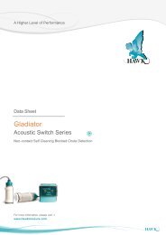
<strong>Gladiator</strong><br />
<strong>Microwave</strong> Smart <strong>Switch</strong> Series<br />
Beam Blockage Detection<br />
For more information, please visit ><br />
www.hawkmeasure.com
Overview<br />
<strong>Gladiator</strong> <strong>Microwave</strong> Smart <strong>Switch</strong> Series<br />
Overview<br />
Principle of Operation<br />
A beam of microwave energy passes from a sender to a separate receiver in bursts approximately 200 times per second. If the path<br />
between the sender and receiver is blocked by any object or material which absorbs or reflects microwave energy, the receiver<br />
will not be able to detect the signal. The presence or absence of the signal at the receiver is used to switch a relay for indication or<br />
control purposes.<br />
Typical Uses<br />
Primary Areas of Application<br />
• Blocked chute detection<br />
• Stacker / reclaimer protection<br />
• Shiploader protection<br />
• Nucleonic switch replacement<br />
• High level alarm / Low level alarm<br />
• Truck / machine detection.<br />
Function<br />
The <strong>Gladiator</strong> <strong>Microwave</strong> Smart <strong>Switch</strong> can be used for<br />
blockage detection, barrier detection, machine<br />
detection or protection and point level measurement, and<br />
detection of objects or material between two points.<br />
Note:<br />
• Asphalt<br />
• Brewing<br />
• Cement<br />
• Chemical<br />
• Dairy<br />
• Edible oil<br />
• Fertilizer<br />
• Food & Beverage<br />
• Glass<br />
• Mining & Metals<br />
• Oil & Gas<br />
• Packaging<br />
• Paint<br />
• Paper<br />
• Pharmaceutical<br />
• Plastics<br />
• Power Generation<br />
• Refining<br />
• Semiconductor<br />
• Sugar<br />
• Textile<br />
• Water & Wastewater.<br />
For wet, dusty environments where build up issues of wet high dielectric material is prevalent <strong>Microwave</strong> technology will have<br />
performance problems. HAWK recommends the <strong>Gladiator</strong> Acoustic <strong>Switch</strong> for these applications.<br />
Features<br />
• LCD setup / diagnostics on remote amplifier<br />
• Ranges up to 200 meters (656 ft)<br />
• Simple ‘1-minute’ setup<br />
• Remote sensor or Smart Integral ‘all in one’ types<br />
• Relay outputs: Smart Integral (1) Remote (2)<br />
• Remote test function<br />
• Adjustable ON and OFF delays (0-20 sec)<br />
• Remote 3G connection option<br />
• Remote amplifier to sensor separation up to 500 meters (1640 ft)<br />
• Bright visual status indication on sensors<br />
• Independent housing alignment after mounting sensor.<br />
2
CAL<br />
RUN<br />
CAL<br />
RUN<br />
Overview Typical Applications<br />
<strong>Gladiator</strong> <strong>Microwave</strong> Smart <strong>Switch</strong> Series<br />
Overview<br />
Cement Plants / Powders<br />
Solid Level - Cyclone Bin High / Low Level<br />
Coal Fired Power Station, Bulk Material Handling<br />
High / Low blocked chute detection<br />
For dual receiver wiring see user manual.<br />
Receiver<br />
Sender<br />
High<br />
Receiver<br />
Sender<br />
Low<br />
CAL<br />
RUN<br />
“Blocked Chute”<br />
Mount <strong>Microwave</strong> under<br />
pulley or out of main<br />
system flow<br />
3
Overview Dimensions<br />
<strong>Gladiator</strong> <strong>Microwave</strong> Smart <strong>Switch</strong> Series<br />
Overview<br />
Remote <strong>Microwave</strong> System<br />
Remote Amplifier<br />
111.5 mm (4.4”)<br />
192.5 mm (7.6”)<br />
174 mm (6.9”)<br />
78 mm (3.1”)<br />
14 mm (0.6”)<br />
30.7 mm (1.2”)<br />
7.5 mm (0.3”)<br />
192.5 mm (7.6”)<br />
147 mm (5.8”)<br />
108 mm (4.3”)<br />
190 mm (7.5”)<br />
107 mm (4.2”)<br />
190 mm (7.5”)<br />
167.5 mm (6.6”)<br />
141.5 mm (5.6”)<br />
131.5 mm (5.2”)<br />
16.2<br />
30.0<br />
33.0<br />
29.0<br />
29.0<br />
33.0<br />
20.2<br />
182.5 mm (7.2”)<br />
50 mm (2”)<br />
74 mm (2.9”)<br />
4 mm (0.2”)<br />
147 mm (5.8”)<br />
158 mm (6.2”)<br />
182.5 mm (7.2”)<br />
Remote Sender / Receiver<br />
Ø85 mm (3.3”)<br />
Ø85 mm (3.3”)<br />
Smart Integral <strong>Microwave</strong> System<br />
50 mm (2”)<br />
90 mm (3.5”)<br />
2 mm (0.078”)<br />
10 mm (0.4”)<br />
50 mm (2”)<br />
90 mm (3.5”)<br />
12 mm (0.5”)<br />
Ø85 mm (3.3”)<br />
50 mm (2”)<br />
90 mm (3.5”)<br />
2 mm (0.078”)<br />
10 mm (0.4”)<br />
Ø85 mm (3.3”)<br />
50 mm (2”)<br />
90 mm (3.5”)<br />
12 mm (0.5”)<br />
Ø88 mm (3.5”)<br />
Ø160 mm (6.3”)<br />
129.5 mm (5.1”)<br />
135.5 mm (5.3”)<br />
250 mm (9.8”)<br />
129.5 mm (5.1”)<br />
135.5 mm (5.3”)<br />
250 mm (9.8”)<br />
• Standard Sender / Receiver<br />
Ø88 mm (3.5”)<br />
Ø160 mm (6.3”)<br />
Ø165 mm (6.5”)<br />
Ø277 mm (10.9”)<br />
• Standard Sender / Receiver<br />
• High Power Sender, Receiver<br />
or SRS Receiver<br />
Ø165 mm (6.5”)<br />
Ø277 mm (10.9”)<br />
• High Power Sender, Receiver<br />
or SRS Receiver<br />
160 mm (6.3”)<br />
135 mm (5.3”)<br />
8xØ22 mm<br />
Holes THRU<br />
Standard Sender /<br />
Receiver Flange<br />
160 mm (6.3”)<br />
Alignment<br />
marks<br />
Ø238 mm(9.3”)<br />
High Power Sender /<br />
Receiver or SRS Flange<br />
4x10 mm holes<br />
Ø88.5 mm (3.5”)<br />
Ø165 mm (6.3”)<br />
Ø277 mm (10.9”)<br />
4
Overview Wiring<br />
<strong>Gladiator</strong> <strong>Microwave</strong> Smart <strong>Switch</strong> Series<br />
Overview<br />
Remote System Connection - HAWK Supplied Cable<br />
• The black wire of HAWK supplied cable comes with one end GND and the other GND / SHLD together.<br />
• The GND / SHLD end is a larger cable which has been heat shrunk. The GND only end is the same size as the other<br />
coloured cables.<br />
• The GND / SHLD end must be connected to the amplifier and the GND end to the sender / receiver.<br />
Remote Receiver<br />
TERMINAL LAYOUT<br />
Remote Sender<br />
TERMINAL LAYOUT<br />
Green Power ON LED<br />
Red Transmitter<br />
enabled LED<br />
1.<br />
2.<br />
3.<br />
4. BROWN<br />
5. WHITE<br />
6. BLUE<br />
7. RED<br />
8. BLACK<br />
9.<br />
Terminals 1, 2, 3, 9, 10 not used<br />
10.<br />
1.<br />
2.<br />
3.<br />
4. BROWN<br />
5.<br />
6.<br />
7. RED<br />
8. BLACK<br />
9.<br />
10.<br />
Terminals 1, 2, 3, 5, 6, 9, 10 not used<br />
INT 1<br />
MICROWAVE SENDER<br />
2 3<br />
PRESS<br />
PWR TX TO TEST<br />
Green Power/<br />
Signal strength/<br />
alignment indicator LED<br />
1 2 3 4 5 6 7 8 9 10<br />
Signal<br />
Status<br />
Remove Plug-In<br />
terminal block for<br />
easier wiring<br />
Signal strength/<br />
alignment test<br />
point for volt<br />
meter connection<br />
1 2 3 4 5 6 7 8 9 10<br />
Hole for securing of<br />
optional identification tag<br />
Add wire<br />
between<br />
terminal 8<br />
and ground<br />
screw<br />
Add wire between<br />
terminal 8 and<br />
ground screw<br />
M4 grounding screw<br />
<strong>Gladiator</strong> Remote Amplifier<br />
**<br />
MIC-SENDER<br />
RED<br />
BLACK<br />
BROWN<br />
SLAVE IN<br />
MASTER OUT<br />
TEST IN<br />
RELAY 1<br />
NC<br />
COM<br />
NO<br />
RELAY 2<br />
NC<br />
COM<br />
NO<br />
**Ground the housing to<br />
vessel, if vessel is metallic.<br />
Ground the housing to<br />
plant ground, if vessel is<br />
non-metallic.<br />
16 17 18 19 20 21 22 23 24 25 26 27 28 29 30<br />
1 2 3 4 5 6 7 8 9 10 11 12 13 14 15<br />
Is<br />
+ –<br />
RED<br />
BLACK<br />
BLUE<br />
WHITE<br />
BROWN<br />
B<br />
A<br />
– +<br />
N<br />
L1<br />
4-20mA (N/A)<br />
SENSOR COMMS DC-In AC-In*<br />
Relay 1 - Output Relay<br />
Relay 2 - FailSafe Relay<br />
Note:<br />
AC power terminals may only be used when universal<br />
AC power supply option has been selected - see part<br />
numbers - AC terminals have no function in products<br />
without universal AC power option.<br />
Sender / Receiver<br />
(GND only end)<br />
Amplifier<br />
(GND / SHLD end)<br />
Use long nose pliers to<br />
extract terminals<br />
5
Overview Wiring<br />
<strong>Gladiator</strong> <strong>Microwave</strong> Smart <strong>Switch</strong> Series<br />
Overview<br />
Remote System Connection - Customer Supplied Cable<br />
Remote Receiver<br />
TERMINAL LAYOUT<br />
Remote Sender<br />
TERMINAL LAYOUT<br />
Green Power ON LED<br />
Red Transmitter<br />
enabled LED<br />
1.<br />
2.<br />
3.<br />
4. BROWN<br />
5. WHITE<br />
6. BLUE<br />
7. RED<br />
8. BLACK<br />
9.<br />
10.<br />
1.<br />
2.<br />
3.<br />
4. BROWN<br />
5.<br />
6.<br />
7. RED<br />
8. BLACK<br />
9.<br />
10.<br />
INT 1<br />
MICROWAVE SENDER<br />
2 3<br />
PRESS<br />
PWR TX TO TEST<br />
Terminals 1, 2, 3, 9, 10 not used<br />
Terminals 1, 2, 3, 5, 6, 9, 10 not used<br />
Green Power/<br />
Signal strength/<br />
alignment indicator LED<br />
1 2 3 4 5 6 7 8 9 10<br />
Signal<br />
Status<br />
1 2 3 4 5 6 7 8 9 10<br />
Remove Plug-In<br />
terminal block for<br />
easier wiring.<br />
Signal strength/<br />
alignment test<br />
point for volt<br />
meter connection<br />
SHIELD wire is<br />
NOT CONNECTED<br />
at terminal block -<br />
SHIELD is<br />
connected to<br />
grounding screw<br />
Hole for securing of<br />
optional identification tag<br />
M4 grounding screw<br />
<strong>Gladiator</strong> Remote Amplifier<br />
MIC-SENDER<br />
RED<br />
BLACK<br />
BROWN<br />
SLAVE IN<br />
MASTER OUT<br />
TEST IN<br />
RELAY 1<br />
NC<br />
COM<br />
NO<br />
**<br />
RELAY 2<br />
NC<br />
COM<br />
NO<br />
SHIELD wire is<br />
NOT CONNECTED<br />
at terminal block -<br />
SHIELD is<br />
connected to<br />
grounding screw<br />
**Ground the housing to<br />
vessel, if vessel is metallic.<br />
Ground the housing to<br />
plant ground, if vessel is<br />
non-metallic.<br />
16 17 18 19 20 21 22 23 24 25 26 27 28 29 30<br />
1 2 3 4 5 6 7 8 9 10 11 12 13 14 15<br />
Is<br />
+ –<br />
RED<br />
BLACK<br />
BLUE<br />
WHITE<br />
BROWN<br />
B<br />
A<br />
– +<br />
N<br />
L1<br />
4-20mA (N/A) SENSOR COMMS DC-In AC-In*<br />
Relay 1 - Output Relay<br />
Relay 2 - FailSafe Relay<br />
Connect BOTH GND<br />
AND SHIELD to<br />
‘black’ terminal at<br />
Amplifier end only<br />
Use long nose pliers to<br />
extract terminals<br />
Alternate cable type between Amplifier and Sensors<br />
• 6 or 8 conductor (5 used) shielded twisted pair instrument cable.<br />
• Conductor size dependent on cable length.<br />
• BELDEN 3120A, DEKORON or equivalent.<br />
• Max: BELDEN 3120A = 500m (1640 ft). 3 pairs, 1 conductor not used.<br />
Alternate Cable Colour Equivalents<br />
Pairs HAWK Belden 3120A Dekoron<br />
Pair 1<br />
Pair 2<br />
Pair 3<br />
Red<br />
Black<br />
White<br />
Blue<br />
Brown<br />
---<br />
Red<br />
Black<br />
Yellow<br />
Green<br />
Brown<br />
White (not used)<br />
White 1<br />
Black 1<br />
White 2<br />
Black 2<br />
Pair 4 not used not used not used<br />
White 3<br />
Black 3 (not used)<br />
6
Overview Wiring<br />
<strong>Gladiator</strong> <strong>Microwave</strong> Smart <strong>Switch</strong> Series<br />
Overview<br />
Smart Integral System Connection - Customer Supplied Cable<br />
Receiver<br />
Sender<br />
Green Power/Signal strength/alignment indicator LED<br />
Blue Calibration/Error LED<br />
Red Relay Status LED<br />
Green Power ON LED<br />
Red Transmitter enabled LED<br />
SENSITIVITY<br />
HI FSH CAL TEST<br />
DELAY<br />
Remove Plug-In<br />
terminal block for<br />
easier wiring.<br />
INT<br />
1<br />
MICROWAVE SENDER<br />
2 3<br />
PRESS<br />
PWR TX TO TEST<br />
1 2 3 4 5 6 7 8 9 10<br />
1 2 3 4 5 6 7 8 9 10<br />
The AC earth/ground cable<br />
must be connected to the<br />
ground screw inside the<br />
housing when using AC<br />
power.<br />
Hole for securing of<br />
optional identification tag<br />
M4 grounding screw<br />
If only one cable is used for both<br />
power and output signal, then the<br />
second entry port must be<br />
plugged or blinded. Every Smart<br />
receiver is supplied with two M20<br />
glands (or 3/4”NPT adaptors)<br />
mounted on the unit and one<br />
blind plug loose.<br />
**Ground the housing to<br />
vessel, if vessel is metallic.<br />
Ground the housing to<br />
plant ground, if vessel is<br />
non-metallic.<br />
**<br />
RECEIVER TERMINAL LAYOUT<br />
RELAY COMMS DC-IN AC-IN<br />
SENDER TERMINAL LAYOUT<br />
DC-IN<br />
AC-IN<br />
1. NC<br />
2. COM<br />
3. NO<br />
4. Test<br />
5. A<br />
6. B<br />
7. +<br />
-<br />
N<br />
8.<br />
9.<br />
10. L1<br />
1.<br />
2.<br />
3.<br />
4.<br />
5.<br />
6.<br />
7. +<br />
-<br />
N<br />
8.<br />
9.<br />
10. L1<br />
RS 485<br />
12-30VDC<br />
80-260VAC<br />
12-30VDC<br />
Terminals 1, 2, 3, 4, 5, 6 not used<br />
80-260VAC<br />
Note:<br />
AC power terminals may only be used when universal AC power supply option has been selected - see part numbers -<br />
AC terminals have no function in products without universal AC power option.<br />
7
Overview Wiring<br />
<strong>Gladiator</strong> <strong>Microwave</strong> Smart <strong>Switch</strong> Series<br />
Overview<br />
Cross-Talk Prevention - Sequencing two remote systems<br />
To prevent possible interference between two remote beam blockage detection systems mounted in close proximity, one system must<br />
be selected as a ‘Master’ and the other as a ‘Slave’. The Operation Mode selection can be found in the advanced menu of the remote<br />
amplifier for each system.<br />
Operation Mode has 3 selections:<br />
1. Remote - normal unsequenced (single system) operation.<br />
2. Master - controlling system in a sequenced group of two units.<br />
3. Slave - controlled system in a sequenced group of two units.<br />
Additional wiring must be installed between the two amplifiers as shown below. A connection must be made between the ‘Master Out’<br />
terminal of the amplifier selected to operate as the Master and ‘Slave In’ terminal of the unit selected to operate as the Slave. The<br />
cable shield and / or a second connection must link the DC-IN ‘-’ terminals of the two units.<br />
• Smart integral systems are not intended to be sequenced.<br />
• If systems are to be installed in close proximity to one another, remote types should be used to allow sequencing.<br />
• Sequencing of more than 2 systems near one another must be done using a GMSEQ sequencing unit connected to all systems as<br />
described in the manual.<br />
Receiver 1<br />
Sender 1<br />
Receiver 2<br />
Sender 2<br />
GLADIATOR MICROWAVE REMOTE AMPLIFIER -<br />
MASTER<br />
GLADIATOR MICROWAVE REMOTE AMPLIFIER -<br />
SLAVE<br />
MIC-SENDER<br />
RED<br />
BLACK<br />
BROWN<br />
SLAVE IN<br />
MASTER OUT<br />
TEST IN<br />
RELAY 1<br />
NC<br />
COM<br />
NO<br />
RELAY 2<br />
NC<br />
COM<br />
NO<br />
MIC-SENDER<br />
RED<br />
BLACK<br />
BROWN<br />
SLAVE IN<br />
MASTER OUT<br />
TEST IN<br />
RELAY 1<br />
NC<br />
COM<br />
NO<br />
RELAY 2<br />
NC<br />
COM<br />
NO<br />
16 17 18 19 20 21 22 23 24 25 26 27 28 29 30<br />
16 17 18 19 20 21 22 23 24 25 26 27 28 29 30<br />
Is<br />
1 2 3 4 5 6 7 8 9 10 11 12 13 14 15<br />
+ –<br />
RED<br />
BLACK<br />
BLUE<br />
WHITE<br />
BROWN<br />
– +<br />
4-20mA (N/A) SENSOR COMMS DC-In AC-In*<br />
B<br />
A<br />
N<br />
L1<br />
Is<br />
1 2 3 4 5 6 7 8 9 10 11 12 13 14 15<br />
+ –<br />
RED<br />
BLACK<br />
BLUE<br />
WHITE<br />
BROWN<br />
– +<br />
4-20mA (N/A) SENSOR COMMS DC-In AC-In*<br />
B<br />
A<br />
N<br />
L1<br />
Ground<br />
* Software selected<br />
8
Overview Mounting / Installation<br />
<strong>Gladiator</strong> <strong>Microwave</strong> Smart <strong>Switch</strong> Series<br />
Overview<br />
Correct Mounting Angle<br />
Correct Elevation<br />
Maximum Signal Strength to Receiver is indicated by maximum<br />
brightness of Green LED on Receiver.<br />
Sending Unit<br />
<br />
<strong>Microwave</strong> Beam<br />
Receiving Unit<br />
Align Sender and Receiver<br />
Rotate so that Visual Alignment Guide is in the same position on<br />
both sender and receiver.<br />
Incorrect Elevation<br />
Sending Unit<br />
<br />
Receiving Unit<br />
Blocked Chute Mounting<br />
Installation with Adjustable Mounting<br />
MAIN PRODUCT FLOW<br />
Receiving Unit<br />
Sending Unit<br />
Position blocked<br />
chute detectors<br />
to one side of<br />
main product flow<br />
Mounting with Windowed Weldments<br />
Flow/No Flow<br />
Sender<br />
MAIN PRODUCT<br />
4” UHMW Windowed Weldment<br />
Metal Bin/Chute Walls FLOW<br />
Receiver<br />
Housing can be rotated<br />
within 200º after the<br />
mounting thread is<br />
tightened, to allow cable<br />
entries to face downwards<br />
or allow optimal cable<br />
clearance.<br />
Fabricated Bracket<br />
9<br />
Position and aim<br />
flow Attach sensors fabricated brackets to separate structure<br />
if bin/chute walls are subject to high vibration Flow/No Flow <strong>Switch</strong><br />
toward main
Overview Part Numbering<br />
<strong>Gladiator</strong> <strong>Microwave</strong> Smart <strong>Switch</strong> Series<br />
Overview<br />
Remote Version<br />
Remote Amplifier<br />
GSA <strong>Gladiator</strong> Amplifier (compatible with all <strong>Gladiator</strong> products), Modbus<br />
Housing<br />
S Polycarbonate<br />
Power Supply<br />
B 12-30 VDC<br />
C 30-48VDC and 48-90VAC<br />
U 12-30VDC and 90-260VAC<br />
Output Options<br />
S <strong>Switch</strong>. 1 level relay, 1 failsafe relay<br />
Approval<br />
A22 ATEX Grp II Cat 3 GD T85°C IP67 Tamb -40°C to 70°C<br />
GSA S U S<br />
Remote Sender / Receiver<br />
GMSB<br />
GMRR<br />
GMSHB<br />
GMRRH<br />
GMRRS<br />
<strong>Gladiator</strong> <strong>Microwave</strong> Sender<br />
<strong>Gladiator</strong> <strong>Microwave</strong> Remote Receiver<br />
<strong>Gladiator</strong> <strong>Microwave</strong> Sender High Power<br />
<strong>Gladiator</strong> <strong>Microwave</strong> Remote Receiver High Power<br />
<strong>Gladiator</strong> <strong>Microwave</strong> Remote Receiver with Signal Recognition Stability<br />
Frequency<br />
1 10 GHz<br />
Transducer Facing Material Selection<br />
0 UHMW Polyethylene<br />
1 PTFE Teflon<br />
W Wave guide connector (consult factory)<br />
Transducer Housing Material<br />
1 Aluminium / Mild Steel<br />
2 Stainless Steel for GMSB / GMRR<br />
3 Stainless Steel for GMSHB / GMRRH or GMRRS<br />
Output Option<br />
X Not Required - Outputs generated from GSA amplifier<br />
Approval Standard<br />
X Not Required<br />
A 22 ATEX Grp II Cat 3 GD T85°C IP67 Tamb -40°C to 70°C<br />
GMSB 1 0 1 X X<br />
Connection Cable<br />
CA-GMR Pre-cut cable for remote sender or receiver<br />
10 10m cable<br />
20 20m cable<br />
30 30m cable<br />
50 50m cable<br />
100 100m cable<br />
CA-GMR 10<br />
10
Overview Part Numbering<br />
<strong>Gladiator</strong> <strong>Microwave</strong> Smart <strong>Switch</strong> Series<br />
Overview<br />
Smart Integral Version<br />
GMS<br />
GMSH<br />
GMSR<br />
GMSRH<br />
GMSRS<br />
<strong>Gladiator</strong> <strong>Microwave</strong> Sender<br />
<strong>Gladiator</strong> <strong>Microwave</strong> Sender High Power<br />
<strong>Gladiator</strong> <strong>Microwave</strong> Smart (Integral) Receiver<br />
<strong>Gladiator</strong> <strong>Microwave</strong> Smart (Integral) Receiver High Power<br />
<strong>Gladiator</strong> <strong>Microwave</strong> Smart (Integral) Receiver with Signal Recognition Stability<br />
Power Supply<br />
B 12-30 VDC<br />
C 30-48VDC and 48-90VAC<br />
U 12-30VDC and 90-260VAC<br />
Frequency<br />
1 10 GHz<br />
Transducer Facing Material Selection<br />
0 UHMW Polyethylene<br />
1 PTFE Teflon<br />
W Wave guide connector (consult factory)<br />
Transducer Housing Material<br />
1 Aluminium / Mild Steel (Standard)<br />
2 Full stainless steel GMS or GMSR<br />
3 Full stainless steel GMSH / GMSRH or GMSRS<br />
Output Option<br />
X Not Required for Sender units<br />
S <strong>Switch</strong>, 1 output relay with Modbus for Receiver units<br />
Approval Standard<br />
X Not Required<br />
A22 ATEX Grp II Cat 3 GD T85°C IP67 Tamb -40°C to 70°C<br />
GMSR B 1 0 1 S X<br />
MA Mounting Accessory<br />
Type<br />
0 3” Weldment, each<br />
1 2” Glass window each<br />
3 3” UHMW Windows & Weldment each<br />
4 4” UHMW Windows & Weldment each<br />
5 6” UHMW Windows & Weldment each<br />
6 3” PTFE Windows & Weldment each<br />
7 4” PTFE Windows & Weldment each<br />
8 6” PTFE Windows & Weldment each<br />
9 9’ x 4,5” Fire brick each<br />
10 6” x 4” ceramic brick each<br />
11 Shock insulation mounts pack of 4<br />
12 Adjustable mounting UHMW windows each<br />
13 Adjustable mounting PTFE windows each<br />
14 Remote wave guide Assembly<br />
15 Flanged extension pipe (for long range applications)<br />
16 3” Ceramic window & Weldment each<br />
17 4” Ceramic window & 4” Weldment each<br />
18 4” <strong>Microwave</strong> Weldment only each<br />
19 3” Stainless steel Weldment only for UHMW each<br />
20 4” UHMW Windows only each<br />
21 3” UHMW Windows only each<br />
22 4” Stainless steel Weldment only for UHMW each<br />
25 Stainless Steel Flanged extension pipe<br />
(for long range applications)<br />
MA 4<br />
GMSEQ<br />
GMSEQ<br />
<strong>Gladiator</strong> <strong>Microwave</strong> Sequencer<br />
Power Supply<br />
B 12-30VDC<br />
C 30-48VDC and 48-90VAC<br />
U 12-30VDC and 90-260VAC<br />
U<br />
HAWKLink Modem<br />
Model<br />
HL HAWKLink<br />
Type<br />
R Remote stand alone system c/w antenna<br />
Power Supply<br />
B 12-30VDC<br />
C 30-48VDC and 48-90VAC<br />
U 12-30VDC and 90-260VAC<br />
Network Type<br />
G3 3G<br />
Simcard<br />
S3 Australian Simcard expires after 3 month<br />
S12 Australian Simcard expires after 12 month<br />
X Not Required<br />
(customer supplied data enabled simcard)<br />
HL R U G3 S3<br />
11
Overview Specifications<br />
<strong>Gladiator</strong> <strong>Microwave</strong> Smart <strong>Switch</strong> Series<br />
Overview<br />
Operating Voltage<br />
• Smart 12-30Vdc / Remote 12-30Vdc<br />
(residual ripple no greater than 100mV)<br />
• Smart 80-260Vac / Remote 90-260Vac 50 / 60Hz.<br />
Power Consumption<br />
•