Platinum Club Series Treadmill - Assembly Instructions - Life Fitness
Platinum Club Series Treadmill - Assembly Instructions - Life Fitness
Platinum Club Series Treadmill - Assembly Instructions - Life Fitness

You also want an ePaper? Increase the reach of your titles
YUMPU automatically turns print PDFs into web optimized ePapers that Google loves.
<strong>Platinum</strong> <strong>Club</strong> <strong>Series</strong> <strong>Treadmill</strong>s<br />
<strong>Assembly</strong> <strong>Instructions</strong>
Congratulations...<br />
and welcome to the world of<br />
The following Parts Identification Listing and the step by step assembly procedures<br />
have been assembled to make the set-up of this treadmill as quick and easy as possible.<br />
Please take special note of the following important points prior to choosing a location<br />
and beginning assembly of the treadmill…<br />
IMPORTANT SAFETY INSTRUCTIONS !<br />
� DO NOT position the rear of the treadmill within 6.5 feet ( 2 meters ) of the nearest obstruction.<br />
It is recommended that the sides of the treadmill should maintain a minimum clearance of 19.7<br />
inches ( .5 m ) from the nearest treadmill or other obstruction.<br />
� DO NOT locate the treadmill outdoors, near swimming pools, or in areas of high humidity.<br />
� DO verify the contents of the delivery carton against the accompanying parts listing prior to setting<br />
the cartons and shipping material aside. If any parts are missing, contact <strong>Life</strong> <strong>Fitness</strong><br />
Customer Support Services at the number listed on the back page of this assembly instruction<br />
booklet.<br />
Save the shipping cartons in case of return.<br />
� DO read the entire Operation Manual prior to attempting to operate this machine, as this is<br />
essential for proper use. The Manual explains how to properly use the treadmill and helps you<br />
to train your staff effectively.<br />
� NE placez PAS l'arrière du tapis roulant dans un rayon de 2 m (6 pi) de l'obstruction la plus<br />
proche. Les côtés de l'appareil ne doivent pas se trouver à moins de 20 cm (19.7 po) du tapis<br />
roulant voisin ou de toute autre obstruction.<br />
� NE placez PAS le tapis roulant à l'extérieur, près d'une piscine ou dans des endroits très<br />
humides.<br />
� VÉRIFIEZ si l'emballage contient toutes les pièces de la liste jointe avant de le mettre de côté.<br />
Si des pièces sont absentes, contactez l'assistance clientèle de <strong>Life</strong> <strong>Fitness</strong> au numéro indiqué<br />
au dos de cette brochure d'instruction de montage..<br />
� VÉRIFIEZ si l'emballage contient toutes les pièces de la liste jointe avant de le mettre de côté.<br />
Si des pièces sont absentes, contactez l'assistance clientèle de <strong>Life</strong> <strong>Fitness</strong> au numéro indiqué<br />
au dos de cette brochure d'instruction de montage.
TOOLS REQUIRED FOR ASSEMBLY...<br />
#2 Phillips screwdriver, 4mm Allen Head Driver (T-Bar recommended), 8mm Allen Head Driver<br />
PARTS DESCRIPTION<br />
1 UPRIGHT Qty: 1 2 M12 x 1.75 HEX BUTTON HEAD SCREW<br />
0017-00101-1984<br />
Qty: 16<br />
3 M12.5 WASHER<br />
0017-00104-0489<br />
Qty: 16 4 UPRIGHT Qty: 1<br />
5 CONSOLE BRIDGE Qty: 1 6 CONSOLE BRACKET Qty: 1<br />
7 M6 x 14 BUTTON HEAD SCREW Qty: 68 8 M6.5 WASHER Qty: 19<br />
0017-00101-1953 0017-00104-0488<br />
9 LEFT HANDRAIL Qty: 1 10 RIGHT HANDRAIL Qty: 1<br />
11 RIGHT END GASKET Qty: 1 12 LEFT END GASKET Qty: 1<br />
13 ERGO CROSSBAR Qty: 1 14 M6 x 35 BUTTON HEAD SCREW<br />
0017-00101-1954<br />
Qty: 6<br />
15 MASTER WIRE HARNESS Qty: 1 16 TOP COVER Qty: 1<br />
17 RIGHT OUTER HANDRAIL COVER Qty: 1 18 LEFT OUTER HANDRAIL COVER Qty: 1<br />
19 RIGHT INNER HANDRAIL COVER Qty: 1 20 LEFT INNER HANDRAIL COVER Qty: 1<br />
21 BOTTOM COVER Qty: 1 22 FRONT NECK SHROUD Qty: 1<br />
23 ACTIVITY ZONE ASSEMBLY Qty: 1 24 DISPLAY CONSOLE Qty: 1<br />
25 M5 x 14 PHILLIPS PAN HEAD SCREW<br />
0017-00101-1972<br />
Qty: 4 26 LCD ACCESS COVER Qty: 1<br />
27 REAR CONSOLE COVER Qty: 1 28 RIGHT REAR ENDCAP Qty: 1<br />
29 LEFT REAR ENDCAP Qty: 1 30 #10 x 8 PHILLIPS PAN HEAD SCREW<br />
0017-00101-1776<br />
Qty: 8<br />
31 LEFT SIDE EXTRUSION Qty: 1 32 FOAM STRIP Qty: 2<br />
33 RIGHT SIDE EXTRUSION Qty: 1 34 LEFT UPRIGHT COVER Qty: 1<br />
35 RIGHT UPRIGHT COVER Qty: 1 36 #8 x 12 PHILLIPS PAN HEAD SCREW<br />
0017-00101-1769<br />
Qty: 2<br />
37 RUBBER GROMMET Qty: 10 38 CUP HOLDER Qty: 2<br />
39 M6 x 20 BUTTON HEAD SCREW Qty: 7 40 CABLE TIE Qty: 10<br />
0017-00101-1902
IMPORTANT!<br />
DO NOT DISCARD THE SHIP KIT LOCATED ON TOP OF THE DECK AND BELT. ALL NECESSARY COMPONENTS<br />
NEEDED TO COMPLETE THE INSTALLATION ARE LOCATED IN THE SHIP KIT.<br />
NE JETEZ PAS LE KIT D'EXPÉDITION PLACÉ SUR LE DESSUS DU PLATEAU ET SUR LE TAPIS. IL CONTIENT TOUS<br />
LES ÉLÉMENTS NÉCESSAIRES POUR L'INSTALLATION.<br />
IMPORTANT!<br />
CHECK THE BELT EDGE UNDER THE TREADMILL TO VERIFY THE BELT DOES NOT INTERFERE WITH LIFE-<br />
SPRING BRACKETS AND THE BELT IS PROPERLY SET WITHIN THE BELT GUIDES.<br />
1. Remove the six SCREWS (A) securing the MOTOR COVER (B).<br />
Lift and remove the MOTOR COVER and set it and the<br />
SCREWS aside.<br />
2. Locate the LEFT UPRIGHT (1). With the notched end facing<br />
upward and closest to the treadmill, lay the LEFT UPRIGHT near<br />
the LEFT UPRIGHT MOUNTING BRACKET (C) as shown.<br />
3. Feed the CONSOLE CABLE (D) through the front channel<br />
(toward motor compartment) of the LEFT UPRIGHT (1).<br />
Feed the ENTERTAINMENT POWER CABLE (E) through the<br />
center channel of the LEFT UPRIGHT (1).<br />
Tilt the LEFT UPRIGHT upward and carefully insert it onto the<br />
LEFT UPRIGHT MOUNTING BRACKET. Secure the LEFT<br />
UPRIGHT using three BOLTS (2) and WASHERS (3). Leave the<br />
BOLTS loose at this time.<br />
NOTE: BE CAREFUL NOT TO PINCH THE<br />
CABLES WHEN INSERTING THE LEFT<br />
UPRIGHT ONTO THE LEFT UPRIGHT<br />
MOUNTING BRACKET.<br />
4. Locate the RIGHT UPRIGHT (4). With the<br />
notched end facing upward and closest to the<br />
treadmill, lay the RIGHT UPRIGHT near the RIGHT<br />
UPRIGHT MOUNTING BRACKET (F) as shown.<br />
5. Feed the C-SAFE (G) and COAXIAL CABLES (H) through the<br />
front channel (toward motor compartment) of the RIGHT<br />
UPRIGHT (4).<br />
Tilt the RIGHT UPRIGHT upward and carefully insert it onto the<br />
RIGHT UPRIGHT MOUNTING BRACKET. Secure the RIGHT<br />
UPRIGHT using three BOLTS (2) and WASHERS (3). Leave the<br />
BOLTS loose at this time.<br />
NOTE: BE CAREFUL NOT TO PINCH THE CABLES WHEN<br />
INSERTING THE RIGHT UPRIGHT ONTO THE RIGHT<br />
UPRIGHT MOUNTING BRACKET.<br />
6. Carefully insert the CONSOLE BRIDGE (5) into the top of<br />
the RIGHT and LEFT UPRIGHTS (1 & 4). Secure the CON-<br />
SOLE BRIDGE using six BOLTS (2) and WASHERS (3).<br />
Leave the BOLTS loose at this time.<br />
NOTE: BE SURE THE HANDRAIL BRACKETS (J) OF THE<br />
CONSOLE BRIDGE EXTEND TOWARD THE REAR OF THE<br />
TREADMILL.<br />
NOTE: BE CAREFUL NOT TO DAMAGE ANY CABLES WHEN<br />
INSTALLING THE CONSOLE BRIDGE. LEAVE CABLES<br />
LOOSE AT THIS TIME.<br />
7. Attach the CONSOLE BRACKET (6) to the CONSOLE<br />
BRIDGE (5) as shown using eight SCREWS (7) and WASH-<br />
ERS (8). Start all eight screws but leave them loose at this<br />
time.<br />
Standing on the treadmill, pull the top of the CONSOLE<br />
BRACKET toward the user pushing the front edge downward.<br />
Tighten the four front SCREWS securely. Tighten the remaining<br />
four back SCREWS securely.
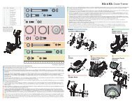
8. Locate the LEFT HANDRAIL (9). With the plastic trim facing<br />
upward, slide the LEFT HANDRAIL into the LEFT HANDRAIL<br />
BRACKET (J) located on the CONSOLE BRIDGE (5). Secure<br />
the LEFT HANDRAIL using two BOLTS (2) and WASHERS<br />
(3) from the side as shown. Leave the BOLTS loose at this<br />
time.<br />
Repeat to install the RIGHT HANDRAIL (10).<br />
9. Install the RIGHT and LEFT END GASKETS (11<br />
& 12) onto the ERGO CROSSBAR (13).<br />
The GASKETS are marked with an “L”<br />
(left) or “R” (right) as well as an arrow indicating<br />
the “UP” position.<br />
10. Install the ERGO CROSSBAR (13) to the<br />
HANDRAILS (9 & 10) and CONSOLE BRIDGE (6)<br />
using four SCREWS (14), three SCREWS (39) and<br />
seven WASHERS (10). Do not overtighten the SCREWS.<br />
NOTE: ROUTE THE HEART RATE CABLES (L)<br />
UNDER THE MOUNTING TABS AS SHOWN.<br />
BE CAREFUL NOT TO DAMAGE THE<br />
HEART RATE CABLES.<br />
11. Secure the tops of the HANDRAILS (9 &<br />
10) using two SCREWS (39) and WASH-<br />
ERS (8) at each HANDRAIL. Tighten the<br />
SCREWS securely.<br />
12. Tighten all previously installed six UPRIGHT<br />
(2), six BRIDGE (2) and seven ERGO CROSS-<br />
BAR SCREWS (39 & 14) securely.<br />
�� NOTE: PUSH DOWN ON THE FAR ENDS OF THE<br />
HANDRAILS TO VERIFY ALL SCREWS ARE LOCKED IN<br />
PLACE.<br />
13. From under the CONSOLE BRIDGE (5), install the MAS-<br />
TER WIRE HARNESS (15) to the CONSOLE (D)<br />
and HEART RATE (L) CABLES. WIRE-TIE (M)<br />
the cables to the CONSOLE BRIDGE as<br />
shown.<br />
Feed the combined connector upward to the<br />
back of the CONSOLE BRACKET (6).<br />
Attach the FERRITE (W) to the inside of the<br />
user left CONSOLE BRACKET POST (X).<br />
Carefully secure the MASTER WIRE HARNESS to<br />
the CONSOLE BRACKET using CABLE TIES (40)<br />
14. Connect the C-SAFE EXTENSION CABLE (Y) to the<br />
C-SAFE SPLITTER (Z).<br />
15. Slide the TOP COVER (16) over the CONSOLE<br />
BRACKET (6) and onto the CONSOLE BRIDGE (5).<br />
Secure it using six SCREWS (7). Tighten the<br />
SCREWS securely.<br />
NOTE: BE SURE THE TOP COVER FULLY SEATS<br />
INTO THE ERGO CROSSBAR GASKETS.<br />
16. Locate the RIGHT OUTER HANDRAIL COVER (17).<br />
Align it onto the RIGHT HANDRAIL (10) as shown and secure<br />
using six SCREWS (7). Tighten the SCREWS securely.<br />
NOTE: ONE SCREW IS LOCATED AT THE FRONT OF THE<br />
UNIT.<br />
Repeat for the LEFT OUTER HANDRAIL COVER (18).<br />
17. Locate the RIGHT INNER HANDRAIL COVER (19). Align it<br />
onto the RIGHT HANDRAIL (10) as shown and secure<br />
using five SCREWS (7). Tighten the SCREWS securely.<br />
NOTE: BE SURE TO ENGAGE THE TOP TABS UNDER<br />
THE PLASTIC RAIL OF THE RIGHT HANDRAIL.<br />
Repeat for the LEFT INNER HANDRAIL COVER (20).<br />
13<br />
2<br />
3<br />
J<br />
39<br />
8<br />
5<br />
9<br />
12<br />
14<br />
8<br />
N<br />
L<br />
6<br />
14 8 39<br />
8<br />
L W<br />
X<br />
13<br />
10<br />
M G H Z Y 15 D E<br />
11<br />
5
18. Locate the BOTTOM COVER (21). Remove the ACCESS<br />
DOOR (N) and set it aside. Drop the POLAR CABLE (O)<br />
through the opening. Install the BOTTOM COVER to the<br />
CONSOLE BRIDGE (5) using twelve SCREWS (7).<br />
Connect the POLAR CABLE to the connector located<br />
under the CONSOLE BRIDGE. Tighten the SCREWS<br />
securely.<br />
NOTE: BE SURE THE BOTTOM COVER FULLY<br />
SEATS INTO THE ERGO CROSSBAR GASKETS.<br />
NOTE: BE SURE THE BOTTOM COVER IS FULLY<br />
SEATED TO THE TOP COVER AND ARMS.<br />
19. Attach the FRONT NECK SHROUD (22) using two<br />
SCREWS (7). Tighten the SCREWS securely.<br />
20. Position the ACTIVITY ZONE ASSEMBLY (23) near<br />
the ERGO CROSSBAR (13) as shown. Connect the<br />
ACTIVITY ZONE FLAT RIBBON CABLE (P) and<br />
EMERGENCY STOP CABLE (Q). Place the ACTIVITY<br />
ZONE ASSEMBLY over the TOP and BOTTOM COV-<br />
ERS (16 & 21) and secure using two SCREWS (14) through<br />
the access door in the BOTTOM COVER. Tighten the<br />
SCREWS until the ACTIVITY ZONE ASSEMBLY is tight<br />
against the TOP and BOTTOM COVERS. Do not overtighten<br />
the SCREWS.<br />
NOTE: BE SURE TO ROUTE THE FLAT RIBBON CABLE (R)<br />
OVER THE ERGO CROSSBAR (13).<br />
NOTE: BE SURE TO ROUTE THE EMERGENCY STOP<br />
CABLE (R) THROUGH THE NOTCH IN THE BOTTOM<br />
COVER.<br />
21. Replace the BOTTOM COVER ACCESS DOOR (N).<br />
22. Position the CONSOLE (24) near the CONSOLE<br />
BRACKET (6). Connect all cables. Secure the<br />
CONSOLE to the CONSOLE BRACKET using<br />
four SCREWS (25) (found in separate bag).<br />
Tighten the SCREWS securely. Do not overtighten<br />
the SCREWS.<br />
NOTE: BE CAREFUL NOT TO DAMAGE<br />
THE CABLES WHEN INSTALLING THE<br />
CONSOLE.<br />
23. If not already in place, install the LCD<br />
ACCESS COVER (26) to the REAR CON-<br />
SOLE COVER (27).<br />
Install the REAR CONSOLE COVER to the<br />
CONSOLE BRACKET (6) using two<br />
SCREWS (7). Tighten the SCREWS<br />
securely. Do not overtighten the<br />
SCREWS.<br />
24. Install the REAR ENDCAPS (28 & 29)<br />
using two SCREWS (30) each.Tighten the<br />
SCREWS securely. Do not overtighten the<br />
SCREWS.<br />
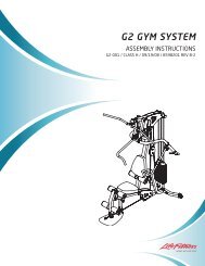
25. Locate the LEFT SIDE EXTRUSION (31). Remove the<br />
liners from the four HOOK AND LOOP FASTENERS (S)<br />
exposing the adhesive.
26. Remove the protective backing from the four HOOK AND LOOP FASTENERS (S) located on the back of the LEFT<br />
SIDE EXTRUSION (31). Align the LEFT SIDE EXTRUSION with the channel in the LEFT SIDERAIL (T) and REAR<br />
ENDCAP (29) as shown. Tilt and engage the LEFT SIDE EXTRUSION to the LEFT SIDERAIL. Press firmly on the<br />
underside of the LEFT SIDE EXTRUSION to secure the HOOK AND LOOP FASTENERS to the frame.<br />
Install one FOAM STRIP (32) between the SIDE RAIL and LEFT SIDE EXTRUSION.<br />
Repeat to install the RIGHT SIDE EXTRUSION (33) to the RIGHT SIDERAIL (U).<br />
NOTE: BE SURE THE TREADMILL IS IN THE FINAL LOCATION FOR USE BEFORE INSTALLING THE LEFT<br />
AND RIGHT EXTRUSIONS.<br />
27. Install the LEFT (34) and RIGHT (35) UPRIGHT COVERS using two SCREWS (30) and one SCREWS (36) each.<br />
Tighten the SCREWS securely. Do not overtighten the SCREWS.<br />
Press inward on the UPRIGHT COVER and engage the pre-installed SCREW (V) located at the rear of each<br />
UPRIGHT COVER.<br />
28. Reinstall the MOTOR COVER (B) using the six previously removed SCREWS (A). Tighten the SCREWS securely.<br />
Do not overtighten the SCREWS.<br />
29. Install the GROMMETS (37) into the screw holes of the INNER HANDRAIL COVERS.<br />
30. Install the CUP HOLDERS (38).<br />
NOTE: BE SURE THE TABS ENGAGE FIRST AND TILT INTO PLACE.<br />
31 The treadmill striding belt must be “walked-in” for five minutes after assembly is complete.<br />
Plug the treadmill into an appropriate outlet. Turn the treadmill on at the on/off switch. Select QUICK START from<br />
the console. Increase the speed to 3 mph (4.8 km/h). Start walking in the front left corner of the walking surface<br />
and drift to the back, move to the center of the deck and walk towards the front, and finally walking to the right<br />
corner and drifting to the back. Continue pattern for five minutes.<br />
32. Refer to the Operation Manual for power requirements, proper line cord routing, and other critical product information<br />
before connecting the treadmill to a power source. A digital version of the Operation Manual can be found on<br />
the attached CD.<br />
28 30<br />
B<br />
30<br />
35<br />
4<br />
V<br />
A<br />
36<br />
1<br />
31<br />
U<br />
S<br />
30<br />
T<br />
34<br />
29<br />
32<br />
30
IMPORTANT!<br />
CHECK THE BELT EDGE UNDER THE TREADMILL TO VERIFY THE BELT DOES NOT INTERFERE WITH LIFE-<br />
SPRING BRACKETS AND THE BELT IS PROPERLY SET WITHIN THE BELT GUIDES.<br />
Physical Dimensions:<br />
Length 80 inches / 203 centimeters<br />
Width 37 inches / 94 centimeters<br />
Height 62.25 inches / 158 centimeters<br />
Weight <strong>Platinum</strong> <strong>Club</strong> <strong>Series</strong> 7”: 450 pounds / 204 kilograms<br />
<strong>Platinum</strong> <strong>Club</strong> <strong>Series</strong> 15”: 455 pounds / 206 kilograms<br />
Step-up Height: 9.5 inches / 24 centimeters<br />
PRE-OPERATION CHECKLIST (A digital version of the Operation Manual can be found on the attached CD.)<br />
� Ensure that all fasteners are tight.<br />
� Make sure the STRIDING BELT is properly tensioned and aligned according to the Operation Manual.<br />
� Check the operation of the STOP switch and tether switch assembly.<br />
(See Operation Manual.)<br />
� Confirm the display console is set to English or Metric units.<br />
(See Optional Settings ENG/MET in Operation Manual.)<br />
� Refer to the Operation Manual for real time clock setting.<br />
� Read the entire Operation Manual before using the treadmill.<br />
LISTE DES VÉRIFICATIONS À EFFECTUER AVANT LA MISE EN MARCHE<br />
(Une version électronique du Manuel de l'utilisateur peut être trouvée sur le CD)<br />
� Vérifiez si tous les dispositifs de fixation sont serrés.<br />
� Assurez-vous que le TAPIS est bien tendu et aligné, conformément aux instructions du manuel d'utilisation.<br />
� Vérifiez le fonctionnement de l'interrupteur d'ARRÊT et reliez-le<br />
(cf. Manuel de l'utilisateur).<br />
� Vérifiez si la console d'affichage est sur le système métrique ou anglais.<br />
(Référez-vous aux réglages facultatifs relatifs aux systèmes de mesure dans le Manuel de l'utilisateur.)<br />
� Consultez le Manuel de l'utilisateur pour le réglage de l'horloge en temps réel.<br />
� Lisez le Manuel de l'utilisateur dans son intégralité avant d'utiliser le tapis roulant.<br />
Before attempting to operate your <strong>Treadmill</strong>, it is imperative that you familiarize yourself with the contents of the<br />
Operation Manual. If your <strong>Life</strong> <strong>Fitness</strong> treadmill does not respond as described in the OPERATION MANUAL contact the<br />
nearest <strong>Life</strong> <strong>Fitness</strong> Service Center as listed in the OPERATION MANUAL.<br />
<strong>Life</strong> <strong>Fitness</strong> Customer Support Services<br />
(800) 351-3737 or (847) 451-0036<br />
Prior to your call, please be sure you have located and noted the<br />
MODEL NUMBER & SERIAL NUMBER.<br />
The Model and Serial number are located behind the left end cap of the unit.<br />
©2007 <strong>Life</strong> <strong>Fitness</strong>, a division of Brunswick Corporation. All rights reserved.<br />
<strong>Life</strong> <strong>Fitness</strong> is a trademarks of Brunswick Corporation.<br />
Polar is a registered trademark of Polar Electro, Inc. M051-00K65-A020 09.07