Virtual Connect SAN Cookbook.pdf - Sallustio.ch
Virtual Connect SAN Cookbook.pdf - Sallustio.ch
Virtual Connect SAN Cookbook.pdf - Sallustio.ch

Create successful ePaper yourself
Turn your PDF publications into a flip-book with our unique Google optimized e-Paper software.
HP <strong>Virtual</strong> <strong>Connect</strong> Fibre Channel Networking<br />
Scenarios<br />
<strong>Cookbook</strong><br />
Part Number c01702940<br />
Second Edition (May 2011)
© Copyright 2009 Hewlett-Packard Development Company, L.P.<br />
The information contained herein is subject to <strong>ch</strong>ange without notice. The only warranties for HP products and services are set forth in the express<br />
warranty statements accompanying su<strong>ch</strong> products and services. Nothing herein should be construed as constituting an additional warranty. HP<br />
shall not be liable for te<strong>ch</strong>nical or editorial errors or omissions contained herein.<br />
Confidential computer software. Valid license from HP required for possession, use or copying. Consistent with FAR 12.211 and 12.212,<br />
Commercial Computer Software, Computer Software Documentation, and Te<strong>ch</strong>nical Data for Commercial Items are licensed to the U.S.<br />
Government under vendor‘s standard commercial license.<br />
Microsoft, Windows, and Windows Server are U.S. registered trademarks of Microsoft Corporation. Intel, Pentium, and Itanium are trademarks<br />
or registered trademarks of Intel Corporation or its subsidiaries in the United States and other countries. UNIX is a registered trademark of The<br />
Open Group.<br />
Intended audience<br />
This document is for the person who installs, administers, and troubleshoots HP BladeSystem c-Class products. Only persons experienced in<br />
server blade te<strong>ch</strong>nology and configuration should attempt these procedures. HP assumes you are qualified in the servicing of computer<br />
equipment and trained in recognizing hazards in products with hazardous energy levels.
Contents<br />
About this document ...................................................................................................................... 6<br />
Introduction ................................................................................................................................................. 6<br />
Considerations and concepts ......................................................................................................... 7<br />
Key takeaways ............................................................................................................................................ 7<br />
Description of the VC <strong>SAN</strong> modules ............................................................................................................... 8<br />
<strong>Virtual</strong> <strong>Connect</strong> Fibre Channel support ........................................................................................................... 9<br />
Supported VC <strong>SAN</strong> Fabric configuration ...................................................................................................... 11<br />
Multi-enclosure VC Domain configuration ..................................................................................................... 13<br />
Multiple-fabric Support ................................................................................................................................ 15<br />
NPIV ......................................................................................................................................................... 17<br />
Port Group ................................................................................................................................................ 19<br />
Scenario 1: Simplest scenario with multipathing ............................................................................. 25<br />
Overview .................................................................................................................................................. 25<br />
Benefits ..................................................................................................................................................... 26<br />
Considerations ........................................................................................................................................... 26<br />
Requirements ............................................................................................................................................. 26<br />
Installation and configuration ...................................................................................................................... 27<br />
Swit<strong>ch</strong> configuration ......................................................................................................................... 27<br />
VC CLI commands ............................................................................................................................ 27<br />
Configuring the VC module ............................................................................................................... 27<br />
Defining a new VC <strong>SAN</strong> Fabric via GUI ............................................................................................. 27<br />
Defining a new VC <strong>SAN</strong> Fabric via CLI .............................................................................................. 30<br />
Blade Server configuration .......................................................................................................................... 31<br />
Verification ................................................................................................................................................ 31<br />
Summary ................................................................................................................................................... 31<br />
Scenario 2: VC <strong>SAN</strong> fabrics with Dynamic Login Balancing connected to the same redundant <strong>SAN</strong> fabric<br />
................................................................................................................................................ 32<br />
Overview .................................................................................................................................................. 32<br />
Benefits ..................................................................................................................................................... 35<br />
Considerations ........................................................................................................................................... 35<br />
Requirements ............................................................................................................................................. 36<br />
Installation and configuration ...................................................................................................................... 36<br />
Swit<strong>ch</strong> configuration ......................................................................................................................... 36<br />
VC CLI commands ............................................................................................................................ 36<br />
Configuring the VC module ............................................................................................................... 36<br />
Defining a new VC <strong>SAN</strong> Fabric via GUI ............................................................................................. 36<br />
Defining a new VC <strong>SAN</strong> Fabric via CLI .............................................................................................. 40<br />
Blade Server configuration .......................................................................................................................... 41<br />
Verification ................................................................................................................................................ 41<br />
Summary ................................................................................................................................................... 41<br />
Scenario 3: Multiple VC <strong>SAN</strong> fabrics with Dynamic Login Balancing connected to the same redundant<br />
<strong>SAN</strong> fabric with different priority tiers ........................................................................................... 42<br />
Overview .................................................................................................................................................. 42<br />
Benefits ..................................................................................................................................................... 43<br />
Contents 3
Considerations ........................................................................................................................................... 44<br />
Requirements ............................................................................................................................................. 44<br />
Installation and configuration ...................................................................................................................... 44<br />
Swit<strong>ch</strong> configuration ......................................................................................................................... 44<br />
VC CLI commands ............................................................................................................................ 44<br />
Configuring the VC module ............................................................................................................... 44<br />
Defining a new VC <strong>SAN</strong> Fabric via GUI ............................................................................................. 45<br />
Defining a new VC <strong>SAN</strong> Fabric via CLI .............................................................................................. 49<br />
Blade Server configuration .......................................................................................................................... 50<br />
Verification ................................................................................................................................................ 50<br />
Summary ................................................................................................................................................... 52<br />
Scenario 4: Multiple VC <strong>SAN</strong> fabrics with Dynamic Login Balancing connected to several redundant <strong>SAN</strong><br />
fabric with different priority tiers ................................................................................................... 53<br />
Overview .................................................................................................................................................. 53<br />
Benefits ..................................................................................................................................................... 54<br />
Considerations ........................................................................................................................................... 55<br />
Requirements ............................................................................................................................................. 55<br />
Installation and configuration ...................................................................................................................... 55<br />
Swit<strong>ch</strong> configuration ......................................................................................................................... 55<br />
VC CLI commands ............................................................................................................................ 55<br />
Configuring the VC module ............................................................................................................... 55<br />
Defining a new VC <strong>SAN</strong> Fabric via GUI ............................................................................................. 56<br />
Defining a new VC <strong>SAN</strong> Fabric via CLI .............................................................................................. 60<br />
Blade Server configuration .......................................................................................................................... 61<br />
Verification ................................................................................................................................................ 61<br />
Summary ................................................................................................................................................... 63<br />
Scenario 5: <strong>SAN</strong> connectivity with HP <strong>Virtual</strong> <strong>Connect</strong> FlexFabric 10Gb/24-Port module ................... 64<br />
Overview .................................................................................................................................................. 64<br />
<strong>Virtual</strong> connect FlexFabric Uplink Port Mappings ........................................................................................... 66<br />
Requirements ............................................................................................................................................. 68<br />
Installation and configuration ...................................................................................................................... 68<br />
Swit<strong>ch</strong> configuration ......................................................................................................................... 68<br />
VC CLI commands ............................................................................................................................ 68<br />
Configuring the VC FlexFabric module ............................................................................................... 68<br />
Defining a new VC <strong>SAN</strong> Fabric via GUI ............................................................................................. 69<br />
Defining a new VC <strong>SAN</strong> Fabric via CLI .............................................................................................. 75<br />
Blade Server configuration .......................................................................................................................... 76<br />
Verification ................................................................................................................................................ 76<br />
Summary ................................................................................................................................................... 76<br />
Scenario 6: Adding VC Fabric uplink ports with Dynamic Login Balancing to an existing VC <strong>SAN</strong> fabric<br />
................................................................................................................................................ 77<br />
Overview .................................................................................................................................................. 77<br />
Benefits ..................................................................................................................................................... 77<br />
Initial configuration..................................................................................................................................... 77<br />
Adding an additional uplink port ................................................................................................................. 82<br />
Via the GUI ..................................................................................................................................... 82<br />
Via the CLI....................................................................................................................................... 83<br />
Login Redistribution .................................................................................................................................... 84<br />
Manual Login Redistribution via the GUI ............................................................................................. 86<br />
Manual Login Redistribution via the CLI .............................................................................................. 87<br />
Verification ................................................................................................................................................ 88<br />
Contents 4
Summary ................................................................................................................................................... 89<br />
Scenario 6: Cisco MDS Dynamic Port V<strong>SAN</strong> Membership ............................................................... 90<br />
Overview .................................................................................................................................................. 90<br />
Benefits ..................................................................................................................................................... 90<br />
Requirements ............................................................................................................................................. 90<br />
Installation and configuration ...................................................................................................................... 90<br />
Summary ................................................................................................................................................... 94<br />
Appendix A: Blade Server configuration with <strong>Virtual</strong> <strong>Connect</strong> Fibre Channel Modules ........................ 95<br />
Defining a Server Profile with FC <strong>Connect</strong>ions, via GUI .................................................................................. 95<br />
Defining a Server Profile with FC <strong>Connect</strong>ions, via CLI ................................................................................... 99<br />
Defining a Boot from <strong>SAN</strong> Server Profile via GUI .......................................................................................... 99<br />
Defining a Boot from <strong>SAN</strong> Server Profile via CLI .......................................................................................... 102<br />
Appendix B: Blade Server configuration with <strong>Virtual</strong> <strong>Connect</strong> FlexFabric Modules ............................ 103<br />
Defining a Server Profile with FCoE <strong>Connect</strong>ions, via GUI ............................................................................ 103<br />
Defining a Server Profile with FCoE <strong>Connect</strong>ions, via CLI ............................................................................. 107<br />
Defining a Boot from <strong>SAN</strong> Server Profile via GUI ........................................................................................ 107<br />
Defining a Boot from <strong>SAN</strong> Server Profile via CLI .......................................................................................... 110<br />
Appendix C: Brocade <strong>SAN</strong> swit<strong>ch</strong> NPIV configuration .................................................................. 111<br />
Enabling NPIV using the GUI ..................................................................................................................... 111<br />
Enabling NPIV using the CLI ...................................................................................................................... 112<br />
Recommendations .................................................................................................................................... 114<br />
Appendix D: Cisco MDS <strong>SAN</strong> swit<strong>ch</strong> NPIV configuration .............................................................. 115<br />
Enabling NPIV using the GUI ..................................................................................................................... 115<br />
Enabling NPIV using the CLI ...................................................................................................................... 118<br />
Appendix E: Cisco Nexus Swit<strong>ch</strong> NPIV configuration .................................................................... 120<br />
Enabling NPIV using the GUI ..................................................................................................................... 120<br />
Enabling NPIV using the CLI ...................................................................................................................... 123<br />
Appendix F: Static Login Distribution Scenario with VC Firmware 1.24 and earlier .......................... 127<br />
Overview ................................................................................................................................................ 127<br />
Benefits ................................................................................................................................................... 127<br />
Requirements ........................................................................................................................................... 127<br />
Installation and configuration .................................................................................................................... 128<br />
Verification .............................................................................................................................................. 130<br />
Summary ................................................................................................................................................. 131<br />
Appendix G: <strong>Connect</strong>ivity verification and testing ........................................................................ 132<br />
<strong>Connect</strong>ivity verification on the VC module ................................................................................................. 132<br />
<strong>Connect</strong>ivity verification on the upstream <strong>SAN</strong> swit<strong>ch</strong> .................................................................................. 136<br />
Testing the loss of uplink ports ................................................................................................................... 139<br />
Appendix H: Boot from <strong>SAN</strong> troubleshooting ............................................................................... 144<br />
Verification during POST ........................................................................................................................... 144<br />
Boot from <strong>SAN</strong> not activated ........................................................................................................... 144<br />
Boot from <strong>SAN</strong> activated ................................................................................................................ 146<br />
Boot from <strong>SAN</strong> misconfigured ......................................................................................................... 148<br />
Troubleshooting ....................................................................................................................................... 148<br />
Acronyms and abbreviations ...................................................................................................... 149<br />
Reference ................................................................................................................................. 151<br />
Contents 5
About this document<br />
Introduction<br />
This guide details the concepts and implementation steps for integrating HP <strong>Virtual</strong> <strong>Connect</strong> Fibre Channel<br />
modules and HP <strong>Virtual</strong> <strong>Connect</strong> FlexFabric Modules into an existing <strong>SAN</strong> Fabric.<br />
The scenarios in this guide are simplistic while covering a range of typical building blocks to use when<br />
designing a solution.<br />
For more information on BladeSystem and <strong>Virtual</strong> <strong>Connect</strong>, see the HP website<br />
http://www.hp.com/go/blades/<br />
About this document 6
Considerations and concepts<br />
Key takeaways<br />
The most important points to remember when using the <strong>Virtual</strong> <strong>Connect</strong> Fiber Chanel Module or the <strong>Virtual</strong><br />
<strong>Connect</strong> FlexFabric module are:<br />
<br />
<br />
<br />
<br />
The HP VC-FC Module requires an HP <strong>Virtual</strong> <strong>Connect</strong> Ethernet Module to also be installed in<br />
order to be managed (it‘s not the case for HP VC FlexFabric). This is because the VC Ethernet<br />
module contains the processor on whi<strong>ch</strong> the <strong>Virtual</strong> <strong>Connect</strong> Manager firmware runs.<br />
The lack of some special features that is available in standard FC swit<strong>ch</strong>es like ISL Trunking, QoS,<br />
long-distance support, and so on, for the external links from VC-FC to the core swit<strong>ch</strong>. ISL<br />
Trunking, Port Channeling between a VC module and an upstream Fibre Channel swit<strong>ch</strong> are not<br />
supported because <strong>Virtual</strong> <strong>Connect</strong> Fibre Channel modules must be connected to a data center<br />
Fibre Channel swit<strong>ch</strong> that supports N_Port_ID virtualization (NPIV). The NPIV standard requires<br />
external ports to be N_Ports and not E_Ports or F_Ports required for trunking.<br />
NPIV support is required in the FC swit<strong>ch</strong>es that connect to the HP VC-FC and HP FlexFabric<br />
Modules —an issue if the FC swit<strong>ch</strong>es cannot be upgraded to latest firmware.<br />
Does not support direct storage atta<strong>ch</strong>ment (requires at least one external FC swit<strong>ch</strong>) because VC<br />
uses an N-port uplink requires to be connected to a FC swit<strong>ch</strong>, it can be connected to data center<br />
Brocade, McData, Cisco, and Qlogic FC swit<strong>ch</strong>es that support the NPIV protocol.<br />
Considerations and concepts 7
Description of the VC <strong>SAN</strong> modules<br />
HP <strong>Virtual</strong> <strong>Connect</strong> 4Gb 20-Port Fibre Channel Module<br />
4 Uplink ports 4Gb FC [1/2/4 Gb]<br />
16 Downlink ports [1/2/4 Gb]<br />
Up to 128 virtual ma<strong>ch</strong>ines running on the<br />
same physical server to access separate<br />
storage resources<br />
HP <strong>Virtual</strong> <strong>Connect</strong> 8Gb 20-Port Fibre Channel Module<br />
4 Uplink ports 8Gb FC [2/4/8 Gb]<br />
16 Downlink ports [1/2/4/8 Gb]<br />
Up to 128 virtual ma<strong>ch</strong>ines running on the<br />
same physical server to access separate<br />
storage resources<br />
HP <strong>Virtual</strong> <strong>Connect</strong> 8Gb 24-Port Fibre Channel Module<br />
8 Uplink ports 8Gb FC [2/4/8 Gb]<br />
16 Downlink ports [1/2/4/8 Gb]<br />
Up to 255 virtual ma<strong>ch</strong>ines running on the<br />
same physical server to access separate<br />
storage resources<br />
HP <strong>Virtual</strong> <strong>Connect</strong> FlexFabric 10Gb/24-Port Module<br />
X1 – X4<br />
Uplink ports available<br />
for FC connection<br />
[2/4/8 Gb]<br />
4 Uplink ports 8Gb FC [2/4/8 Gb]<br />
16 Downlink ports [FlexHBA: any speed]<br />
Up to 255 virtual ma<strong>ch</strong>ines running on the<br />
same physical server to access separate<br />
storage resources<br />
Can be configurable<br />
as well as<br />
Ethernet 10Gb<br />
Considerations and concepts 8
<strong>Virtual</strong> <strong>Connect</strong> Fibre Channel support<br />
<strong>Virtual</strong> <strong>Connect</strong> connectivity Stream documents describing the different configuration supported by HP are<br />
available on www.hp.com/storage/spock (HP Passport is required; if you are a new user, please click on<br />
―please register‖).<br />
For any specific supported Fabric OS, <strong>SAN</strong>-OS & NX-OS versions for <strong>SAN</strong>s involving 3rd-party<br />
equipment, please consult your 3rd-party vendor.<br />
<strong>Virtual</strong> <strong>Connect</strong><br />
From the HP StorageWorks SPOCK homepage, select <strong>Virtual</strong> <strong>Connect</strong> on the bottom left menu in the<br />
‗Other Hardware‘ section or use the following link to access directly to the VC web page:<br />
http://h20272.www2.hp.com/Pages/spock2Html.aspx?htmlFile=hw_virtual_connect.html<br />
Three connectivity stream documents are currently available, one for ea<strong>ch</strong> <strong>Virtual</strong> <strong>Connect</strong> model type:<br />
FC and FCoE swit<strong>ch</strong>es<br />
It‘s interesting as well to visit the SPOCK SWITCH page to get the supported configurations of the<br />
upstream swit<strong>ch</strong> connected to <strong>Virtual</strong> <strong>Connect</strong>. Details about firmware and OS versions are usually<br />
provided.<br />
From the HP StorageWorks SPOCK homepage, select Swit<strong>ch</strong> on the bottom left menu in the ‗Other<br />
Hardware‘ section or use the following link to access directly to the swit<strong>ch</strong> web page:<br />
http://h20272.www2.hp.com/Pages/spock2Html.aspx?htmlFile=hw_swit<strong>ch</strong>es.html<br />
Considerations and concepts 9
Considerations and concepts 10
Supported VC <strong>SAN</strong> Fabric configuration<br />
To form a <strong>Virtual</strong> <strong>Connect</strong> <strong>SAN</strong> fabric correctly, participating uplinks must be connected to the same <strong>SAN</strong><br />
fabric:<br />
VC <strong>SAN</strong> 1 VC <strong>SAN</strong> 2<br />
VC <strong>SAN</strong> 1<br />
VC <strong>SAN</strong> Fabrics defined<br />
in the VC Domain<br />
VC-FC Module<br />
VC-FC Module<br />
Fabric 1 Fabric 2<br />
Fabric 1 Fabric 2<br />
External Datacenter<br />
<strong>SAN</strong> Fabrics<br />
Different <strong>Virtual</strong> <strong>Connect</strong> <strong>SAN</strong> fabrics can be connected to the same <strong>SAN</strong> fabric:<br />
VC <strong>SAN</strong> 1 VC <strong>SAN</strong> 2<br />
VC-FC Module<br />
Fabric 1<br />
This configuration gives you more granular control over whi<strong>ch</strong> server blades use ea<strong>ch</strong> VC-FC port, while<br />
also enabling the distribution of servers according to their I/O workloads.<br />
Considerations and concepts 11
10/100Base-TX<br />
6 15 16<br />
13 14<br />
11 12<br />
9 10<br />
7 8<br />
1 2 3 4 21 22 31 32<br />
29 30<br />
27 28<br />
25 26<br />
23 24<br />
17 18 19 20 37 38 47 48<br />
45 46<br />
43 44<br />
41 42<br />
39 40<br />
33 34 35 36<br />
5<br />
H3C S3600<br />
Speed:Green=100Mbps,Yellow=10Mbps Duplex:Green=Full Duplex,Yellow=Half Duplex Power:Green=DeliveringPower,Yellow=Fault,Flashing Green=Over Budget<br />
Series<br />
12Vdc<br />
HP StorageWorks<br />
4/32B <strong>SAN</strong> Swit<strong>ch</strong><br />
0 4 1 5 2 6 3 7<br />
8 12 9 13 10 14 1 15<br />
16 20 17 21 18 2 19 23<br />
24 28 25 29 26 30 27 31<br />
Console<br />
1000Base-X<br />
52<br />
51<br />
50<br />
49<br />
Unit<br />
20%<br />
40%<br />
60%<br />
80%<br />
100%<br />
Mode<br />
RPS<br />
PWR<br />
Flashing=PoE<br />
Yellow=Duplex<br />
Green=Speed<br />
PS 1<br />
PS<br />
6<br />
UID<br />
X1<br />
1 2 DP1-A DP1-B<br />
1 2 DP1-A DP1-B<br />
HP VC Flex-10 Enet Module X1 X2 X3 X4 X5 X6<br />
UID<br />
HP 4Gb VC-FC Module<br />
iLO<br />
Reset<br />
SHARED<br />
PS<br />
5<br />
1 2 3 4<br />
Active<br />
UID<br />
Cntrl 1<br />
PS<br />
4<br />
12Vdc<br />
UID<br />
SHARED: UPLINK or X-LINK<br />
X7 X8<br />
Enclosure<br />
UID<br />
Mfg<br />
Remove management modules before ejecting sleeve<br />
Mgmt<br />
UID<br />
X1<br />
Enclosure Interlink<br />
HP VC Flex-10 Enet Module X1 X2 X3 X4 X5 X6<br />
UID<br />
HP 4Gb VC-FC Module<br />
SHARED<br />
iLO<br />
Reset<br />
1 2 3 4<br />
Active<br />
12Vdc<br />
UID<br />
PS<br />
3<br />
Cntrl 2<br />
HP StorageWorks<br />
4/32B <strong>SAN</strong> Swit<strong>ch</strong><br />
UID<br />
SHARED: UPLINK or X-LINK<br />
X7 X8<br />
PS<br />
2<br />
UID<br />
PS<br />
1<br />
Mfg<br />
PS 2<br />
0 4 1 5 2 6 3 7<br />
8 12 9 13 10 14 1 15<br />
16 20 17 21 18 2 19 23<br />
24 28 25 29 26 30 27 31<br />
12Vdc<br />
10/100Base-TX<br />
6 15 16<br />
13 14<br />
11 12<br />
9 10<br />
7 8<br />
1 2 3 4 21 22 31 32<br />
29 30<br />
27 28<br />
25 26<br />
23 24<br />
17 18 19 20 37 38 47 48<br />
45 46<br />
43 44<br />
41 42<br />
39 40<br />
33 34 35 36<br />
5<br />
H3C S3600<br />
Speed:Green=100Mbps,Yellow=10Mbps Duplex:Green=Full Duplex,Yellow=Half Duplex Power:Green=DeliveringPower,Yellow=Fault,Flashing Green=Over Budget<br />
Series<br />
Console<br />
1000Base-X<br />
52<br />
51<br />
50<br />
49<br />
Unit<br />
20%<br />
40%<br />
60%<br />
80%<br />
100%<br />
Mode<br />
RPS<br />
PWR<br />
Flashing=PoE<br />
Yellow=Duplex<br />
Green=Speed<br />
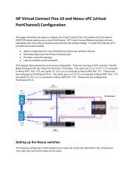
The following diagrams show two typical supported configurations for <strong>Virtual</strong> <strong>Connect</strong> Fibre Channel<br />
8Gb 20-port and <strong>Virtual</strong> <strong>Connect</strong> FlexFabric modules:<br />
Figure 1: Typical FC configuration with VC-FC 8Gb 20-port modules - Redundant paths - server-to-Fabric<br />
uplink ratio 4:1<br />
Storage Array<br />
Storage Controller<br />
Storage Controller<br />
Fabric-1<br />
Fabric-2<br />
<strong>SAN</strong> Swit<strong>ch</strong> A<br />
<strong>SAN</strong> uplink<br />
connection<br />
<strong>SAN</strong> Swit<strong>ch</strong> B<br />
LAN Swit<strong>ch</strong> A<br />
LAN Swit<strong>ch</strong> B<br />
FAN<br />
1<br />
FAN<br />
5<br />
Ethernet uplink<br />
connection<br />
SUS-1<br />
1<br />
3<br />
2<br />
4<br />
SUS-2<br />
Ethernet uplink<br />
connection<br />
5<br />
6<br />
7<br />
8<br />
OA1<br />
OA2<br />
FAN<br />
6<br />
FAN<br />
10<br />
HP BladeSystem c7000<br />
Considerations and concepts 12
10/100Base-TX<br />
6 15 16<br />
13 14<br />
11 12<br />
9 10<br />
7 8<br />
1 2 3 4 21 22 31 32<br />
29 30<br />
27 28<br />
25 26<br />
23 24<br />
17 18 19 20 37 38 47 48<br />
45 46<br />
43 44<br />
41 42<br />
39 40<br />
33 34 35 36<br />
5<br />
H3C S3600<br />
Speed:Green=100Mbps,Yellow=10Mbps Duplex:Green=Full Duplex,Yellow=Half Duplex Power:Green=DeliveringPower,Yellow=Fault,Flashing Green=Over Budget<br />
Series<br />
12Vdc<br />
HP StorageWorks<br />
4/32B <strong>SAN</strong> Swit<strong>ch</strong><br />
0 4 1 5 2 6 3 7<br />
8 12 9 13 10 14 1 15<br />
16 20 17 21 18 2 19 23<br />
24 28 25 29 26 30 27 31<br />
Console<br />
1000Base-X<br />
52<br />
51<br />
50<br />
49<br />
Unit<br />
20%<br />
40%<br />
60%<br />
80%<br />
100%<br />
Mode<br />
RPS<br />
PWR<br />
Flashing=PoE<br />
Yellow=Duplex<br />
Green=Speed<br />
PS 1<br />
PS<br />
6<br />
1 2 DP1-A DP1-B<br />
1 2 DP1-A DP1-B<br />
UID<br />
HP VC FlexFabric 10Gb/24-Port Module<br />
iLO<br />
Reset<br />
S H A R E D : U P L I N K o r X - L I N K<br />
X1 X2 X3 X4<br />
X5 X6 X7 X8<br />
Active<br />
PS<br />
5<br />
UID<br />
Cntrl 1<br />
PS<br />
4<br />
12Vdc<br />
UID<br />
Mfg<br />
Enclosure<br />
UID<br />
Mgmt<br />
Remove management modules before ejecting sleeve<br />
UID<br />
Enclosure Interlink<br />
S H A R E D : U P L I N K o r X - L I N K<br />
X1 X2 X3 X4<br />
X5 X6 X7 X8<br />
HP VC FlexFabric 10Gb/24-Port Module<br />
iLO<br />
Reset<br />
12Vdc<br />
Active<br />
UID<br />
PS<br />
3<br />
Cntrl 2<br />
HP StorageWorks<br />
4/32B <strong>SAN</strong> Swit<strong>ch</strong><br />
UID<br />
PS<br />
2<br />
UID<br />
Mfg<br />
PS<br />
1<br />
PS 2<br />
0 4 1 5 2 6 3 7<br />
8 12 9 13 10 14 1 15<br />
16 20 17 21 18 2 19 23<br />
24 28 25 29 26 30 27 31<br />
12Vdc<br />
10/100Base-TX<br />
6 15 16<br />
13 14<br />
11 12<br />
9 10<br />
7 8<br />
1 2 3 4 21 22 31 32<br />
29 30<br />
27 28<br />
25 26<br />
23 24<br />
17 18 19 20 37 38 47 48<br />
45 46<br />
43 44<br />
41 42<br />
39 40<br />
33 34 35 36<br />
5<br />
H3C S3600<br />
Speed:Green=100Mbps,Yellow=10Mbps Duplex:Green=Full Duplex,Yellow=Half Duplex Power:Green=DeliveringPower,Yellow=Fault,Flashing Green=Over Budget<br />
Series<br />
Console<br />
1000Base-X<br />
52<br />
51<br />
50<br />
49<br />
Unit<br />
20%<br />
40%<br />
60%<br />
80%<br />
100%<br />
Mode<br />
RPS<br />
PWR<br />
Flashing=PoE<br />
Yellow=Duplex<br />
Green=Speed<br />
Figure 2: Typical FC configuration with VC FlexFabric modules - Redundant paths - server-to- Fabric uplink<br />
ratio 4:1<br />
Storage Array<br />
Storage Controller<br />
Storage Controller<br />
Fabric-1<br />
Fabric-2<br />
<strong>SAN</strong> Swit<strong>ch</strong> A<br />
<strong>SAN</strong> uplink<br />
connection<br />
<strong>SAN</strong> Swit<strong>ch</strong> B<br />
LAN Swit<strong>ch</strong> A<br />
LAN Swit<strong>ch</strong> B<br />
Ethernet uplink<br />
connection<br />
SUS-1<br />
FAN<br />
1<br />
1<br />
3<br />
FAN<br />
5<br />
2<br />
4<br />
SUS-2<br />
Ethernet uplink<br />
connection<br />
5<br />
6<br />
7<br />
8<br />
OA1<br />
OA2<br />
FAN<br />
6<br />
FAN<br />
10<br />
HP BladeSystem c7000<br />
For more information about enclosure support, configuration guidelines, see the <strong>Virtual</strong> <strong>Connect</strong> Setup<br />
and Installation Guide<br />
http://bizsupport2.austin.hp.com/bc/docs/support/SupportManual/c01732252/c01732252.<strong>pdf</strong><br />
Multi-enclosure VC Domain configuration<br />
<strong>Virtual</strong> <strong>Connect</strong> version 2.10 and higher supports the connection of up to four c7000 enclosures, whi<strong>ch</strong><br />
can reduce the number of network connections per rack and also enables a single VC manager to control<br />
multiple enclosures.<br />
A single set of cables can be used to carry all external Ethernet traffic from a single rack but the Fibre<br />
Channel data packets are not transmitted between modules therefore ea<strong>ch</strong> <strong>Virtual</strong> <strong>Connect</strong> Fiber Channel<br />
module must be connected to the <strong>SAN</strong> Fabrics.<br />
Also when VC-FC is implemented in a multi-enclosure domain, all enclosures must have identical VC-FC<br />
module placement and cabling. This ensures that the profile mobility is maintained, so that when a profile<br />
is moved from one enclosure to another within the stacked VC Domain, <strong>SAN</strong> connectivity is preserved.<br />
Considerations and concepts 13
10/100Base-TX<br />
6 15 16<br />
13 14<br />
11 12<br />
9 10<br />
7 8<br />
1 2 3 4 21 22 31 32<br />
29 30<br />
27 28<br />
25 26<br />
23 24<br />
17 18 19 20 37 38 47 48<br />
45 46<br />
43 44<br />
41 42<br />
39 40<br />
33 34 35 36<br />
5<br />
H3C S3600<br />
Speed:Green=100Mbps,Yellow=10Mbps Duplex:Green=Full Duplex,Yellow=Half Duplex Power:Green=DeliveringPower,Yellow=Fault,Flashing Green=Over Budget<br />
Series<br />
12Vdc<br />
HP StorageWorks<br />
4/32B <strong>SAN</strong> Swit<strong>ch</strong><br />
0 4 1 5 2 6 3 7<br />
8 12 9 13 10 14 1 15<br />
16 20 17 21 18 2 19 23<br />
24 28 25 29 26 30 27 31<br />
Console<br />
1000Base-X<br />
52<br />
51<br />
50<br />
49<br />
Unit<br />
20%<br />
40%<br />
60%<br />
80%<br />
100%<br />
Mode<br />
RPS<br />
PWR<br />
Flashing=PoE<br />
Yellow=Duplex<br />
Green=Speed<br />
FAN<br />
1<br />
OA1<br />
FAN<br />
6<br />
FAN<br />
1<br />
OA1<br />
FAN<br />
6<br />
PS<br />
6<br />
PS<br />
6<br />
PS 1<br />
UID<br />
UID<br />
X1<br />
HP VC Flex-10 Enet Module X1 X2 X3 X4 X5 X6<br />
UID<br />
HP 4Gb VC-FC Module<br />
iLO<br />
Reset<br />
X1<br />
SHARED<br />
PS<br />
5<br />
PS<br />
5<br />
1 2 3 4<br />
Active<br />
UID<br />
PS<br />
4<br />
HP VC Flex-10 Enet Module X1 X2 X3 X4 X5 X6<br />
UID<br />
HP 4Gb VC-FC Module<br />
iLO<br />
Reset<br />
SHARED<br />
1 2 3 4<br />
Active<br />
UID<br />
Cntrl 1<br />
1 2 DP1-A DP1-B<br />
1 2 DP1-A DP1-B<br />
PS<br />
4<br />
12Vdc<br />
UID<br />
SHARED: UPLINK or X-LINK<br />
X7 X8<br />
Enclosure<br />
UID<br />
Remove management modules before ejecting sleeve<br />
SHARED: UPLINK or X-LINK<br />
X7 X8<br />
Enclosure<br />
UID<br />
Mfg<br />
Remove management modules before ejecting sleeve<br />
Mgmt<br />
UID<br />
X1<br />
Enclosure Interlink<br />
UID<br />
Enclosure Interlink<br />
HP VC Flex-10 Enet Module X1 X2 X3 X4 X5 X6<br />
UID<br />
HP 4Gb VC-FC Module<br />
X1<br />
SHARED<br />
iLO<br />
Reset<br />
1 2 3 4<br />
Active<br />
UID<br />
PS<br />
3<br />
HP VC Flex-10 Enet Module X1 X2 X3 X4 X5 X6<br />
UID<br />
HP 4Gb VC-FC Module<br />
SHARED<br />
iLO<br />
Reset<br />
1 2 3 4<br />
Active<br />
12Vdc<br />
UID<br />
PS<br />
3<br />
Cntrl 2<br />
HP StorageWorks<br />
4/32B <strong>SAN</strong> Swit<strong>ch</strong><br />
UID<br />
SHARED: UPLINK or X-LINK<br />
X7 X8<br />
PS<br />
2<br />
SHARED: UPLINK or X-LINK<br />
X7 X8<br />
PS<br />
2<br />
UID<br />
PS<br />
1<br />
PS<br />
1<br />
Mfg<br />
FAN<br />
5<br />
OA2<br />
FAN<br />
10<br />
FAN<br />
5<br />
OA2<br />
FAN<br />
10<br />
PS 2<br />
0 4 1 5 2 6 3 7<br />
8 12 9 13 10 14 1 15<br />
16 20 17 21 18 2 19 23<br />
24 28 25 29 26 30 27 31<br />
12Vdc<br />
10/100Base-TX<br />
6 15 16<br />
13 14<br />
11 12<br />
9 10<br />
7 8<br />
1 2 3 4 21 22 31 32<br />
29 30<br />
27 28<br />
25 26<br />
23 24<br />
17 18 19 20 37 38 47 48<br />
45 46<br />
43 44<br />
41 42<br />
39 40<br />
33 34 35 36<br />
5<br />
H3C S3600<br />
Speed:Green=100Mbps,Yellow=10Mbps Duplex:Green=Full Duplex,Yellow=Half Duplex Power:Green=DeliveringPower,Yellow=Fault,Flashing Green=Over Budget<br />
Series<br />
Console<br />
1000Base-X<br />
52<br />
51<br />
50<br />
49<br />
Unit<br />
20%<br />
40%<br />
60%<br />
80%<br />
100%<br />
Mode<br />
RPS<br />
PWR<br />
Flashing=PoE<br />
Yellow=Duplex<br />
Green=Speed<br />
Figure 3: Multi-Enclosure Stacking requires all VC-FC modules to be connected to the <strong>SAN</strong>.<br />
Storage Array<br />
Storage Controller<br />
Storage Controller<br />
Fabric-1<br />
Fabric-2<br />
LAN Swit<strong>ch</strong> A<br />
<strong>SAN</strong> Swit<strong>ch</strong> A<br />
<strong>SAN</strong> uplink<br />
connection<br />
<strong>SAN</strong> Swit<strong>ch</strong> B<br />
Ethernet uplink<br />
connection<br />
SUS-1<br />
1<br />
3<br />
2<br />
4<br />
5<br />
6<br />
7<br />
8<br />
1<br />
3<br />
5<br />
2<br />
4<br />
6<br />
Ethernet uplink<br />
connection<br />
LAN Swit<strong>ch</strong> B<br />
7<br />
8<br />
SUS-2<br />
: 10Gb Stack Links<br />
For more information, see the <strong>Virtual</strong> <strong>Connect</strong> Multi-Enclosure Stacking Reference Guide<br />
http://bizsupport2.austin.hp.com/bc/docs/support/SupportManual/c02102153/c02102153.<strong>pdf</strong><br />
Considerations and concepts 14
Multiple-fabric Support<br />
Support for multiple <strong>SAN</strong> fabrics per VC-FC module is provided in VC firmware 1.31 and above. This<br />
feature allows the Storage administrator to assign any of the available VC-FC uplinks to a different <strong>SAN</strong><br />
fabric and dynamically assign server HBAs to the desired <strong>SAN</strong> fabric.<br />
Server 1<br />
Server 2<br />
Server 3<br />
Server 4<br />
HBA1 HBA2 HBA1 HBA2 HBA1 HBA2<br />
HBA1<br />
HBA2<br />
VC <strong>SAN</strong> 1 VC <strong>SAN</strong> 2 VC <strong>SAN</strong> 3 VC <strong>SAN</strong> 4<br />
VC Domain<br />
VC-FC Module<br />
Fabric 1<br />
Fabric 4<br />
Fabric 2 Fabric 3<br />
The <strong>Virtual</strong> <strong>Connect</strong> 4Gb and 8Gb 20-Port Fibre Channel modules support up to 4 <strong>SAN</strong> fabrics:<br />
VC-FC 20-port Module<br />
Fabric 1<br />
Fabric 4<br />
Fabric 2 Fabric 3<br />
Considerations and concepts 15
The <strong>Virtual</strong> <strong>Connect</strong> 8Gb 24-Port Fibre Channel module supports up to 8 <strong>SAN</strong> fabrics:<br />
Fabric 6 Fabric 7<br />
Fabric 5<br />
Fabric 8<br />
VC-FC 8Gb 24-Port Module<br />
Fabric 1<br />
Fabric 4<br />
Fabric 2 Fabric 3<br />
The <strong>Virtual</strong> <strong>Connect</strong> FlexFabric module supports up to 4 <strong>SAN</strong> fabrics:<br />
VC-FlexFabric Module<br />
Fabric 1<br />
Fabric 4<br />
Fabric 2 Fabric 3<br />
Considerations and concepts 16
12Vdc<br />
HP StorageWorks<br />
4/32B <strong>SAN</strong> Swit<strong>ch</strong><br />
0 4 1 5 2 6 3 7<br />
8 12 9 13 10 14 1 15<br />
16 20 17 21 18 2 19 23<br />
24 28 25 29 26 30 27 31<br />
UID<br />
HP 4Gb VC-FC Module<br />
PS 1<br />
Cntrl 1<br />
1 2 DP1-A DP1-B<br />
1 2 DP1-A DP1-B<br />
1 2 3 4<br />
12Vdc<br />
UID<br />
Mfg<br />
Mgmt<br />
HP ProLiant<br />
BL460c<br />
UID<br />
NIC<br />
1<br />
NIC<br />
2<br />
UID<br />
Cntrl 2<br />
HP 4Gb VC-FC Module<br />
UID<br />
UID<br />
12Vdc<br />
Mfg<br />
PS 2<br />
HP StorageWorks<br />
4/32B <strong>SAN</strong> Swit<strong>ch</strong><br />
0 4 1 5 2 6 3 7<br />
8 12 9 13 10 14 1 15<br />
16 20 17 21 18 2 19 23<br />
24 28 25 29 26 30 27 31<br />
1 2 3 4<br />
12Vdc<br />
NPIV<br />
For Fibre Channel connections, HP VC 4Gb FC module, HP VC 8Gb 24-Port FC module, HP VC 8Gb 20-<br />
Port FC module or HP VC FlexFabric 10Gb/24-port module uplinks can be connected only to Fibre<br />
Channel swit<strong>ch</strong> ports that support N_port_ID virtualization (NPIV).<br />
The use of NPIV allows the VC-FC modules to be connected to any swit<strong>ch</strong> supporting the NPIV protocol<br />
like data center Brocade, McData, Cisco, and Qlogic FC swit<strong>ch</strong>es.<br />
To verify that NPIV support is provided and for instructions on enabling this support see the firmware<br />
documentation that ships with the Fibre Channel swit<strong>ch</strong>.<br />
The <strong>SAN</strong> swit<strong>ch</strong> ports connecting to the VC Fabric uplink ports must be sometimes configured to accept<br />
NPIV logins, see "Appendix C: Brocade <strong>SAN</strong> swit<strong>ch</strong> NPIV configuration" or "Appendix D: Cisco <strong>SAN</strong><br />
swit<strong>ch</strong> NPIV configuration" or "Appendix E: Cisco NEXUS <strong>SAN</strong> swit<strong>ch</strong> NPIV configuration" depending on<br />
your swit<strong>ch</strong> model.<br />
Figure 4: NPIV requires a <strong>SAN</strong> swit<strong>ch</strong> between the VC Fabric uplink ports and the Storage Disk Array<br />
Storage Array<br />
Fabric-1<br />
Fabric-2<br />
HBA 1 HBA 2<br />
Blade Server<br />
Considerations and concepts 17
UID<br />
HP 4Gb VC-FC Module<br />
1 2 3 4<br />
PS 1<br />
Cntrl 1<br />
1 2 DP1-A DP1-B<br />
1 2 DP1-A DP1-B<br />
UID<br />
Mfg<br />
HP ProLiant<br />
BL460c<br />
UID<br />
NIC<br />
1<br />
NIC<br />
2<br />
Mgmt<br />
UID<br />
HP 4Gb VC-FC Module<br />
Cntrl 2<br />
UID<br />
UID<br />
Mfg<br />
PS 2<br />
1 2 3 4<br />
Figure 5: VC Fabric uplink ports cannot be connected directly to a Storage Array (no NPIV support)<br />
Storage Array<br />
HBA 1 HBA 2<br />
Blade Server<br />
The VC-FC and VC FlexFabric modules are FC standards-based and are compatible with all other NPIV<br />
standard–compliant swit<strong>ch</strong> products.<br />
Due to the use of NPIV, special features that are available in standard FC swit<strong>ch</strong>es like ISL Trunking, QoS,<br />
extended distances, etc. are not supported with VC-FC and VC FlexFabric.<br />
Considerations and concepts 18
Port Group<br />
Beginning with version 1.31 of <strong>Virtual</strong> <strong>Connect</strong> Manager, users can group multiple VC Fabric uplinks<br />
logically into a <strong>Virtual</strong> <strong>Connect</strong> fabric when atta<strong>ch</strong>ed to the same Fibre Channel <strong>SAN</strong> fabric.<br />
VC Domain<br />
VC <strong>SAN</strong> 1<br />
VC <strong>SAN</strong> 2<br />
VC-FC Module<br />
VC-FC Module<br />
Fabric 1<br />
Fabric 2<br />
There are several benefits with Fabric port grouping; the bandwidth is increased, the server-to-uplink ratio<br />
is improved, a better redundancy is provided with automatic port failover.<br />
Increased bandwidth<br />
Depending on the VC Fiber Channel module and the number of uplinks used, the server-to-uplink ratio<br />
(i.e. oversubscription ratio) is adjustable to 2:1, 4:1, 8:1, or 16:1. So as few as two or as many as 16<br />
servers share one physical link on a fully populated enclosure with 16 servers.<br />
The use of multiple uplinks can truly reduce the risk of congestion.<br />
2:1 oversubscription with 24-port VC-FC modules:<br />
2:1<br />
VC-FC<br />
16 servers 24-port 8 Uplinks<br />
Considerations and concepts 19
4:1 oversubscription with 20-port VC-FC modules and with VC FlexFabric modules:<br />
4:1<br />
VC-FC<br />
16 servers 20-port 4 Uplinks<br />
Dynamic Logins Load Balancing and increased redundancy<br />
When VC Fabric uplinks are grouped into a single fabric, the module uses dynamic login distribution to<br />
load balance the server connections across all available uplink ports.<br />
The port with the least number of logins across the VC <strong>SAN</strong> Fabric is used, when the number of logins is<br />
equal, VC makes a round-robin decision.<br />
Static Uplink Login Distribution has been removed since VC 3.00.<br />
Server 1<br />
Server 2<br />
Server 3<br />
Server 4<br />
HBA1 HBA2 HBA1 HBA2 HBA1 HBA2<br />
HBA1<br />
HBA2<br />
VC Domain<br />
VC <strong>SAN</strong> 1<br />
VC-FC Module<br />
Server 3<br />
Server 2<br />
Server 1<br />
Server 4<br />
Fabric 1<br />
Considerations and concepts 20
Uplink port path failover:<br />
The module uses dynamic login distribution to provide an uplink port path failover that enables server<br />
connections to fail over within the <strong>Virtual</strong> <strong>Connect</strong> fabric.<br />
If a fabric uplink port in the group becomes unavailable, hosts logged in through that uplink are<br />
reconnected automatically to the fabric through the remaining uplink(s) in the group, resulting in autofailover.<br />
Server 1<br />
Server 2<br />
Server 3<br />
Server 4<br />
HBA1 HBA2 HBA1 HBA2 HBA1 HBA2<br />
HBA1<br />
HBA2<br />
VC Domain<br />
VC <strong>SAN</strong> 1<br />
VC-FC Module<br />
Server 3<br />
Server 2<br />
Server 1<br />
Server 4<br />
Fabric 1<br />
This automatic failover saves time and effort whenever there is a link failure between an uplink port on<br />
VC and an external fabric, and allows smooth transition without mu<strong>ch</strong> disruption to the traffic. However,<br />
the hosts will have to perform re-login before resuming their I/O operations.<br />
Considerations and concepts 21
Login Redistribution<br />
If a failed port becomes available again, the logins redistribution (or logins failback) is not automatic<br />
except if the Automatic Login Redistribution available with the VC FlexFabric modules is used.<br />
Server 1<br />
Server 2<br />
Server 3<br />
Server 4<br />
HBA1 HBA2 HBA1 HBA2 HBA1 HBA2<br />
HBA1<br />
HBA2<br />
VC Domain<br />
VC <strong>SAN</strong> 1<br />
VC-FC Module<br />
Server 3<br />
Server 2<br />
Server 1<br />
Server 4<br />
Fabric 1<br />
There are two Login redistribution modes:<br />
<br />
<br />
Manual Login Re-Distribution: When configured, a user is expected to initiate a Login Re-<br />
Distribution request via VC GUI or CLI interfaces.<br />
Automatic Login Re-Distribution: When configured, the VC FlexFabric module initiates Login Re-<br />
Distribution automatically when the time interval specified expires.<br />
Table 1: Manual and Automatic Logins Redistribution support<br />
Login Re-Distribution<br />
Mode<br />
Auto-failover*<br />
Auto-failback**<br />
VC-FC<br />
support<br />
MANUAL YES NO YES<br />
AUTOMATIC<br />
YES<br />
YES after link<br />
stability delay<br />
NO<br />
FlexFabric<br />
support<br />
YES<br />
(default)<br />
YES<br />
*: when a port in the <strong>SAN</strong> Fabric group becomes unavailable<br />
**: when a failed port returns to a good working condition<br />
Considerations and concepts 22
Link stability<br />
This interval defines the number of seconds that the VC fabric uplink(s) have to stabilize before the VC FC<br />
module attempts to load-balance the logins.<br />
The administrator can configure the link stability interval parameter on a VC domain basis.<br />
Automatic Login Redistribution can be enabled for VC FlexFabric. For all legacy VC-FC modules, the<br />
Login Redistribution is manual only.<br />
Considerations and concepts 23
Manual Logins redistribution<br />
To manually redistribute logins on a VC <strong>SAN</strong> fabric, select the VC <strong>SAN</strong> Fabric, then ‗Server connections‘<br />
tab then click ‗Redistribute Logins‘.<br />
'Redistribute Logins' is only valid for a VC <strong>SAN</strong> fabric with Manual Login Distribution.<br />
Considerations and concepts 24
Scenario 1: Simplest scenario with multipathing<br />
Overview<br />
This scenario covers the setup and configuration of two VC <strong>SAN</strong> Fabrics, ea<strong>ch</strong> utilizing a single uplink<br />
connected to a redundant Fabric.<br />
Figure 6: Logical view<br />
on a fully populated enclosure with 16 servers<br />
Server 1<br />
Server 2<br />
Server 3<br />
…<br />
Server 16<br />
HBA1 HBA2<br />
HBA1 HBA2<br />
HBA1 HBA2<br />
…<br />
HBA1<br />
HBA2<br />
VC Domain<br />
Fabric--1<br />
Fabric--2<br />
VC-FC 8Gb<br />
20-port Module<br />
Fabric 1<br />
Fabric 2<br />
Scenario 1: Simplest scenario with multipathing 25
12Vdc<br />
HP StorageWorks<br />
4/32B <strong>SAN</strong> Swit<strong>ch</strong><br />
0 4 1 5 2 6 3 7<br />
8 12 9 13 10 14 1 15<br />
16 20 17 21 18 2 19 23<br />
24 28 25 29 26 30 27 31<br />
UID<br />
HP 4Gb VC-FC Module<br />
PS 1<br />
Cntrl 1<br />
1 2 DP1-A DP1-B<br />
1 2 DP1-A DP1-B<br />
1 2 3 4<br />
12Vdc<br />
UID<br />
Mfg<br />
Mgmt<br />
HP ProLiant<br />
BL460c<br />
UID<br />
NIC<br />
1<br />
NIC<br />
2<br />
UID<br />
Cntrl 2<br />
HP 4Gb VC-FC Module<br />
UID<br />
UID<br />
12Vdc<br />
Mfg<br />
PS 2<br />
HP StorageWorks<br />
4/32B <strong>SAN</strong> Swit<strong>ch</strong><br />
0 4 1 5 2 6 3 7<br />
8 12 9 13 10 14 1 15<br />
16 20 17 21 18 2 19 23<br />
24 28 25 29 26 30 27 31<br />
1 2 3 4<br />
12Vdc<br />
Figure 7: Physical view<br />
Storage Array<br />
Fabric-1<br />
Fabric-2<br />
HBA 1 HBA 2<br />
Blade Server<br />
Benefits<br />
This configuration offers the simplicity of managing only one redundant fabric with a single uplink.<br />
Transparent failover is managed by a multipathing I/O driver running in the server Operation System.<br />
This scenario maximizes the use of the VC Fabric uplink ports, reduces the total number of swit<strong>ch</strong> ports<br />
needed in the datacenter and saves money as Fabric ports can be expensive.<br />
Considerations<br />
In a fully populated c7000 enclosure, the server-to-uplink ratio is 16:1; this configuration may result in<br />
poor response time and may require particular performance monitoring attention.<br />
A failure somewhere between VC and the external fabric can disrupt all server I/O operations if a<br />
properly configured multipathing I/O driver running in the server Operating System is not used.<br />
The <strong>SAN</strong> swit<strong>ch</strong> ports connecting to the VC-FC modules must be configured to accept NPIV logins.<br />
Requirements<br />
This configuration requires two VC <strong>SAN</strong> fabrics with two <strong>SAN</strong> swit<strong>ch</strong>es that support NPIV, at least two<br />
VC-FC modules, and at least two VC fabric uplink ports connected to the redundant <strong>SAN</strong> fabric.<br />
Scenario 1: Simplest scenario with multipathing 26
For more information about configuring FC swit<strong>ch</strong>es for NPIV, see "Appendix C: Brocade <strong>SAN</strong> swit<strong>ch</strong><br />
NPIV configuration" or "Appendix D: Cisco <strong>SAN</strong> swit<strong>ch</strong> NPIV configuration" or "Appendix E: Cisco<br />
NEXUS <strong>SAN</strong> swit<strong>ch</strong> NPIV configuration" depending on your swit<strong>ch</strong> model.<br />
Installation and configuration<br />
Swit<strong>ch</strong> configuration<br />
Appendices B, C and D provide the steps required to configure NPIV on the upstream <strong>SAN</strong> swit<strong>ch</strong> in a<br />
Brocade, Cisco Nexus or Cisco MDS Fiber Channel infrastructure.<br />
VC CLI commands<br />
In addition to the GUI, many of the configuration settings within VC can be also be accomplished via a<br />
CLI command set. In order to connect to VC via a CLI, open an SSH connection to the IP address of the<br />
active VCM. Once logged in, VC provides a CLI with help menus. The <strong>Virtual</strong> <strong>Connect</strong> CLI guide also<br />
provides many useful examples. Throughout this scenario the CLI commands to configure VC for ea<strong>ch</strong><br />
setting are provided.<br />
Configuring the VC module<br />
Physically connect Port 1 on the first VC-FC module to swit<strong>ch</strong> port in <strong>SAN</strong> Fabric 1<br />
Physically connect Port 1 on the second VC-FC module to swit<strong>ch</strong> port in <strong>SAN</strong> Fabric 2<br />
Defining a new VC <strong>SAN</strong> Fabric via GUI<br />
To configure the VC-FC modules from the HP <strong>Virtual</strong> <strong>Connect</strong> Manager GUI:<br />
Scenario 1: Simplest scenario with multipathing 27
1. Create a VC <strong>SAN</strong> Fabric by selecting Define <strong>SAN</strong> Fabric from the VC Home page<br />
The Define Fabric screen appears.<br />
2. Provide the VC Fabric Name, in this case Fabric-1 and add the Fabric uplink Port 1 from the first VC-<br />
FC module.<br />
3. On the <strong>SAN</strong> Fabrics screen, right-click with the mouse above a row to access the context menu and<br />
select Add<br />
Scenario 1: Simplest scenario with multipathing 28
4. Create a new VC Fabric named Fabric_2. Under Enclosure Uplink Ports, add Port 1 from the second<br />
VC-FC module, and then click Apply.<br />
Two VC <strong>SAN</strong> fabrics have been created, ea<strong>ch</strong> with one uplink port allocated from one VC module.<br />
Scenario 1: Simplest scenario with multipathing 29
Defining a new VC <strong>SAN</strong> Fabric via CLI<br />
To configure the VC-FC modules from the CLI:<br />
1. Log in to the <strong>Virtual</strong> <strong>Connect</strong> Manager CLI using your favorite tool.<br />
2. Enter the following commands to create the fabrics and assign the uplink ports:<br />
add fabric Fabric_1 Bay=5 Ports=1<br />
add fabric Fabric_2 Bay=6 Ports=1<br />
3. When complete, run the show fabric command.<br />
Scenario 1: Simplest scenario with multipathing 30
Blade Server configuration<br />
Server profile configuration steps can be found in Appendix A.<br />
Verification<br />
Verifications and troubleshooting steps are covered in Appendix G.<br />
Summary<br />
In this scenario we have created two FC <strong>SAN</strong> Fabrics, utilizing a single uplink ea<strong>ch</strong>; this is the simplest<br />
scenario that can be used to maximize the use of the VC-FC uplink ports and reduce the number of<br />
datacenter <strong>SAN</strong> ports. A multipathing driver will be required for transparent failover between the two<br />
server HBA ports.<br />
Additional uplinks could be added to the <strong>SAN</strong> fabrics whi<strong>ch</strong> could increase performance and/or<br />
availability. This will be covered in the following scenario.<br />
Scenario 1: Simplest scenario with multipathing 31
Scenario 2: VC <strong>SAN</strong> fabrics with Dynamic Login<br />
Balancing connected to the same redundant<br />
<strong>SAN</strong> fabric<br />
Overview<br />
This scenario covers the setup and configuration of two VC <strong>SAN</strong> Fabrics with Dynamic Login Balancing<br />
Distribution, ea<strong>ch</strong> utilizing two to eight uplink ports connected to a redundant Fabric.<br />
Figure 8 : 8:1 oversubscription with VC-FC 8Gb 20-Port modules using 4 uplink ports<br />
on a fully populated enclosure with 16 servers<br />
Server 1<br />
Server 2<br />
Server 3<br />
…<br />
Server 16<br />
HBA1 HBA2<br />
HBA1 HBA2<br />
HBA1 HBA2<br />
…<br />
HBA1<br />
HBA2<br />
VC Domain<br />
Fabric--1<br />
Fabric--2<br />
VC-FC 8Gb<br />
20-port Module<br />
Fabric 1<br />
Fabric 2<br />
Scenario 2: VC <strong>SAN</strong> fabrics with Dynamic Login Balancing connected to the same redundant <strong>SAN</strong> fabric 32
NOTE: Static Login Distribution has been removed since VC firmware 3.00 but is the<br />
only method available in VC firmware 1.24 and earlier. Dynamic Login Balancing<br />
capabilities are included in VC firmware 1.3x and later.<br />
Figure 9: 4:1 oversubscription with VC-FC 8Gb 20-Port modules using 8 uplink ports<br />
on a fully populated enclosure with 16 servers<br />
Server 1<br />
Server 2<br />
Server 3<br />
…<br />
Server 16<br />
HBA1 HBA2<br />
HBA1 HBA2<br />
HBA1 HBA2<br />
…<br />
HBA1<br />
HBA2<br />
VC Domain<br />
Fabric--1<br />
Fabric--2<br />
VC-FC 8Gb<br />
20-port Module<br />
Fabric 1<br />
Fabric 2<br />
Scenario 2: VC <strong>SAN</strong> fabrics with Dynamic Login Balancing connected to the same redundant <strong>SAN</strong> fabric 33
Figure 10: 2:1 oversubscription with VC-FC 8Gb 24-Port modules using 16 uplink ports<br />
on a fully populated enclosure with 16 servers<br />
Server 1<br />
Server 2<br />
Server 3<br />
…<br />
Server 16<br />
HBA1 HBA2<br />
HBA1 HBA2<br />
HBA1 HBA2<br />
…<br />
HBA1<br />
HBA2<br />
VC Domain<br />
Fabric--1<br />
Fabric--2<br />
VC-FC 8Gb<br />
24-port Module<br />
Fabric 1<br />
Fabric 2<br />
Scenario 2: VC <strong>SAN</strong> fabrics with Dynamic Login Balancing connected to the same redundant <strong>SAN</strong> fabric 34
12Vdc<br />
HP StorageWorks<br />
4/32B <strong>SAN</strong> Swit<strong>ch</strong><br />
0 4 1 5 2 6 3 7<br />
8 12 9 13 10 14 1 15<br />
16 20 17 21 18 2 19 23<br />
24 28 25 29 26 30 27 31<br />
UID<br />
HP 4Gb VC-FC Module<br />
PS 1<br />
Cntrl 1<br />
1 2 DP1-A DP1-B<br />
1 2 DP1-A DP1-B<br />
1 2 3 4<br />
12Vdc<br />
UID<br />
Mfg<br />
Mgmt<br />
HP ProLiant<br />
BL460c<br />
UID<br />
NIC<br />
1<br />
NIC<br />
2<br />
UID<br />
Cntrl 2<br />
HP 4Gb VC-FC Module<br />
UID<br />
UID<br />
12Vdc<br />
Mfg<br />
PS 2<br />
HP StorageWorks<br />
4/32B <strong>SAN</strong> Swit<strong>ch</strong><br />
0 4 1 5 2 6 3 7<br />
8 12 9 13 10 14 1 15<br />
16 20 17 21 18 2 19 23<br />
24 28 25 29 26 30 27 31<br />
1 2 3 4<br />
12Vdc<br />
Figure 11: Physical view<br />
Storage Array<br />
Fabric-1<br />
Fabric-2<br />
HBA 1 HBA 2<br />
Blade Server<br />
Benefits<br />
The use of multiple ports in ea<strong>ch</strong> VC <strong>SAN</strong> Fabric allows to dynamically distribute server logins across the<br />
ports using a round robin format. Dynamic Login Distribution performs auto-failover for the server logins if<br />
the corresponding uplink port becomes unavailable. Servers that were logged in to the failed port are<br />
reconnected to one of the remaining ports in the VC <strong>SAN</strong> fabric.<br />
This configuration offers increase performance and better availability. The server-to-uplink ratio is<br />
adjustable, up to 2:1 with the VC-FC 8Gb 24-port module (as few as two servers share one physical<br />
Fabric uplink) and up to 4:1 with the VC-FC 20-port and FlexFabric modules.<br />
Considerations<br />
The <strong>SAN</strong> swit<strong>ch</strong> ports connecting to the VC-FC modules must be configured to accept NPIV logins.<br />
Due to the use of NPIV, special features that are available in standard FC swit<strong>ch</strong>es like ISL Trunking, QoS,<br />
extended distances, etc. are not supported with VC-FC and VC FlexFabric.<br />
Scenario 2: VC <strong>SAN</strong> fabrics with Dynamic Login Balancing connected to the same redundant <strong>SAN</strong> fabric 35
The automatic failover allows smooth transition without mu<strong>ch</strong> disruption to the traffic. However, the hosts<br />
will have to perform re-login before resuming their I/O operations. Only a redundant <strong>SAN</strong> fabric with a<br />
multipathing I/O driver running in the server Operation System can provide a complete transparent<br />
transition.<br />
Requirements<br />
This configuration requires two VC <strong>SAN</strong> fabrics with two <strong>SAN</strong> swit<strong>ch</strong>es that support NPIV, at least two<br />
VC-FC modules, and at least four VC fabric uplink ports connected to the redundant <strong>SAN</strong> fabric.<br />
For more information about configuring FC swit<strong>ch</strong>es for NPIV, see "Appendix C: Brocade <strong>SAN</strong> swit<strong>ch</strong><br />
NPIV configuration" or "Appendix D: Cisco <strong>SAN</strong> swit<strong>ch</strong> NPIV configuration" or "Appendix E: Cisco<br />
NEXUS <strong>SAN</strong> swit<strong>ch</strong> NPIV configuration" depending on your swit<strong>ch</strong> model.<br />
Installation and configuration<br />
Swit<strong>ch</strong> configuration<br />
Appendices B, C and D provide the steps required to configure NPIV on the upstream <strong>SAN</strong> swit<strong>ch</strong> in a<br />
Brocade, Cisco MDS or Cisco Nexus Fiber Channel infrastructure.<br />
VC CLI commands<br />
In addition to the GUI, many of the configuration settings within VC can be also be accomplished via a<br />
CLI command set. In order to connect to VC via a CLI, open an SSH connection to the IP address of the<br />
active VCM. Once logged in, VC provides a CLI with help menus. The <strong>Virtual</strong> <strong>Connect</strong> CLI guide also<br />
provides many useful examples. Throughout this scenario the CLI commands to configure VC for ea<strong>ch</strong><br />
setting are provided.<br />
Configuring the VC module<br />
Physically connect the uplink ports on the first VC-FC module to swit<strong>ch</strong> port in <strong>SAN</strong> Fabric 1<br />
Physically connect the uplink ports on the second VC-FC module to swit<strong>ch</strong> port in <strong>SAN</strong> Fabric 2<br />
Defining a new VC <strong>SAN</strong> Fabric via GUI<br />
To configure the VC-FC modules from the HP <strong>Virtual</strong> <strong>Connect</strong> Manager home screen:<br />
Scenario 2: VC <strong>SAN</strong> fabrics with Dynamic Login Balancing connected to the same redundant <strong>SAN</strong> fabric 36
1. Create a VC <strong>SAN</strong> Fabric by selecting Define <strong>SAN</strong> Fabric from the VC Home page<br />
The Define Fabric screen appears.<br />
Scenario 2: VC <strong>SAN</strong> fabrics with Dynamic Login Balancing connected to the same redundant <strong>SAN</strong> fabric 37
2. Provide the VC Fabric Name, in this case Fabric_1 and add the uplink ports that will be connected<br />
to this fabric, and then click Apply. The following example uses Port 1, Port 2, Port 3 and Port 4<br />
from the first VC-FC module (Bay 5).<br />
3. On the <strong>SAN</strong> Fabrics screen, select a row and right-click to access the context menu and select Add.<br />
Scenario 2: VC <strong>SAN</strong> fabrics with Dynamic Login Balancing connected to the same redundant <strong>SAN</strong> fabric 38
4. Create a new VC Fabric named Fabric_2 and add the uplink ports that will be connected to this<br />
fabric, and then click Apply. The following example uses Port 1, Port 2, Port 3 and Port 4 from the<br />
second VC-FC module (Bay 6).<br />
5. Two VC <strong>SAN</strong> fabrics have been created ea<strong>ch</strong> with four uplink ports allocated from a VC module in<br />
Bay 5 and a VC module in Bay6.<br />
Scenario 2: VC <strong>SAN</strong> fabrics with Dynamic Login Balancing connected to the same redundant <strong>SAN</strong> fabric 39
Defining a new VC <strong>SAN</strong> Fabric via CLI<br />
To configure the VC-FC modules from the CLI:<br />
1. Log in to the <strong>Virtual</strong> <strong>Connect</strong> Manager CLI using your favorite tool.<br />
2. Enter the following commands to create the fabrics and assign the uplink ports:<br />
add fabric Fabric_1 Bay=5 Ports=1,2,3,4<br />
add fabric Fabric_2 Bay=6 Ports=1,2,3,4<br />
3. When complete, run the show fabric command.<br />
Scenario 2: VC <strong>SAN</strong> fabrics with Dynamic Login Balancing connected to the same redundant <strong>SAN</strong> fabric 40
Blade Server configuration<br />
Server profile configuration steps can be found in Appendix A.<br />
Verification<br />
Verifications and troubleshooting steps are covered in Appendix G.<br />
Summary<br />
In this scenario we have created two FC <strong>SAN</strong> Fabrics with multiple uplink ports utilizing Dynamic Login<br />
Distribution whi<strong>ch</strong> allows for login balancing and host connectivity auto failover. This configuration<br />
enables increased performance and improved availability. Host login connections to the VC Fabric uplink<br />
ports are handled dynamically, and the load is balanced across all available ports in the group.<br />
A multipathing driver will be required for transparent failover between the two server HBA ports.<br />
Scenario 2: VC <strong>SAN</strong> fabrics with Dynamic Login Balancing connected to the same redundant <strong>SAN</strong> fabric 41
Scenario 3: Multiple VC <strong>SAN</strong> fabrics with<br />
Dynamic Login Balancing connected to the same<br />
redundant <strong>SAN</strong> fabric with different priority tiers<br />
Overview<br />
This scenario covers the setup and configuration of four VC <strong>SAN</strong> fabrics with Dynamic Login Balancing<br />
Distribution that are all connected to the same redundant <strong>SAN</strong> fabric.<br />
Figure 12 : Multiple VC <strong>SAN</strong> Fabrics with different priority tiers connected to the same fabrics<br />
on a fully populated enclosure with 16 servers<br />
on a fully populated enclosure with 16 servers<br />
Server 1<br />
Server 2<br />
Server 3<br />
Server 4<br />
…<br />
Server 15<br />
Server 16<br />
HBA1 HBA2<br />
HBA1 HBA2<br />
HBA1 HBA2<br />
HBA1 HBA2<br />
…<br />
HBA1 HBA2<br />
HBA1 HBA2<br />
VC Domain<br />
Fabric_1-Tier1<br />
Fabric_1-Tier2<br />
Fabric_2-Tier1<br />
Fabric_2-Tier2<br />
VC-FC 8Gb<br />
20-port Module<br />
Fabric 1<br />
Fabric 2<br />
Scenario 3: Multiple VC <strong>SAN</strong> fabrics with Dynamic Login Balancing connected to the same redundant <strong>SAN</strong> fabric with different<br />
priority tier 42
12Vdc<br />
HP StorageWorks<br />
4/32B <strong>SAN</strong> Swit<strong>ch</strong><br />
0 4 1 5 2 6 3 7<br />
8 12 9 13 10 14 1 15<br />
16 20 17 21 18 2 19 23<br />
24 28 25 29 26 30 27 31<br />
UID<br />
HP 4Gb VC-FC Module<br />
PS 1<br />
Cntrl 1<br />
1 2 DP1-A DP1-B<br />
1 2 DP1-A DP1-B<br />
1 2 3 4<br />
HP ProLiant<br />
BL460c<br />
UID<br />
NIC<br />
1<br />
NIC<br />
2<br />
HP ProLiant<br />
BL460c<br />
UID<br />
NIC<br />
1<br />
NIC<br />
2<br />
HP ProLiant<br />
BL460c<br />
UID<br />
NIC<br />
1<br />
NIC<br />
2<br />
HP ProLiant<br />
BL460c<br />
UID<br />
NIC<br />
1<br />
NIC<br />
2<br />
12Vdc<br />
UID<br />
Mfg<br />
Mgmt<br />
UID<br />
Cntrl 2<br />
HP 4Gb VC-FC Module<br />
UID<br />
UID<br />
12Vdc<br />
Mfg<br />
PS 2<br />
HP StorageWorks<br />
4/32B <strong>SAN</strong> Swit<strong>ch</strong><br />
0 4 1 5 2 6 3 7<br />
8 12 9 13 10 14 1 15<br />
16 20 17 21 18 2 19 23<br />
24 28 25 29 26 30 27 31<br />
1 2 3 4<br />
HP ProLiant<br />
BL460c<br />
UID<br />
NIC<br />
1<br />
NIC<br />
2<br />
12Vdc<br />
Figure 13: Physical view<br />
Storage Array<br />
Fabric-1<br />
Fabric-2<br />
HBA 1 HBA 2<br />
HBA 1 HBA 2<br />
HBA 1 HBA 2<br />
HBA 1 HBA 2<br />
HBA 1 HBA 2<br />
Blade Servers<br />
1 to 15<br />
Blade 16<br />
NOTE: Static Login Distribution has been removed since VC firmware 3.00 but is the<br />
only method available in VC firmware 1.24 and earlier. Dynamic Login Balancing<br />
capabilities are included in VC firmware 1.3x and later.<br />
Benefits<br />
This configuration offers the ability to guarantee non-blocking throughput for a particular application or<br />
set of blades by creating a separate VC <strong>SAN</strong> Fabric for that important traffic, and ensuring that the total<br />
aggregate uplink throughput for that particular fabric is greater than or equal to the throughput for the<br />
HBAs used.<br />
In other words, this is a way to adjust the server-to-uplink ratio, to control more granularly whi<strong>ch</strong> server<br />
blades use whi<strong>ch</strong> VC uplink port, and also to enable the distribution of servers according to their I/O<br />
workloads.<br />
Scenario 3: Multiple VC <strong>SAN</strong> fabrics with Dynamic Login Balancing connected to the same redundant <strong>SAN</strong> fabric with different<br />
priority tier 43
Considerations<br />
The <strong>SAN</strong> swit<strong>ch</strong> ports connecting to the VC-FC modules must be configured to accept NPIV logins.<br />
Due to the use of NPIV, special features that are available in standard FC swit<strong>ch</strong>es like ISL Trunking, QoS,<br />
extended distances, etc. are not supported with VC-FC and VC FlexFabric.<br />
The automatic failover allows smooth transition without mu<strong>ch</strong> disruption to the traffic. However, the hosts<br />
will have to perform re-login before resuming their I/O operations. Only a redundant <strong>SAN</strong> fabric with a<br />
multipathing I/O driver running in the server Operation System can provide a complete transparent<br />
transition.<br />
Requirements<br />
This configuration requires four VC <strong>SAN</strong> fabrics with two <strong>SAN</strong> swit<strong>ch</strong>es that support NPIV, at least two<br />
VC-FC modules, and at least four VC fabric uplink ports connected to the redundant <strong>SAN</strong> fabric.<br />
For more information about configuring FC swit<strong>ch</strong>es for NPIV, see "Appendix C: Brocade <strong>SAN</strong> swit<strong>ch</strong><br />
NPIV configuration" or "Appendix D: Cisco <strong>SAN</strong> swit<strong>ch</strong> NPIV configuration" or "Appendix E: Cisco<br />
NEXUS <strong>SAN</strong> swit<strong>ch</strong> NPIV configuration" depending on your swit<strong>ch</strong> model.<br />
Additional information, su<strong>ch</strong> as over subscription rates and server I/O statistics, is important to help with<br />
server workload distribution across VC-FC ports.<br />
Installation and configuration<br />
Swit<strong>ch</strong> configuration<br />
Appendices B, C and D provide the steps required to configure NPIV on the upstream <strong>SAN</strong> swit<strong>ch</strong> in a<br />
Brocade, Cisco MDS or Cisco Nexus Fiber Channel infrastructure.<br />
VC CLI commands<br />
In addition to the GUI, many of the configuration settings within VC can be also be accomplished via a<br />
CLI command set. In order to connect to VC via a CLI, open an SSH connection to the IP address of the<br />
active VCM. Once logged in, VC provides a CLI with help menus. The <strong>Virtual</strong> <strong>Connect</strong> CLI guide also<br />
provides many useful examples. Throughout this scenario the CLI commands to configure VC for ea<strong>ch</strong><br />
setting are provided.<br />
Configuring the VC module<br />
Physically connect the uplink ports on the first VC-FC module to swit<strong>ch</strong> port in <strong>SAN</strong> Fabric 1<br />
Physically connect the uplink ports on the second VC-FC module to swit<strong>ch</strong> port in <strong>SAN</strong> Fabric 2<br />
Scenario 3: Multiple VC <strong>SAN</strong> fabrics with Dynamic Login Balancing connected to the same redundant <strong>SAN</strong> fabric with different<br />
priority tier 44
Defining a new VC <strong>SAN</strong> Fabric via GUI<br />
To configure the VC-FC modules from the HP <strong>Virtual</strong> <strong>Connect</strong> Manager home screen:<br />
1. Create a VC <strong>SAN</strong> Fabric by selecting Define <strong>SAN</strong> Fabric from the VC Home page<br />
The Define Fabric screen appears.<br />
Scenario 3: Multiple VC <strong>SAN</strong> fabrics with Dynamic Login Balancing connected to the same redundant <strong>SAN</strong> fabric with different<br />
priority tier 45
2. Provide the VC Fabric Name, in this case Fabric_1-Tier1 and add the uplink ports that will be<br />
connected to this fabric, and then click Apply. The following example uses Port 1, Port 2 and Port 3<br />
from the first VC-FC module (Bay 5).<br />
3. On the <strong>SAN</strong> Fabrics screen, select a row and right-click to access the context menu and select Add.<br />
Scenario 3: Multiple VC <strong>SAN</strong> fabrics with Dynamic Login Balancing connected to the same redundant <strong>SAN</strong> fabric with different<br />
priority tier 46
4. Create a new VC Fabric named Fabric_1-Tier2. Under Enclosure Uplink Ports, add Bay 5, Port 4,<br />
and then click Apply.<br />
5. Two VC fabrics have been created, ea<strong>ch</strong> with uplink ports allocated from one VC module in Bay 5.<br />
One of the fabrics is configured with three 4Gb uplinks, and one is configured with one 4Gb uplink.<br />
Scenario 3: Multiple VC <strong>SAN</strong> fabrics with Dynamic Login Balancing connected to the same redundant <strong>SAN</strong> fabric with different<br />
priority tier 47
6. Then identically, create two VC <strong>SAN</strong> Fabrics, Fabric_2-Tier1 and Fabric_2-Tier2 atta<strong>ch</strong>ed this time to<br />
the second VC-FC module, Fabric_2-Tier1 with 3 ports:<br />
and Fabric_2-Tier2 with one port:<br />
Scenario 3: Multiple VC <strong>SAN</strong> fabrics with Dynamic Login Balancing connected to the same redundant <strong>SAN</strong> fabric with different<br />
priority tier 48
7. Four VC fabrics have been created, two for the server group Tier1 with three uplink ports and two<br />
for the guaranteed throughput server Tier2 with one uplink port.<br />
Defining a new VC <strong>SAN</strong> Fabric via CLI<br />
To configure the VC-FC modules from the CLI:<br />
1. Log in to the <strong>Virtual</strong> <strong>Connect</strong> Manager CLI using your favorite tool.<br />
2. Enter the following commands to create the fabrics and assign the uplink ports:<br />
add fabric Fabric_1-Tier1 Bay=5 Ports=1,2,3<br />
add fabric Fabric_1-Tier2 Bay=5 Ports=4<br />
add fabric Fabric_2-Tier1 Bay=6 Ports=1,2,3<br />
add fabric Fabric_2-Tier2 Bay=6 Ports=4<br />
Scenario 3: Multiple VC <strong>SAN</strong> fabrics with Dynamic Login Balancing connected to the same redundant <strong>SAN</strong> fabric with different<br />
priority tier 49
3. When complete, run the show fabric command.<br />
Blade Server configuration<br />
Server profile configuration steps can be found in Appendix A.<br />
Verification<br />
After you have configured the VC <strong>SAN</strong> fabrics, you can select a Server Profile and <strong>ch</strong>oose the VC fabric<br />
to whi<strong>ch</strong> you would like your HBA ports to connect.<br />
1. Select the server profile, in this case "Profile_1"<br />
Scenario 3: Multiple VC <strong>SAN</strong> fabrics with Dynamic Login Balancing connected to the same redundant <strong>SAN</strong> fabric with different<br />
priority tier 50
2. Under FC <strong>SAN</strong> <strong>Connect</strong>ions, select the FC <strong>SAN</strong> fabric name to whi<strong>ch</strong> you would like Port 1 Bay 5 to<br />
connect.<br />
3. Make sure all the <strong>SAN</strong> fabrics belonging to the same Bay are connected to the same core FC <strong>SAN</strong><br />
fabric swit<strong>ch</strong>.<br />
Scenario 3: Multiple VC <strong>SAN</strong> fabrics with Dynamic Login Balancing connected to the same redundant <strong>SAN</strong> fabric with different<br />
priority tier 51
View the <strong>SAN</strong> Fabrics screen. The upstream <strong>SAN</strong> fabric swit<strong>ch</strong> to whi<strong>ch</strong> the VC module uplink ports<br />
are connected display in the <strong>Connect</strong>ed To column. Verify that the entries from the same Bay number<br />
are all the same, indicating a single <strong>SAN</strong> fabric.<br />
Same upstream fabric<br />
More verifications and troubleshooting steps are covered in Appendix G.<br />
Summary<br />
This scenario shows how you can create multiple VC <strong>SAN</strong> fabrics that are all connected to the same<br />
redundant <strong>SAN</strong> fabric. This configuration enables you to control the throughput for a particular<br />
application or set of blades.<br />
Scenario 3: Multiple VC <strong>SAN</strong> fabrics with Dynamic Login Balancing connected to the same redundant <strong>SAN</strong> fabric with different<br />
priority tier 52
Scenario 4: Multiple VC <strong>SAN</strong> fabrics with<br />
Dynamic Login Balancing connected to several<br />
redundant <strong>SAN</strong> fabric with different priority tiers<br />
Overview<br />
This scenario covers the setup and configuration of four VC <strong>SAN</strong> fabrics with Dynamic Login Balancing<br />
Distribution that are all connected to the different redundant <strong>SAN</strong> fabric.<br />
Figure 14 : Multiple VC <strong>SAN</strong> Fabrics with different priority tiers connected to different <strong>SAN</strong> Fabrics<br />
on a fully populated enclosure with 16 servers<br />
on a fully populated enclosure with 16 servers<br />
Server 1<br />
Server 2<br />
Server 3<br />
Server 4<br />
…<br />
Server 15<br />
Server 16<br />
HBA1 HBA2<br />
HBA1 HBA2<br />
HBA1 HBA2<br />
HBA1 HBA2<br />
…<br />
HBA1 HBA2<br />
HBA1 HBA2<br />
VC Domain<br />
Fabric_A-1<br />
Fabric_A-2<br />
Fabric_B-1<br />
Fabric_B-2<br />
VC-FC 8Gb<br />
20-port Module<br />
Fabric 1A<br />
Fabric 2A<br />
Fabric 1B<br />
Fabric 2B<br />
Scenario 4: Multiple VC <strong>SAN</strong> fabrics with Dynamic Login Balancing connected to several redundant <strong>SAN</strong> fabric with different<br />
priority tiers 53
12Vdc<br />
HP StorageWorks<br />
4/32B <strong>SAN</strong> Swit<strong>ch</strong><br />
0 4 1 5 2 6 3 7<br />
8 12 9 13 10 14 1 15<br />
16 20 17 21 18 2 19 23<br />
24 28 25 29 26 30 27 31<br />
PS 1<br />
UID<br />
HP 4Gb VC-FC Module<br />
1 2 DP1-A DP1-B<br />
1 2 DP1-A DP1-B<br />
12Vdc<br />
Cntrl 1<br />
12Vdc<br />
HP StorageWorks<br />
4/32B <strong>SAN</strong> Swit<strong>ch</strong><br />
1 2 3 4<br />
HP ProLiant<br />
BL460c<br />
UID<br />
NIC<br />
1<br />
NIC<br />
2<br />
HP ProLiant<br />
BL460c<br />
UID<br />
NIC<br />
1<br />
NIC<br />
2<br />
UID<br />
Mfg<br />
HP ProLiant<br />
BL460c<br />
UID<br />
NIC<br />
1<br />
NIC<br />
2<br />
Mgmt<br />
0 4 1 5 2 6 3 7<br />
8 12 9 13 10 14 1 15<br />
16 20 17 21 18 2 19 23<br />
24 28 25 29 26 30 27 31<br />
HP ProLiant<br />
BL460c<br />
UID<br />
NIC<br />
1<br />
NIC<br />
2<br />
Cntrl 2<br />
UID<br />
UID<br />
Mfg<br />
PS 2<br />
UID<br />
HP 4Gb VC-FC Module<br />
12Vdc<br />
C I S C O S Y S T E M S<br />
DS-C9140-K9<br />
STATUS<br />
PS<br />
FAN<br />
Console<br />
MGMT<br />
10/1 0<br />
LINK ACT<br />
1<br />
5<br />
2<br />
6<br />
3<br />
7<br />
4<br />
8<br />
9 12<br />
9<br />
10<br />
25 28<br />
1 2 3 4<br />
25<br />
26<br />
1<br />
27<br />
12<br />
28<br />
13 16 17 20<br />
13<br />
14<br />
15<br />
16<br />
29 32 3 36<br />
29<br />
30<br />
31<br />
32<br />
17<br />
3<br />
18<br />
34<br />
19<br />
35<br />
20<br />
36<br />
21 24<br />
21<br />
2<br />
37 40<br />
37<br />
MDS 9140 MULTILAYER INTE LIGENT FC SWITCH<br />
38<br />
23<br />
39<br />
24<br />
40<br />
C I S C O S Y S T E M S<br />
DS-C9140-K9<br />
STATUS<br />
PS<br />
FAN<br />
Console<br />
MGMT<br />
10/1 0<br />
LINK ACT<br />
RS232<br />
4Gb<br />
2Gb<br />
1<br />
5<br />
1Gb<br />
2<br />
6<br />
3<br />
7<br />
4<br />
8<br />
1Gb<br />
2Gb<br />
4Gb<br />
RS232<br />
9 12<br />
9<br />
10<br />
25 28<br />
25<br />
26<br />
1<br />
27<br />
Invalid<br />
Address<br />
ID<br />
Hub<br />
Mode<br />
12<br />
28<br />
2Gb<br />
13 16 17 20<br />
13<br />
14<br />
15<br />
16<br />
29 32 3 36<br />
29<br />
30<br />
31<br />
32<br />
17<br />
3<br />
18<br />
34<br />
19<br />
35<br />
20<br />
36<br />
21 24<br />
21<br />
2<br />
37 40<br />
37<br />
MDS 9140 MULTILAYER INTE LIGENT FC SWITCH<br />
38<br />
23<br />
39<br />
24<br />
40<br />
Figure 15: Physical view<br />
Storage Array 1<br />
HP EVA HSV300<br />
Storage Array 2<br />
Host 3<br />
Host 2<br />
Host 0 Host 1 Fault<br />
Host 2<br />
Host 3<br />
1<br />
Host 0 Host 1 Fault<br />
Fabric 1A<br />
Fabric 1B<br />
HP 3PAR F-class<br />
Fabric 2A<br />
Fabric 2B<br />
HBA 1 HBA 2<br />
HBA 1 HBA 2<br />
HBA 1 HBA 2<br />
HBA 1 HBA 2<br />
HBA 1<br />
HBA 1<br />
HBA 2<br />
HBA 2<br />
Blade Servers<br />
1 to 14<br />
Blade 15 to 16<br />
NOTE: Static Login Distribution has been removed since VC firmware 3.00 but is the<br />
only method available in VC firmware 1.24 and earlier. Dynamic Login Balancing<br />
capabilities are included in VC firmware 1.3x and later.<br />
Benefits<br />
This configuration offers the ability to connect different redundant <strong>SAN</strong> Fabrics to the VC-FC module<br />
whi<strong>ch</strong> gives you more granular control over whi<strong>ch</strong> server blades use ea<strong>ch</strong> VC-FC port, while also<br />
enabling the distribution of servers according to their I/O workloads.<br />
Scenario 4: Multiple VC <strong>SAN</strong> fabrics with Dynamic Login Balancing connected to several redundant <strong>SAN</strong> fabric with different<br />
priority tiers 54
Considerations<br />
Ea<strong>ch</strong> <strong>Virtual</strong> <strong>Connect</strong> 4Gb 20-Port Fibre Channel module, 8Gb 20-Port Fibre Channel module and<br />
FlexFabric module support up to 4 <strong>SAN</strong> fabrics. Ea<strong>ch</strong> <strong>Virtual</strong> <strong>Connect</strong> 8Gb 24-Port Fibre Channel module<br />
supports up to 8 <strong>SAN</strong> fabrics.<br />
The <strong>SAN</strong> swit<strong>ch</strong> ports connecting to the VC-FC modules must be configured to accept NPIV logins.<br />
Requirements<br />
This configuration requires at least two <strong>SAN</strong> fabrics with one or more swit<strong>ch</strong>es that support NPIV, at least<br />
one VC-FC module, and at least two VC fabric uplinks connected to ea<strong>ch</strong> of the <strong>SAN</strong> fabrics.<br />
For more information about configuring FC swit<strong>ch</strong>es for NPIV, see "Appendix C: Brocade <strong>SAN</strong> swit<strong>ch</strong><br />
NPIV configuration" or "Appendix D: Cisco <strong>SAN</strong> swit<strong>ch</strong> NPIV configuration" or "Appendix E: Cisco<br />
NEXUS <strong>SAN</strong> swit<strong>ch</strong> NPIV configuration" depending on your swit<strong>ch</strong> model.<br />
Additional information, su<strong>ch</strong> as over subscription rates and server I/O statistics, is important to help with<br />
server workload distribution across VC-FC ports.<br />
Installation and configuration<br />
Swit<strong>ch</strong> configuration<br />
Appendices B, C and D provide the steps required to configure NPIV on the upstream <strong>SAN</strong> swit<strong>ch</strong> in a<br />
Brocade, Cisco MDS or Cisco Nexus Fiber Channel infrastructure.<br />
VC CLI commands<br />
In addition to the GUI, many of the configuration settings within VC can be also be accomplished via a<br />
CLI command set. In order to connect to VC via a CLI, open an SSH connection to the IP address of the<br />
active VCM. Once logged in, VC provides a CLI with help menus. The <strong>Virtual</strong> <strong>Connect</strong> CLI guide also<br />
provides many useful examples. Throughout this scenario the CLI commands to configure VC for ea<strong>ch</strong><br />
setting are provided.<br />
Configuring the VC module<br />
<br />
<br />
<br />
<br />
Physically connect some uplink ports on the first VC-FC module to swit<strong>ch</strong> port in <strong>SAN</strong> Fabric 1A<br />
Physically connect some uplink ports on the first VC-FC module to swit<strong>ch</strong> port in <strong>SAN</strong> Fabric 2A<br />
Physically connect some uplink ports on the second VC-FC module to swit<strong>ch</strong> port in <strong>SAN</strong> Fabric 1B<br />
Physically connect some uplink ports on the second VC-FC module to swit<strong>ch</strong> port in <strong>SAN</strong> Fabric 2B<br />
Scenario 4: Multiple VC <strong>SAN</strong> fabrics with Dynamic Login Balancing connected to several redundant <strong>SAN</strong> fabric with different<br />
priority tiers 55
Defining a new VC <strong>SAN</strong> Fabric via GUI<br />
To configure the VC-FC modules from the HP <strong>Virtual</strong> <strong>Connect</strong> Manager home screen:<br />
1. Create a VC <strong>SAN</strong> Fabric by selecting Define <strong>SAN</strong> Fabric from the VC Home page<br />
The Define Fabric screen appears.<br />
2. Provide the VC Fabric Name, in this case Fabric_A-1 and add the uplink ports that will be connected<br />
to this fabric, and then click Apply. The following example uses Port 1, Port 2 and Port 3 from the<br />
Scenario 4: Multiple VC <strong>SAN</strong> fabrics with Dynamic Login Balancing connected to several redundant <strong>SAN</strong> fabric with different<br />
priority tiers 56
first VC-FC module (Bay 5).<br />
3. On the <strong>SAN</strong> Fabrics screen, select a row and right-click to access the context menu and select Add.<br />
Scenario 4: Multiple VC <strong>SAN</strong> fabrics with Dynamic Login Balancing connected to several redundant <strong>SAN</strong> fabric with different<br />
priority tiers 57
4. Create a new VC Fabric named Fabric_A-2. Under Enclosure Uplink Ports, add Bay 5, Port 4, and<br />
then click Apply.<br />
5. Two VC fabrics have been created, ea<strong>ch</strong> with uplink ports allocated from one VC module in Bay 5.<br />
One of the fabric is configured with three 4Gb uplinks, and one is configured with one 4Gb uplink.<br />
Scenario 4: Multiple VC <strong>SAN</strong> fabrics with Dynamic Login Balancing connected to several redundant <strong>SAN</strong> fabric with different<br />
priority tiers 58
6. Then identically, create two VC <strong>SAN</strong> Fabrics, Fabric_B-1 and Fabric_B-2 atta<strong>ch</strong>ed this time to the<br />
second VC-FC module, Fabric_B-1 with 3 ports:<br />
and Fabric_B-2 with one port:<br />
Scenario 4: Multiple VC <strong>SAN</strong> fabrics with Dynamic Login Balancing connected to several redundant <strong>SAN</strong> fabric with different<br />
priority tiers 59
Four VC fabrics have been created, ea<strong>ch</strong> with uplink ports allocated from one VC module in Bay 3.<br />
Two of the fabrics are configured with Dynamic Login Balancing, and one is configured with Static<br />
Login Distribution.<br />
Defining a new VC <strong>SAN</strong> Fabric via CLI<br />
To configure the VC-FC modules from the CLI:<br />
1. Log in to the <strong>Virtual</strong> <strong>Connect</strong> Manager CLI using your favorite tool.<br />
Scenario 4: Multiple VC <strong>SAN</strong> fabrics with Dynamic Login Balancing connected to several redundant <strong>SAN</strong> fabric with different<br />
priority tiers 60
2. Enter the following commands to create the fabrics and assign the uplink ports:<br />
add fabric Fabric_A-1 Bay=5 Ports=1,2,3<br />
add fabric Fabric_A-2 Bay=5 Ports=4<br />
add fabric Fabric_B-1 Bay=6 Ports=1,2,3<br />
add fabric Fabric_B-2 Bay=6 Ports=4<br />
3. When complete, run the show fabric command.<br />
Blade Server configuration<br />
Server profile configuration steps can be found in Appendix A.<br />
Verification<br />
After you have configured the VC <strong>SAN</strong> fabrics, you can select a Server Profile and <strong>ch</strong>oose the VC fabric<br />
to whi<strong>ch</strong> you would like your HBA ports to connect.<br />
1. Select the server profile, in this case "Profile_1"<br />
Scenario 4: Multiple VC <strong>SAN</strong> fabrics with Dynamic Login Balancing connected to several redundant <strong>SAN</strong> fabric with different<br />
priority tiers 61
2. Under FC <strong>SAN</strong> <strong>Connect</strong>ions, select the FC <strong>SAN</strong> fabric name to whi<strong>ch</strong> you would like Port 1 Bay 5 to<br />
connect.<br />
Make sure all the <strong>SAN</strong> fabrics belonging to the same Bay are connected to a different core FC <strong>SAN</strong><br />
fabric swit<strong>ch</strong>.<br />
3. View the <strong>SAN</strong> Fabrics screen. The upstream <strong>SAN</strong> fabric swit<strong>ch</strong> to whi<strong>ch</strong> the VC module uplink ports<br />
are connected display in the <strong>Connect</strong>ed To column.<br />
Scenario 4: Multiple VC <strong>SAN</strong> fabrics with Dynamic Login Balancing connected to several redundant <strong>SAN</strong> fabric with different<br />
priority tiers 62
The VC module uplink ports are physically connected to four independent FC <strong>SAN</strong> swit<strong>ch</strong>es:<br />
Different upstream fabrics<br />
The first redundant Fabric is connected to two Brocade Silkworm 300 <strong>SAN</strong> swit<strong>ch</strong>es:<br />
<br />
<br />
Fabric_A-1 uplink ports are connected to FC swit<strong>ch</strong> 10:00:00:05:1E:5B:2C:14<br />
Fabric_B-1 uplink ports are connected to FC swit<strong>ch</strong> 10:00:00:05:1E:5B:DC:82<br />
The second redundant Fabric is connected to two Cisco Nexus 5010 swit<strong>ch</strong>es:<br />
<br />
<br />
Fabric_A-2 uplink ports are connected to FC swit<strong>ch</strong> 20:01:00:0D:EC:CD:F1:C1<br />
Fabric_B-2 uplink ports are connected to FC swit<strong>ch</strong> 20:01:00:0D:EC:CF:B4:C1<br />
More verifications and troubleshooting steps are covered in Appendix G.<br />
Summary<br />
This scenario shows how you can create multiple VC <strong>SAN</strong> fabrics that are connected to independent <strong>SAN</strong><br />
fabric swit<strong>ch</strong>es, for example a first VC <strong>SAN</strong> Fabric can be connected to a Brocade <strong>SAN</strong> environment<br />
while a second one is connected to a Cisco <strong>SAN</strong> Fabric. This configuration enables you to granularly<br />
control the server connections to independent <strong>SAN</strong> fabrics.<br />
Scenario 4: Multiple VC <strong>SAN</strong> fabrics with Dynamic Login Balancing connected to several redundant <strong>SAN</strong> fabric with different<br />
priority tiers 63
Scenario 5: <strong>SAN</strong> connectivity with HP <strong>Virtual</strong><br />
<strong>Connect</strong> FlexFabric 10Gb/24-Port module<br />
Overview<br />
<strong>Virtual</strong> <strong>Connect</strong> FlexFabric is an extension to <strong>Virtual</strong> <strong>Connect</strong> Flex-10 whi<strong>ch</strong> leverages the new Fibre<br />
Channel over Ethernet (FCoE) protocols. By leveraging FCoE for connectivity to existing Fibre Channel<br />
<strong>SAN</strong> networks, we can reduce the number of HBAs required within the server blade and the Fibre<br />
Channel modules usually required with <strong>Virtual</strong> <strong>Connect</strong> are not necessary anymore. This in turn further<br />
reduces cost, complexity, power and administrative overhead.<br />
Figure 16: Multiple VC <strong>SAN</strong> Fabrics with different priority tiers connected to the same fabrics<br />
on a fully populated enclosure with 16 servers<br />
on a fully populated enclosure with 16 servers<br />
Server 1<br />
Server 2<br />
Server 3<br />
Server 4<br />
…<br />
Server 15<br />
Server 16<br />
HBA1 HBA2<br />
HBA1 HBA2<br />
HBA1 HBA2<br />
HBA1 HBA2<br />
…<br />
HBA1 HBA2<br />
HBA1 HBA2<br />
VC Domain<br />
Fabric_1-Tier1<br />
Fabric_1-Tier2<br />
Fabric_2-Tier1<br />
Fabric_2-Tier2<br />
VC FlexFabric<br />
Module<br />
Fabric 1<br />
Ethernet<br />
only ports!<br />
Fabric 2<br />
This scenario is the same as scenario 3 with multiple VC <strong>SAN</strong> fabrics with Dynamic Login Balancing<br />
connected to the same redundant <strong>SAN</strong> fabric with different priority tiers but instead of using the legacy<br />
<strong>Virtual</strong> <strong>Connect</strong> Fibre Channel modules, it uses the VC FlexFabric modules. However, all scenarios from 1<br />
to 4 included in this cookbook can be implemented with the VC FlexFabric modules.<br />
Scenario 3: Multiple VC <strong>SAN</strong> fabrics with Dynamic Login Balancing connected to the same redundant <strong>SAN</strong> fabric with different<br />
priority tier 64
12Vdc<br />
HP StorageWorks<br />
4/32B <strong>SAN</strong> Swit<strong>ch</strong><br />
0 4 1 5 2 6 3 7<br />
8 12 9 13 10 14 1 15<br />
16 20 17 21 18 2 19 23<br />
24 28 25 29 26 30 27 31<br />
UID<br />
PS 1<br />
Cntrl 1<br />
1 2 DP1-A DP1-B<br />
1 2 DP1-A DP1-B<br />
S H A R E D : U P L I N K o r X - L I N K<br />
X1 X2 X3 X4<br />
X5 X6 X7 X8<br />
HP ProLiant<br />
BL460c<br />
UID<br />
NIC<br />
1<br />
NIC<br />
2<br />
HP ProLiant<br />
BL460c<br />
UID<br />
NIC<br />
1<br />
NIC<br />
2<br />
HP ProLiant<br />
BL460c<br />
UID<br />
NIC<br />
1<br />
NIC<br />
2<br />
HP ProLiant<br />
BL460c<br />
UID<br />
NIC<br />
1<br />
NIC<br />
2<br />
12Vdc<br />
UID<br />
Mfg<br />
Mgmt<br />
Cntrl 2<br />
UID<br />
UID<br />
12Vdc<br />
UID<br />
Mfg<br />
PS 2<br />
HP StorageWorks<br />
4/32B <strong>SAN</strong> Swit<strong>ch</strong><br />
0 4 1 5 2 6 3 7<br />
8 12 9 13 10 14 1 15<br />
16 20 17 21 18 2 19 23<br />
24 28 25 29 26 30 27 31<br />
S H A R E D : U P L I N K o r X - L I N K<br />
X1 X2 X3 X4<br />
X5 X6 X7 X8<br />
12Vdc<br />
Figure 17: Physical view<br />
Storage Array<br />
Fabric-1<br />
Fabric-2<br />
Native Fibre Channel<br />
HP VC FlexFabric 10Gb/24-Port Module<br />
HP VC FlexFabric 10Gb/24-Port Module<br />
DCB/FCoE<br />
CNA 1 CNA 2<br />
CNA 1 CNA 2<br />
CNA 1 CNA 2<br />
CNA 1 CNA 2<br />
CNA 1 CNA 2<br />
Blade Servers<br />
1 to 15<br />
Blade 16<br />
Scenario 3: Multiple VC <strong>SAN</strong> fabrics with Dynamic Login Balancing connected to the same redundant <strong>SAN</strong> fabric with different<br />
priority tier 65
<strong>Virtual</strong> connect FlexFabric Uplink Port Mappings<br />
It is important to note how the external uplink ports on the FlexFabric module are configured. The graphic<br />
below outlines the type and speed ea<strong>ch</strong> port can be configured as.<br />
<br />
<br />
<br />
<br />
<br />
Ports X1 – X4; Can be configured as 10Gb Ethernet or Fibre Channel,<br />
FC speeds supported = 2Gb, 4Gb or 8Gb using 4Gb or 8Gb FC SFP modules, please refer to<br />
the FlexFabric Quick Spec for a list of supported SFP modules<br />
Ports X5 – X8: Can be configured as 1Gb or 10Gb Ethernet<br />
Ports X7 – X8; Are also shared as internal cross connect<br />
Uplink ports X1-X4 support 0.5–5m length DAC as stacking or uplink<br />
Uplink Ports X5-X8 support 0.5–7m length DAC as stacking or uplink<br />
NOTE: Even though the <strong>Virtual</strong> <strong>Connect</strong> FlexFabric module supports Stacking, stacking only applies<br />
to Ethernet traffic. FC uplinks cannot be consolidated, as it is not possible to stack the FC ports, nor<br />
provide a multi-hop DCB bridging fabric today.<br />
Scenario 3: Multiple VC <strong>SAN</strong> fabrics with Dynamic Login Balancing connected to the same redundant <strong>SAN</strong> fabric with different<br />
priority tier 66
Figure 18: FlexFabric Module port configuration, speeds and types<br />
Four Flexible Uplink Ports (X1-X4)<br />
‣ Individually configurable as FC or Ethernet<br />
‣ Ethernet 10Gb (only), Fibre Channel: 2/4/8 Gb<br />
‣ FC uplinks - N_Ports, just like legacy VC-FC module uplinks<br />
Four Ethernet Uplink Ports (X5-X8)<br />
‣ Ethernet only (1/10 GbE)<br />
‣ SFP+ SR/LR/ELR/LRM/Copper DAC<br />
‣ Stacking supported for Ethernet Only (FCoE future upgrade)<br />
LAN<br />
<strong>SAN</strong><br />
LAN<br />
Ports that can be enabled<br />
for <strong>SAN</strong> connection<br />
X1 X2 X3 X4<br />
16 connections to<br />
FlexFabric CNA‘s<br />
Individually Configurable<br />
10Gb Ethernet or Flex-10/FCoE or Flex-10/iSCSI<br />
NOTE: The <strong>Virtual</strong> <strong>Connect</strong> FlexFabric <strong>SAN</strong> uplinks cannot be connected today to an<br />
upstream DCB port because FlexFabric supports only a single FCoE hop at this time of<br />
writing.<br />
Legacy Ethernet and<br />
Fibre Channel networks<br />
Lossless Ethernet (DCB)<br />
DCB<br />
Scenario 3: Multiple VC <strong>SAN</strong> fabrics with Dynamic Login Balancing connected to the same redundant <strong>SAN</strong> fabric with different<br />
priority tier 67
Requirements<br />
This configuration with <strong>Virtual</strong> <strong>Connect</strong> FlexFabric requires four VC <strong>SAN</strong> fabrics with two <strong>SAN</strong> swit<strong>ch</strong>es<br />
that support NPIV, at least two VC FlexFabric modules, and at least four VC fabric uplink ports connected<br />
to the redundant <strong>SAN</strong> fabric.<br />
For more information about configuring FC swit<strong>ch</strong>es for NPIV, see "Appendix C: Brocade <strong>SAN</strong> swit<strong>ch</strong><br />
NPIV configuration" or "Appendix D: Cisco <strong>SAN</strong> swit<strong>ch</strong> NPIV configuration" or "Appendix E: Cisco<br />
NEXUS <strong>SAN</strong> swit<strong>ch</strong> NPIV configuration" depending on your swit<strong>ch</strong> model.<br />
Additional information, su<strong>ch</strong> as over subscription rates and server I/O statistics, is important to help with<br />
server workload distribution across VC FlexFabric FC ports.<br />
Installation and configuration<br />
Swit<strong>ch</strong> configuration<br />
Appendices B, C and D provide the steps required to configure NPIV on the upstream <strong>SAN</strong> swit<strong>ch</strong> in a<br />
Brocade, Cisco MDS or Cisco Nexus Fiber Channel infrastructure.<br />
VC CLI commands<br />
In addition to the GUI, many of the configuration settings within VC can be also be accomplished via a<br />
CLI command set. In order to connect to VC via a CLI, open an SSH connection to the IP address of the<br />
active VCM. Once logged in, VC provides a CLI with help menus. The <strong>Virtual</strong> <strong>Connect</strong> CLI guide also<br />
provides many useful examples. Throughout this scenario the CLI commands to configure VC for ea<strong>ch</strong><br />
setting are provided.<br />
Configuring the VC FlexFabric module<br />
With <strong>Virtual</strong> <strong>Connect</strong> FlexFabric modules, only uplink ports X1, X2, X3 and X4 can be used for Fiber<br />
Channel connectivity.<br />
<br />
<br />
<br />
<br />
Physically connect some uplink ports (X1, X2, X3 or X4) on the first VC FlexFabric module to swit<strong>ch</strong><br />
ports in <strong>SAN</strong> Fabric 1A<br />
Physically connect some uplink ports (X1, X2, X3 or X4) on the first FlexFabric module to swit<strong>ch</strong> ports<br />
in <strong>SAN</strong> Fabric 2A<br />
Physically connect some uplink ports (X1, X2, X3 or X4) on the second FlexFabric module to swit<strong>ch</strong><br />
ports in <strong>SAN</strong> Fabric 1B<br />
Physically connect some uplink ports (X1, X2, X3 or X4) on the second FlexFabric module to swit<strong>ch</strong><br />
ports in <strong>SAN</strong> Fabric 2B<br />
Scenario 3: Multiple VC <strong>SAN</strong> fabrics with Dynamic Login Balancing connected to the same redundant <strong>SAN</strong> fabric with different<br />
priority tier 68
Defining a new VC <strong>SAN</strong> Fabric via GUI<br />
To configure the VC FlexFabric module from the HP <strong>Virtual</strong> <strong>Connect</strong> Manager home screen:<br />
1. Create a VC <strong>SAN</strong> Fabric by selecting Define <strong>SAN</strong> Fabric from the VC Home page<br />
The Define Fabric screen appears.<br />
Scenario 3: Multiple VC <strong>SAN</strong> fabrics with Dynamic Login Balancing connected to the same redundant <strong>SAN</strong> fabric with different<br />
priority tier 69
2. Provide the VC Fabric Name, in this case Fabric_1-Tier1 and add the uplink ports that will be<br />
connected to this fabric, and then click Apply. The following example uses Port X1, Port X2 and Port<br />
X3 from the first <strong>Virtual</strong> <strong>Connect</strong> FlexFabric module (Bay 1).<br />
3. The ‗Show Advanced Settings‘ only available with VC FlexFabric modules, gives the option to<br />
enable the Automatic Login Re-Distribution<br />
The Automatic Login Re-distribution method allows FlexFabric modules to fully control the login<br />
allocation between the servers and Fibre uplink ports. A FlexFabric module will automatically rebalance<br />
the server logins once every time interval defined in the Fibre Channel Setting ‣<br />
Miscellaneous tab<br />
Scenario 3: Multiple VC <strong>SAN</strong> fabrics with Dynamic Login Balancing connected to the same redundant <strong>SAN</strong> fabric with different<br />
priority tier 70
4. Select either Manual or Automatic and click Apply<br />
Please note that if Manual Login Re-Distribution is selected, the login allocation between the servers<br />
and Fabric uplink ports will never <strong>ch</strong>ange even after the recovery of a port failure and this will<br />
remain true until an administrator decide to initiate the server login re-balancing by pressing the<br />
Redistribute Logins button, accessed via the <strong>SAN</strong> Fabrics menu ‣ Server <strong>Connect</strong>ions tab.<br />
Scenario 3: Multiple VC <strong>SAN</strong> fabrics with Dynamic Login Balancing connected to the same redundant <strong>SAN</strong> fabric with different<br />
priority tier 71
5. On the <strong>SAN</strong> Fabrics screen, select a row and right-click to access the context menu and select Add.<br />
6. Create a new VC Fabric named Fabric_1-Tier2. Under Enclosure Uplink Ports, add Bay 5, Port X4,<br />
and then click Apply.<br />
Scenario 3: Multiple VC <strong>SAN</strong> fabrics with Dynamic Login Balancing connected to the same redundant <strong>SAN</strong> fabric with different<br />
priority tier 72
7. Two VC fabrics have been created, ea<strong>ch</strong> with uplink ports allocated from one VC FlexFabric module<br />
in Bay 1. One of the fabrics is configured with three 4Gb uplinks, and one is configured with one<br />
4Gb uplink.<br />
8. Then identically, create two VC <strong>SAN</strong> Fabrics, Fabric_2-Tier1 and Fabric_2-Tier2 atta<strong>ch</strong>ed this time to<br />
the second VC FlexFabric module, Fabric_2-Tier1 with 3 ports:<br />
Scenario 3: Multiple VC <strong>SAN</strong> fabrics with Dynamic Login Balancing connected to the same redundant <strong>SAN</strong> fabric with different<br />
priority tier 73
and Fabric_2-Tier2 with one port:<br />
9. Four VC fabrics have been created, two for the server group Tier1 with three uplink ports and two<br />
for the guaranteed throughput server Tier2 with one uplink port.<br />
Scenario 3: Multiple VC <strong>SAN</strong> fabrics with Dynamic Login Balancing connected to the same redundant <strong>SAN</strong> fabric with different<br />
priority tier 74
Defining a new VC <strong>SAN</strong> Fabric via CLI<br />
To configure the VC FlexFabric modules from the CLI:<br />
1. Log in to the <strong>Virtual</strong> <strong>Connect</strong> Manager CLI using your favorite tool.<br />
2. Enter the following commands to create the fabrics and assign the uplink ports:<br />
add fabric Fabric_1-Tier1 Bay=1 Ports=1,2,3<br />
add fabric Fabric_1-Tier2 Bay=5 Ports=4<br />
add fabric Fabric_2-Tier1 Bay=6 Ports=1,2,3<br />
add fabric Fabric_2-Tier2 Bay=6 Ports=4<br />
3. When complete, run the show fabric command.<br />
Scenario 3: Multiple VC <strong>SAN</strong> fabrics with Dynamic Login Balancing connected to the same redundant <strong>SAN</strong> fabric with different<br />
priority tier 75
Blade Server configuration<br />
Server profile configuration steps with VC FlexFabric can be found in Appendix B.<br />
Verification<br />
Verifications and troubleshooting steps are covered in Appendix G.<br />
Summary<br />
This VC FlexFabric scenario shows how you can create multiple VC <strong>SAN</strong> fabrics that are all connected to<br />
the same redundant <strong>SAN</strong> fabric. This configuration enables you to control the throughput for a particular<br />
application or set of blade.<br />
Scenario 3: Multiple VC <strong>SAN</strong> fabrics with Dynamic Login Balancing connected to the same redundant <strong>SAN</strong> fabric with different<br />
priority tier 76
Scenario 6: Adding VC Fabric uplink ports with<br />
Dynamic Login Balancing to an existing VC <strong>SAN</strong><br />
fabric<br />
Overview<br />
Benefits<br />
This scenario covers the steps to add VC Fabric uplink ports to an existing VC <strong>SAN</strong> fabric and manually<br />
redistribute the server blade HBA logins.<br />
This configuration offers the ability to hot add additional VC Fabric uplink ports to an existing VC <strong>SAN</strong><br />
fabric and redistribute the server blade HBA logins. Ports can be added to decrease the number of server<br />
blades accessing the VC fabric uplinks to provide increased bandwidth.<br />
Initial configuration<br />
Two uplink ports per VC-FC modules are used to connect to a redundant <strong>SAN</strong> fabric.<br />
Figure 19: Initial configuration with 2 uplink ports<br />
Server 1<br />
Server 2<br />
Server 3<br />
HBA1 HBA2<br />
HBA1 HBA2<br />
HBA1 HBA2<br />
VC Domain<br />
Fabric--1<br />
Fabric--2<br />
VC-FC 8Gb<br />
20-port Module<br />
Fabric 1<br />
Fabric 2<br />
Scenario 6: Adding VC Fabric uplink ports with Dynamic Login Balancing to an existing VC <strong>SAN</strong> fabric 77
1. Under Interconnect Bays on the left side of the screen, click a VC-FC module. The screen displays the<br />
server Blades currently logged in and provides as well the HBA WWN used by the servers:<br />
Two Uplink<br />
Ports<br />
NOTE: Since VC Firmware 3.00 release, the ―<strong>Connect</strong>ed To‖ information has been<br />
removed. In order to identify whi<strong>ch</strong> uplink port a server is using, it is now necessary to<br />
look on the upstream <strong>SAN</strong> swit<strong>ch</strong> port information.<br />
2. To verify whi<strong>ch</strong> VC <strong>SAN</strong> uplink port ea<strong>ch</strong> server‘s HBA is using, from a Command Prompt, open a<br />
Telnet session to the upstream <strong>SAN</strong> swit<strong>ch</strong> (notice that the WWN of the upstream swit<strong>ch</strong> is shown in<br />
the screen, i.e. 10:00:00:05:1E:5B:2C:14) then enter:<br />
Scenario 6: Adding VC Fabric uplink ports with Dynamic Login Balancing to an existing VC <strong>SAN</strong> fabric 78
a. For a Brocade <strong>SAN</strong> swit<strong>ch</strong>:<br />
Portshow <br />
Figure 20: server WWN discovered for the first uplink port<br />
Two<br />
servers<br />
Port WWN of the VC-FC<br />
Figure 21: server WWN discovered for the second uplink port<br />
One<br />
server<br />
Scenario 6: Adding VC Fabric uplink ports with Dynamic Login Balancing to an existing VC <strong>SAN</strong> fabric 79
. For a Cisco MDS <strong>SAN</strong> swit<strong>ch</strong> (valid also for Cisco Nexus swit<strong>ch</strong>es):<br />
show flogi database interface <br />
Figure 22: server WWN discovered for the first uplink port<br />
Port WWN of the VC-FC<br />
Two<br />
servers<br />
Figure 23: server WWN discovered for the second uplink port<br />
One<br />
server<br />
Scenario 6: Adding VC Fabric uplink ports with Dynamic Login Balancing to an existing VC <strong>SAN</strong> fabric 80
3. The upstream <strong>SAN</strong> swit<strong>ch</strong> shows that two servers (50:06:0B:00:00:C2:62:14 and<br />
50:06:0B:00:00:C2:62:20) are currently logged in to VC Uplink port 1 of the VC-FC module and<br />
that 1 server (50:06:0B:00:00:C2:62:18) to port 2<br />
Figure 24: Actual distributed logins across the VC-FC uplink ports<br />
Server 1<br />
Server 2<br />
Server 3<br />
HBA1 HBA2<br />
HBA1 HBA2<br />
HBA1 HBA2<br />
VC Domain<br />
Fabric--1<br />
Fabric--2<br />
VC-FC 8Gb<br />
20-port Module<br />
Server 2<br />
Server 1<br />
Server 3<br />
Server 2<br />
Server 1<br />
Server 3<br />
Fabric 1<br />
Fabric 2<br />
Scenario 6: Adding VC Fabric uplink ports with Dynamic Login Balancing to an existing VC <strong>SAN</strong> fabric 81
Adding an additional uplink port<br />
An additional uplink port will be hot added to the VC <strong>SAN</strong> Fabric to increase the server bandwidth.<br />
Figure 25: Configuration with 3 uplink ports<br />
Server 1<br />
Server 2<br />
Server 3<br />
HBA1 HBA2<br />
HBA1 HBA2<br />
HBA1 HBA2<br />
VC Domain<br />
Fabric--1<br />
Fabric--2<br />
VC-FC 8Gb<br />
20-port Module<br />
Fabric 1 Fabric 2<br />
Via the GUI<br />
To add an additional uplink port from the GUI:<br />
1. Select the VC-FC <strong>SAN</strong> fabric to whi<strong>ch</strong> you want to add a port.<br />
Scenario 6: Adding VC Fabric uplink ports with Dynamic Login Balancing to an existing VC <strong>SAN</strong> fabric 82
2. Click Add Port, select the port you want to add, and then click Apply.<br />
Via the CLI<br />
To add an additional uplink port from the CLI:<br />
1. Log in to the <strong>Virtual</strong> <strong>Connect</strong> Manager CLI using your favorite tool.<br />
2. Enter the following command to add one uplink port (port 3) to the existing fabric (MyFabric) with<br />
port 1 and 2 already member of that fabric :<br />
set fabric MyFabric Ports=1,2,3<br />
Scenario 6: Adding VC Fabric uplink ports with Dynamic Login Balancing to an existing VC <strong>SAN</strong> fabric 83
Login Redistribution<br />
The login redistribution is not automatic with the Manual ‗Login Re-Distribution‘ mode. So the current<br />
logins may not have <strong>ch</strong>anged yet on the module if you are using this mode. <strong>Connect</strong> to the upstream<br />
swit<strong>ch</strong> port information to see that WWNs have not <strong>ch</strong>anged for any of the uplink ports:<br />
Two<br />
servers<br />
One<br />
server<br />
NOTE: When Automatic Login Re-Distribution is configured (only supported with the<br />
FlexFabric modules), the login redistribution is automatically initiated when the defined<br />
time interval expires (for more information, see the Consideration and concepts<br />
section).<br />
Scenario 6: Adding VC Fabric uplink ports with Dynamic Login Balancing to an existing VC <strong>SAN</strong> fabric 84
Figure 26: Hot adding one uplink port to the existing VC <strong>SAN</strong> fabric do not automatically<br />
redistributed the server logins with VC-FC (except with VC FlexFabric)<br />
Server 1<br />
Server 2<br />
Server 3<br />
HBA1 HBA2<br />
HBA1 HBA2<br />
HBA1 HBA2<br />
VC Domain<br />
Fabric--1<br />
Fabric--2<br />
VC-FC 8Gb<br />
20-port Module<br />
Server 2<br />
Server 1<br />
Server 3<br />
Server 2<br />
Server 1<br />
Server 3<br />
Fabric 1 Fabric 2<br />
Scenario 6: Adding VC Fabric uplink ports with Dynamic Login Balancing to an existing VC <strong>SAN</strong> fabric 85
Manual Login Redistribution via the GUI<br />
1. To manually redistribute the logins, click <strong>SAN</strong> Fabrics on the left side of the screen to display the<br />
currently configured fabrics:<br />
Scenario 6: Adding VC Fabric uplink ports with Dynamic Login Balancing to an existing VC <strong>SAN</strong> fabric 86
2. Click on the Server connections tab, select the <strong>SAN</strong> Fabrics <strong>ch</strong>eckbox, and then click Redistribute<br />
Logins.<br />
3. A confirmation window appears, click Yes<br />
Manual Login Redistribution via the CLI<br />
1. Enter the following command to redistribute the logins via the VC CLI :<br />
set fabric MyFabric -loadBalance<br />
Scenario 6: Adding VC Fabric uplink ports with Dynamic Login Balancing to an existing VC <strong>SAN</strong> fabric 87
Verification<br />
Go back to the upstream swit<strong>ch</strong> port information to <strong>ch</strong>eck again whi<strong>ch</strong> server(s) is connected to ea<strong>ch</strong> port:<br />
Figure 27: Brocade Port information<br />
One<br />
server<br />
One<br />
server<br />
One<br />
server<br />
The following diagram displays the newly distributed logins:<br />
Server 1<br />
Server 2<br />
Server 3<br />
HBA1 HBA2<br />
HBA1 HBA2<br />
HBA1 HBA2<br />
VC Domain<br />
Fabric--1<br />
Fabric--2<br />
VC-FC 8Gb<br />
20-port Module<br />
Server 3<br />
Server 2<br />
Server 1<br />
Server 3<br />
Server 2<br />
Server 1<br />
Fabric 1<br />
Fabric 2<br />
Scenario 6: Adding VC Fabric uplink ports with Dynamic Login Balancing to an existing VC <strong>SAN</strong> fabric 88
Summary<br />
This scenario demonstrates how to add an uplink port to an existing VC-FC fabric with Dynamic Login<br />
Balancing enabled. VCM allows you to manually redistribute the HBA host logins to balance the FC traffic<br />
through a newly added uplink port. New logins will go to the newly added port until the number of logins<br />
becomes equal. After this, the login distribution uses a round robin method of assigning new host logins.<br />
Logins are not redistributed if you do not use this manual method. There is one exception with the <strong>Virtual</strong><br />
connect FlexFabric module where an automatic logins redistribution is available with the possibility to<br />
configure a link stability interval parameter. This interval defines the number of seconds that the VC Fabric<br />
uplink(s) have to stabilize before the FC-FC module will attempt to re-load balanced the server logins.<br />
Logins redistribution can impact the server traffic as the hosts will have to perform re-login before<br />
resuming their I/O operations. However smooth transition without mu<strong>ch</strong> disruption to the traffic can be<br />
obtained with a redundant Fabric connection and appropriate server MPIO driver.<br />
Scenario 6: Adding VC Fabric uplink ports with Dynamic Login Balancing to an existing VC <strong>SAN</strong> fabric 89
Scenario 6: Cisco MDS Dynamic Port V<strong>SAN</strong><br />
Membership<br />
Overview<br />
Benefits<br />
This scenario covers the steps to configure Cisco MDS family FC swit<strong>ch</strong>es to operate in Dynamic Port<br />
V<strong>SAN</strong> Membership mode. This allows you to configure V<strong>SAN</strong> membership based on the WWN of an<br />
HBA instead of the physical port, whi<strong>ch</strong> allows an NPIV-based VC fabric uplink with multiple WWNs to<br />
be set up on separate VLANs. With standard V<strong>SAN</strong> membership configuration that is based on physical<br />
ports, you must configure all the HBAs on the uplink port to the same V<strong>SAN</strong>.<br />
Knowledge of Cisco Fabric Manager is needed to complete this scenario. More information can be found<br />
at the Cisco website (http://www.cisco.com).<br />
Additional information about setting up this scenario can be found in the MDS <strong>Cookbook</strong> 3.x<br />
(http://www.cisco.com/en/US/docs/storage/san_swit<strong>ch</strong>es/mds9000/sw/rel_3_x/cookbook/MDScook<br />
book31a.<strong>pdf</strong>).<br />
This configuration offers the ability to configure the VC-FC fabric hosts to be assigned to different V<strong>SAN</strong>s.<br />
Requirements<br />
This configuration requires a single <strong>SAN</strong> fabric with one or more swit<strong>ch</strong>es that support NPIV, at least one<br />
VC-FC module, at least one VC fabric uplink connected to the <strong>SAN</strong> fabric, and a Cisco MDS swit<strong>ch</strong><br />
running San-OS 2.x or 3.x, or NX-OS 4.x. Additional information, su<strong>ch</strong> as over subscription rates and<br />
server I/O statistics, is important to help with server workload distribution across VC-FC ports. For more<br />
information about configuring <strong>SAN</strong> swit<strong>ch</strong>es for NPIV, see "Appendix B: Cisco <strong>SAN</strong> swit<strong>ch</strong> NPIV<br />
configuration (on page 115)."<br />
Installation and configuration<br />
1. Log in to Fabric Manager for the MDS FC Swit<strong>ch</strong>.<br />
Scenario 6: Cisco MDS Dynamic Port V<strong>SAN</strong> Membership 90
2. Click the DPVM Setup icon.<br />
The DVPM Setup Wizard appears.<br />
3. Select the Master Swit<strong>ch</strong>, and then click Next.<br />
4. To enable the manual selection of device WWN to V<strong>SAN</strong> assignment, be sure that the Create<br />
Configuration from Currently Logged in End Devices is un<strong>ch</strong>ecked.<br />
-or-<br />
If you want to accept the current V<strong>SAN</strong> assignments, then <strong>ch</strong>eck the box. This presents all the<br />
WWNs and V<strong>SAN</strong> assignments from the fabric.<br />
Scenario 6: Cisco MDS Dynamic Port V<strong>SAN</strong> Membership 91
5. Click Next.<br />
6. Click Insert to add the WWN and V<strong>SAN</strong> assignments.<br />
Scenario 6: Cisco MDS Dynamic Port V<strong>SAN</strong> Membership 92
7. Select all VC-FC fabric devices in the fabric for interface FC2/10. You must configure ea<strong>ch</strong> one<br />
individually and assign the V<strong>SAN</strong> ID to whi<strong>ch</strong> you want that WWN associated.<br />
8. After all WWNs are configured, click Finish to activate the database. DPVM database configuration<br />
overrides any settings made in the V<strong>SAN</strong> port configuration at the physical port.<br />
Scenario 6: Cisco MDS Dynamic Port V<strong>SAN</strong> Membership 93
Summary<br />
This scenario gives a quick glance on how to follow the DVPM Setup Wizard to enable the MDS swit<strong>ch</strong><br />
for the assignment of V<strong>SAN</strong>s based on the WWN of the device logging into the fabric, and not by the<br />
configuration of the physical port. To get more details and steps not covered here, see the MDS 3.x<br />
<strong>Cookbook</strong><br />
(www.cisco.com/en/US/docs/storage/san_swit<strong>ch</strong>es/mds9000/sw/rel_3_x/cookbook/MDScookbook3<br />
1.<strong>pdf</strong> ).<br />
Scenario 6: Cisco MDS Dynamic Port V<strong>SAN</strong> Membership 94
Appendix A: Blade Server configuration with<br />
<strong>Virtual</strong> <strong>Connect</strong> Fibre Channel Modules<br />
Defining a Server Profile with FC <strong>Connect</strong>ions, via<br />
GUI<br />
1. On the <strong>Virtual</strong> <strong>Connect</strong> Manager screen, click Define, Server Profile to create a Server Profile<br />
2. Enter a Profile name<br />
Appendix A: Blade Server configuration with <strong>Virtual</strong> <strong>Connect</strong> Fibre Channel Modules 95
3. In the Network <strong>Connect</strong>ions section, select the required networks<br />
4. Expand the FC <strong>Connect</strong>ions box, for Port 1, select Fabric_1<br />
5. Expand the FC <strong>Connect</strong>ions box for Port 2, select Fabric_2<br />
Appendix A: Blade Server configuration with <strong>Virtual</strong> <strong>Connect</strong> Fibre Channel Modules 96
12Vdc<br />
HP StorageWorks<br />
4/32B <strong>SAN</strong> Swit<strong>ch</strong><br />
0 4 1 5 2 6 3 7<br />
8 12 9 13 10 14 1 15<br />
16 20 17 21 18 2 19 23<br />
24 28 25 29 26 30 27 31<br />
UID<br />
HP 4Gb VC-FC Module<br />
PS 1<br />
Cntrl 1<br />
1 2 DP1-A DP1-B<br />
1 2 DP1-A DP1-B<br />
1 2 3 4<br />
12Vdc<br />
UID<br />
Mfg<br />
Mgmt<br />
HP ProLiant<br />
BL460c<br />
UID<br />
NIC<br />
1<br />
NIC<br />
2<br />
UID<br />
Cntrl 2<br />
HP 4Gb VC-FC Module<br />
UID<br />
UID<br />
12Vdc<br />
Mfg<br />
PS 2<br />
HP StorageWorks<br />
4/32B <strong>SAN</strong> Swit<strong>ch</strong><br />
0 4 1 5 2 6 3 7<br />
8 12 9 13 10 14 1 15<br />
16 20 17 21 18 2 19 23<br />
24 28 25 29 26 30 27 31<br />
1 2 3 4<br />
12Vdc<br />
NOTE: The use of redundant FC connections is highly recommended for failover to<br />
improve the availability. In the event of a <strong>SAN</strong> failure, the multipath connection will use<br />
the alternate path so that servers can still access their data.<br />
Storage Array<br />
Fabric-1<br />
Fabric-2<br />
HBA 1 HBA 2<br />
Blade Server<br />
Also the FC performance can be improved with I/O load balancing me<strong>ch</strong>anism.<br />
Appendix A: Blade Server configuration with <strong>Virtual</strong> <strong>Connect</strong> Fibre Channel Modules 97
6. The following screen illustrates the creation of the Profile_1 server profile.<br />
NOTE: WWNs for the domain are provided by <strong>Virtual</strong> <strong>Connect</strong>. You can override<br />
this setting and use the WWNs that were assigned to the hardware during<br />
manufacture by selecting the Use Server Factory Defaults for Fibre Channel WWNs<br />
<strong>ch</strong>eckbox. This action applies to every Fibre Channel connection in the profile.<br />
7. Assign the Profile to a Server Bay and apply<br />
Appendix A: Blade Server configuration with <strong>Virtual</strong> <strong>Connect</strong> Fibre Channel Modules 98
Defining a Server Profile with FC <strong>Connect</strong>ions, via<br />
CLI<br />
The following command(s) can be copied and pasted into an SSH based CLI session with <strong>Virtual</strong> <strong>Connect</strong><br />
v3.10 (note that the command syntax might be different with an earlier VC version):<br />
# Create and Assign Server Profile ―Profile_1‖ to server bay 1<br />
add profile Profile_1<br />
set enet-connection Profile_1 1 pxe=Enabled Network=1-management-vlan<br />
set enet-connection Profile_1 2 pxe=Disabled Network=2-management-vlan<br />
set fc-connection Profile_1 1 Fabric=Fabric_1 Speed=Auto<br />
set fc-connection Profile_1 2 Fabric=Fabric_2 Speed=Auto<br />
assign profile Profile_1 enc0:1<br />
Defining a Boot from <strong>SAN</strong> Server Profile via GUI<br />
1. On the <strong>Virtual</strong> <strong>Connect</strong> Server Profile screen, click the Fibre Channel Boot Parameters <strong>ch</strong>eckbox to<br />
configure the Boot from <strong>SAN</strong> parameters<br />
2. A new section, the FC <strong>SAN</strong> <strong>Connect</strong>ions pops up, click the drop-down arrow in the <strong>SAN</strong> Boot box<br />
for Port 1, then select the boot order: Primary<br />
3. Enter a valid Boot Target name and LUN number for the Primary Port<br />
Appendix A: Blade Server configuration with <strong>Virtual</strong> <strong>Connect</strong> Fibre Channel Modules 99
4. Optionally, select the second port, click the drop-down arrow in the <strong>SAN</strong> Boot box, then select the<br />
boot order: Secondary<br />
5. Then enter a valid Boot Target name and LUN number for the Secondary Port<br />
NOTE: Target Port name can be entered with the following format:<br />
mm-mm-mm-mm-mm-mm-mm-mm or mm:mm:mm:mm:mm:mm:mm:mm<br />
or mmmmmmmmmmmmmmmm<br />
6. Then click Apply<br />
Appendix A: Blade Server configuration with <strong>Virtual</strong> <strong>Connect</strong> Fibre Channel Modules 100
7. Assign the profile to a server bay then click Apply to save the profile<br />
8. The server can now be powered on (using the OA, the iLO, or the Power button)<br />
NOTE: A press on ‗Any key‘ for servers with recent System BIOS is required<br />
to view the Option ROM boot details.<br />
Appendix A: Blade Server configuration with <strong>Virtual</strong> <strong>Connect</strong> Fibre Channel Modules 101
9. While the server starts up, a screen similar to this one should be displayed:<br />
Boot from <strong>SAN</strong><br />
disk correctly<br />
detected<br />
during POST<br />
Defining a Boot from <strong>SAN</strong> Server Profile via CLI<br />
The following command(s) can be copied and pasted into an SSH based CLI session with <strong>Virtual</strong> <strong>Connect</strong><br />
v3.10: (note that the command syntax might be different with an earlier VC version):<br />
# Create and Assign Server Profile ―Profile_1‖ Booting from <strong>SAN</strong> to server bay 1<br />
add profile BfS_Profile_1<br />
set enet-connection BfS_Profile_1 1 pxe=Enabled Network=1-management-vlan<br />
set enet-connection BfS_Profile_1 2 pxe=Disabled Network=2-management-vlan<br />
set fc-connection BfS_Profile_1 1 Fabric=Fabric_1 Speed=Auto<br />
set fc-connection BfS_Profile_1 1 BootPriority=Primary<br />
BootPort=50:01:43:80:02:5D:19:78 BootLun=1<br />
set fc-connection BfS_Profile_1 2 Fabric=Fabric_2 Speed=Auto<br />
set fc-connection BfS_Profile_1 2 BootPriority=Secondary<br />
BootPort=50:01:43:80:02:5D:19:7D BootLun=1<br />
Appendix A: Blade Server configuration with <strong>Virtual</strong> <strong>Connect</strong> Fibre Channel Modules 102
Appendix B: Blade Server configuration with<br />
<strong>Virtual</strong> <strong>Connect</strong> FlexFabric Modules<br />
Defining a Server Profile with FCoE <strong>Connect</strong>ions, via<br />
GUI<br />
1. On the <strong>Virtual</strong> <strong>Connect</strong> Manager screen, click Define, Server Profile to create a Server Profile<br />
2. Enter a Profile name<br />
Appendix B: Blade Server configuration with <strong>Virtual</strong> <strong>Connect</strong> FlexFabric Modules 103
3. In the Network <strong>Connect</strong>ions section, select the required networks<br />
4. Expand the FCoE <strong>Connect</strong>ions box, for Port 1, select Fabric_1<br />
5. Expand the FCoE <strong>Connect</strong>ions box for Port 2, select Fabric_2<br />
Appendix B: Blade Server configuration with <strong>Virtual</strong> <strong>Connect</strong> FlexFabric Modules 104
12Vdc<br />
HP StorageWorks<br />
4/32B <strong>SAN</strong> Swit<strong>ch</strong><br />
0 4 1 5 2 6 3 7<br />
8 12 9 13 10 14 1 15<br />
16 20 17 21 18 2 19 23<br />
24 28 25 29 26 30 27 31<br />
UID<br />
PS 1<br />
HP VC FlexFabric 10Gb/24-Port Module<br />
Cntrl 1<br />
1 2 DP1-A DP1-B<br />
1 2 DP1-A DP1-B<br />
12Vdc<br />
S H A R E D : U P L I N K o r X - L I N K<br />
X1 X2 X3 X4<br />
X5 X6 X7 X8<br />
UID<br />
Mfg<br />
Mgmt<br />
HP ProLiant<br />
BL460c<br />
UID<br />
NIC<br />
1<br />
NIC<br />
2<br />
UID<br />
Cntrl 2<br />
UID<br />
UID<br />
PS 2<br />
HP VC FlexFabric 10Gb/24-Port Module<br />
12Vdc<br />
Mfg<br />
HP StorageWorks<br />
4/32B <strong>SAN</strong> Swit<strong>ch</strong><br />
0 4 1 5 2 6 3 7<br />
8 12 9 13 10 14 1 15<br />
16 20 17 21 18 2 19 23<br />
24 28 25 29 26 30 27 31<br />
S H A R E D : U P L I N K o r X - L I N K<br />
X1 X2 X3 X4<br />
X5 X6 X7 X8<br />
12Vdc<br />
NOTE: The use of redundant Fabric connections is highly recommended for failover to<br />
improve the availability. In the event of a <strong>SAN</strong> failure, the multipath connection will use<br />
the alternate path so that servers can still access their data.<br />
Storage Array<br />
Fabric-1<br />
Fabric-2<br />
HBA 1 HBA 2<br />
Blade Server<br />
Also the FC performance can be improved with I/O load balancing me<strong>ch</strong>anism.<br />
6. Do not configure any iSCSI <strong>Connect</strong>ion when using a single CNA because the CNA Physical<br />
Function 2 can be configured as Ethernet or FCoE or iSCSI.<br />
Appendix B: Blade Server configuration with <strong>Virtual</strong> <strong>Connect</strong> FlexFabric Modules 105
7. The following screen illustrates the creation of the Profile_1 server profile.<br />
NOTE: WWNs for the domain are provided by <strong>Virtual</strong> <strong>Connect</strong>. You can override<br />
this setting and use the WWNs that were assigned to the hardware during<br />
manufacture by selecting the Use Server Factory Defaults for Fibre Channel WWNs<br />
<strong>ch</strong>eckbox. This action applies to every Fibre Channel connection in the profile.<br />
8. Assign the Profile to a Server Bay and apply.<br />
Appendix B: Blade Server configuration with <strong>Virtual</strong> <strong>Connect</strong> FlexFabric Modules 106
Defining a Server Profile with FCoE <strong>Connect</strong>ions, via<br />
CLI<br />
The following command(s) can be copied and pasted into an SSH based CLI session with <strong>Virtual</strong> <strong>Connect</strong><br />
v3.15 (note that the command syntax might be different with an earlier VC version):<br />
# Create and Assign Server Profile ―Profile_1‖ to server bay 1<br />
add profile Profile_1<br />
set enet-connection Profile_1 1 pxe=Enabled Network=1-management-vlan<br />
set enet-connection Profile_1 2 pxe=Disabled Network=2-management-vlan<br />
set fcoe-connection Profile_1:1 Fabric=Fabric_1 SpeedType=4Gb<br />
set fcoe-connection Profile_1:2 Fabric=Fabric_2 SpeedType=4Gb<br />
assign profile Profile_1 enc0:1<br />
Defining a Boot from <strong>SAN</strong> Server Profile via GUI<br />
1. On the <strong>Virtual</strong> <strong>Connect</strong> Server Profile screen, click the Fibre Channel Boot Parameters <strong>ch</strong>eckbox to<br />
configure the Boot from FCoE <strong>SAN</strong> parameters<br />
2. A new section, the FCoE HBA <strong>Connect</strong>ions pops up, click the drop-down arrow in the <strong>SAN</strong> Boot box<br />
for Port 1, then select the boot order: Primary<br />
Appendix B: Blade Server configuration with <strong>Virtual</strong> <strong>Connect</strong> FlexFabric Modules 107
3. Enter a valid Boot Target name and LUN number for the Primary Port<br />
4. Optionally, select the second port, click the drop-down arrow in the <strong>SAN</strong> Boot box, then select the<br />
boot order: Secondary<br />
5. Then enter a valid Boot Target name and LUN number for the Secondary Port<br />
NOTE: Target Port name can be entered with the following format:<br />
mm-mm-mm-mm-mm-mm-mm-mm or mm:mm:mm:mm:mm:mm:mm:mm<br />
or mmmmmmmmmmmmmmmm<br />
6. Then click Apply<br />
7. Assign the profile to a server bay then click Apply to save the profile<br />
Appendix B: Blade Server configuration with <strong>Virtual</strong> <strong>Connect</strong> FlexFabric Modules 108
8. The server can now be powered on (using either the OA, the iLO, or the Power button)<br />
NOTE: A press on ‗Any key‘ for servers with recent System BIOS is required<br />
to view the Option ROM boot details.<br />
9. While the server starts up, a screen similar to this one should be displayed:<br />
<strong>SAN</strong> volume<br />
correctly detected<br />
during POST by the<br />
two adapters<br />
Appendix B: Blade Server configuration with <strong>Virtual</strong> <strong>Connect</strong> FlexFabric Modules 109
Defining a Boot from <strong>SAN</strong> Server Profile via CLI<br />
The following command(s) can be copied and pasted into an SSH based CLI session with <strong>Virtual</strong> <strong>Connect</strong><br />
v3.15: (note that the command syntax might be different with an earlier VC version):<br />
# Create and Assign Server Profile ―Profile_1‖ Booting from <strong>SAN</strong> to server bay 1<br />
add profile BfS_Profile_1<br />
set enet-connection BfS_Profile_1 1 pxe=Enabled Network=1-management-vlan<br />
set enet-connection BfS_Profile_1 2 pxe=Disabled Network=2-management-vlan<br />
set fcoe-connection BfS_Profile_1:1 Fabric=Fabric_1 SpeedType=4Gb<br />
set fcoe-connection BfS_Profile_1:2 Fabric=Fabric_2 SpeedType=4Gb<br />
set fcoe-connection BfS_Profile_1:1 BootPriority=Primary<br />
BootPort=50:01:43:80:02:5D:19:78 BootLun=1<br />
set fcoe-connection BfS_Profile_1:2 BootPriority=Secondary<br />
BootPort=50:01:43:80:02:5D:19:7D BootLun=1<br />
assign profile BfS_Profile_1 enc0:1<br />
Appendix B: Blade Server configuration with <strong>Virtual</strong> <strong>Connect</strong> FlexFabric Modules 110
Appendix C: Brocade <strong>SAN</strong> swit<strong>ch</strong> NPIV<br />
configuration<br />
Enabling NPIV using the GUI<br />
1. Log on to the <strong>SAN</strong> swit<strong>ch</strong> using the IP address and a web browser. After you are authenticated, the<br />
swit<strong>ch</strong> home page appears.<br />
2. Click Port Admin. The Port Administration screen appears.<br />
3. If you are in Basic Mode, click Show Advanced Mode in the top right corner. When you are in<br />
Advanced Mode, the Show Basic Mode button appears.<br />
4. Select the port you want to enable with NPIV, in this case, Port 13. When NPIV is disabled, the<br />
NPIV Enabled field shows a value of false.<br />
Appendix C: Brocade <strong>SAN</strong> swit<strong>ch</strong> NPIV configuration 111
5. To enable NPIV on this port, click Enable NPIV under the General tab, and then confirm your<br />
selection. The NPIV Enabled entry shows a value of true.<br />
Enabling NPIV using the CLI<br />
1. Initiate a telnet session to the swit<strong>ch</strong>, and then authenticate your account. The Brocade Fabric OS CLI<br />
appears.<br />
2. To enable or disable NPIV on a port-by-port basis, use the portCfgNPIVPort command.<br />
For example, to enable NPIV on port 13, enter the following command:<br />
portCfgNPIVPort 13 1<br />
where 1 indicates that NPIV is enabled (0 indicates that NPIV is disabled).<br />
Appendix C: Brocade <strong>SAN</strong> swit<strong>ch</strong> NPIV configuration 112
3. To be sure that the port is enabled, enter the swit<strong>ch</strong>show command.<br />
NPIV is enabled and<br />
detected on that port<br />
4. To be sure that NPIV is enabled and operational on a specific port, use the portshow command.<br />
For example, to display information for Port 13, enter the following:<br />
portshow 13<br />
In the portWwn of device(s) connected entry, more than one HBA appears. This indicates a<br />
successful implementation of VC-FC. On the enclosure, two server blade HBAs are installed and<br />
powered on, and either an HBA driver is loaded or the HBA BIOS utility is active.<br />
Appendix C: Brocade <strong>SAN</strong> swit<strong>ch</strong> NPIV configuration 113
The third WWN on the port is the VC module (currently, all VC-FC modules use the 20:00…range).<br />
Two servers are currently connected<br />
Port WWN of the VC-FC<br />
Recommendations<br />
When VC-FC 8Gb 20-port module or VC FlexFabric 10Gb/24-port module Fibre Channel uplink ports<br />
are configured to operate at 8Gb speed, and connecting to HP B-series Fibre Channel <strong>SAN</strong> swit<strong>ch</strong>es, the<br />
minimum supported version of the Brocade Fabric OS (FOS) is v6.4.x.<br />
In addition, ―FillWord‖ on those swit<strong>ch</strong> ports must be configured with option Mode 3 to prevent<br />
connectivity issues at 8Gb speed.<br />
On HP B-series FC swit<strong>ch</strong>es, use the portCfgFillWord (portCfgFillWord )<br />
command to configure this setting:<br />
Mode<br />
Mode 0<br />
Mode 1<br />
Mode 2<br />
Mode 3<br />
Link Init/Fill Word<br />
IDLE / IDLE<br />
ARBF / ARBF<br />
IDLE / ARBF<br />
If ARBF / ARBF fails, use IDLE / ARBF<br />
Modes 2 and 3 are compliant with FC-FS-3 specifications (standards specify the IDLE/ARBG behavior of<br />
Mode 2, whi<strong>ch</strong> is used by Mode 3 if ARBF/ARBFfails after 3 attempts). For most environments, Brocade<br />
recommends using Mode 3, as it provides more flexibility and compatibility with a wide range of<br />
devices. In the event that the default setting or Mode 3 does not work with a particular device, contact<br />
your swit<strong>ch</strong> vendor for further assistance.<br />
Appendix C: Brocade <strong>SAN</strong> swit<strong>ch</strong> NPIV configuration 114
Appendix D: Cisco MDS <strong>SAN</strong> swit<strong>ch</strong> NPIV<br />
configuration<br />
Enabling NPIV using the GUI<br />
Most Cisco MDS Fibre Channel swit<strong>ch</strong>es running <strong>SAN</strong>-OS 3.1 (2a) or later support NPIV.<br />
To enable NPIV on Cisco Fibre Channel swit<strong>ch</strong>es:<br />
1. From the Cisco Device Manager, click Admin, and then select Feature Control.<br />
The Feature Control screen appears.<br />
2. Click npiv.<br />
3. In the Action column select enable, and then click Apply.<br />
Appendix D: Cisco MDS <strong>SAN</strong> swit<strong>ch</strong> NPIV configuration 115
4. Click Close to return to the Device Manager screen.<br />
5. To verify that NPIV is enabled on a specific port, double-click the port you want to <strong>ch</strong>eck.<br />
Appendix D: Cisco MDS <strong>SAN</strong> swit<strong>ch</strong> NPIV configuration 116
6. Click the FLOGI tab.<br />
In the PortName column, more than one HBA appears. This indicates a successful implementation of<br />
VC-FC.<br />
Appendix D: Cisco MDS <strong>SAN</strong> swit<strong>ch</strong> NPIV configuration 117
Enabling NPIV using the CLI<br />
7. To verify that NPIV is enabled, enter following command:<br />
Cisco<strong>SAN</strong>swit<strong>ch</strong># show running-config<br />
If the npiv enable entry does not appear in the list, NPIV is not enabled on the swit<strong>ch</strong>.<br />
8. To enable NPIV, use the following commands from global config mode:<br />
Cisco<strong>SAN</strong>swit<strong>ch</strong># config terminal<br />
Cisco<strong>SAN</strong>swit<strong>ch</strong># NPIV enable<br />
Cisco<strong>SAN</strong>swit<strong>ch</strong># exit<br />
Cisco<strong>SAN</strong>swit<strong>ch</strong># copy running-config startup-config<br />
Appendix D: Cisco MDS <strong>SAN</strong> swit<strong>ch</strong> NPIV configuration 118
NPIV is enabled globally on the swit<strong>ch</strong> on all ports and all V<strong>SAN</strong>s<br />
9. To disable NPIV, enter the no npiv enable command.<br />
10. To verify that NPIV is enabled on a specific port, enter following command for port ext1:<br />
Cisco<strong>SAN</strong>swit<strong>ch</strong># show flogi database interface ext1<br />
Port WWN of the VC-FC<br />
Four servers are<br />
currently connected<br />
In the PORT NAME column, more than one HBA appears. This indicates a successful implementation<br />
of VC-FC. On the enclosure, two server blade HBAs are installed and powered on, and either an<br />
HBA driver is loaded or the HBA BIOS utility is active. The third WWN on the port is the VC module<br />
(currently, all VC-FC modules use the 20:00…range).<br />
11. If the VC module is the only device on the port, verify that:<br />
a. A VC profile is applied to at least one server blade.<br />
b. At least one server blade with a profile applied is powered on.<br />
c. At least one server blade with a profile applied has an HBA driver loaded.<br />
d. You are using the latest BIOS version on your HBA.<br />
Appendix D: Cisco MDS <strong>SAN</strong> swit<strong>ch</strong> NPIV configuration 119
Appendix E: Cisco Nexus Swit<strong>ch</strong> NPIV<br />
configuration<br />
Enabling NPIV using the GUI<br />
To enable NPIV on Nexus swit<strong>ch</strong>:<br />
1. From the Cisco Device Manager, click Admin, and then select Feature Control.<br />
The Feature Control screen appears.<br />
Appendix E: Cisco Nexus Swit<strong>ch</strong> NPIV configuration 120
2. Click npiv.<br />
3. In the Action column select enable, and then click Apply.<br />
Appendix E: Cisco Nexus Swit<strong>ch</strong> NPIV configuration 121
4. Click Close to return to the Device Manager screen.<br />
5. Make sure you enable the FC interface you want to use to connect the VC-FC module. Right-click on<br />
the FC interface where VC-FC has been connected then select Enable.<br />
6. To verify that NPIV is enabled on a specific port, double-click the port you want to <strong>ch</strong>eck.<br />
Appendix E: Cisco Nexus Swit<strong>ch</strong> NPIV configuration 122
7. Click the FLOGI tab.<br />
In the PortName column, more than one HBA appears. This indicates a successful implementation of<br />
VC-FC.<br />
Enabling NPIV using the CLI<br />
1. To verify that NPIV is enabled, enter following command:<br />
Nexus-swit<strong>ch</strong>#show npiv status<br />
2. You can also use:<br />
Nexus-swit<strong>ch</strong># show running-config<br />
Appendix E: Cisco Nexus Swit<strong>ch</strong> NPIV configuration 123
If the feature npiv entry does not appear in the list, NPIV is not enabled on the swit<strong>ch</strong>.<br />
3. To enable NPIV, use the following commands from global config mode:<br />
Nexus-swit<strong>ch</strong># config terminal<br />
Nexus-swit<strong>ch</strong>(config)# feature NPIV<br />
Nexus-swit<strong>ch</strong>(config)# exit<br />
Nexus-swit<strong>ch</strong># copy running-config startup-config<br />
Depending on the IOS version, it might be necessary sometimes to enable first FCoE to get access to<br />
the feature NPIV command, in this case, enter:<br />
Nexus-swit<strong>ch</strong>(config)# feature FCOE<br />
Nexus-swit<strong>ch</strong>(config)# feature NPIV<br />
NPIV is enabled globally on the swit<strong>ch</strong> on all ports and all V<strong>SAN</strong>s.<br />
4. To disable NPIV, enter:<br />
Nexus-swit<strong>ch</strong>(config)# no feature npiv<br />
5. To enable a Fiber Channel interface enter:<br />
Nexus-swit<strong>ch</strong>(config)# interface fc2/1<br />
Nexus-swit<strong>ch</strong>(config-if)# no shutdown<br />
6. To <strong>ch</strong>eck an FC interface status, enter:<br />
Nexus-swit<strong>ch</strong>#show interface fc2/1<br />
Appendix E: Cisco Nexus Swit<strong>ch</strong> NPIV configuration 124
7. To verify that NPIV is properly detected on a specific port, enter following command for port fc2/1:<br />
Nexus-swit<strong>ch</strong># show flogi database interface fc2/1<br />
In the PORT NAME column, more than one HBA appears (2). This indicates a successful<br />
implementation of VC-FC. On the enclosure, two server blade HBAs are installed and powered on,<br />
and either an HBA driver is loaded or the HBA BIOS utility is active.<br />
The third WWN on the port is the VC module (currently, all VC-FC modules use the 20:00…range).<br />
Port WWN of the VC-FC<br />
Two servers are<br />
currently connected<br />
If NPIV is not detected, a No flogi sessions found is return<br />
Appendix E: Cisco Nexus Swit<strong>ch</strong> NPIV configuration 125
1. If the VC module is the only device on the fc port, verify that:<br />
a. A VC profile is applied to at least one server blade.<br />
b. At least one server blade with a profile applied is powered on.<br />
c. At least one server blade with a profile applied has an HBA driver loaded.<br />
d. You are using the latest BIOS version on your HBA.<br />
Appendix E: Cisco Nexus Swit<strong>ch</strong> NPIV configuration 126
Appendix F: Static Login Distribution Scenario<br />
with VC Firmware 1.24 and earlier<br />
Overview<br />
This scenario covers the setup and configuration of a single VC fabric with Static Login Distribution. Static<br />
Login Distribution permanently maps the server connection to a specific uplink port.<br />
NOTE: Static Login Distribution has been removed since VC firmware 3.00 but is the<br />
only method available in VC firmware 1.24 and earlier. Dynamic Login Balancing<br />
capabilities are included in VC firmware 1.3x and later.<br />
Benefits<br />
This configuration offers the simplicity of managing only one fabric and allows you to see where ea<strong>ch</strong><br />
server login will be mapped so that server login distribution can be manually balanced across the VC-FC<br />
uplink ports.<br />
Requirements<br />
This configuration requires a single <strong>SAN</strong> fabric with one or more swit<strong>ch</strong>es that support NPIV, at least one<br />
VC-FC module, and at least one VC fabric uplink connected to the <strong>SAN</strong> fabric. Additional information,<br />
su<strong>ch</strong> as over subscription rates and server I/O statistics, is important to help with server login distribution<br />
across VC-FC ports. For more information about configuring <strong>SAN</strong> swit<strong>ch</strong>es for NPIV, see "Appendix A:<br />
Brocade <strong>SAN</strong> swit<strong>ch</strong> NPIV configuration (on page 106)," or "Appendix B: Cisco <strong>SAN</strong> swit<strong>ch</strong> NPIV<br />
configuration (on page 115)," depending on your swit<strong>ch</strong> model.<br />
The following table lists the static login mappings for all server blades in an enclosure with VC firmware<br />
1.3x or later (login mappings are different for enclosures with VC firmware prior to 1.3x). The static<br />
mapping will <strong>ch</strong>ange based on the number of VC fabric uplinks connected to the fabric swit<strong>ch</strong>.<br />
Number of uplinks<br />
1 uplink<br />
(Either uplink 1, 2, 3, or 4)<br />
2 uplinks in any combination<br />
(1-2, 1-3, 1-4, 2-3, 2-4, or 3-4)<br />
3 uplinks in any combination<br />
(1-2-3, 1-2-4, 1-3-4, or 2-3-4)<br />
FC connectivity for device bays<br />
1-16<br />
Least # uplink: 1, 3, 5, 7, 10, 12,14,16<br />
Next # uplink: 2, 4, 6, 8, 9, 11, 13, 15<br />
Least # uplink: 1, 4, 7, 10, 13, 16<br />
Next # uplink: 2, 5, 8, 11, 14<br />
Next # uplink: 3, 6, 9, 12, 15<br />
Appendix F: Static Login Distribution Scenario with VC Firmware 1.24 and earlier 127
Number of uplinks<br />
4 uplinks<br />
(All uplinks 1, 2, 3, and 4)<br />
FC connectivity for device bays<br />
Uplink # 1: 1, 5, 11, 15<br />
Uplink #2: 2, 6, 12, 16<br />
Uplink #3: 3, 7, 9, 13<br />
Uplink #4: 4, 8, 10, 14<br />
Installation and configuration<br />
To configure the VC-FC modules:<br />
2. Provide the Fabric Name, in this case "<strong>SAN</strong>5," and add the uplink ports that will be connected to<br />
this fabric. By default, every new <strong>SAN</strong> fabric is created with DYNAMIC Login Distribution.<br />
3. To configure the Login Distribution, click Advanced. The Advanced <strong>SAN</strong> Fabric Settings screen<br />
appears.<br />
Appendix F: Static Login Distribution Scenario with VC Firmware 1.24 and earlier 128
4. Select Static Login Distribution, and then click OK.<br />
5. Create a VC server profile, in this case "Test3".<br />
6. Map the <strong>SAN</strong> fabric "<strong>SAN</strong>5" to HBA Port 1. The WWPN for HBA Port 1 is<br />
50:06:0B:00:00:C2:86:08.<br />
7. Assign the server profile "Test3" to server bay 3.<br />
Appendix F: Static Login Distribution Scenario with VC Firmware 1.24 and earlier 129
Verification<br />
To verify that the server blade is logged in to the fabric using the VCM GUI:<br />
8. Click the Interconnect Bays link on the left of the screen.<br />
9. Click Bay 5.<br />
10. Be sure that the server in Bay 3 is logged in to the fabric with the assigned WWPN<br />
50:06:0B:00:00:C2:86:08.<br />
From the <strong>SAN</strong> swit<strong>ch</strong> side, you can use the Name Server to verify that the HBA port is logged in to the<br />
fabric. For example:<br />
11. Log in to the Brocade <strong>SAN</strong> swit<strong>ch</strong>.<br />
Appendix F: Static Login Distribution Scenario with VC Firmware 1.24 and earlier 130
12. Click Name Server on the left side of the screen. The Name Server list appears.<br />
Summary<br />
When the VC-FC profile is assigned to a device bay, Port 1 of the HBA is connected to the specified <strong>SAN</strong><br />
fabric. The host HBA port is statically mapped to the VC fabric uplink according to the bay in whi<strong>ch</strong> the<br />
server blade is installed, the assigned VC fabric, and the number of uplinks associated with the VC fabric.<br />
Appendix F: Static Login Distribution Scenario with VC Firmware 1.24 and earlier 131
Appendix G: <strong>Connect</strong>ivity verification and<br />
testing<br />
<strong>Connect</strong>ivity verification on the VC module<br />
To verify that VC Fabric uplink ports and the server Blade are logged in to the fabric using the VCM GUI:<br />
1. Click the Interconnect Bays link on the left of the screen.<br />
2. Click on the first VC-FC module (here Bay 5).<br />
Appendix G: <strong>Connect</strong>ivity verification and testing 132
Or on the first FlexFabric module (here Bay 1).<br />
3. Be sure that all uplink ports are logged in to the fabric:<br />
i. With VC-FC module:<br />
Appendix G: <strong>Connect</strong>ivity verification and testing 133
ii. With FlexFabric module:<br />
Several reasons can lead to a VC Fabric uplink ports NOT-LOGGED-IN situation:<br />
i. Faulty cable, SFP+ failure, wrong or incompatible SFP used, etc.<br />
ii. Upstream swit<strong>ch</strong> does not support NPIV or NPIV is not enabled (See Appendix C, D and E<br />
for more information about configuring NPIV on FC swit<strong>ch</strong>es).<br />
iii. Using a NON supported configuration, see the ―Supported VC <strong>SAN</strong> fabric configuration‖<br />
section.<br />
iv. Uplink ports have been connected directly to a Storage Disk Array.<br />
v. You are connected to a Brocade <strong>SAN</strong> swit<strong>ch</strong> at 8Gb and you haven‘t configured the fill<br />
word of an 8G FC port, see Appendix C<br />
vi. Etc.<br />
To verify that the server blade is logged in to the fabrics using the VCM GUI:<br />
1. Boot the server blade. The HBA logs in to the <strong>SAN</strong> fabric right after the HBA Bios screen is shown<br />
during POST<br />
Appendix G: <strong>Connect</strong>ivity verification and testing 134
2. In the same Interconnect Bay screen, be sure that the server is logged in to the fabric:<br />
i. With VC-FC module:<br />
Appendix G: <strong>Connect</strong>ivity verification and testing 135
ii. With FlexFabric module:<br />
Several reasons can lead to a server ‗NOT-LOGGED-IN‘ situation:<br />
o The VC Fabric uplink ports are also in a NOT-LOGGED-IN state, see above.<br />
o Server is turned off or is rebooting…<br />
o Upgrade of the HBA/CNA firmware can be needed<br />
3. The same verification must be done also on the second VC-FC module or FlexFabric module.<br />
<strong>Connect</strong>ivity verification on the upstream <strong>SAN</strong><br />
swit<strong>ch</strong><br />
1. You can use the Name Server to verify that the HBA port is logged in to the fabric.<br />
For example: Log in to the Brocade <strong>SAN</strong> swit<strong>ch</strong> GUI.<br />
Appendix G: <strong>Connect</strong>ivity verification and testing 136
2. Click Name Server on the left side of the screen. The Name Server list appears.<br />
3. From the Name Server screen, locate the PWWN the server uses (i.e. 50:06:0B:00:00:C2:62:2C)<br />
then identify the Brocade Port used by the VC-FC uplink (port 11)<br />
4. From a Command Prompt, open a Telnet session to the Brocade <strong>SAN</strong> swit<strong>ch</strong> and enter:<br />
swit<strong>ch</strong>show<br />
Appendix G: <strong>Connect</strong>ivity verification and testing 137
5. The comment ―NPIV public‖ on port 11 means that port 11 is detected as using NPIV.<br />
6. To get more information on port 11, you can enter:<br />
Portshow 11<br />
Appendix G: <strong>Connect</strong>ivity verification and testing 138
Testing the loss of uplink ports<br />
In this section, we will test the loss of uplink port(s) in a VC <strong>SAN</strong> Fabric; confirm the port failover in the<br />
same VC <strong>SAN</strong> Fabric. Then we will test the loss of a complete VC <strong>SAN</strong> Fabric (all ports) and <strong>ch</strong>eck the<br />
good working of the MPIO Driver.<br />
NOTE: To find more information about MPIO, visit the MPIO manuals web page<br />
We will make the test on a Boot from <strong>SAN</strong> server running Windows 2008 R2 with a MPIO Driver<br />
installed for HP EVA. This server VC profile has a redundant FCoE connection to rea<strong>ch</strong> the EVA:<br />
The WWPN of this server is 50:06:0B:00:C3:1A:04 for port 1and 50:06:0B:00:C3:1A:06 for port 2.<br />
Ea<strong>ch</strong> <strong>SAN</strong> Fabric has been configured with two uplink ports (X1 & X2) belonging to two different<br />
modules:<br />
The HP MPIO for EVA properly detects the two active paths to the C:\ drive:<br />
Appendix G: <strong>Connect</strong>ivity verification and testing 139
The server is currently logged to the Fabric through Port 1 of the upstream Brocade <strong>SAN</strong> swit<strong>ch</strong>. This<br />
Brocade port 1 is physically connected to the VC FlexFabric module 1 uplink port X1:<br />
To verify the VC uplink port failover:<br />
1. Simulate a failure of VC fabric uplink port X1 by disabling the upstream Brocade port 1:<br />
NOTE: When the link is recovered from the <strong>SAN</strong> swit<strong>ch</strong>, there is no failback to the<br />
original port. The host stays logged in to the current uplink port. The next host that logs<br />
on is balanced to another available port on the VC-FC module.<br />
Appendix G: <strong>Connect</strong>ivity verification and testing 140
2. VC Uplink port X1 port status becomes Unavailable.<br />
3. Back to the Brocade Command Line, the port 2 information shows the new login distribution, the<br />
server is now using Brocade Port 2 instead of Port 1:<br />
This show that the server has automatically been reconnected (failed over) to another uplink port. The<br />
failover only takes a few seconds to complete.<br />
4. The server MPIO Manager shows no degraded state as the VC Fabric_1 remains good with one port<br />
still connected:<br />
Appendix G: <strong>Connect</strong>ivity verification and testing 141
5. Let‘s now disconnect the remaining port of Fabric_1, by shutting down port 2 on the Brocade <strong>SAN</strong><br />
Swit<strong>ch</strong>:<br />
NOTE: Before you turn the port off, make sure both server HBA ports are correctly<br />
presented to the Storage Array.<br />
From the brocade Command Line, disable port 2:<br />
6. The new VC <strong>SAN</strong> Fabric status is now ‗Failed‘ as all port members have been disconnected:<br />
Appendix G: <strong>Connect</strong>ivity verification and testing 142
On the server side, the Boot from <strong>SAN</strong> server is still up and running with the server MPIO Manager<br />
showing now a ‗Degraded‘ state because half of the active path has been lost:<br />
The failover to the second HBA port took only a few seconds to complete and has not affected the<br />
Operating System.<br />
Appendix G: <strong>Connect</strong>ivity verification and testing 143
Appendix H: Boot from <strong>SAN</strong> troubleshooting<br />
Verification during POST<br />
If you are facing Boot from <strong>SAN</strong> problems with <strong>Virtual</strong> <strong>Connect</strong>, you can learn some interesting<br />
information during the server Power-On Self-Test (POST).<br />
Boot from <strong>SAN</strong> not activated<br />
During POST, the ―Bios is not installed‖ message means sometimes that Boot from <strong>SAN</strong> is not activated.<br />
Figure 28: Qlogic HBA showing Boot from <strong>SAN</strong> error during POST<br />
No <strong>SAN</strong> volume<br />
detected<br />
Boot from <strong>SAN</strong><br />
is not activated<br />
Appendix H: Boot from <strong>SAN</strong> troubleshooting 144
Figure 29: Emulex showing Boot from <strong>SAN</strong> deactivated during POST<br />
Boot from <strong>SAN</strong><br />
is not activated<br />
Figure 30: Emulex One<strong>Connect</strong> Utility (press CTRL+E) showing Boot from <strong>SAN</strong> deactivated during POST<br />
Boot from <strong>SAN</strong><br />
is not activated<br />
Appendix H: Boot from <strong>SAN</strong> troubleshooting 145
Boot from <strong>SAN</strong> activated<br />
Figure 31: Qlogic HBA showing Boot from <strong>SAN</strong> activated and <strong>SAN</strong> volume detected during POST<br />
Boot from <strong>SAN</strong><br />
is activated<br />
<strong>SAN</strong> volume<br />
detected<br />
by the adapter<br />
Appendix H: Boot from <strong>SAN</strong> troubleshooting 146
Figure 32: Emulex showing Boot from <strong>SAN</strong> activated and <strong>SAN</strong> volume detected during POST<br />
<strong>SAN</strong> volume<br />
detected by the<br />
two adapters<br />
Boot from <strong>SAN</strong><br />
is activated<br />
Appendix H: Boot from <strong>SAN</strong> troubleshooting 147
Boot from <strong>SAN</strong> misconfigured<br />
Figure 33: A ‗Bios is not installed‘ message can be shown as well when Boot from <strong>SAN</strong> is activated but<br />
with a wrong Storage target WWPN<br />
Troubleshooting<br />
Main points to <strong>ch</strong>eck when facing a Boot from <strong>SAN</strong> error:<br />
1. Make sure the storage presentation and zoning configuration are correct<br />
2. Under the VC Profile, <strong>ch</strong>eck the Boot from <strong>SAN</strong> configuration, make sure the WWPN of the Storage<br />
target and LUN number are correct<br />
3. Make sure the VC Fabric uplink is logged-in the Fabric (see Appendix G)<br />
4. Make sure the FC/FCoE server port(s) are logged-in the Fabric (see Appendix G)<br />
Appendix H: Boot from <strong>SAN</strong> troubleshooting 148
Acronyms and abbreviations<br />
Term<br />
BIOS<br />
CLI<br />
CNA<br />
DCB<br />
GUI<br />
FC<br />
FCoE<br />
Flex-10 NIC Port*<br />
Flex HBA**<br />
FOS<br />
HBA<br />
I/O<br />
IOS<br />
IP<br />
iSCSI<br />
LACP<br />
LOM<br />
LUN<br />
MPIO<br />
MZ1 or MEZZ1; LOM<br />
NPIV<br />
NXOS<br />
OS<br />
POST<br />
ROM<br />
<strong>SAN</strong><br />
SCSI<br />
SFP<br />
SSH<br />
VC<br />
VC-FC<br />
VCM<br />
Definition<br />
Basic Input/Output System<br />
Command Line Interface<br />
Converged Network Adapter<br />
Data Center Bridging (new enhanced lossless Ethernet fabric)<br />
Graphical User Interface<br />
Fibre Channel<br />
Fibre Channel over Ethernet<br />
A physical 10Gb port that is capable of being partitioned into 4 Flex NICs<br />
Physical function 2 or a FlexFabric CNA can act as eitheran Ethernet NIC,<br />
FCoE connection or iSCSI NIC with boot and iSCSI offload capabilities.<br />
Fabric OS, Brocade Fibre Channel operating system<br />
Host Bus Adapter<br />
Input / Output<br />
Cisco OS (originally Internetwork Operating System)<br />
Internet Protocol<br />
Internet Small Computer System Interface<br />
Link Aggregation Control Protocol (see IEEE802.3ad)<br />
LAN-on-Motherboard. Embedded network adapter on the system board<br />
Logical Unit Number<br />
Multipath I/O<br />
Mezzanine Slot 1; (LOM) LAN Motherbard/Systemboard NIC<br />
N_Port ID <strong>Virtual</strong>ization<br />
Cisco OS for Nexus series<br />
Operating System<br />
Power-On Self-Test<br />
Read-only memory<br />
Storage Area Network<br />
Small Computer System Interface<br />
Small form-factor pluggable transceiver<br />
Secure Shell<br />
<strong>Virtual</strong> <strong>Connect</strong><br />
<strong>Virtual</strong> <strong>Connect</strong> Fibre Channel module<br />
<strong>Virtual</strong> <strong>Connect</strong> Manager<br />
Acronyms and abbreviations 149
VLAN<br />
V<strong>SAN</strong><br />
vNIC<br />
vNet<br />
WWN<br />
WWPN<br />
<strong>Virtual</strong> Local-area network<br />
<strong>Virtual</strong> storage-area network<br />
<strong>Virtual</strong> NIC port. A software-based NIC used by <strong>Virtual</strong>ization Managers<br />
<strong>Virtual</strong> <strong>Connect</strong> Network used to connect server NICs to the external Network<br />
Worl Wide Name<br />
World Wide Port Name<br />
*This feature was added for <strong>Virtual</strong> <strong>Connect</strong> Flex-10<br />
**This feature was added for <strong>Virtual</strong> <strong>Connect</strong> FlexFabric<br />
Acronyms and abbreviations 150
Reference<br />
NPIV and Fibre Channel interconnect options for HP. BladeSystem c Class white paper<br />
http://h20195.www2.hp.com/v2/GetPDF.aspx/4AA1-2234ENW.<strong>pdf</strong><br />
HP <strong>Virtual</strong> <strong>Connect</strong> 8Gb 24-Port Fibre Channel Module for BladeSystem c-Class - Data sheet<br />
http://h20195.www2.hp.com/v2/GetPDF.aspx/4AA2-4875ENW.<strong>pdf</strong><br />
HP BladeSystem c-Class Fibre Channel networking solutions - Family Datasheet<br />
http://h20195.www2.hp.com/V2/GetDocument.aspx?docname=4AA1-0312ENW&cc=us&lc=en<br />
HP BladeSystem c-Class Fibre Channel networking solutions - Family Datasheet<br />
http://h20195.www2.hp.com/V2/GetDocument.aspx?docname=4AA1-0312ENW&cc=us&lc=en<br />
Please report comments or feedback to vcfccb@hp.com<br />
Reference 151
© Copyright 2011 Hewlett-Packard Development Company, L.P. The information<br />
contained herein is subject to <strong>ch</strong>ange without notice. The only warranties for HP<br />
products and services are set forth in the express warranty statements accompanying<br />
su<strong>ch</strong> products and services. Nothing herein should be construed as constituting an<br />
additional warranty. HP shall not be liable for te<strong>ch</strong>nical or editorial errors or<br />
omissions contained herein.<br />
c01702940, modified May 2011<br />
Reference 152