FS2004 Users Manual - FuturePlus Systems
FS2004 Users Manual - FuturePlus Systems
FS2004 Users Manual - FuturePlus Systems

Create successful ePaper yourself
Turn your PDF publications into a flip-book with our unique Google optimized e-Paper software.
<strong>FuturePlus</strong> <strong>Systems</strong> Corporation<br />
LOCAL BUS<br />
<strong>FS2004</strong> <strong>Users</strong> <strong>Manual</strong><br />
For use with Agilent Technologies Logic Analyzers<br />
Revision 1.8<br />
Copyright 2004 <strong>FuturePlus</strong> <strong>Systems</strong> Corporation<br />
<strong>FuturePlus</strong> is a registered trademark of <strong>FuturePlus</strong> <strong>Systems</strong> Corporation
HOW TO REACH US 5<br />
PRODUCT WARRANTY 6<br />
Limitation of warranty 6<br />
Exclusive Remedies 6<br />
Assistance 6<br />
INTRODUCTION 7<br />
How to Use This <strong>Manual</strong> 7<br />
ANALYZING THE PC CARD CARDBUS LOCAL BUS 8<br />
Duplicating the 167xx Logic Analyzer Master Diskette 8<br />
Accessories Supplied 8<br />
Minimum Equipment Required 8<br />
Signal Naming Conventions 8<br />
Connecting the Jumpers 9<br />
The Master L Clock - JP1 9<br />
Current Measurements 9<br />
JP1A and JP2A 9<br />
Power Indicators 9<br />
Current Protection Device 9<br />
Swap Switches 9<br />
SW1 and SW2 9<br />
Test points 10<br />
Connecting the logic analyzer to the <strong>FS2004</strong> 10<br />
User Pins 11<br />
How to install a PC Card Cardbus add-in card into the <strong>FS2004</strong> 11<br />
Operation of the PC Card Cardbus add-in card 12<br />
Series Termination Area 12<br />
Setting up the 166x, 167x portables or the 16500 Logic Analysis System 14<br />
Setting up the 167xx Logic Analysis System 14<br />
Setting up the 1680/90/900 Analyzer 14<br />
2
1680/90/900 Licensing 15<br />
Loading 1680/90/900 configuration files and the General Purpose Probe feature 15<br />
Configuration Files 16<br />
Offline Analysis 16<br />
The Format Menu 19<br />
The STAT variable 20<br />
The ADDR, ADDR_B and DATA variables 21<br />
Using the 16517A/518A High Speed Timing Card 21<br />
The CYCLE variable 21<br />
Installation Quick Reference 24<br />
Acquiring Data 25<br />
The State Display 26<br />
16500 Display 26<br />
16700 Display 27<br />
1680/90/900 Display 28<br />
Error Messages 29<br />
ERROR-NO DEVICE SELECTED 29<br />
ERROR DEVSEL ASSERTED 29<br />
SYSTEM ERROR 29<br />
XXX input label could not be attached to. 29<br />
XXX: input label invalid Min/Max parameters. 29<br />
XXX: Failed to unattach from label 29<br />
XXX: symbol could not created. 29<br />
XXX: Could not save Label 29<br />
XXX: Could not load Label 30<br />
PC Mapper 32<br />
Setting up the Analyzer from the diskette 32<br />
Setting up the 1680/90/900 for PC Mapper 33<br />
Acquiring Data 33<br />
The State Display with the PC Card Cardbus PC Mapper 33<br />
Error Messages 36<br />
The error messages reported by the PC Card Cardbus PC Mapper are the same as those reported<br />
with the standard non mapper version of the PC Card Cardbus Inverse Assembler. 36<br />
PC Card Cardbus PC Mapping for memory transactions 36<br />
Interrupt Vector Table 37<br />
PC Card Cardbus PC Mapping - I/O Transactions 40<br />
TIMING ANALYSIS 43<br />
Installation Quick Reference 43<br />
3
Acquiring Data 43<br />
The Waveform Display 44<br />
Timing Analysis using the 16517A/518A High speed timing card 44<br />
GENERAL INFORMATION 45<br />
Characteristics 45<br />
Preprocessor Interface Compatibility 45<br />
Card Edge Extender Connector 45<br />
Standards Supported 45<br />
Power Requirements 45<br />
Logic Analyzer Required 45<br />
Number of Probes Used 45<br />
Minimum Clock Period (State) 45<br />
Signal loading 45<br />
Operations 45<br />
Environmental Temperature 46<br />
Altitude 46<br />
Humidity 46<br />
Testing and Troubleshooting 46<br />
Servicing 46<br />
Signal Connections 47<br />
Test Point pinout 47<br />
The Preprocessor interface pinout 47<br />
Logic Analyzer Interface module 51<br />
<strong>FS2004</strong> Mechanical drawings 52<br />
Logic Analyzer Interface module 52<br />
Probe/Extender module 53<br />
4
How to reach us<br />
For Technical Support:<br />
<strong>FuturePlus</strong> <strong>Systems</strong> Corporation<br />
36 Olde English Road<br />
Bedford NH 03110<br />
TEL: 603-471-2734<br />
FAX: 603-471-2738<br />
On the web http://www.futureplus.com<br />
For Sales and Marketing Support:<br />
<strong>FuturePlus</strong> <strong>Systems</strong> Corporation<br />
TEL: 719-278-3540<br />
FAX: 719-278-9586<br />
On the web http://www.futureplus.com<br />
<strong>FuturePlus</strong> <strong>Systems</strong> has technical sales representatives in several major<br />
countries. For an up to date listing please see<br />
http://www.futureplus.com/contact.html.<br />
Agilent Technologies is also an authorized reseller of many <strong>FuturePlus</strong><br />
products. Contact any Agilent Technologies sales office for details.<br />
5
Product Warranty<br />
Limitation of<br />
warranty<br />
This <strong>FuturePlus</strong> <strong>Systems</strong> product has a warranty against defects in material and<br />
workmanship for a period of 1 year from the date of shipment. During the warranty<br />
period, <strong>FuturePlus</strong> <strong>Systems</strong> will, at its option, either replace or repair products proven to<br />
be defective. For warranty service or repair, this product must be returned to the factory.<br />
For products returned to <strong>FuturePlus</strong> <strong>Systems</strong> for warranty service, the Buyer shall<br />
prepay shipping charges to <strong>FuturePlus</strong> <strong>Systems</strong> and <strong>FuturePlus</strong> <strong>Systems</strong> shall pay<br />
shipping charges to return the product to the Buyer. However, the Buyer shall pay all<br />
shipping charges, duties, and taxes for products returned to <strong>FuturePlus</strong> <strong>Systems</strong> from<br />
another country.<br />
<strong>FuturePlus</strong> <strong>Systems</strong> warrants that its software and hardware designated by <strong>FuturePlus</strong><br />
<strong>Systems</strong> for use with an instrument will execute its programming instructions when<br />
properly installed on that instrument. <strong>FuturePlus</strong> <strong>Systems</strong> does not<br />
warrant that the operation of the hardware or software will be<br />
uninterrupted or error-free.<br />
The foregoing warranty shall not apply to defects resulting from<br />
improper or inadequate maintenance by the Buyer, Buyer-supplied<br />
software or interfacing, unauthorized modification or misuse,<br />
operation outside of the environmental specifications for the product,<br />
or improper site preparation or maintenance. NO OTHER WARRANTY IS EXPRESSED<br />
OR IMPLIED. FUTUREPLUS SYSTEMS SPECIFICALLY DISCLAIMS THE IMPLIED<br />
WARRANTIES OF MERCHANTABILITY AND FITNESS FOR A PARTICULAR<br />
PURPOSE.<br />
Exclusive Remedies<br />
Assistance<br />
THE REMEDIES PROVIDED HEREIN ARE BUYER’S SOLE AND<br />
EXCLUSIVE REMEDIES. FUTUREPLUS SYSTEMS SHALL NOT<br />
BE LIABLE FOR ANY DIRECT, INDIRECT, SPECIAL, INCIDENTAL,<br />
OR CONSEQUENTIAL DAMAGES, WHETHER BASED ON<br />
CONTRACT, TORT, OR ANY OTHER LEGAL THEORY.<br />
Product maintenance agreements and other customer assistance<br />
agreements are available for <strong>FuturePlus</strong> <strong>Systems</strong> products. For<br />
assistance, contact the factory.<br />
6
Introduction<br />
How to Use This<br />
<strong>Manual</strong><br />
The <strong>FS2004</strong> PC Card Cardbus preprocessor and extender card performs three<br />
functions.<br />
• The first is to act as an extender card, extending the card under test out of the PC<br />
for probing<br />
• The second is to provide test points for the PC Card Cardbus signals to measure<br />
the power and signal fidelity.<br />
• The third is to provide a complete interface between any PC Card Cardbus add-in<br />
slot and Logic Analyzers. The preprocessor interface connects the signals from the<br />
PC Card Cardbus to the logic analyzer inputs.<br />
The preprocessor interface is a passive bus monitor which does not assert any signals<br />
on the PC Card Cardbus bus. The PC Card Cardbus bus signals are terminated with<br />
90k ohm/10pf terminators so that they are matched to the logic analyzer. Since the<br />
preprocessor interface does not actively buffer the PC Card Cardbus signals no skew is<br />
introduced.<br />
The configuration software on the diskette sets up the format specification menu of the<br />
logic analyzer for compatibility with your PC Card Cardbus target. When the state<br />
configuration file is loaded, an inverse assembler is also loaded<br />
which decodes PC Card Cardbus transactions into easy to read<br />
mnemonics.<br />
This manual is organized to help you quickly find the information you<br />
need.<br />
• Analyzing the PC Card Cardbus chapter introduces you to the<br />
<strong>FS2004</strong> and lists the minimum equipment required and accessories supplied for PC<br />
Card Cardbus bus analysis.<br />
• The State Analysis chapter explains how to configure the <strong>FS2004</strong> to perform state<br />
analysis on your PC Card Cardbus target<br />
• The Timing Analysis chapter explains how to configure the <strong>FS2004</strong> to perform<br />
timing analysis on your PC Card Cardbus target<br />
• The General Information chapter provides information on the operating<br />
characteristics, the test point and cable header pinout and the mechanical drawing<br />
for the <strong>FS2004</strong> module.<br />
7
Analyzing the PC Card<br />
Cardbus Local Bus<br />
Duplicating the 167xx<br />
Logic Analyzer<br />
Master Diskette<br />
Accessories<br />
Supplied<br />
Minimum Equipment<br />
Required<br />
Signal Naming<br />
Conventions<br />
This chapter introduces you to the <strong>FS2004</strong> and lists the<br />
minimum equipment required and accessories supplied for PC<br />
Card Cardbus Local Bus analysis. This chapter also contains<br />
information that is common to both state and timing analysis.<br />
Before you use the <strong>FS2004</strong> software on the 167xx logic<br />
Analyzer, make a duplicate copy of the master diskette. Then<br />
store the master diskette and use the back-up copy to configure<br />
your logic analyzer. This will help prevent the possibility of<br />
losing or destroying the original files in the event the diskette<br />
wears out, is damaged, or a file is accidentally deleted.<br />
To make a duplicate copy, use the Duplicate Diskette operation<br />
in the disk menu of your logic analyzer. For more information,<br />
refer to the reference manual for your logic analyzer.<br />
The <strong>FS2004</strong> product consists of the following accessories:<br />
• The <strong>FS2004</strong> hardware, which includes<br />
• The probe/extender module and two jumpers<br />
• The logic analyzer interface module and one jumper<br />
• The inverse assembly and configuration software on a 3.5<br />
inch diskette.<br />
• This operating manual<br />
The minimum equipment required for analysis of a PC Card<br />
Cardbus target consists of the following equipment:<br />
• An 165x, 1660/61/62, 1655x, 167xA, 16510A/B or 1680/90<br />
Logic Analyzer (4 pods required)<br />
• The <strong>FS2004</strong> Product<br />
• A PC Card Cardbus target<br />
This operating manual uses the same signal notation as the PCI<br />
LOCAL BUS SPECIFICATION - REVISION 2.1. That is, a #<br />
symbol at the end of a signal name indicates that the signal’s<br />
active state occurs when it is at a low voltage. The absence of a<br />
# symbol indicates that the signal is active at a high voltage.<br />
8
Connecting the<br />
Jumpers<br />
There are three jumpers to be configured on the <strong>FS2004</strong>.<br />
• JP1 on the logic analyzer interface module<br />
• JP1A and JP2A on the Probe/Extender module<br />
The Master L Clock -<br />
JP1<br />
For 166x, 1655x, 167x and 1680/90 logic analyzers the jumper<br />
must be connected between pins 1 and 2 of JP1 on the logic<br />
analyzer interface module. For 1650 and 16510 logic analyzers<br />
the jumper must be connected between pins 1 and 2 of JP1 for<br />
State analysis and pins 2 and 3 for Timing analysis.<br />
Logic Analyzer State/Timing JP1<br />
166x, 1655x, 167x and<br />
1680/90/900<br />
1650 , 16510 and<br />
16540/541<br />
1650 , 16510 and<br />
16540/541<br />
State and Timing<br />
State analysis<br />
Timing analysis<br />
Connect<br />
pins 1 and 2<br />
Connect<br />
pins 1 and 2<br />
Connect<br />
pins 2 and 3<br />
Current Measurements<br />
JP1A and JP2A<br />
The Vcc power bus may be isolated from the PC Card Cardbus<br />
socket through two jumper blocks. Both jumpers must be<br />
removed to isolate the power. A current meter can be inserted<br />
to measure a card’s current consumption.<br />
Power Indicators<br />
Caution: Care must be taken to insure that the current<br />
measuring device is inserted before turning on power to the<br />
host socket. Improper power sequencing may cause a<br />
damaging latchup condition.<br />
Two LED power indicators display the status of the socket’s Vcc.<br />
The PWR LED indicates that power is applied to the board.<br />
When both the PWR LED and the 5V LED are lit, a Vcc of<br />
greater than approximately 3.5V is present. When only the PWR<br />
LED is lit, the Vcc is at a level of less than 3.5V.<br />
Note: The power LEDs are designed to indicate the presence<br />
of power on the Vcc supply pins. The LEDs do not provide an<br />
accurate measurement of Vcc. Use a voltmeter to determine<br />
the actual operating voltage.<br />
Current Protection<br />
Device<br />
A resettable fuse protects the host from excessive current<br />
consumption from the card. Located at V1, a Raychem<br />
PolySwitch resettable fuse provides low resistance operation up<br />
to 900mA.<br />
Swap Switches<br />
SW1 and SW2<br />
The PC Card Cardbus Preprocessor includes two swap switches<br />
SW1 and SW2. These switches can be used to momentarily<br />
interrupt the CCD1# and CCD2# card detect signals and<br />
9
simulate a card removal/insertion cycle. The switches are<br />
located on both sides of the termination area To test the<br />
operation of the swap switches, be sure that your PC Card<br />
Software drivers are loaded. Momentarily press both swap<br />
switches simultaneously. Most software drivers will issue a<br />
removal beep followed by an insertion beep. The host socket<br />
controller may remove power when it detects that card detects<br />
have been removed.<br />
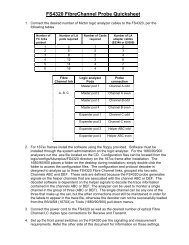
Test points<br />
All 68-pins of the interface are available to probe through clearly<br />
marked headers. In addition, two ground posts can be used to<br />
ground scope or high speed timing probes.<br />
Vcc<br />
Gnd<br />
C3<br />
C7<br />
Gnd<br />
CLKRUN#<br />
AD29<br />
AD26<br />
AD24<br />
AD22<br />
AD20<br />
CBE2#<br />
CLK<br />
Vcc<br />
GNT#<br />
PAR<br />
AD14<br />
AD11<br />
CBE0#<br />
AD5<br />
AD1<br />
GND<br />
J1<br />
GND<br />
RFU<br />
AD27<br />
AD25<br />
AD23<br />
AD21<br />
AD18<br />
IRDY#<br />
Vpp1<br />
INT#<br />
PERR#<br />
CBE1#<br />
AD12<br />
AD9<br />
AD7<br />
AD3<br />
AD0<br />
CD2#<br />
AD30<br />
STSCH<br />
CBE3#<br />
SERR#<br />
VS2<br />
AD17<br />
TRDY#<br />
Vcc<br />
STOP#<br />
RFU<br />
AD15<br />
VS1<br />
AD8<br />
AD6<br />
AD2<br />
GND<br />
J2<br />
GND<br />
AD31<br />
AD28<br />
AUDIO<br />
REQ#<br />
RST#<br />
AD19<br />
FRAME#<br />
VPP2<br />
DEVSEL#<br />
BLOCK#<br />
AD16<br />
AD13<br />
AD10<br />
RFU<br />
AD4<br />
-CD1<br />
R1<br />
R2<br />
R3<br />
R5<br />
R7<br />
R9<br />
R12<br />
R15<br />
R18<br />
R22<br />
R26<br />
R30<br />
R34<br />
R38<br />
R42<br />
SW1<br />
R10<br />
R13<br />
R16<br />
R20<br />
R24<br />
R28<br />
R32<br />
R36<br />
R40<br />
R44<br />
R47<br />
R50<br />
R53<br />
R56<br />
R58<br />
C5 C4<br />
V1<br />
JP1<br />
JP2<br />
J2A<br />
SW2<br />
D2<br />
5V<br />
PWR<br />
C6<br />
C8<br />
Gnd<br />
Connecting the logic<br />
analyzer to the<br />
<strong>FS2004</strong><br />
The following explains how to connect the logic analyzer to the<br />
<strong>FS2004</strong> for either state or timing analysis:<br />
1. Remove the probe tip assemblies from the logic<br />
analyzer cables.<br />
2. Plug the logic analyzer cables into the <strong>FS2004</strong> cable<br />
headers as shown in the appropriate table.<br />
10
For 16540/541 Logic Analyzers<br />
Logic Analyzer <strong>FS2004</strong> Comment<br />
16540 Pod 1 Header 3 J clock<br />
16541 Pod 1 Header 1<br />
16541 Pod 2 Header 2<br />
16541 Pod 3 Header 4<br />
All Other Logic Analyzers Except The 16540/541<br />
Logic Analyzer <strong>FS2004</strong> Comment<br />
POD 1 Header 1<br />
POD 2 Header 2<br />
POD 3 Header 3 L Clock (C3 on<br />
1680/90)<br />
POD 4 Header 4<br />
User Pins<br />
<strong>FS2004</strong> Header 4,2 and 1 each contains user defined pins.<br />
These pins are available to the user to connect whatever<br />
additional signals the users wishes to view along with the PC<br />
Card Cardbus signals. These pins are located on the logic<br />
analyzer interface module and clearly marked. The <strong>FS2004</strong><br />
configuration software will configure the user pins to appear as<br />
follows:<br />
• User1-User4 on POD 4 channels 12 thru 15.<br />
• User5 on POD 1 channel 16.<br />
• User6 on POD 2 channel 16.<br />
How to install a PC<br />
Card Cardbus add-in<br />
card into the <strong>FS2004</strong><br />
Using the PC Card Cardbus Preprocessor is relatively<br />
straightforward. The extender card is inserted into the desired<br />
slot in the host system. Then the PC Card Cardbus card under<br />
test is inserted into the card connector. Simply align the PC<br />
Card under test with the connector and gently push the module<br />
in until it is seated in the connector.<br />
11
Caution: Insertion and removal of the extender and PC card<br />
should be done with care. The PC Card's fragile connectors<br />
may be broken or bent if improper force is used. Both card<br />
and extender should be inserted straight without any lateral<br />
movement or force. Proper care and use of the extender card<br />
will insure years of trouble free operation.<br />
Operation of the PC<br />
Card Cardbus add-in<br />
card<br />
The nature of an extender card is that it extends the etch length<br />
of the bus. Due to the sensitivity of some PC Card Cardbus<br />
designs, extending the etch length can interfere with the PC<br />
Card Cardbus add-in card operation. Operation of the PC Card<br />
Cardbus add-in card when installed in the card edge extender<br />
connector is not guaranteed.<br />
If poor signal fidelity is causing a problem with the add-in card<br />
operation series terminating resistors can be installed on the<br />
extender/probe card in locations R1-R62.<br />
Series Termination<br />
Area<br />
A series termination area located between the test points and<br />
the card connector allows access to all PC Card Cardbus<br />
signals. A series of surface mount pads allows the user to add<br />
series resistors to any signal. The SMT pads are arranged as<br />
follows:<br />
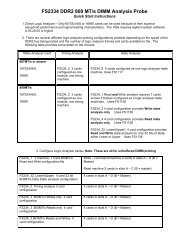
When shipped from the factory, the resistor pads are shorted<br />
with PCB traces. In order to insert series resistor, these traces<br />
must be cut prior to soldering the resistor to the board. Figure<br />
2.4-1 and 2.4-2 illustrate the termination areas located on both<br />
sides of the PCCextend board. Use this guide when making<br />
modifications to the board, since the silk-screen designations<br />
may be difficult to read.<br />
12
SW1<br />
CLKRUN# R1<br />
AD29 R2<br />
AD26 R3<br />
AD24 R5<br />
AD22 R7<br />
AD20 R9<br />
CBE2# R12<br />
GNT# R15<br />
R10<br />
R13<br />
R16<br />
R20<br />
R24<br />
R28<br />
R32<br />
R36<br />
CD2#<br />
AD30<br />
STSCHG<br />
CBE3#<br />
SERR#<br />
VS2<br />
AD17<br />
TRDY#<br />
INT#<br />
R18<br />
R40<br />
STOP#<br />
PAR<br />
R22<br />
R44<br />
RFU<br />
AD14<br />
R26<br />
R47<br />
AD15<br />
AD11<br />
R30<br />
R50<br />
VS1<br />
CBE0#<br />
R34<br />
R53<br />
AD8<br />
AD5<br />
R38<br />
R56<br />
AD6<br />
AD1<br />
R42<br />
R58<br />
AD2<br />
SW2<br />
Figure 2.4-1 Termination Area - Component Side<br />
AD31<br />
AD28<br />
AUDIO<br />
REQ#<br />
RST#<br />
AD19<br />
R19<br />
R23<br />
R27<br />
R31<br />
R35<br />
R39<br />
R4<br />
R6<br />
R8<br />
R11<br />
R14<br />
R17<br />
RFU<br />
AD27<br />
AD25<br />
AD23<br />
AD21<br />
AD18<br />
FRAME# R43<br />
R21 IRDY#<br />
VPP2 R46 R25 CLK<br />
DEVSEL#<br />
BLOCK#<br />
AD16<br />
R49<br />
R52<br />
R55<br />
AD13 R57<br />
AD10 R59<br />
RFU R60<br />
AD4 R61<br />
CD1# R62<br />
R29<br />
R33<br />
R37<br />
R41<br />
R45<br />
R48<br />
R51<br />
R54<br />
VPP1<br />
PERR#<br />
CBE1#<br />
AD12<br />
AD9<br />
AD7<br />
AD3<br />
AD0<br />
Figure 2.4-2 Termination Area - Solder Side<br />
13
Setting up the 166x,<br />
167x portables or the<br />
16500 Logic Analysis<br />
System<br />
The logic analyzer can be configured for PC Card Cardbus<br />
analysis by loading the PC Card Cardbus configuration file.<br />
Loading this file will load the PC Card Cardbus inverse<br />
assembler and configure your logic analyzer. To load the<br />
configuration and inverse assembler:<br />
1. Install the <strong>FS2004</strong> software flexible diskette in the disk<br />
drive of the logic analyzer.<br />
2. Configure the menu to “Load” the analyzer with the<br />
appropriate configuration file (see table below).<br />
Logic Analyzer<br />
File name for State<br />
Analysis<br />
File name for<br />
Timing<br />
Analysis<br />
16555, 167x CBUS_555 CBUS_555<br />
166x CBUS_660 CBUS_660<br />
16550 CBUS_550 CBUS_550<br />
1650 and<br />
16510<br />
CBUS_510S<br />
CBUS_510T<br />
3. Execute the load operation to load the file into the logic<br />
analyzer.<br />
For 1655x, 167x, 16540/541 and 166x REV2.0 (system software<br />
or later) users an enhanced inverse assembler is included on the<br />
preprocessor software diskette. After loading the above file, load<br />
the file IAPCIEXE. This will configure the STATE listing menu to<br />
include INVASM OPTIONS.<br />
Please note that 166x and 1655x, 167x users do not need to<br />
reload any files from the diskette when switching between<br />
state and timing analysis.<br />
Setting up the 167xx<br />
Logic Analysis System<br />
The 16600/16700 requires a special install procedure to install<br />
the PCI software. To accomplish this, insert the diskette labeled<br />
16700/16702 PCI Analysis Probe Install disk for the <strong>FS2004</strong><br />
into the 16600/700 diskette drive. From the SYSTEM<br />
ADMINISTRATION TOOLS select INSTALL under SOFTWARE.<br />
From the SOFTWARE INSTALL screen select the FLEXIBLE<br />
DISK and APPLY. Once the title appears, select it and then<br />
select INSTALL. This procedure does not need to be<br />
repeated. It only needs to be done the first time the PCI<br />
Analysis Probe is used.<br />
When the install is complete, load the appropriate configuration<br />
file from /logic/configs/<strong>FuturePlus</strong>/<strong>FS2004</strong> directory.<br />
Setting up the<br />
1680/90/900 Analyzer<br />
The 1680/90/900 Analyzer is a PC based application that<br />
requires a PC running the Windows OS or a 16900 frame.<br />
Before installing the protocol decoder for the PCI protocol on a<br />
PC you must install the Agilent logic analyzer software. Once<br />
the Agilent logic analyzer software is installed, you can install the<br />
14
<strong>FS2004</strong> protocol decoder by placing the CD-ROM disk into the<br />
CD-ROM drive of the target computer or Analyzer and executing<br />
the .exe setup program that is contained on the disk. The .exe<br />
setup file can be executed from within the File Explorer PC<br />
Utility. You must navigate to the .exe file on the CD-ROM disk<br />
and then double click the .exe file name from within the File<br />
Explorer navigation panel.<br />
The installation procedure does not need to be repeated. It<br />
only needs to be done the first time the Analysis Probe<br />
Adapter is used.<br />
1680/90/900<br />
Licensing<br />
The PCI Inverse Assembler is a licensed product that is locked<br />
to a single hard drive. The licensing process is performed by<br />
Agilent. There are instructions on this process on the SW<br />
Entitlement certificate provided with this product.<br />
Loading 1680/90/900<br />
configuration files<br />
and the General<br />
Purpose Probe<br />
feature<br />
When the software has been licensed you should be ready to<br />
load a configuration file. You can access the configuration files<br />
by clicking on the folder that was placed on the desktop. When<br />
you click on the folder it should open up to display all the<br />
configuration files to choose from. If you put your mouse cursor<br />
on the name of the file a description will appear telling you what<br />
the setup consists of, once you choose the configuration file that<br />
is appropriate for your configuration the 16900 operating system<br />
should execute. The protocol decoder automatically loads when<br />
the configuration file is loaded. If the decoder does not load, you<br />
may load it by selecting tools from the menu bar at the top of the<br />
screen and select the decoder from the list.<br />
Once you have loaded a configuration file on the 169xx machine<br />
you can find out how to attach the logic analyzer cables to the<br />
probe by going to the workspace and selecting Properties on the<br />
General Purpose Probe tool icon that appears before the logic<br />
analyzer icon. Once you click on the Properties box a new<br />
window will appear showing which analyzer pod attaches to<br />
which probe cable.<br />
The figure below may differ from your display; this is an example<br />
of how the display looks in general.<br />
15
Refer to the table below for a list of analyzers and corresponding<br />
configuration files.<br />
Configuration Files<br />
167xx Analyzer 169xx Analyzer State/Timing<br />
16550 CP204_1<br />
16555 CP204_2<br />
16717/8/9, 16750/1/2 CP204_3<br />
1680/90, 16750/1/2,<br />
1691x<br />
CP204_4.xml<br />
Offline Analysis<br />
Data that is saved on a 167xx analyzer in fast binary format, or<br />
16900 analyzer data saved as a *.ala file, can be imported into<br />
the 1680/90/900 environment for analysis. You can do offline<br />
analysis on a PC if you have the 1680/90/900 operating system<br />
installed on the PC, if you need this software please contact<br />
Agilent.<br />
Offline analysis allows a user to be able to analyze a trace offline<br />
at a PC so it frees up the analyzer for another person to use the<br />
analyzer to capture data.<br />
If you have already used the license that was included with your<br />
package on a 1680/90/900 analyzer and would like to have the<br />
16
offline analysis feature on a PC you may buy additional licenses,<br />
please contact <strong>FuturePlus</strong> sales department.<br />
In order to view decoded data offline, after installing the<br />
1680/90/900 operating system on a PC, you must install the<br />
<strong>FuturePlus</strong> software. Please follow the installation instructions<br />
for “Setting up 1680/90/900 analyzer”. Once the <strong>FuturePlus</strong><br />
software has been installed and licensed follow these steps to<br />
import the data and view it.<br />
From the desktop, double click on the Agilent logic analyzer icon.<br />
When the application comes up there will be a series of<br />
questions, answer the first question asking which startup option<br />
to use, select Continue Offline. On the analyzer type question,<br />
select cancel. When the application comes all the way up you<br />
should have a blank screen with a menu bar and tool bar at the<br />
top.<br />
For data from a 1680/90/900 analyzer, open the .ala file using<br />
the File, Open menu selections and browse to the desired .ala<br />
file.<br />
For data from a 16700, choose File -> Import from the menu bar,<br />
after selecting import select “yes” when it asks if the system is<br />
ready to import 16700 data.<br />
17
After clicking “next” you must browse for the fast binary data file<br />
you want to import. Once you have located the file and clicked<br />
start import, the data should appear in the listing.<br />
After the data has been imported you must load the protocol<br />
decoder before you will see any decoding. To load the decoder<br />
select Tools from the menu bar, when the drop down menu<br />
appears select Inverse Assembler, then choose the name of the<br />
decoder for your particular product. The figure below is a<br />
general picture; please choose the appropriate decoder for the<br />
trace you are working with.<br />
After the decoder has loaded, select Preferences if required,<br />
from the overview screen and set the preferences to their correct<br />
value in order to decode the trace properly. This is a general<br />
requirement, some decoders do not have preferences, if this is<br />
the case then no preference setting is necessary.<br />
18
The Format Menu<br />
The <strong>FS2004</strong> diskette sets up the format menu as shown in the<br />
following table (1655x, 167x,16510 and 166x, 1680/90). This<br />
format is the same for both Timing and State Analysis.<br />
Label<br />
Clk<br />
Inputs<br />
Pod 4 Pod 3 Pod 2 Pod 1<br />
STAT 9-0 14-0<br />
ADDR 15-0 15-0<br />
ADDR_B<br />
USER2_1 16 16<br />
INTD_A 14-11<br />
RESET 10<br />
C/B3_0 9-6<br />
DATA 15-0<br />
DEVSEL 5<br />
STOP 4<br />
LOCK 3<br />
PERR 2<br />
SERR 1<br />
PAR 0<br />
SD/SB0 5-6<br />
ACK/RQ 1-0<br />
IRDY 7<br />
19
Label<br />
Clk<br />
Inputs<br />
Pod 4 Pod 3 Pod 2 Pod 1<br />
FRAME 8<br />
TRDY 9<br />
PC Card<br />
Cardbus<br />
CLK<br />
L<br />
IDSEL 2<br />
GNT 3<br />
REQ 4<br />
CYCLE 9-7 9-4<br />
The STAT variable<br />
The STAT variable is used by the PC Card Cardbus inverse<br />
assembler to decode PC Card Cardbus bus transactions. It<br />
should not be changed or deleted from the format menu. The<br />
signals that make up the STAT variable are listed in the following<br />
table. The STAT variable can be useful to set up SYMBOLS<br />
since it contains all of the key PC Card Cardbus control and<br />
status signals.<br />
STAT Variable<br />
PC Card Cardbus Bus<br />
Signal Name<br />
Bit 24<br />
Bit 23<br />
Bit 22<br />
Bit 21<br />
Bit 20<br />
Bit 19<br />
Bit 18<br />
Bit 17<br />
Bit 16<br />
Bit 15<br />
Bit 14<br />
Bit 13<br />
Bit 12<br />
Bit 11<br />
TRDY#<br />
FRAME#<br />
IRDY#<br />
SDONE<br />
SB0#<br />
REQ#<br />
GNT#<br />
IDSEL<br />
ACK64#<br />
REQ64#<br />
INTD#<br />
INTC#<br />
INTB#<br />
INTA#<br />
20
STAT Variable<br />
PC Card Cardbus Bus<br />
Signal Name<br />
Bit 10<br />
Bit 9<br />
Bit 8<br />
Bit 7<br />
Bit 6<br />
Bit 5<br />
Bit 4<br />
Bit 3<br />
Bit 2<br />
Bit 1<br />
Bit 0<br />
RESET#<br />
C/BE3#<br />
C/BE2#<br />
C/BE1#<br />
C/BE0#<br />
DEVSE#L<br />
STOP#<br />
LOCK#<br />
PERR#<br />
SERR#<br />
PAR<br />
The ADDR, ADDR_B and<br />
DATA variables<br />
Using the 16517A/518A<br />
High Speed Timing Card<br />
The CYCLE variable<br />
The ADDR variable is AD[31-0] bits of the PC Card Cardbus<br />
bus. The DATA variable is a dummy variable that needs to be<br />
defined for the PC Card Cardbus inverse assembler. These<br />
variables should not be changed or deleted from the format<br />
Menu.<br />
The logic analyzer interface card can be removed for easy<br />
access to test points. These test points can be used to attach<br />
the flying lead set of the 16517A/518A high speed timing card.<br />
The PC Card Cardbus Preprocessor diskette has a configuration<br />
file named FS18PE that can be used as a starting point. Use this<br />
file and the stake pinout shown in the General Information<br />
chapter to connect the 16517A/518A to the <strong>FS2004</strong> stake pins.<br />
The CYCLE variable is made up of the following PC Card<br />
Cardbus signals: TRDY#, FRAME#, IRDY#, C/BE(3,0),<br />
DEVSEL# and STOP#. This variable has 30 symbols defined<br />
that can be used to help make triggering, timing analysis and<br />
pattern filtering easier. The following lists the bit pattern and the<br />
corresponding symbol.<br />
21
Symbol TRDY# FRAME# IRDY# C/BE(3:0) DEVSEL# STOP#<br />
INTACK 1 0 1 0000 1 1<br />
SPEC_CYC 1 0 1 0001 1 1<br />
I/O_RD 1 0 1 0010 1 1<br />
I/O_WR 1 0 1 0011 1 1<br />
RESVRD 1 0 1 0100 1 1<br />
RESVRD 1 0 1 0101 1 1<br />
MEM_RD 1 0 1 0110 1 1<br />
MEM_WR 1 0 1 0111 1 1<br />
RESRVD 1 0 1 1000 1 1<br />
RESRVD 1 0 1 1001 1 1<br />
CON_RD 1 0 1 1010 1 1<br />
CON_WR 1 0 1 1011 1 1<br />
MEMRDM 1 0 1 1100 1 1<br />
DAD_CY 1 0 1 1101 1 1<br />
MEMRDL 1 0 1 1110 1 1<br />
MEMWRI 1 0 1 1111 1 1<br />
IO_XACTION 1 0 1 001X 1 1<br />
MEM_XACTION 1 0 1 011X 1 1<br />
CONFIG_XACTION 1 0 1 101X 1 1<br />
ADD_CYCLE 1 0 1 XXXX 1 1<br />
DATA_XFER 0 0 0 XXXX 0 1<br />
WAIT_TARGET 1 X 0 XXXX 0 1<br />
WAIT_INITIATOR 0 X 1 XXXX 0 1<br />
DATA_FINALXFER 0 1 0 XXXX 0 1<br />
STOP_NOXFER X 0 1 XXXX 0 0<br />
STOP_DATAXFER 0 X 0 XXXX 0 0<br />
STOP_RETRY 1 1 0 XXXX 0 0<br />
TARGET_ABORT 1 0 1 XXXX 1 0<br />
22
Symbol TRDY# FRAME# IRDY# C/BE(3:0) DEVSEL# STOP#<br />
IDLE X 1 1 XXXX X X<br />
WAIT_NODEVSEL X X 0 XXXX 1 1<br />
WAIT_NODEVSEL/F_O X 0 0 XXXX 1 1<br />
23
State Analysis<br />
This chapter explains how to configure the <strong>FS2004</strong> to perform<br />
state analysis on your PC Card Cardbus target system. The<br />
configuration software sets up the format specification menu of<br />
the logic analyzer for compatibility with your PC Card Cardbus<br />
target system. The next chapter explains how to configure the<br />
<strong>FS2004</strong> to perform timing analysis.<br />
The <strong>FS2004</strong> preprocessor interface does not require that a PC<br />
Card Cardbus add-in card be installed in the <strong>FS2004</strong> card edge<br />
extender connector.<br />
Installation Quick<br />
Reference<br />
The following procedure describes the major steps required to<br />
perform state measurements with the <strong>FS2004</strong> module.<br />
1. Set the jumpers to the appropriate position on the<br />
<strong>FS2004</strong> module. See page 9 of this manual for details.<br />
2. After removing the probe tip assemblies, plug the logic<br />
analyzer cables into the preprocessor interface cable<br />
headers. See page 11 of this manual for details.<br />
3. Install the <strong>FS2004</strong> module into a slot in the target PC<br />
Card Cardbus Local bus.<br />
4. Load the logic analyzer configuration file by loading the<br />
appropriate file. See page 14 of this manual for details.<br />
24
Acquiring Data<br />
Touch RUN and, as soon as there is activity on the bus, the logic<br />
analyzer will begin to acquire data. The analyzer will continue to<br />
acquire data and will display the data when the analyzer memory<br />
is full, the trigger specification is TRUE or when you touch<br />
STOP.<br />
The logic analyzer will flash “Slow or Missing Clock” if it does not<br />
see the PC Card Cardbus signal CLK toggling.<br />
To capture PCI data, click the green arrow (run) button that is<br />
located on the tool bar at the top of the screen.<br />
Capture Data Figure on 1680/90/900<br />
25
The State Display<br />
Captured data is as shown in the following figure. The below<br />
figure displays the state listing after disassembly. The inverse<br />
assembler is constructed so the mnemonic output closely<br />
resembles the actual commands, status conditions, messages<br />
and phases specified in the PCI Local Bus specification.<br />
Symbols have also been defined to help aid in analysis. The<br />
non-disassembled state listing displays PC Card Cardbus bus<br />
mnemonics in addition to data. All data is displayed in hex. One<br />
exception is the decode of the address for a CONFIGURATION<br />
READ or a CONFIGURATION WRITE transaction. The<br />
Function (FUNC=) and Bus (BUS=) data is displayed in decimal.<br />
16500 Display<br />
26
16700 Display<br />
27
1680/90/900 Display<br />
28
Error Messages<br />
The following error messages are reported by the PC Card<br />
Cardbus inverse assembler.<br />
ERROR-NO DEVICE SELECTED<br />
This error is displayed during a non special cycle data phase<br />
when IRDY and TRDY are asserted and DEVSEL is not<br />
asserted.<br />
ERROR DEVSEL ASSERTED<br />
This error is displayed during a special cycle data phase if<br />
DEVSEL is asserted.<br />
SYSTEM ERROR<br />
This error is displayed anytime SERR# is asserted.<br />
1680/90/900 Errors:<br />
XXX input label could not be attached to.<br />
This error is displayed when the 1680/90 IA is being<br />
started and a failure occurs during the creation of an input<br />
label/column.<br />
XXX: input label invalid Min/Max parameters.<br />
This error is displayed during the creation of a<br />
label/column. The IA expects the label/column to fall<br />
within a min/max number of bits which has been violated.<br />
XXX: Failed to unattach from label<br />
This error is displayed when the 1680/90 IA is being exited<br />
and a failure occurs during the label/column destruction<br />
XXX: output label could not be created.<br />
This error is displayed when the 1680/90 IA is being<br />
started and a failure occurs when an output label/column<br />
is being constructed<br />
XXX: symbol could not created.<br />
This error is displayed when the 1680/90 IA is being<br />
started and a failure occurs when an output or input<br />
label/column symbol could not be created<br />
XXX: Could not save Label<br />
29
This error is displayed when the 1680/90 IA configuration file is<br />
being created and/or updated. The configuration data for the<br />
specified label could not be written to the file and thus will be<br />
lost.<br />
XXX: Could not load Label<br />
This error is displayed when the 1680/90 IA configuration<br />
file is being read. The configuration data for the specified<br />
label could not be read to the file and thus will be lost.<br />
INVASM OPTIONS<br />
INVASM OPTIONS is available with the following logic<br />
analyzers.<br />
• 16505A<br />
• 1655x, 167xA in a 16500B main frame<br />
• 16540/541 in a 16500B main frame<br />
• 166x series with 2.0 system software<br />
• 167xx series<br />
1680/90 does not implement an INVASM Options menu<br />
INVASM OPTIONS for the 165xxcan be invoked by selecting<br />
INVASM OPTIONS from the state listing display. The following<br />
selection will be displayed.<br />
INVASM OPTIONS for the 16700 family can be invoked by<br />
selecting INVASM from the state listing display and choose filter<br />
to display the color options. Below is a display taken from the<br />
16700 showing the filter options screen. To filter out any state<br />
just point to the state you want filtered out, and click on it. To<br />
turn back on simply click on the state again.<br />
30
16700 Invasm Filter Options<br />
Filtering<br />
The acquired state listing display can be modified to filter out any<br />
combination of the above transactions or cycles by selecting the<br />
show/suppress button to the right of the transaction list.<br />
For 16700 users, select filter under INVASM in the state listing.<br />
For 1680/90 users, select the Filter/Colorization pull down<br />
menus in the state listing and create a filter (downstream) tool.<br />
The 1680/90 IA allows filtering just like the 16700/702<br />
environments. You may filter on any label, when using the filter<br />
tags label you can select symbols to make choosing transactions<br />
easier. To create a filter, choose Tools->New->Filter/Colorize.<br />
Then fill in the information on the window that opens up. You<br />
must create a new filter for each item you want filtered. To<br />
remove filters that you no longer want, go to Tools->Overview<br />
and then choose the filter you want removed and click Delete.<br />
31
PC Mapper<br />
The PC Card Cardbus Preprocessor PC Mapper software is an<br />
enhanced version of the PC Card Cardbus Preprocessor inverse<br />
assembler and is for use only with PC Card Cardbus<br />
Preprocessor from <strong>FuturePlus</strong> <strong>Systems</strong> Corporation. The<br />
enhancement includes PC Card Cardbus I/O and memory<br />
address decode to indicate common PC access.<br />
Setting up the<br />
Analyzer from the<br />
diskette<br />
After the configuration file is loaded the PC Card Cardbus PC<br />
Mapper software can be loaded:<br />
1. Install the PC Card Cardbus Preprocessor software<br />
flexible diskette in the disk drive of the logic analyzer.<br />
2. Configure the menu to “Load” the analyzer with the<br />
appropriate file (see table).<br />
Logic Analyzer<br />
File name<br />
16500B mainframe with 16555,<br />
16550, 167x, or 16540/541 logic<br />
analyzer<br />
16500B mainframe with 16510<br />
16500A mainframe (all logic<br />
analyzer models)<br />
166x series (with REV 2.2 system<br />
software)<br />
165x logic analyzers<br />
IAPCIMXE<br />
IAPCIMX<br />
IAPCIMX<br />
IAPCIMXE<br />
IAPCIMX<br />
3. Execute the load operation to load the file into the logic<br />
analyzer.<br />
I<strong>FS2004</strong>E is the inverse assembler for all logic analyzers<br />
installed into the 16600/700 and is auto loaded when the<br />
configuration file is loaded.<br />
To select PC Mapper function on the 16700, select INVASM<br />
from the state listing display then select PREFERENCES it will<br />
come up with a box and there you can choose to turn on PC<br />
Mapper or suppress PC Mapper. The picture below displays PC<br />
Mapper function enabled on the 16700.<br />
32
Setting up the<br />
1680/90/900 for PC<br />
Mapper<br />
PC Mapper is currently not available on the 1680/90/900.<br />
Acquiring Data<br />
Data can be acquired by touching the RUN button. As soon as<br />
there is activity on the bus, the logic analyzer will begin to<br />
acquire data. The analyzer will continue to acquire data and will<br />
display the data when the analyzer memory is full, the trigger<br />
specification is TRUE or when you touch STOP.<br />
The logic analyzer will flash “Slow or Missing Clock” if the PC<br />
Card Cardbus Clock signal is not being detected by the logic<br />
analyzer. In this case, check the logic analyzer to PC Card<br />
Cardbus Preprocessor connection.<br />
The State Display<br />
with the PC Card<br />
Cardbus PC Mapper<br />
Captured data is as shown in the following figure. The first figure<br />
displays the state listing after disassembly. The PC Card<br />
Cardbus PC Mapper is constructed so the mnemonic output<br />
closely resembles the actual commands, status conditions,<br />
messages and phases specified in the PC Card Cardbus Local<br />
Bus specification. Symbols have also been defined to help aid in<br />
analysis. The non-disassembled state listing displays PC Card<br />
Cardbus bus mnemonics in addition to data. All data is displayed<br />
in hex. One exception is the decode of the address for a<br />
CONFIGURATION READ or a CONFIGURATION WRITE<br />
transaction. The Function (FUNC=) and Bus (BUS=) data is<br />
displayed in decimal.<br />
33
The above display data using the PC Card Cardbus Inverse<br />
Assembly software without the PC Card Cardbus PC Mapper<br />
functionality is shown as follows.<br />
The following listing shows the PC Mapper preference selected<br />
on the 16700.<br />
34
The following listing shows the PC Mapper preference<br />
suppressed on the 16700<br />
35
Error Messages<br />
The error messages reported by the PC Card Cardbus PC<br />
Mapper are the same as those reported with the standard non<br />
mapper version of the PC Card Cardbus Inverse Assembler.<br />
The acquired state listing display can be modified to filter out any<br />
combination of the above transactions or cycles by selecting the<br />
show/suppress button to the right of the transaction cycle list.<br />
PC Card Cardbus PC<br />
Mapping for memory<br />
transactions<br />
This section lists the addresses, the commands and the<br />
corresponding mapping done by the PC Card Cardbus PC<br />
Mapper software. For information on the standard PCI<br />
configuration register mapping please refer to the PCI Local Bus<br />
Specification Rev 2.1.<br />
Address bits 23-0<br />
greater than 0FFFFFH<br />
0FFFFF-0E0000H<br />
0DFFFF-0C0000H<br />
0BFFFF-0A0000H<br />
09FFFF-000400H<br />
0003FF-000000H<br />
PC Mapper output<br />
System Memory<br />
System BIOS<br />
ROM Scan<br />
Video Memory<br />
System Memory<br />
See Interrupt Vector Table<br />
36
Interrupt Vector<br />
Table<br />
Address bits<br />
23-0<br />
PC Mapper output<br />
0003C4H INT #F1-FF USER PROGRAMS<br />
000200H INT #80-F0 BASIC<br />
0001E0H INT #78-7F USER PROGRAMS<br />
0001DCH INT #77 IRQ15<br />
0001D8H INT #76 IRQ14<br />
0001D4H INT #75 IRQ13<br />
0001D0H INT #74 IRQ12<br />
0001CCH INT #73 IRQ11<br />
0001C8H INT #72 IRQ10<br />
0001C4H INT #71 IRQ9<br />
0001C0H INT #70 IRQ8<br />
0001A0H INT #68-6F RESERVED<br />
00019CH INT #67 EXP MEM MANG<br />
000180H INT #60-66 USER PROGRAMS<br />
00012CH INT #4B-5F RESERVED<br />
000128H INT #4A USER RTC ALARM<br />
00011CH INT #47-49 RESERVED<br />
000118H INT #46 HD DISK #1 PARAM<br />
000110H INT #44-45 RESERVED<br />
00010CH INT #43 VIDEO CHAR TABLE<br />
000108H INT #42 EGA BIOS<br />
000104H INT #41 HD DISK #0 PARAM<br />
000100H INT #40 FLOPPY DISK ISR<br />
000080H INT #20-3F RESERVED DOS<br />
00007CH INT #1F VIDEO CHAR TABLE<br />
000078H INT #1E FLOPPY PARAMS<br />
000074H INT #1D AVAILABLE<br />
000070H INT #1C AVAILABLE<br />
00006CH INT #1B KEYBOARD BREAK<br />
000068H INT #1A RTC ISR<br />
000064H INT #19 BOOSTRAP LOADER<br />
000060H INT #18 ROM BASIC<br />
00005CH INT #17 LPT PRINTER BIOS<br />
000058H INT #16 KEYBOARD BIOS<br />
000054H INT #15 SYS SERVICE BIOS<br />
000050H INT #14 SERIAL PORT BIOS<br />
00004CH INT #13 FLOPPY DISK BIOS<br />
000048H INT #12 MEM SIZE INT<br />
000044H INT #11 EQUIP LIST<br />
000040H INT #10 VIDEO BIOS<br />
00003CH INT #0F IRQ7 LPT1<br />
000038H INT #0E IRQ6 FLOPPY DISK<br />
000034H INT #0D IRQ5 LPT2<br />
000030H INT #0C IRQ4 SERIAL #1<br />
00002CH INT #0B IRQ3 SERIAL #2<br />
000028H INT #0A IRQ2 SLAVE INT<br />
000024H INT #09 KEYBOARD<br />
000020H INT #08 IRQ0 SYS TIMER<br />
00001CH INT #07 NUM COPROCESSOR<br />
000018H INT #06 INVALID OPCODE<br />
000014H INT #05 PRINT SCREEN<br />
000010H INT #04 OVERFLOW DETECT<br />
37
00000CH<br />
INT #03 BREAKPOINT TRACE<br />
38
Address bits<br />
23-0<br />
000008H<br />
000004H<br />
000000H<br />
PC Mapper output<br />
INT #02 NMI<br />
INT #01 SINGLE STEP<br />
INT #00 DIVIDE BY ZERO<br />
39
PC Card Cardbus PC<br />
Mapping - I/O<br />
Transactions<br />
Address bits<br />
23-0<br />
PC Mapper output<br />
0000H MSTR DMA CH 0<br />
0001H MSTR DMA CH 0<br />
0002H MSTR DMA CH 1<br />
0003H MSTR DMA CH 1<br />
0004H MSTR DMA CH 2<br />
0005H MSTR DMA CH 2<br />
0006H MSTR DMA CH 3<br />
0007H MSTR DMA CH 3<br />
0008H MSTR DMA STAT REG<br />
0009H UNKNOWN IO DEVICE<br />
000AH MSTR DMA MASK REG<br />
000BH MSTR DMA MODE REG<br />
000CH MSTR DMA CLR BYTE PTR<br />
000DH MSTR DMA MSTR CLEAR<br />
000EH MSTR DMA CLEAR MASK<br />
000FH MSTR DMA WRT MASK<br />
0018H MSTR DMA CH EXT FUNCT REG<br />
001AH MSTR DMA EXT FUNCT<br />
0020H MSTR INT REQ REG<br />
0021H MSTR INT REQ REG2<br />
0040H INTERVAL TIMER TIMER 0<br />
0042H INTERVAL TIMER SPKR TIMER<br />
0043H INTRVAL TIMER #1 CNTRL<br />
0044H INTERVL TIMER #2 WATCHDOG<br />
0047H INTERVAL TIMER #2 CNTRL<br />
0060H KEYBOARD/MOUSE DATA PORT<br />
0061H SYSTEM CONTOL PORT B<br />
0064H KEYBOARD/MOUSE CMD PORT<br />
0070H RTC/CMOS RAM ADDR PORT<br />
0071H RTC/CMOS RAM DATA PORT<br />
0074H EXT CMOS RAM ADDR PORT<br />
0075H EXT CMOS RAM ADDR PORT<br />
0076H EXT CMOS RAM DATA PORT<br />
0081H CH 2 DMA PAGE REGISTER<br />
0082H CH 3 DMA PAGE REGISTER<br />
0083H CH 1 DMA PAGE REGISTER<br />
0087H CH 0 DMA PAGE REGISTER<br />
0089H CH 6 DMA PAGE REGISTER<br />
008AH CH 7 DMA PAGE REGISTER<br />
008BH CH 5 DMA PAGE REGISTER<br />
008FH CH 4 DMA PAGE REGISTER<br />
0090H ARB CNTRL POINT REG<br />
0091H FEEDBACK REG<br />
0092H SYSTEM CONTROL PORT A<br />
0094H SYS SETUP/CARD ENABLE REG<br />
0096H ADAPTOR SETUP/ENABLE REG<br />
00A0H SLAVE INTERRUPT CNTRLR<br />
00A1H SLAVE INTERRUPT CNTRLR<br />
00C0H SLAVE DMA CH4 MEM ADDR<br />
00C2H SLAVE DMA CH4 TRANS COUNT<br />
00C4H SLAVE DMA CH5 MEM ADDR<br />
00C6H SLAVE DMA CH5 TRANS COUNT<br />
40
00C8H<br />
Address bits<br />
23-0<br />
SLAVE DMA CH6 MEM ADDR<br />
PC Mapper output<br />
00CAH SLV DMA CH6 TRANS COUNT<br />
00CCH SLAVE DMA CH7 MEM ADDR<br />
00CEH SLAVE DMA CH7 TRANS COUNT<br />
00D0H SLV DMA STATUS REG CH 4-7<br />
00D4H SLV DMA MASK REG CH 4-7<br />
00D6H SLAVE DMA MODE REG CH 4-7<br />
00D8H SLAVE DMA CLEAR BYTE PNTR<br />
00DAH SLAVE DMA MASTER CLEAR<br />
00DCH SLV DMA CLR MASK CH 4-7<br />
00DEH SLAVE DMA WRITE MASK REG<br />
00E0H IBM MODELS - ENCODE REG<br />
00E1H IBM MODELS - ENCODE REG<br />
00F1H NUMERIC COPROCESSOR RESET<br />
00F8H NUMERIC COPROCESSOR PORT<br />
00F9H NUMERIC COPROCESSOR PORT<br />
00FAH NUMERIC COPROCESSOR PORT<br />
00FBH NUMERIC COPROCESSOR PORT<br />
00FCH NUMERIC COPROCESSOR PORT<br />
0100H ADAPTER CARD POS REG 0<br />
0101H ADAPTER CARD POS REG 1<br />
0102H SYS BD/ADP CD POS REG 2<br />
0103H SYS BD/ADP CD POS REG 3<br />
0104H ADAPTER CARD POS REG 4<br />
0105H ADAPTER CARD POS REG 5<br />
0106H ADAPTER CARD POS REG 6<br />
0107H ADAPTER CARD POS REG 6<br />
0278H PARALLEL PORT 3 DATA PORT<br />
0279H PARALLEL PORT 3 STAT PORT<br />
027AH PARALLEL PORT 3 CMD PORT<br />
02F8H SERIAL PORT 2 XMIT/REC<br />
02F9H SER PORT 2 DIV LATCH/INT<br />
02FAH SERIAL PORT 2 INT ID REG<br />
02FBH SERIAL PORT 2 CNTRL REG<br />
02FDH SERIAL PORT 2 MODEM CNTRL<br />
02FEH SERIAL PORT 2 MODEM STAT<br />
02FFH SERIAL PORT 2 SCRTCH REG<br />
0378H PARALLEL PORT 2 DATA PORT<br />
0379H PARALLEL PORT 2 STAT PORT<br />
037AH PARALLEL PORT 2 CMD PORT<br />
03B4H VGA CRT CNTRLR ADDR REG<br />
03B5H VGA CRT CNTRLR DATA REG<br />
03BAH VGA STAT 1/FEATURE CNTRL<br />
03BCH PARALLEL PORT 1 DATA PORT<br />
03BDH PARALLEL PORT 1 STAT PORT<br />
03BEH PARALLEL PORT 1 CMD PORT<br />
03C0H VGA ATTRIBUTE CNTRLR ADDR<br />
03C1H VGA ATTRIBUTE CNTRLR DATA<br />
03C2H VGA OUTPUT/STAT REG<br />
03C3H VGA VIDEO SUBSYSTM ENABLE<br />
03C4H VGA SEQUENCER ADDR REG<br />
03C5H VGA SEQUENCER DATA REG<br />
41
03C6H<br />
03C7H<br />
VIDEO DAC PEL MASK<br />
VIDEO DAC PAL ADDR/STAT<br />
Address bits<br />
23-0<br />
03C8H<br />
03C9H<br />
03CAH<br />
03CCH<br />
03CEH<br />
03CFH<br />
03D4H<br />
03D5H<br />
03DAH<br />
03F0H<br />
03F1H<br />
03F2H<br />
03F4H<br />
03F5H<br />
03F7H<br />
03F8H<br />
03F9H<br />
03FAH<br />
03FBH<br />
03FCH<br />
03FDH<br />
03FEH<br />
03FFH<br />
0680H<br />
PC Mapper output<br />
VIDEO DAC PAL ADDR/WRITE<br />
VIDEO DAC PALETTE DATA<br />
VGA FEATURE CONTOL REG<br />
VGA MISC OUTPUT REG<br />
VGA GRAPHICS CNTRLR ADDR<br />
VGA GRAPHICS CNTRLR ADDR<br />
VGA CRT CNTRLR ADDR REG<br />
VGA GRAPHICS CNTRLR DATA<br />
VGA COLOR STAT 1/FEATURE<br />
FLOPPY STATUS REG A<br />
FLOPPY STATUS REG B<br />
FLOPPY DIGITAL OUTPUT REG<br />
FLOPPY DISK CNTRLR STAT<br />
FLOPPY DISK CNTRLR DATA<br />
FLOPPY CONFIG CONTROL REG<br />
SERIAL PORT 1 XMIT/RCV BUF<br />
SER PORT 1 DIV LATCH/INT<br />
SERIAL PORT 1 INT ID/FIFO<br />
SERIAL PORT 1 LINE CNTRL<br />
SERIAL PORT 1 MODEM CNTRL<br />
SERIAL PORT 1 STAT REG<br />
SERIAL PORT 1 MODEM STAT<br />
SERIAL PORT 1 SCRATCH REG<br />
MANUFCTURNG CHCKPNT PORT<br />
42
Timing Analysis<br />
Installation Quick<br />
Reference<br />
Since the <strong>FS2004</strong> interface contains only passive matching<br />
terminators it introduces negligible skew to the PC Card Cardbus<br />
Local Bus signals.<br />
The following procedure describes the major steps required to<br />
perform timing analysis measurements with the <strong>FS2004</strong> module.<br />
1. Set the jumpers to the appropriate position on the<br />
<strong>FS2004</strong> module. See page 9 of this manual for details.<br />
2. After removing the probe tip assemblies, plug the logic<br />
analyzer cables into the logic analyzer interface module<br />
headers. See page 10 of this manual for details.<br />
3. Install the <strong>FS2004</strong> module into a slot in the target PC<br />
Card Cardbus Local bus.<br />
Acquiring Data<br />
4. Load the logic analyzer configuration file by loading the<br />
appropriate file from the preprocessor interface diskette.<br />
See page 14 of this manual for details.<br />
Touch RUN and, as soon as there is activity on the bus, the logic<br />
analyzer will begin to acquire data. The analyzer will continue to<br />
acquire data and will display the data when the analyzer memory<br />
is full, the trigger specification is TRUE or when you touch<br />
STOP.<br />
The logic analyzer will flash “Waiting for Trigger” if the trigger<br />
specification has not been met.<br />
43
The Waveform<br />
Display<br />
Captured data is displayed as shown in the following figure.<br />
Timing Analysis<br />
using the<br />
16517A/518A High<br />
speed timing card<br />
Removing the logic analyzer interface module will give access to<br />
the test point area. This is a convenient way of attaching the<br />
high speed timing card. Using the 16517A/518A high speed<br />
timing card, measurements of 250ps can be made.<br />
44
General Information<br />
Characteristics<br />
Preprocessor Interface<br />
Compatibility<br />
Card Edge Extender<br />
Connector<br />
Standards Supported<br />
Power Requirements<br />
Logic Analyzer Required<br />
Number of Probes Used<br />
Minimum Clock Period<br />
(State)<br />
Signal loading<br />
This chapter provides additional reference information including<br />
the characteristics and signal connections for the <strong>FS2004</strong><br />
module.<br />
The following operating characteristics are not specifications, but<br />
are typical operating characteristics for the <strong>FS2004</strong> module.<br />
32 bit PC Card Cardbus Local bus accepting the Type 1 form<br />
factor. All PC Card Cardbus local bus ground pins are connected<br />
to the ground plane of the Extender/Probe card and the logic<br />
analyzer interface module.<br />
This connector is a Type 1 connector. All of the signals from the<br />
PC Card Cardbus bus are routed to the extender connector.<br />
The PCI Local Bus Specification Revision 2.1 and PC Card ‘95<br />
standard.<br />
The <strong>FS2004</strong> preprocessor draws a small amount of power from<br />
the PC Card Cardbus target for the LED. The PC Card Cardbus<br />
add-in card installed in the <strong>FS2004</strong> can draw power from the +/-<br />
12V, 3.3V and the 5V pins as if it were installed without the<br />
<strong>FS2004</strong>.<br />
166x, 1661, 1662, 1655x, 167x, 16510, 1650, 16540/541,<br />
167xx, 1680/90/900. 1675x, 1695x, 1691x.<br />
The preprocessor interface uses 4 cable headers.<br />
Not limited by the preprocessor interface logic. Clocking is<br />
specified by the logic analyzer.<br />
The <strong>FS2004</strong> Preprocessor logic presents one 10pf/90k ohm load<br />
on each PC Card Cardbus bus signal. The card edge extender<br />
connector adds an addition 2pf. If stake pins are installed as test<br />
points they add 1pf. If the test points are configured with an<br />
additional PC Card Cardbus connector this connector adds<br />
approximately 2pf. The etch and associated via’s add<br />
approximately 1pf of additional capacitance.<br />
Operations<br />
All PC Card Cardbus operations supported by the hardware and<br />
the inverse assembler.<br />
45
Environmental<br />
Temperature<br />
Altitude<br />
Operating:0 to 55 degrees C (+32 to +131 degrees F)<br />
Non operating:-40 to +75 degrees C (-40 to +167 degrees F)<br />
Operating: 4,6000m (15,000 ft)<br />
Non operating: 15,3000m (50,000 ft)<br />
Humidity<br />
Testing and<br />
Troubleshooting<br />
Servicing<br />
Up to 90% non condensing. Avoid sudden, extreme temperature<br />
changes which would cause condensation on the <strong>FS2004</strong><br />
module.<br />
There are no automatic performance tests or adjustments for the<br />
<strong>FS2004</strong> module. If a failure is suspected in the <strong>FS2004</strong> module<br />
contact the factory or your <strong>FuturePlus</strong> <strong>Systems</strong> authorized<br />
distributor.<br />
The repair strategy for the <strong>FS2004</strong> is module replacement.<br />
However, if parts of the <strong>FS2004</strong> module are damaged or lost<br />
contact the factory for a list of replacement parts.<br />
46
Signal Connections<br />
Test Point pinout<br />
The <strong>FS2004</strong> contains 4, forty pin headers for connection to<br />
Agilent logic analyzers and test points for scope or flying lead<br />
logic analyzer connection.<br />
The <strong>FS2004</strong> test points can be accessed by removing the logic<br />
analyzer interface module and attaching directly to the test<br />
points. The signal names are clearly marked on the etch.<br />
The Preprocessor<br />
interface pinout<br />
The logic analyzer interface module attaches to the test pints on<br />
the probe/extender card. This then attaches to the logic<br />
analyzer thru 40 pin headers. The below figure displays how<br />
pins of the 40 pin cable headers are numbered.<br />
39 37 35 33 31 29 27 25 23 21 19 17 15 13 11 9 7 5 3 1<br />
40 38 36 34 32 30 28 26 24 22 20 18 16 14 12 10 8 6 4 2<br />
The following tables list the <strong>FS2004</strong> cable headers and the<br />
corresponding PC Card Cardbus signals after these signals<br />
have been terminated by the 90K ohm/10pf terminators.<br />
47
Preprocessor<br />
Cable Header and<br />
Pin number<br />
Logic Analyzer<br />
channel number<br />
PC Card Cardbus<br />
Signal name<br />
Header 1 pin 3 CLK/16 USER5<br />
5 no connect<br />
7 15 AD15<br />
9 14 AD14<br />
11 13 AD13<br />
13 12 AD12<br />
15 11 AD11<br />
17 10 AD10<br />
19 9 AD09<br />
21 8 AD08<br />
23 7 AD07<br />
25 6 AD06<br />
27 5 AD05<br />
29 4 AD04<br />
31 3 AD03<br />
33 2 AD02<br />
35 1 AD01<br />
37 0 AD00<br />
48
Preprocessor<br />
Cable Header and<br />
Pin number<br />
Logic Analyzer<br />
channel number<br />
PC Card Cardbus<br />
Signal name<br />
Header 2 pin 3 CLK/16 USER6<br />
5 no connect<br />
7 15 AD31<br />
9 14 AD30<br />
11 13 AD29<br />
13 12 AD28<br />
15 11 AD27<br />
17 10 AD26<br />
19 9 AD25<br />
21 8 AD24<br />
23 7 AD23<br />
25 6 AD22<br />
27 5 AD21<br />
29 4 AD20<br />
31 3 AD19<br />
33 2 AD18<br />
35 1 AD17<br />
37 0 AD16<br />
49
Preprocessor<br />
Cable Header and<br />
Pin number<br />
Logic Analyzer<br />
channel number<br />
PC Card Cardbus<br />
Signal name<br />
Header 3 pin 3 CLK/16 PCI Clock here<br />
for 166x/550<br />
and 16510<br />
State analysis.<br />
5 no connect<br />
7 15 PCI Clock<br />
16510 Timing<br />
analysis only.<br />
9 14 CCLKRUN#<br />
11 13 CCD2#<br />
13 12 CCD1#<br />
15 11 CINT#<br />
17 10 RST#<br />
19 9 C/BE3#<br />
21 8 C/BE2#<br />
23 7 C/BE1#<br />
25 6 C/BE0#<br />
27 5 DEVSEL#<br />
29 4 STOP#<br />
31 3 LOCK#<br />
33 2 PERR#<br />
35 1 SERR#<br />
37 0 PAR<br />
50
Preprocessor<br />
Cable Header and<br />
Pin number<br />
Logic Analyzer<br />
channel number<br />
PC Card Cardbus<br />
Signal name<br />
Logic Analyzer Interface<br />
module<br />
Header 4 pin 3 CLK/16<br />
5 no connect<br />
7 15 USER4<br />
9 14 USER3<br />
11 13 USER2<br />
13 12 USER1<br />
15 11 VS2<br />
17 10 VS1<br />
19 9 TRDY#<br />
21 8 FRAME#<br />
23 7 IRDY#<br />
25 6 CSTSCHG<br />
27 5 CAUDIO<br />
29 4 REQ#<br />
31 3 GNT#<br />
33 2 RFU3<br />
35 1 RFU2<br />
37 0 RFU1<br />
51
<strong>FS2004</strong> Mechanical<br />
drawings<br />
Logic Analyzer Interface<br />
module<br />
52
53<br />
CLKRUN#<br />
AD29<br />
AD26<br />
AD24<br />
AD22<br />
AD20<br />
CBE2#<br />
CLK<br />
Vcc<br />
GNT#<br />
PAR<br />
AD14<br />
AD11<br />
CBE0#<br />
AD5<br />
AD1<br />
GND<br />
GND<br />
RFU<br />
AD27<br />
AD25<br />
AD23<br />
AD21<br />
AD18<br />
IRDY#<br />
Vpp1<br />
INT#<br />
PERR#<br />
CBE1#<br />
AD12<br />
AD9<br />
AD7<br />
AD3<br />
AD0<br />
CD2#<br />
AD30<br />
STSCH<br />
CBE3#<br />
SERR#<br />
VS2<br />
AD17<br />
TRDY#<br />
Vcc<br />
STOP#<br />
RFU<br />
AD15<br />
VS1<br />
AD8<br />
AD6<br />
AD2<br />
GND<br />
GND<br />
AD31<br />
AD28<br />
AUDIO<br />
REQ#<br />
RST#<br />
AD19<br />
FRAME#<br />
VPP2<br />
DEVSEL#<br />
BLOCK#<br />
AD16<br />
AD13<br />
AD10<br />
RFU<br />
AD4<br />
-CD1<br />
PWR<br />
5V<br />
SW1<br />
Vcc Gnd<br />
Gnd<br />
D2 C8<br />
C7<br />
C6<br />
C4<br />
C3<br />
V1<br />
J2A<br />
J1 J2<br />
JP1<br />
JP2<br />
SW2<br />
C5<br />
Gnd<br />
R1<br />
R2<br />
R3<br />
R5<br />
R7<br />
R9<br />
R12<br />
R15<br />
R18<br />
R22<br />
R26<br />
R30<br />
R34<br />
R38<br />
R42<br />
R10<br />
R13<br />
R16<br />
R20<br />
R24<br />
R28<br />
R32<br />
R36<br />
R40<br />
R44<br />
R47<br />
R50<br />
R53<br />
R56<br />
R58<br />
CARDBUS<br />
PCCextend<br />
Probe/Extender module