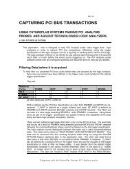
FS2004 Users Manual - FuturePlus Systems
FS2004 Users Manual - FuturePlus Systems
FS2004 Users Manual - FuturePlus Systems

You also want an ePaper? Increase the reach of your titles
YUMPU automatically turns print PDFs into web optimized ePapers that Google loves.
Caution: Insertion and removal of the extender and PC card<br />
should be done with care. The PC Card's fragile connectors<br />
may be broken or bent if improper force is used. Both card<br />
and extender should be inserted straight without any lateral<br />
movement or force. Proper care and use of the extender card<br />
will insure years of trouble free operation.<br />
Operation of the PC<br />
Card Cardbus add-in<br />
card<br />
The nature of an extender card is that it extends the etch length<br />
of the bus. Due to the sensitivity of some PC Card Cardbus<br />
designs, extending the etch length can interfere with the PC<br />
Card Cardbus add-in card operation. Operation of the PC Card<br />
Cardbus add-in card when installed in the card edge extender<br />
connector is not guaranteed.<br />
If poor signal fidelity is causing a problem with the add-in card<br />
operation series terminating resistors can be installed on the<br />
extender/probe card in locations R1-R62.<br />
Series Termination<br />
Area<br />
A series termination area located between the test points and<br />
the card connector allows access to all PC Card Cardbus<br />
signals. A series of surface mount pads allows the user to add<br />
series resistors to any signal. The SMT pads are arranged as<br />
follows:<br />
When shipped from the factory, the resistor pads are shorted<br />
with PCB traces. In order to insert series resistor, these traces<br />
must be cut prior to soldering the resistor to the board. Figure<br />
2.4-1 and 2.4-2 illustrate the termination areas located on both<br />
sides of the PCCextend board. Use this guide when making<br />
modifications to the board, since the silk-screen designations<br />
may be difficult to read.<br />
12