FS2004 Users Manual - FuturePlus Systems
FS2004 Users Manual - FuturePlus Systems
FS2004 Users Manual - FuturePlus Systems

You also want an ePaper? Increase the reach of your titles
YUMPU automatically turns print PDFs into web optimized ePapers that Google loves.
Analyzing the PC Card<br />
Cardbus Local Bus<br />
Duplicating the 167xx<br />
Logic Analyzer<br />
Master Diskette<br />
Accessories<br />
Supplied<br />
Minimum Equipment<br />
Required<br />
Signal Naming<br />
Conventions<br />
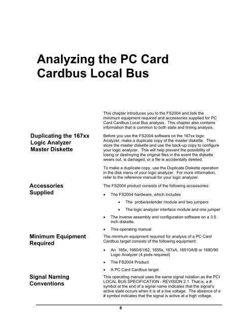
This chapter introduces you to the <strong>FS2004</strong> and lists the<br />
minimum equipment required and accessories supplied for PC<br />
Card Cardbus Local Bus analysis. This chapter also contains<br />
information that is common to both state and timing analysis.<br />
Before you use the <strong>FS2004</strong> software on the 167xx logic<br />
Analyzer, make a duplicate copy of the master diskette. Then<br />
store the master diskette and use the back-up copy to configure<br />
your logic analyzer. This will help prevent the possibility of<br />
losing or destroying the original files in the event the diskette<br />
wears out, is damaged, or a file is accidentally deleted.<br />
To make a duplicate copy, use the Duplicate Diskette operation<br />
in the disk menu of your logic analyzer. For more information,<br />
refer to the reference manual for your logic analyzer.<br />
The <strong>FS2004</strong> product consists of the following accessories:<br />
• The <strong>FS2004</strong> hardware, which includes<br />
• The probe/extender module and two jumpers<br />
• The logic analyzer interface module and one jumper<br />
• The inverse assembly and configuration software on a 3.5<br />
inch diskette.<br />
• This operating manual<br />
The minimum equipment required for analysis of a PC Card<br />
Cardbus target consists of the following equipment:<br />
• An 165x, 1660/61/62, 1655x, 167xA, 16510A/B or 1680/90<br />
Logic Analyzer (4 pods required)<br />
• The <strong>FS2004</strong> Product<br />
• A PC Card Cardbus target<br />
This operating manual uses the same signal notation as the PCI<br />
LOCAL BUS SPECIFICATION - REVISION 2.1. That is, a #<br />
symbol at the end of a signal name indicates that the signal’s<br />
active state occurs when it is at a low voltage. The absence of a<br />
# symbol indicates that the signal is active at a high voltage.<br />
8