Manual - FuturePlus Systems
Manual - FuturePlus Systems
Manual - FuturePlus Systems

Create successful ePaper yourself
Turn your PDF publications into a flip-book with our unique Google optimized e-Paper software.
<strong>FuturePlus</strong> <strong>Systems</strong> CorporationFibre Channel Analysis ProbeFS4300Users <strong>Manual</strong>For Agilent Technologies Logic AnalyzersRevision 1.3<strong>FuturePlus</strong> is a registered trademark of <strong>FuturePlus</strong> <strong>Systems</strong> Corporation.Copyright 1999 <strong>FuturePlus</strong> <strong>Systems</strong> Corporation.
USERS MANUAL 1HOW TO REACH US 5PRODUCT WARRANTY 6Limitation of warranty 6Exclusive Remedies 6Assistance 6INTRODUCTION 7How to Use This <strong>Manual</strong> 7Document Notation 7ANALYZING FIBRE CHANNEL 8Duplicating the Master Diskette 8Accessories Supplied 8Minimum Equipment Required 9Theory of Operation 9LED Indicators 10IDLE LED 10PRIM LED 10SOF LED 10RX OK LED 10TX OK LED 11Comma Detect LED 11SIG OK LED 11RETIME OK LED 11The interface to the Logic Analyzer 11Setting up the 16600/16700 Analyzer 11Setting up Analyzers installed in the 16500 mainframe and the portables 11Setting up the 16505A Prototype Analyzer 13Powering the Analysis Probe 13Connecting to the Analysis Probe 132
One Channel Only 14Two Channels using Two separate Logic Analyzer Cards 14Installing the Analysis Probe 15SMA Signal Levels 17Logic Analyzer Configuration Files 17The Inverse Assembler 19The Format Menu 19The STAT variable 19The ADDR and DATA variables 19Other Labels and Symbols 19STATE ANALYSIS 22Installation Quick Reference 22Setting Configuration Switches 22Disabling the GBIC Transmitter 22Selecting Fibre Channel Source 22Selecting Feed-Through or Loop-Back 23Data Re-Timing 23Enabling Clock Suppression 23Mode Switch 24Acquiring Data 24The State Listing Display 24Presentation of Information 24Inverse Assembler Modes of Operation 25Selecting Display Mode on the 16500A/B/C 25Selecting Display Mode on the 16700 25Full Mode 26Summary Mode 29Configuration Mode 32Using Symbols to Trigger in State Mode. 33Triggering on a Frame Type & fields within a frame. 33Triggering on a Destination ID or Source ID 34<strong>Manual</strong> Trigger 34Qualifying Storage of Packets 34Duplicate primitive and data filtering 35Inter-frame Primitive Filtering 35Filtering Data Payload 383
The 20s Label 38Error Messages 38Post Processing Filters 39GENERAL INFORMATION 41Characteristics 41Analysis Probe Interface Compatibility 41Power Requirements 41Logic Analyzer Required 41Number of Probes Used 41Maximum Speed 41Environmental Temperature 41Altitude 41Humidity 41Testing and Troubleshooting 41Servicing 41APPENDIX A: FORMAT DEFINITIONS 424
How to reach usFor Technical Support:<strong>FuturePlus</strong> <strong>Systems</strong> Corporation36 Olde English RoadBedford NH 03110TEL: 603-471-2734FAX: 603-471-2738On the web http://www.futureplus.comFor Sales and Marketing Support:<strong>FuturePlus</strong> <strong>Systems</strong> CorporationTEL: 719-278-3540FAX: 719-278-9586On the web http://www.futureplus.com<strong>FuturePlus</strong> <strong>Systems</strong> has technical salesrepresentatives in several major countries. For an upto date listing please seehttp://www.futureplus.com/contact.html.Agilent Technologies is also an authorized reseller ofmany <strong>FuturePlus</strong> products. Contact any AgilentTechnologies sales office for details..5
Product WarrantyThis <strong>FuturePlus</strong> <strong>Systems</strong> product has a warranty against defectsin material and workmanship for a period of 1 year from the dateof shipment. During the warranty period, <strong>FuturePlus</strong> <strong>Systems</strong>will, at its option, either replace or repair products proven to bedefective. For warranty service or repair, this product must bereturned to the factory.For products returned to <strong>FuturePlus</strong> <strong>Systems</strong> for warrantyservice, the Buyer shall prepay shipping charges to <strong>FuturePlus</strong><strong>Systems</strong> and <strong>FuturePlus</strong> <strong>Systems</strong> shall pay shipping charges toreturn the product to the Buyer. However, the Buyer shall pay allshipping charges, duties, and taxes for products returned to<strong>FuturePlus</strong> <strong>Systems</strong> from another country.Limitation ofwarrantyExclusive RemediesAssistance<strong>FuturePlus</strong> <strong>Systems</strong> warrants that its software and hardwaredesignated by <strong>FuturePlus</strong> <strong>Systems</strong> for use with an instrumentwill execute its programming instructions when properly installedon that instrument. <strong>FuturePlus</strong> <strong>Systems</strong> does not warrant thatthe operation of the hardware or software will be uninterrupted orerror-free.The foregoing warranty shall not apply to defects resulting fromimproper or inadequate maintenance by the Buyer, Buyersuppliedsoftware or interfacing, unauthorized modification ormisuse, operation outside of the environmental specifications forthe product, or improper site preparation or maintenance. NOOTHER WARRANTY IS EXPRESSED OR IMPLIED.FUTUREPLUS SYSTEMS SPECIFICALLY DISCLAIMS THEIMPLIED WARRANTIES OF MERCHANTABILITY ANDFITNESS FOR A PARTICULAR PURPOSE.THE REMEDIES PROVIDED HEREIN ARE BUYER’S SOLEAND EXCLUSIVE REMEDIES. FUTUREPLUS SYSTEMSSHALL NOT BE LIABLE FOR ANY DIRECT, INDIRECT,SPECIAL, INCIDENTAL, OR CONSEQUENTIAL DAMAGES,WHETHER BASED ON CONTRACT, TORT, OR ANY OTHERLEGAL THEORY.Product maintenance agreements and other customerassistance agreements are available for <strong>FuturePlus</strong> <strong>Systems</strong>products. For assistance, contact the factory.6
IntroductionThe FS4300 Fibre Channel Analysis Probe provides a completeinterface between a Fibre Channel link and Agilent LogicAnalyzers. Connection to the Fibre Channel is made via industrystandard GBICs (not supplied). The on board logic translatestransaction packets into a format that can be interpreted by theFS4300 software running on a Logic Analysis System. TheFS4300 Analysis Probe is a monitor that does not generatetransactions on the Fibre Channel.How to Use This<strong>Manual</strong>The configuration software on the diskette sets up the format,configuration and trigger specification menu of the logic analyzerfor compatibility with a Fibre Channel link. When the stateconfiguration file is loaded, an inverse assembler is also loadedwhich decodes Fibre Channel transactions into easy to readmnemonics.This manual is organized to help you quickly find the informationyou need.• The chapter Analyzing Fibre Channel introduces you to theFibre Channel Analysis Probe and lists the minimumequipment required and accessories supplied for FibreChannel analysis.• The State Analysis chapter explains how to configure theFibre Channel Analysis Probe to perform state analysis on aFibre Channel link.• The General Information chapter provides some generalinformation including the operating characteristics for theFibre Channel Analysis Probe module.Document NotationThe term “word” is used to refer to a 32 bit (4 byte) unit of data.7
Analyzing Fibre ChannelDuplicating theMaster DisketteThis chapter introduces you to the Fibre Channel Analysis Probeand lists the minimum equipment required and accessoriessupplied for Fibre Channel analysis.Users of the 16500 Logic Analysis System should make aduplicate copy of the master diskette before using the FibreChannel Analysis Probe software. Then store the masterdiskette and use the back-up copy to configure your logicanalyzer. This will help prevent the possibility of losing ordestroying the original files in the event the diskette wears out, isdamaged, or a file is accidentally deleted.To make a duplicate copy, use the Duplicate Diskette operationin the disk menu of your logic analyzer. For more information,refer to the reference manual for your logic analyzer.AccessoriesSuppliedThe Fibre Channel Analysis Probe product consists of thefollowing accessories:• The Analysis Probe interface hardware.• The Analysis Probe power supply unit.• A power cord.• The inverse assembly and configuration software on a 3.5inch diskettes.• This operating manual.• A Quick Start instruction sheet.8
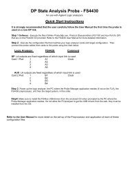
Figure 1: The FS4300 Fibre Channel Analysis ProbeMinimum EquipmentRequiredThe minimum equipment required for analysis of a FibreChannel link is:• One of the following logic analyzers: 167X, 16550A,16554A, 16555A, 16556A, 16557A, 16600, 16601,16602, 16603, 16710, 16711, 16712, 16715, 16716,16717.• The Fibre Channel Analysis Probe Product and powersupply unit.• At least one GBIC.• Appropriate physical interconnection (fibre or copper).• A Fibre Channel node.Theory of OperationThe Analysis Probe’s hardware consists of two essentiallyidentical sections. Each section can be divided into two majorfunctional blocks. One block deals with connection to a FibreChannel link and the other block deals with processing of the linkdata stream and presentation of that data to the logic analyzer.The presence of two sections allows analysis of two differentlinks. Generally, these will be the links on either side of a nodethat’s being analyzed. A multiplexer between the two sectionsallows hub-like behavior. In one configuration, the two sectionsare interconnected such that receive data comes in from one link(Channel 1) and exits on the other link (Channel 2.) Likewise,receive data from Channel 2 is transmitted on Channel 1. Bothsections provide for clock re-timing before the data is retransmitted.9
The two links can also be run independently. In thisconfiguration, receive data from Channel 1 is re-transmitted onthe transmit side of Channel 1. Channel 2 runs independently ina similar fashion. This configuration is useful for connection to ahub.Each channel of the Analysis Probe is connected to the FibreChannel via one of 2 connection points, a GBIC (GigaBitInterface Converter), or 50-Ohm SMA connectors. This allowsflexibility in the type of physical media used with the AnalysisProbe. For each channel the data received into the AnalysisProbe is processed to extract the clock, to convert the data froma serial bit stream to parallel data and to decode from the 8b/10bformat. The data is then passed to the logic analyzer as 32 bitdata words. With each data word the Analysis Probe alsogenerates another 32 bits of information that providesinformation about the data word, for example the type of frame,the type of the current word (e.g. header, CRC, payload), anyerrors detected etc. The two data words are interpreted by theFS4300 software and used to generate the listing display on thelogic analyzer.In addition to converting and decoding the data the AnalysisProbe hardware also provides support for filtering the incomingdata to assist in capturing data of interest. This is achieved bygenerating multiple clocks for clocking data to the logic analyzer.By selecting which clocks are used data such as duplicateprimitives and data payload may be filtered from the datastream. See the section “Duplicate primitive and data filtering” onpage 35 for more information on this topic.The FS4300 software configures the logic analyzer for use withthe Analysis Probe and interprets the data passed to the logicanalyzer. The configuration includes the definition of a number ofterms and symbols to assist in triggering and qualifying data tobe stored. The sections “The Format Menu” on page 5 and“Using Symbols to Trigger in State Mode.” on page 33 providemore information on these and how they may be used to assistin the analysis of a Fibre Channel interconnect.LED IndicatorsIDLE LEDPRIM LEDSOF LEDRX OK LEDThe FS4300 has 16 LED activity indicators, 8 for each section(channel). These provide a means of confirming link activity at aglance.The LED marked IDLE indicates the presence of an IDLEsymbol on the link. This LED is only valid when the relatedchannel on the FS4300 is connected to a Fibre Channel link.The LED marked PRIM indicates the presence of any primitiveword. This LED is only valid when the related channel on theFS4300 is connected to a Fibre Channel link.The SOF LED indicates the presence of Start of Frame symbols.This LED is only valid when the related channel on the FS4300is connected to a Fibre Channel link.The RX OK LED indicates that the associated GBIC is receivingdata.10
TX OK LEDComma Detect LEDSIG OK LEDRETIME OK LEDThe interface to theLogic AnalyzerThe TX OK LED indicates that the associated GBIC has beenenabled for data transmission. Note that once a TX switch hasbeen set to the enabled position the corresponding TX OK LEDwill stay illuminated until power is removed from the FS4300.The COMMA DETECT indicator is illuminated when a “Comma”character is detected indicating the start of a bit stream.The SIG OK LED indicates that the associated GBIC is correctlyinserted.If the FS4300 detects either an 8b/10b code error or a missingK28.5 character in the retimed data stream this LED will beextinguished. Otherwise this LED will be illuminated. If dataretiming is not enabled the LED will be illuminated even if anerror occurs in the data stream.The input to the logic analyzer consists of 3 parts.1. The RC terminators (90 ohm/10pf)2. The 40 pin headers3. The 40 pin cablesSetting up the16600/16700 AnalyzerThe 16600/16700 requires a special install procedure to installthe FS4300 software. To accomplish this, insert the diskettelabeled 16600/16700 Analysis Probe Software for the FS4300into the 16600/700 diskette drive. From the SYSTEMADMINISTRATION TOOLS select INSTALL under SOFTWARE.From the SOFTWARE INSTALL screen select the FLEXIBLEDISK and APPLY. The package FS4300 will now appear.Select it and then select INSTALL. This procedure does notneed to be repeated. It only needs to be done the first timethe Fibre Channel Analysis Probe is used.When this has completed restart the logic analysis session andeither invoke the Setup Assistant from the logic analyzer screenor load the appropriate configuration file from theconfigs/<strong>FuturePlus</strong>/FS4300 directory. The Setup Assistant willguide you in configuring the logic analyzer. Select <strong>FuturePlus</strong>from the list on the left of the Setup Assistant screen and thenFibre Channel from the list that then appears. If you prefer toload the configuration file yourself please refer to the section“Logic Analyzer Configuration Files“ on page 17 of this manualfor a list of analyzers and corresponding configuration files.NB: The Logic Analysis System’s Operating System must beversion A.01.40.00 with patches 034 & 035 or higher to becompatible with the software provided on the installationdiskette.Setting up Analyzersinstalled in the 16500mainframe and theportablesThe logic analyzer can be configured for Fibre Channel analysisby loading the appropriate Fibre Channel configuration file.Loading this file will load the Fibre Channel Serial bus inverseassembler and configure your logic analyzer. To load theconfiguration and inverse assembler:11
1. Install the FS4300 16500 Fibre Channel Analysis Probesoftware flexible diskette in the disk drive of the logicanalyzer.2. Configure the menu to “Load” the analyzer with theappropriate configuration file (see table below).3. Execute the load operation to load the file into the logicanalyzer that the Fibre Channel Analysis Probe moduleis connected to. DO NOT SELECT ALL OR SYSTEM.16500 Configuration FilesLogicAnalyzerNumber of PODSrequired/Numberof Cards requiredFile name forState AnalysisComment16550A 4/1 CFC43_1 One channel analysis only.Connect Logic Analyzer PODS 1-4 to FibreChannel Analysis Probe PODS 1-4 on thechannel being used.16550A 8/2 CFC43_1 Two channel analysis.The two analyzer cards must be configuredas separate logic analyzers (i.e. not asmaster/expansion). One logic analyzer isused for each channel.Connect one Logic Analyzer’s PODS 1-4 toFibre Channel Analysis Probe Channel 1PODS 1-4. Connect the other LogicAnalyzer’s PODS 1-4 to the Fibre ChannelAnalysis Probe Channel 2 PODS 1-4.Load the configuration file into each logicanalyzer.1655x 4/1 CFC43_2 One channel analysis only.Connect Logic Analyzer PODS 1-4 to FibreChannel Analysis Probe PODS 1-4 on thechannel being used.1655x 8/2 CFC43_2 Two channel analysis.The two analyzer cards must be configuredas separate logic analyzers (i.e. not asmaster/expansion). One logic analyzer isused for each channel.Connect one Logic Analyzer’s PODS 1-4 toFibre Channel Analysis Probe Channel 1PODS 1-4. Connect the other LogicAnalyzer’s PODS 1-4 to the Fibre ChannelAnalysis Probe Channel 2 PODS 1-4.Load the configuration file into each logicanalyzer.12
LogicAnalyzerNumber of PODSrequired/Numberof Cards requiredFile name forState AnalysisComment167x 4/NA CFC43_3 One channel analysis onlyConnect Logic Analyzer PODS 1-4 to FibreChannel Analysis Probe PODS 1-4 on thechannel being used.Note: The 167x can only be used for One Channel AnalysisOnly.Setting up the16505A PrototypeAnalyzerTo load the configuration and inverse assembler:1. Install the 16500 FS4300 software flexible diskette in thedisk drive of the 16500 mainframe.2. Configure the main file menu on the 16505A to “Load16500 file” with the appropriate configuration file (seetable above).The state listing screen on the 16505A should now show theFibre Channel Analysis Probe Inverse Assembly display. If itdoes not, select the base of the label DATA. This will thenshow the choice for INVASM. Select INVASM and this willinvoke the Fibre Channel Analysis Probe Inverse Assembler.Powering theAnalysis ProbeThe power supply unit supplied with the FS4200 provides therequired power for the active circuitry on the Fibre ChannelAnalysis Probe.Connecting to theAnalysis ProbeThe following explains how to connect the logic analyzer to theFibre Channel State Analysis Probe:1. Remove the probe tip assemblies from the logicanalyzer cables.2. Plug the logic analyzer cables into the Fibre ChannelAnalysis Probe cable headers as shown in theappropriate table below.Please note that with the FS4300 orientated so that the 40 pincable headers are on your right the pods number Channel 2Pod 1 - 4 and then Channel 1 Pods 1 - 4 starting with the topcable header (the one furthest away from you).13
Channel 2Pod 1Channel 2Pod 2Channel 2Pod 3Channel 2Pod 4Channel 1Pod 1Channel 1Pod 2Channel 1Pod 3Channel 1Pod 4One Channel OnlyLogic AnalyzerFibre ChannelAnalysis ProbeCommentMaster POD 1 POD 1POD 2 POD 2POD 3 POD 3POD 4 POD 4Two Channels using Twoseparate Logic AnalyzerCardsLogic AnalyzerFibre ChannelAnalysis ProbeCommentCard 1 POD 1 Channel 1 POD 1 1 st Logic Analyzer cardCard 1 POD 2 Channel 1 POD 2 1 st Logic Analyzer cardCard 1 POD 3 Channel 1 POD 3 1 st Logic Analyzer cardCard 1 POD 4 Channel 1 POD 4 1 st Logic Analyzer cardCard 2 POD 1 Channel 2 POD 1 2 nd Logic Analyzer cardCard 2 POD 2 Channel 2 POD 1 2 nd Logic Analyzer cardCard 2 POD 3 Channel 2 POD 1 2 nd Logic Analyzer cardCard 2 POD 4 Channel 2 POD 1 2 nd Logic Analyzer card14
Installing theAnalysis ProbeThe Fibre Channel Analysis Probe can be installed between twoFibre Channel nodes to monitor the traffic between them. Thefollowing steps explain how to install the State Analysis Probe.1. Install the logic analyzer cables as described in theprevious section.2. Connect the power supply plug to the power socket onthe side of the Fibre Channel Analysis probe.3. Connect the power supply to a wall socket using thepower cord.4. Attach the Fibre Channel Analysis probe to the FibreChannel network using one of the connection options(see below)5. Set the Fibre Channel Analysis probe configurationswitches to select the connection point and feed-throughor loop-back operation. (see page 22, section “SettingConfiguration Switches “)There are two ways to connect the Analysis Probe to a FibreChannel link.• The Analysis Probe can use the GBICs exclusively andtransmit real data between two full-speed Fibre Channeldevices. The data can be retimed on either channel beforeleaving the Analysis Probe (see the section “Data Re-Timing“ on page 23)• Equipment fitted with 50 ohm SMA connectors (for examplea BER tester) can be attached via four SMA connectors perchannel (2 connectors for the differential input, 2 fordifferential output)The GBIC and SMA ports are connected such that data comingin on the Channel 1 GBIC will also appear on the Channel 1SMA. This feature allows the user to “snoop” in on the data withinstruments other than the Logic Analysis System.Switches allow the selection of the major configuration options,which are:• GBIC in – GBIC out• SMA in – SMA out• Channel 1 retiming• Channel 2 retiming• Feed-through (from one channel to the other)15
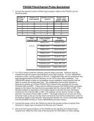
• Loop-back (data received on an input port for one channel is“looped back” and transmitted on the output port for thesame channel).Any combination of these options can be used to analyze normaldata with the Logic Analysis System, “snoop” on the data withother tools, or to implement some error injection tests. For moreinformation on selecting a configuration option see the sectionSetting Configuration Switches on page 22.Not implemented on FS430050ohm75ohmRECEIVERswitchswitchClockRegeneratorGBICswitchGBICClockRegeneratorswitchswitchRECEIVER75ohmNot implemented on FS430050ohmThe figures below show two possible ways of using the FS4300,the first to monitor traffic into and out of a Fibre Channel node,the second to monitor traffic on two independent ports.Fibre Channel NodeRTFS4300 configuredfor Feed ThroughRRTChannel 2FS4300Channel 1TRTFibre Channel NodeFigure 2: Monitoring traffic through a node.16
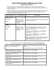
Fibre Channel NodeFibre Channel NodeRTRTFS4300 configuredfor loop back.RRTChannel 2FS4300Channel 1TRTRTFibre Channel NodeFibre Channel NodeFigure 3: Monitoring independent linksSMA Signal LevelsLogic AnalyzerConfiguration FilesOne pair of SMA connectors provides a means to monitor thereceived data as a differential voltage signal. The other pair ofconnectors may be used to source a differential signal that willbe transmitted by the associated GBIC. Signals received on theSMA connectors have a peak to peak differential voltage ofbetween 1.0V and 2.6V. Signals sourced to the FS4300 via theSMA connectors should have a differential peak to peak voltageof between 300mV and 2.6V.Users of the 16600/16700 Logic Analysis <strong>Systems</strong> may use theSetup Assistant to load the correct configuration file for the logicanalyzer configuration installed in the system.16700 Configuration FilesLogicAnalyzerNumber of PODSrequired/Numberof Cards requiredFile name forState AnalysisComment16550A 4/1 CFC43_1 One channel analysis only.Connect Logic Analyzer PODS 1-4 to FibreChannel Analysis Probe PODS 1-4 on thechannel being used.17
LogicAnalyzerNumber of PODSrequired/Numberof Cards requiredFile name forState AnalysisComment16550A 8/2 CFC43_1 Two channel analysis.The two analyzer cards must be configuredas separate logic analyzers (i.e. not asmaster/expansion). One logic analyzer isused for each channel.Connect one Logic Analyzer’s PODS 1-4 toFibre Channel Analysis Probe Channel 1PODS 1-4. Connect the other LogicAnalyzer’s PODS 1-4 to the Fibre ChannelAnalysis Probe Channel 2 PODS 1-4.Load the configuration file into each logicanalyzer.1655x 4/1 CFC43_2 One channel analysis only.Connect Logic Analyzer PODS 1-4 to FibreChannel Analysis Probe PODS 1-4 on thechannel being used.1655x 8/2 CFC43_2 Two channel analysis.The two analyzer cards must be configuredas separate logic analyzers (i.e. not asmaster/expansion). One logic analyzer isused for each channel.Connect one Logic Analyzer’s PODS 1-4 toFibre Channel Analysis Probe Channel 1PODS 1-4. Connect the other LogicAnalyzer’s PODS 1-4 to the Fibre ChannelAnalysis Probe Channel 2 PODS 1-4.Load the configuration file into each logicanalyzer.167xx 4/1 CFC43_3 One channel analysis only.Connect Logic Analyzer PODS 1-4 to FibreChannel Analysis Probe PODS 1-4 on thechannel being used.167xx 8/2 CFC43_3 Two channel analysis.The two analyzer cards must be configuredas separate logic analyzers (i.e. not asmaster/expansion). One logic analyzer isused for each channel.Connect one Logic Analyzer’s PODS 1-4 toFibre Channel Analysis Probe Channel 1PODS 1-4. Connect the other LogicAnalyzer’s PODS 1-4 to the Fibre ChannelAnalysis Probe Channel 2 PODS 1-4.Load the configuration file into each logicanalyzer.18
The Inverse AssemblerThe Fibre Channel Inverse Assembler is auto loaded into thelogic analyzer when the configuration file is loaded.• IFS4300 is the Inverse Assembler for all supported logicanalyzers installed into the 16500A/B/C mainframe. If theInverse Assembler does not appear on the state listingscreen select the base of the label DATA. From the menuthat appears select INVASM• IFS4300E is the Inverse Assembler for all logic analyzersinstalled into the 16600 and 16700.The Format MenuThe STAT variableThe ADDR and DATAvariablesOther Labels andSymbols.The Fibre Channel Analysis Probe diskette sets up the formatmenu to include all of the signals that are presented to the logicanalyzer. The labels STAT, DATA, ADDR are required in orderrun the Inverse Assembler. They should not be changed ordeleted from the format menu. Appendix A documents therequired format definitions for use with the FS4300.The STAT variable is used by the Fibre Channel inverseassembler to decode Fibre Channel transactions. It should notbe changed or deleted from the format menu. The fields thatmake up the STAT variable are listed in the following table.The ADDR and DATA variables are defined in the format menu.The DATA variable is used to pass the Fibre Channel datawords to the Inverse Assembler during state analysis. TheADDR variable is not used but must be defined for the InverseAssembler to function correctly. These variables should not bechanged or deleted from the format Menu.The following table describes the other labels that are defined foruse with the Analysis Probe.FieldCountFrmTypWrdTypSOFTypDescriptionA 9 bit field that counts from 0 up through the end of each ‘section’ of a frame. Theheader, optional header, and payload sections are all covered. This field provides theability to qualify storage or trigger specifications on one or more specific words in theframe. This counter is also used to provide information about suppressed primitivesduring the inter-frame time. Count is only valid for this purpose during states whenWrdTyp has the value of Header, OptHeader or Payload. Count is also used to indicatethe number of suppressed primitives (see page 35 )A 10 bit field that represents unique values for many of the popular FC-1 and FC-4frames. Examples include FCP_CMND frames and PLOGI and ACC frames. This fieldalleviates the need for complicated trigger sequences that look, sequentially, at theR_CTL, TYPE, and payload word 0 fields. It is valid for the entire frame (SOF to EOF)and therefore can be used to qualify other fields within a frame. This field is undefinedduring the inter-frame time and is normally output as zeroes.A 4 bit field that describes the type of each word in the link data stream. Inter-frameprimitives are distinguished from frame header, payload, and CRC words. In addition, linkerrors are flagged in this field.A 3 bit field that encodes the type and class of service for SOF primitives. It Is valid duringthe states when WrdTyp is SOF/Node_IDs.19
FieldEOFtypS_IDD_IDPrimtvAL_PAs20sDescriptionA 3 bit field that encodes the type and class of service for EOF primitives. It Is valid duringthe states when WrdTyp is EOF.A 24 bit field that holds the S_ID field from the frame header. This field is only definedduring the states when WrdTyp is SOF/Node_IDs.A 24 bit field that holds the D_ID field from the frame header. This field is only definedduring the states when WrdTyp is SOF/Node_IDs.This field is valid when WrdTyp is Primitive, it indicates the type of primitive on the link.16 bit field that holds 2 Arbitrated loop Physical Address fields. This field can be used toidentify primitives such as ARB that contain specific AL_PAs. It is only valid during thestates when WrdTyp is Primitive.A single bit field that is normally zero. Approximately every 20 seconds, this field is a onefor a single cycle of the unique (J) clock. It is useful for preserving time correlation bypreventing ambiguity in the logic analyzers time information (see page 38 for more detail).These labels are provided to simplify the specification of triggerevents and storage qualifiers. Note that some of the fields in alabel “overlap” each other (that is, share bits of a pod). This isbecause the information passed from the Bus Analysis probe tothe logic analyzer is context (state) dependent. In general thevalue of the WrdTyp (Word Type) label in a particular statedetermines which other labels are valid in that state. Forinstance, during a state that represents a SOF (characterized bya WrdTyp of SOF/Node_IDs,) the S_ID and D_ID fields areactive and the fields they overlap, DATA and Count are not.During a state when WrdTyp is Primitive, however, the S_ID andD_ID fields are not active and the DATA and Count fields are.As a consequence some care must be taken when specifyingtrigger conditions to ensure that terms are qualified with otherlabels so that they are only valid in the correct state. Forexample, consider specifying a term, in the trigger menu, totrigger on a frame with a particular source and destination ID.As described above the S_ID and D_ID fields are only valid witha WrdTyp of SOF/Node_IDs. Therefore the trigger term has tobe specified with both a WrdTyp of SOF/Node_IDs and thevalues for the source and destination nodes in the S_ID andD_ID fields respectively.Note also that as the D_ID field overlaps the Count field, placinga value in the D_ID field specified will also cause a value toshow in the Count field.The table below summarizes the validity of the format labelsduring the various WrdTyp states.For a full list of available labels and related symbols either lookunder the FORMAT section of the logic analyzer once theFS4300 software is loaded or see Appendix A.20
Word TypeNode_IDs(SOF)SyncingLinkOpenErrorFormat LabelDATA Count FrmTyp WrdTyp SOFTyp EOFTyp S_ID D_ID Primtv AL_PAs• • • (1) • •••Primitive • • •(2)Header • • • •OptHeader • • • •Payload • • • •CRC (good) • •CRC(bad) • •EOF • • • (3)CodeViolationPrimitiveErrorFramingError•••Notes:(1) The SOFType field overlaps the WrdTyp Field so that specifying the SOFTyp using a symbol alsospecifies the WrdTyp as Node_IDs (SOF).(2) Some Primitives such as ARB contain one or more AL_PAs. When these are to be specified the AL_PAfield can be used for that purpose.(3) The EOFType field overlaps the WrdTyp field so that specifying the EOFTyp using a symbol alsospecifies the WrdTyp as EOF.21
State AnalysisThis chapter explains how to configure the Fibre ChannelAnalysis Probe to perform state analysis. The configurationsoftware on the flexible diskette sets up the format specificationmenu of the logic analyzer.Installation QuickReferenceThe following procedure describes the major steps required toperform measurements with the Fibre Channel Analysis Probe.1. After removing the probe tip assemblies, plug the logicanalyzer cables into the Analysis Probe cable headers.See page 13 of this manual for details.2. Insert one or two GBICs into the GBIC slots on the sidesof the unit.3. Plug the power supply connector into the power jack onthe side of the FS4300 and then connect the powersupply to a wall socket using the power cord provided.4. Attach the Fibre Channel Analysis Probe to the FibreChannel links.5. Configure the FS4300 by setting the switchesappropriately.Load the logic analyzer configuration file by loading theappropriate file from the appropriate FS4300 software diskette.See page 17 of this manual for details.Setting ConfigurationSwitchesThe connection to the Analysis Probe can be configured using anumber of switches. The switch function is indicated on the unitand described in the following sections.Disabling the GBICTransmitterFor each channel there is a switch to disable the GBICtransmitter. Setting the switch labeled GBICn TX to the disableposition will disable the GBIC for channel n (where n is either 1or 2). To enable the GBIC transmitter for a channel set theappropriate switch to the enable position.Selecting Fibre ChannelSourceFor each channel the Fibre Channel data may be sourced fromeither the GBICs or the SMA connectors. Two switches (perchannel) are used to select the source of data to the LogicAnalyzer from the GBIC to the SMAs. The markings on theFS4300, near the SMA connectors indicate the data paththrough the two switches. For example, with the FS4300orientated so that the GBICs are on the left and the two source22
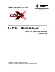
selection switches both set to the down position the Channel 1data to the analyzer will come from the Channel 1 GBIC. If theleft most switch is now moved to the up position then Channel 1data will be sourced from the Channel 1 SMAs. The other sourceselection switch should be permanently left in the down position(for Channel1, up for Channel 2).Enables DataRetiming forChannel 1Selects GBIC orSMA. This positionselects GBIC forChannel 1..This switch must bedown. (Channel 2switch must be up)Selecting Feed-Throughor Loop-BackData Re-TimingThe switch in the center of the unit allows the Analysis Probe tobe configured as either a feed-through device or a loop-backdevice. With the switch in the right position (marked FEEDTHROUGH), data entering Channel 1 GBIC will exit Channel 2GBIC and vice versa. With the switch in the left position (markedLOOP BACK), data entering Channel 1 GBIC will “loop back”and exit the Channel 1 GBIC. Similarly data entering theChannel 2 GBIC will “loop back” and exit the Channel 2 GBIC.To reduce jitter the Analysis Probe has the capability to retimethe data on each channel before sending it out on the otherchannel. The switches at the top and bottom of the unit, above(Channel 2) and below (Channel 1) the LED’s marked RETIMEOK enable the retiming of the data before it leaves the AnalysisProbe (see figure above).Enabling ClockSuppressionThe switches marked CLK SUPP enable filtering using clocksuppression for each channel (see section 2.1). With the switchset to the OFF position the FS4300 generates a clock to thelogic analyzer for all events on the associated channel. As aconsequence all events will be passed to the logic analyzer’smemory and filtering of duplicate primitives or data payload byselecting the logic analyzer’s clocks will not be possible. Settingthis switch to the ON position causes the FS4300 to generateseparate clocks for some events and therefore allows filtering ofdata prior to storage in the logic analyzer’s memory.23
Mode SwitchThere is also a “mode” switch on the bottom right hand side ofthe unit. This switch is not used on the FS4300.Acquiring DataThe State ListingDisplayTouch or click RUN on the logic analyzer and as soon as there isactivity on the bus the logic analyzer will begin to acquire data.The analyzer will continue to acquire data and will display thedata when the analyzer memory is full, the trigger specification isTRUE or when you touch or click STOP.The logic analyzer will flash “Slow or Missing Clock” if there is noactivity on the fibre links or if the activity has been filtered by useof the logic analyzer’s clock configuration.Data from the logic analyzers connected to the two channels onthe FS4300 may either be displayed in separate listing windowsor in a single listing window. Using a single listing window allowsboth channels to be easily viewed simultaneously. To maintaincorrect timing relationships it is necessary to set up anappropriate trigger arming control and timing correlation. Pleaseconsult your Logic Analysis System’s documentation on how todo this. Figure 4 below shows an example of state displaysfrom both channels in a single listing window.Figure 4: Two channels displayed in one listing windowPresentation ofInformationThe inverse assembler is designed to produce listings on a16500 screen that accommodate viewing the activity on two linksat the same time. As a result, the output text is limited to 30columns and the density of information on the screen can behigh. To assist the visual location of various sections of a frame,special characters in the first column delimit each section. Figure13 on page 36 shows an example of this. Note that inter-frameprimitives are indented from the frame data. Also note that theSOF and EOF ordered set delimiters are not indented at all. Allother frame data is preceded with a special character. The24
header is preceded by a ‘|’, the payload is preceded by a blank,and the CRC word is preceded by a ‘*’. On the 16700 LogicAnalysis System the various parts of a frame are also identifiedwith different color. These features, combined with the displaymode options make it easier to scan the trace listings and findactivity of interest.Inverse AssemblerModes of OperationSelecting Display Modeon the 16500A/B/CThe FS4300 inverse assembler provides 3 display modes. Themethod used to select the display modes depends upon the typeof Logic Analysis system used.For the 16500A/B/C family of Logic Analysis <strong>Systems</strong> the modeis selected from the Invasm pulldown menu on the listingscreen. The items in the menu are not configurable by theinverse assembler. As a consequence, you must remembermenu item positions rather than descriptive labels to make yourchoices. Of the 8 choices, only the first 3 are useful.The following table summarizes the modes of operationavailable:Menu ChoiceMode of OperationSize 16 Byte 0Size 16 Byte 1Size 16 Byte 2Full mode. All analyzer states decoded. (Default mode)Summary mode. Only SOF states are decoded. Each frame issummarized on the SOF line.Configuration mode. Analysis Probe configuration and stateinformation is presented on some of the analyzer states thatcontain a primitive. Only this configuration and state data ispresented. None of the link data is decoded.Selecting Display Modeon the 16700For the 16700 Logic Analysis System the inverse assembler’sdisplay mode is selected from the Preferences menu under theInvasm pulldown menu on the listing screen. Selecting DisplayOptions will display a selection screen. By default the mode isFull, other display options can be selected by clicking on thebutton in the Display Options selection screen.25
Full ModeFigure 5: Selecting the Display OptionIn this mode, the inverse assembler decodes as much of eachstate as possible. When the complete link data stream is notpresent in the trace memory, some parts of the frame cannot becompletely decoded. Figure 6, below, shows the FS4300 InverseAssembler in Full mode.For most fields in a frame Full mode decodes the field into easilyunderstood symbols. However for some fields it is necessary tosignificantly abbreviate the information in order to optimize thedisplay. In particular the Frame Control field is displayed as astring of characters representing the various bit fields within theFrame Control field. The table below shows how the value ofeach bit field is represented in the Full mode display.Frame ControlFieldUse Values Displayed23 Exchange Context Exchange OriginatorExchange Responder22 Sequence Context Sequence InitiatorSequence Responder21 First Sequence Not First Sequence of ExchangeFirst Sequence of Exchange20 Last Sequence Not Last Sequence of ExchangeLast Sequence of Exchange19 End Sequence Not Last Frame of SequenceLast Frame of Sequence18 End Connection Connection ActiveEnd of Connection PendingORIR.F.L.L.E26
Frame ControlFieldUse Values Displayed17 Chained Sequence No Chained Sequence (Class 1)Chained Sequence Active (Class 1)16 Sequence Initiative Hold Sequence InitiativeTransfer Sequence Initiative15 X_ID reassigned X_ID assignment retainedX_ID assignment re-assigned14 Invalidate X_ID X_ID assignment retainedInvalid X_ID13:12 ACK Form No assistance providedACK1 RequiredACK_N RequiredACK _0 Required11 Data Compression UncompressedCompressed10 Data Encryption UnencryptedEncrypted9 Retransmission Original SequenceRetransmitted Sequence8 Unidirectional Transmission Bi-directional Class 1 ConnectionUnidirectional Class 1 ConnectionOther i.e. not Class 1 Connection)7:6 Continue Sequence No Information on next SequenceSequence to follow immediatelySequence to follow soonSequence to follow delayed5:4 Abort Sequence Condition Value depends upon whether the frame isan ACK or the first data frame of anExchange from the Exchange Originator.Therefore just the binary value for the twobits is displayed.3 Relative Offset Present Parameter field not meaningfulParameter field gives relative offset2 Reserved Reserved for Exchange reassembly. Thevalue of bit 2 is displayed1:0 Fill Bytes 0 Bytes of fill1 Byte of fill2 Bytes of fill3 Bytes of fill01HX.R.I---1-N-0UCUE.RBU.---I-S-D00011011.R01-0-1-2-3The Frame Control field is displayed on the same line as theType field so the example in Figure 6 shows a frame with TypeFCP and a Frame Control field of:27
OIF.L.0X..--UU..--00.0-0From the table this can be interpreted as:OIFExchange OriginatorSequence InitiatorFirst Sequence of Exchange. Not the last Sequence of ExchangeLLast Frame of Sequence. Connection Active0 No Chained SequenceXTransfer Sequence Initiative. X_ID assignment retained. X_ID assignment retained (i.e. valid)-- ACK form of “no assistance provided”UUUncompressed dataUnencrypted data. Original Sequence. Uni/bidirect transmission field not valid for this class-- No information on next sequence00 Abort Sequence Condition = 00. No Relative Offset0 Exchange reassembly bit = 0-0 0 bytes of fill28
Figure 6: Full Display ModeSummary ModeThe second mode of operation is the Summary mode (seeFigure 7 below). This mode reduces the amount of datapresented to make it easier to scan a listing to find a particularframe. The main characteristics of the frame are summarized onthe SOF line. The rest of the states within the frame are leftundecoded (blank). This usually provides a listing with a lot ofwhite space and isolated lines that describe the frame type, nodeIDs, and X_ID. Operation in Summary mode facilitates rapidscanning of traces to find a particular frame. Once the frame islocated the display mode can be changed to Full to see theframe details.To conserve space on the output line the frame information isabbreviated to the form:S_ID > D_ID X_ID Frame TypeThe X_ID is abbreviated further by removing any leading zerosin the OX_ID and RX_ID fields and replacing a field ofFFFF(hex) with the character *. For example an X_ID of29
00010222 will be displayed as 1222 and X_ID of 0111FFFF willbe displayed as 111*. In some cases this will mean that theboundary between the OX_ID and the RX_ID is not discernible.However the X_ID field will still be a unique identifier that can beused to help identify an exchange. Changing the display mode toFull will show the full OX_ID and RX_ID.The Summary mode of operation may be used in conjunctionwith a filter on the 16700 Logic Analysis System. Data from theanalyzer can be piped to a filter and then to a listing window. Ifthis filter is configured to only pass SOF states, the resultantdisplay will show only the SOF states in the capture memory.However, all of the states are still available to the inverseassembler. Therefore, if the inverse assembler is put inSummary mode, and all of the states for the frame are incapture memory, the frame summary will be available. Theresultant display will be a dense listing, with a one line summaryof a frame on each line. Figure 8 shows how to pipe the logicanalyzer output to a filter. Figure 7 shows how to specify a filterfor this purpose. Figure 10 shows the result of filtering the dataand displaying the results using the Summary display mode.Figure 7: Summary Display Mode30
Figure 8: Setting up a data filter for use with SummaryDisplay ModeFigure 9: Filter specification for use with Summary DisplayMode31
Configuration ModeFigure 10: Result of Filter combined with Summary DisplayModeIn this mode of operation, the inverse assembler displaysinformation about how the FS4300 Analysis Probe is configured.Figure 11 shows an example of a Configuration mode display.The configuration data is only available on states representingFibre Channel primitive words (e.g. IDLE). If there are none ofthese states in the analyzer’s memory, no configurationinformation will be displayed.32
Figure 11: Configuration Display ModeUsing Symbols toTrigger in StateMode.The labels and symbols provided may be used to trigger on thevarious fields of a frame. There are two types of labels. One typeof label is used to define values for fields within the frame (e.g.source and destination Ids). The other type is used to qualifythose fields within the data passed to the analyzer.The following sections give some examples of how to use theselabels.Triggering on a FrameType & fields within aframe.The FrmTyp label may be used to define a trigger termspecifying the required type of Frame. Symbols are defined for anumber of different frame types. The FrmTyp label is validthroughout a frame so may be used to qualify triggering on otherfields within a particular frame type. For example setting up atrigger term that defines the conditions FrmTyp = FCP_CMD,WrdTyp = Payload, Count = 003 and Data = 12xxxxxx (hex) willcreate a trigger for a SCSI Inquiry command. In this example thevalue of FrmTyp specifies a FCP command, the WrdTypspecifies a state representing payload and the combination ofCount and DATA specify that the 3 rd payload word must be12xxxxxx (hex). The most significant byte of the 3 rd word of anFCP command frame payload holds the CDB opcode (in thiscase Inquiry) so the combination of labels specifies the SCSIInquiry command33
Triggering on aDestination ID or SourceIDThe D_ID label may be used to define a destination node id tobe matched in a trigger condition. However, the fields of thislabel are only valid as a destination node id during states forwhich WrdTyp has the value SOF/node_ids . Therefore it isnecessary to add a qualifier of WrdTyp = SOF/node_id for theD_ID label in the trigger term. Together they may be used todefine a trigger condition specifying a particular destinationnode. Define a trigger term specifying WrdTyp and D_ ID. In thevalue field for the D_ID label define the required destinationnode ID, set the WrdTyp value to be symbol and select thevalue SOF/node_id.A trigger for a source node id can be defined using the labelS_ID again suitably qualified with WrdTyp. Similarly, to triggeron a packet from a specific source node to a specific destinationnode set up a trigger term that uses both S_ID and D_ID bothqualified with WrdTyp having a value of SOF/node_ids<strong>Manual</strong> TriggerNormally, if the trigger condition is met, the Logic AnalysisSystem can correctly correlate the data captured in its tracememory from two logic analyzer cards. However, if the triggercondition is never satisfied, and the STOP button is used to stop(and therefore “trigger” the end of data capture in the tracememory) the trace (i.e. the data from the two cards) is usuallynot time correlated. This makes it difficult to implement a “triggeron no state” trace where you want to capture the last n states onboth parts of a link that has gone down but not come back up.To help with this problem the Fibre Channel Analysis Probeprovides a manual trigger for each channel. When the trigger isactivated the next state’s WrdTyp is replaced with a value of<strong>Manual</strong>Trigger which can be included in a trigger specification totrigger the logic analyzer(s).The manual trigger for each channel may either be activated bya switch or by an external signal. The switches are located nearthe connectors for the Logic Analyzer. An external trigger signalcan be connected to the 3 pin connector near the edge of theAnalysis Probe. The ground and trigger pins can be attached tothe outputs of the Target Control module of a Logic AnalysisSystem. Use of the Target Control feature of the Logic AnalysisSystem allows the application of a manual trigger withoutphysically being near the Analysis Probe (to depress theswitch.) Therefore, one could cause a manual trigger whileoperating the Logic Analysis System from a remote site via anetwork connection. A low going pulse of any duration activatesthe external manual trigger pin. Therefore the Target Controlmode for the signal being used should be pulse mode and theinactive state should be 1 with an active state of 0Qualifying Storage ofPacketsThe labels and symbols provided may also be used to qualify thestorage of data acquired from the Fibre Channel. For examplethe Frame Type (FrmTyp) label, which is valid throughout aframe, may be used to qualify other fields within the frame andcause the analyzer to only capture frames of a particular type.Storage qualifiers may be defined in the same way as triggerterms (see page 33, “Using Symbols to Trigger in State Mode.”)34
Duplicate primitiveand data filteringOften the depth of logic analyzer’s trace memory is insufficient tocapture all data over the time of interest. In these cases, it isnecessary to reduce the data that’s captured so that fewerqualified states are captured per unit of time. It is possible to dothis using additional analyzer resource terms to qualify the datato be captured. However, this can consume many of theresource terms and significantly reduce the number left tospecify the desired trigger condition. The Analysis Probe isdesigned to help in this area by providing a flexible method offiltering data before it’s presented to the analyzer. This feature isimplemented in two general areas: filtering of inter-frameprimitives and filtering of FCP_DATA payloads.Duplicate primitive and data filtering is implemented usingmultiple clocks. The user selects what level of filtering isperformed by enabling or disabling clocks in the FORMAT menuof the logic analyzer. When a channel is configured with clocksuppression ON a base clock (J clock) is generated thatprovides an edge for every unique word present on the link. Thisclock has missing edges for duplicate primitives and for certainFCP_DATA payload words. Other clocks (K clock and L clockrespectively) are available to clock in these suppressed words ifthey are desired. By defining the logic analyzer’s clockingscheme to be a combination of the unique clock (J) the duplicateprimitive clock (K ) and the FCP data payload clock (L) varyingdegrees of filtering may be achieved. All clocks are active on therising edge.Inter-frame PrimitiveFilteringRemoving inter-frame primitives is one of the most usefulapplications of the filtering mechanism. It’s not uncommon tohave thousands of IDLEs or ARBs present on a lightly loaded FClink. With clock suppression enabled a J clock edge will begenerated for the first occurrence of a primitive and a K clockedge for all duplicate primitives (until a different event is detectedon the channel). By configuring the logic analyzer (from theFormat menu) to clock on the J clock and not the K clock thefiltering feature allows the user to see the first occurrence of aprimitive but none of the subsequent ones. For example, Figure12 (page 36) shows a listing captured with both J and K clocksenabled so the all inter-frame primitives are captured (i.e. thelogic analyzer clock is defined as the rising edge of J or therising edge of K). Figure 13 (page 36) shows the same channelactivity captured with the K clock “Off”.35
Figure 12: Activity captured with all primitivesFigure 13: Activity captured with primitives filtered36
The FS4300 also provides a mechanism to provide informationon how many primitives are present on the link without capturingall of those states. Normally, the Count field is used to indexinto the header and payload sections of the frame. However,during the inter-frame time, this field provides information aboutprimitive suppression. For each unique primitive Count is 0. Forsuccessive primitives, the Count field increments as long as thesame primitive occurs (this can be seen in Figure 12 on page36). When a new primitive occurs, the Count field persists forone more state and count information for the prior primitive isclocked with the new, unique primitive. This is necessary so thatwhen the duplicate primitive (K) clock is not enabled, the unique(J) clock will capture information on word filtering. An example ofthis behavior can be seen in the figure below. The value ofCount associated with the R_RDY state indicates that 5 IDLEshave been filtered out prior to the R_RDY primitive occurring.Figure 14: Use of the Count label to indicate filteredprimitivesDuring the inter-frame time, the Count field counts differentlythan inside a frame. It is a 9 bit counter but during the interframetime, the MSB is used to capture overflow. Therefore, itshould be treated as an 8 bit counter with an overflow indicator.37
This allows direct measurement of up to 255 (2 8 -1) suppressedstates. If the overflow bit is set, the elapsed time can be used todetermine how many times the counter overflowed. Under thesecircumstances, the Count field is a MOD 256 of the actual countvalue.Also note that the Count field does not show the suppressioncount for the primitive that immediately precedes a SOF word.This is because the Count field is not available in a staterepresenting SOF as it is “overloaded” and used to convey partof the destination node id. Elapsed time is the only methodavailable for estimating the number of suppressed states underthese circumstances.Filtering DataPayloadThe 20s LabelError MessagesTo further assist in conserving acquisition memory it is possibleto filter data payload information from FCP data frames prior tocapture in memory. The Analysis Probe clocks the first 4 words(16 bytes) of the frame payload to the logic analyzer on theunique clock (J clock) and the rest of the payload on the FCPdata payload (L) clock. Many test programs write block-uniquedata in the first several bytes of each block and this AnalysisProbe feature gives visibility of this without requiring the captureof the entire frame payload. The default configuration disablesthe L clock so only the first 4 words of the payload will be passedto the analyzer’s memory. If it is necessary to capture the entireframe enable the L clock in the logic analyzer’s Format menu.The logic analyzer uses an internal 32 bit counter to measureelapsed time between the capture of each state. This clockserves several purposes including providing a means tocorrelate trace data from two separate analyzer cards. Theperiod of this clock is 8nS and therefore, it rolls over every 35seconds. If more than 35 seconds elapses between any twostates captured by a state analyzer, the actual elapsed timebecomes ambiguous. For example if 36 seconds elapsesbetween states, or 71 seconds elapsed between states the clockcounter will indicate 1 second has elapsed (since it rolled over.)The FS4300 deals with this problem by forcing a state to becaptured approximately every 20 seconds. There is a single bitfield in the format specification called 20s. This bit is normally a0 but every 20 seconds is asserted to a 1 for a single cycle of theunique (J) clock. Consequently the analyzer is guaranteed tocapture a state at least every 20 seconds (before the counterrolls over) and therefore prevents ambiguity in the timinginformation.The Analysis Probe is capable of detecting several kinds of linkerrors. When one of these error conditions is present, it takesprecedence over other state information and the Word Type fieldwill contain the error detail. The following table describes thepossible error states, their priorities, and their meanings. Thepriority field in the table indicates what error type the AnalysisProbe will generate when multiple error conditions exist. Forexample, a primitive occurring inside the bounds of a frame is aframing error. However, if that primitive were not valid, it wouldbe labeled with a primitive error rather than a framing error.38
Priority Error Description1 Link Error This error occurs when the link is down.2 Synchronizing Not really an error, this is a start up state. The AnalysisProbe enters this state following a reset and remains inthis state until a valid SOF word is found.3 Coding Error An invalid 10 bit transmission character wasencountered. It could not be decoded to a valid 8 bitcharacter.4 Primitive Error An ordered set beginning with K28.5 was encounteredbut the following 3 transmission characters could not bedecoded into a valid primitive.5 Framing Error An invalid primitive was encountered inside a frame.Since the Analysis Probe synchronizes on the SOFcharacter, this error should only occur after a valid SOFhas been observed.Post ProcessingFiltersPost Processing Filters are only available with the 16600 or16700 mainframe logic analyzers. These filters enhance thelisting display by either coloring various aspects of capturedactivity to assist in quickly identifying areas of interest or byremoving information from the display that is not of immediateinterest. Since the FS4300 provides a number of functions toassist pre-processing filtering of data the post-processing filtershave primarily been created to assist in displaying the data byuse of colorsTo invoke the display filters or to change the color associatedwith a frame section select FILTER from the INVASM menu inthe state listing display. The following selections can besuppressed or shown.• Frame Headers• Data Payload• Primitives (e.g. IDLE, ARBx, CLS)• Optional Headers• States which captured a primitive when the 20 second timerhas expired• State which captured information other than a primitive whenthe 20 second timer has expired• Errors• A state captured because the manual trigger was activated• Start of Frame (SOF)/End of Frame (EOF)• Other states (Miscellaneous)39
A default color scheme has been selected for each filter in thelist above. The color for a filter can be changed by selecting thebutton to the right of the filter in the list displayed on the logicanalyzer.The acquired state listing display can be modified to filter out anycombination of the above transactions or cycles by selecting theshow/suppress button to the left of the list. Note that unlike thefiltering of the data payload described in the section FilteringData Payload (page 38) post processing filters only removeinformation from the display and not from the logic analyzer‘sacquisition memory.40
General InformationCharacteristicsAnalysis Probe InterfaceCompatibilityThis chapter provides additional reference information for theFibre Channel Analysis Probe module.The following operating characteristics are not specifications, butare typical operating characteristics for the Fibre ChannelAnalysis Probe module.The Fibre Channel Analysis Probe is compatible with the GigaBit Interface Converter (GBIC) specificationPower RequirementsLogic Analyzer RequiredNumber of Probes UsedMaximum SpeedEnvironmentalTemperatureAltitudeThe FS4300 requires a 5V, 4A DC power source. A suitablepower supply unit is supplied with the FS4300. No other powersupply unit should be used.167x,16550A, 16554A, 16555A, 16556A, 16557A, 16600,16601, 16602, 16603, 16710, 16711, 16712, 16715, 16716,16717.Four cable headers per channel; 2 channels supported. Only 1channel supported on the 167x.The Fibre Channel Analysis Probe supports transfers up to1Gbit/sec (1.0625 Gbits/sec)Operating: 0 to 55 degrees C (+32 to +131 degrees F)Non operating: -40 to +75 degrees C (-40 to +167 degrees F)Operating: 4,6000m (15,000 ft)Non operating: 15,3000m (50,000 ft)HumidityTesting andTroubleshootingServicingUp to 90% non-condensing. Avoid sudden, extreme,temperature changes, which would cause condensation on theAnalysis Probe module.There are no automatic performance tests or adjustments for theFibre Channel Analysis Probe module. If a failure is suspectedin the Fibre Channel Analysis Probe module contact the factoryor your <strong>FuturePlus</strong> <strong>Systems</strong> authorized distributor.The repair strategy for the Fibre Channel Analysis Probe ismodule replacement. However, if parts of the Fibre ChannelAnalysis Probe module are damaged or lost contact the factoryfor replacement parts.41
Appendix A: Format DefinitionsThe format menu contains a number of label and symboldefinitions that are useful for setting up triggers and dataacquisition filters. These definitions are shown in the followingtables.Label Pod 4 Pod 3 Pod 2 Pod 1DATA 15:0 15:0ADDR 2:0 15:0STAT 15:0 15:0Count 8:0FrmTyp 2:0 15:9WrdTyp 9:6SOFTyp 5:3EOFTyp 5:3S_ID 7:0 15:0D_ID 15:9 8:0 15:8Primtv 7:0 15:0AL_PAs 15:020s 15Primtv SymbolIDLER_RDYOLSLRLRRARBOPNCLSMRKLIP acqDefinition95B5B5954A4A358A5549BF4935BF4994XXXX91XXXX85B5B55FXXXX15F7F742
Primtv SymbolLIP failLIPLPELPE allLBPDefinition15F8F715XXXX05XXXX05FFXX09XXXXFrmTyp SymbolDefinitionLISM 0000100001TEST 0000100000LIFA 0000100010LIPA 0000100011LIHA 0000100100LISA byp 0000100101LIRP 0000100110LILP 0000100111LISA 0000110101FCP_DATA_OUT int 0010000000FCP_DATA_OUT las 0010000001FCP_DATA_OUT 001000000XFCP_DATA_IN int 0010000010FCP_DATA_IN last 0010000011FCP_DATA_IN 001000001XFCP_DATA00100000XXFCP_XFER_RDY ori 0010000100FCP_XFER_RDY res 0010000101FCP_XFER_RDY 001000010XFCP_CMND 0010000110FCP_RSP 0010000111LS_RJT 0100000001ACC 1000000010PLOGI 1000000011FLOGI 1000000100LOGO 1000000101ABTX 1000000110RSC 100000011143
FrmTyp SymbolDefinitionRES 1000001000RSS 1000001001RSI 1000001010ESTS 1000001011ESTC 1000001100ADVC 1000001101RTV 1000001110RLS 1000001111ECHO 1000010000RRQ 1000010010PRLI 1000100000PRLO 1000100001SCN 1000100010TPLS 1000100011TPRLO 1000100100GAID 1000110000FACT 1000110001FDACT 1000110010NACT 1000110011NDACT 1000110100QoSR 1001000000RVCS 1001000001PDISC 1001010000FDISC 1001010001ADISC 1001010010RNC 1001010011NOP 1110000000ABTS 1110000001RMC 1110000010BA_ACC 1110000100BA_RJT 1110000101PRMT 1110000110ACK_1 1111000000ACK_N 1111000001P_RJT 111100001044
FrmTyp SymbolDefinitionF_RJT 1111000011P_BSY 1111000100F_BSY (DF) 1111000101F_BSY (LC) 1111000110LCR 1111000111WrdTyp SymbolDefinitionSOF (Node Ids)X000Primitive 0010Header 0100Opt Header 0110Payload 1010CRC (good) 1100EOF 1110Syncing 0001<strong>Manual</strong> Trigger 0011Code Violation 0101Primitive Error 0111Framing Error 1001CRC (bad) 1001Link Error 1101SOFTyp SymbolDefinitionSOF f 000SOF n1 001SOF n2 010Sof n3 011SOF c1 100SOF i1 101SOF i2 110SOF i3 11145
EOFTyp SymbolDefinitionEOF t 000EOF dt 001EOF dti 011EOF n 100EOF a 101EOF ni 11146